EP4258589A2 - Tci acquisition mechanism for the activation of an unknown secondary cell woriking on a fr2 band - Google Patents
Tci acquisition mechanism for the activation of an unknown secondary cell woriking on a fr2 band Download PDFInfo
- Publication number
- EP4258589A2 EP4258589A2 EP23194730.0A EP23194730A EP4258589A2 EP 4258589 A2 EP4258589 A2 EP 4258589A2 EP 23194730 A EP23194730 A EP 23194730A EP 4258589 A2 EP4258589 A2 EP 4258589A2
- Authority
- EP
- European Patent Office
- Prior art keywords
- scell
- rsrp
- information
- activation
- rsrp measurement
- Prior art date
- Legal status (The legal status is an assumption and is not a legal conclusion. Google has not performed a legal analysis and makes no representation as to the accuracy of the status listed.)
- Pending
Links
- 230000004913 activation Effects 0.000 title claims abstract description 139
- 230000007246 mechanism Effects 0.000 title description 3
- 238000005259 measurement Methods 0.000 claims abstract description 203
- 238000000034 method Methods 0.000 claims abstract description 69
- 230000005540 biological transmission Effects 0.000 claims abstract description 24
- 230000010267 cellular communication Effects 0.000 claims description 30
- 238000005516 engineering process Methods 0.000 claims description 16
- 238000001994 activation Methods 0.000 description 139
- 238000004891 communication Methods 0.000 description 79
- 238000012545 processing Methods 0.000 description 41
- 230000015654 memory Effects 0.000 description 29
- 230000008569 process Effects 0.000 description 28
- 238000010586 diagram Methods 0.000 description 27
- 230000006870 function Effects 0.000 description 16
- 230000001413 cellular effect Effects 0.000 description 6
- 230000003287 optical effect Effects 0.000 description 5
- MJSPPDCIDJQLRE-YUMQZZPRSA-N S-methionyl-L-thiocitrulline Chemical compound CSCC[C@@H](C(S/C(\N)=N/CCC[C@@H](C(O)=O)N)=O)N MJSPPDCIDJQLRE-YUMQZZPRSA-N 0.000 description 4
- 230000003213 activating effect Effects 0.000 description 4
- 230000000737 periodic effect Effects 0.000 description 4
- 238000003860 storage Methods 0.000 description 4
- 230000002776 aggregation Effects 0.000 description 2
- 238000004220 aggregation Methods 0.000 description 2
- 238000004590 computer program Methods 0.000 description 2
- 230000009849 deactivation Effects 0.000 description 2
- 230000003111 delayed effect Effects 0.000 description 2
- 238000004519 manufacturing process Methods 0.000 description 2
- 230000004044 response Effects 0.000 description 2
- 230000007704 transition Effects 0.000 description 2
- 230000009471 action Effects 0.000 description 1
- 230000004931 aggregating effect Effects 0.000 description 1
- 230000003190 augmentative effect Effects 0.000 description 1
- 230000008901 benefit Effects 0.000 description 1
- 230000020411 cell activation Effects 0.000 description 1
- 230000008878 coupling Effects 0.000 description 1
- 238000010168 coupling process Methods 0.000 description 1
- 238000005859 coupling reaction Methods 0.000 description 1
- 235000019580 granularity Nutrition 0.000 description 1
- 230000007774 longterm Effects 0.000 description 1
- 230000004048 modification Effects 0.000 description 1
- 238000012986 modification Methods 0.000 description 1
- 230000006855 networking Effects 0.000 description 1
- 239000004065 semiconductor Substances 0.000 description 1
- 230000003068 static effect Effects 0.000 description 1
- 239000000126 substance Substances 0.000 description 1
- 230000001360 synchronised effect Effects 0.000 description 1
- 238000013519 translation Methods 0.000 description 1
Images


Classifications
-
- H—ELECTRICITY
- H04—ELECTRIC COMMUNICATION TECHNIQUE
- H04W—WIRELESS COMMUNICATION NETWORKS
- H04W72/00—Local resource management
- H04W72/50—Allocation or scheduling criteria for wireless resources
- H04W72/53—Allocation or scheduling criteria for wireless resources based on regulatory allocation policies
-
- H—ELECTRICITY
- H04—ELECTRIC COMMUNICATION TECHNIQUE
- H04W—WIRELESS COMMUNICATION NETWORKS
- H04W24/00—Supervisory, monitoring or testing arrangements
- H04W24/10—Scheduling measurement reports ; Arrangements for measurement reports
-
- H—ELECTRICITY
- H04—ELECTRIC COMMUNICATION TECHNIQUE
- H04B—TRANSMISSION
- H04B17/00—Monitoring; Testing
- H04B17/30—Monitoring; Testing of propagation channels
- H04B17/309—Measuring or estimating channel quality parameters
- H04B17/318—Received signal strength
-
- H—ELECTRICITY
- H04—ELECTRIC COMMUNICATION TECHNIQUE
- H04B—TRANSMISSION
- H04B17/00—Monitoring; Testing
- H04B17/30—Monitoring; Testing of propagation channels
- H04B17/309—Measuring or estimating channel quality parameters
- H04B17/318—Received signal strength
- H04B17/327—Received signal code power [RSCP]
-
- H—ELECTRICITY
- H04—ELECTRIC COMMUNICATION TECHNIQUE
- H04B—TRANSMISSION
- H04B17/00—Monitoring; Testing
- H04B17/30—Monitoring; Testing of propagation channels
- H04B17/382—Monitoring; Testing of propagation channels for resource allocation, admission control or handover
-
- H—ELECTRICITY
- H04—ELECTRIC COMMUNICATION TECHNIQUE
- H04L—TRANSMISSION OF DIGITAL INFORMATION, e.g. TELEGRAPHIC COMMUNICATION
- H04L5/00—Arrangements affording multiple use of the transmission path
- H04L5/003—Arrangements for allocating sub-channels of the transmission path
- H04L5/0048—Allocation of pilot signals, i.e. of signals known to the receiver
-
- H—ELECTRICITY
- H04—ELECTRIC COMMUNICATION TECHNIQUE
- H04W—WIRELESS COMMUNICATION NETWORKS
- H04W56/00—Synchronisation arrangements
- H04W56/001—Synchronization between nodes
-
- H—ELECTRICITY
- H04—ELECTRIC COMMUNICATION TECHNIQUE
- H04W—WIRELESS COMMUNICATION NETWORKS
- H04W72/00—Local resource management
- H04W72/04—Wireless resource allocation
- H04W72/044—Wireless resource allocation based on the type of the allocated resource
- H04W72/046—Wireless resource allocation based on the type of the allocated resource the resource being in the space domain, e.g. beams
-
- H—ELECTRICITY
- H04—ELECTRIC COMMUNICATION TECHNIQUE
- H04W—WIRELESS COMMUNICATION NETWORKS
- H04W72/00—Local resource management
- H04W72/50—Allocation or scheduling criteria for wireless resources
- H04W72/54—Allocation or scheduling criteria for wireless resources based on quality criteria
- H04W72/542—Allocation or scheduling criteria for wireless resources based on quality criteria using measured or perceived quality
-
- H—ELECTRICITY
- H04—ELECTRIC COMMUNICATION TECHNIQUE
- H04B—TRANSMISSION
- H04B7/00—Radio transmission systems, i.e. using radiation field
- H04B7/02—Diversity systems; Multi-antenna system, i.e. transmission or reception using multiple antennas
- H04B7/022—Site diversity; Macro-diversity
- H04B7/024—Co-operative use of antennas of several sites, e.g. in co-ordinated multipoint or co-operative multiple-input multiple-output [MIMO] systems
-
- H—ELECTRICITY
- H04—ELECTRIC COMMUNICATION TECHNIQUE
- H04L—TRANSMISSION OF DIGITAL INFORMATION, e.g. TELEGRAPHIC COMMUNICATION
- H04L5/00—Arrangements affording multiple use of the transmission path
- H04L5/0001—Arrangements for dividing the transmission path
- H04L5/0003—Two-dimensional division
- H04L5/0005—Time-frequency
- H04L5/0007—Time-frequency the frequencies being orthogonal, e.g. OFDM(A), DMT
- H04L5/001—Time-frequency the frequencies being orthogonal, e.g. OFDM(A), DMT the frequencies being arranged in component carriers
Definitions
- Embodiments relates generally to wireless technology and more particularly to the transmission configuration indicator (TCI) information for secondary cell (SCell) activation in a wireless communication system.
- TCI transmission configuration indicator
- Wireless communication systems provide various telecommunication services and typically employ multiple-access technologies capable of supporting communication with multiple users by sharing available system resources.
- Multiple-access technologies include, for example, code division multiple access (CDMA) systems, time division multiple access (TDMA) systems, frequency division multiple access (FDMA) systems, orthogonal frequency division multiple access (OFDMA) systems, single-carrier frequency division multiple access (SC-FDMA) systems, and time division synchronous code division multiple access (TD-SCDMA) systems.
- CDMA code division multiple access
- TDMA time division multiple access
- FDMA frequency division multiple access
- OFDMA orthogonal frequency division multiple access
- SC-FDMA single-carrier frequency division multiple access
- TD-SCDMA time division synchronous code division multiple access
- 5G 5 th Generation
- NR New Radio
- LTE Long-Term Evolution
- One such aspect involves the activation delay related to a secondary cell (SCell) in cases where a SCell being activated belongs to Frequency Range 2 (FR2) and if there is no active serving cell on that FR2 band provided that a primary cell (PCell) or primary secondary cell (PSCell) is Frequency Range 1 (FR1).
- beam information e.g., the transmission configuration indicator (TCI) information
- TCI transmission configuration indicator
- L1-RSRP Layer 1
- RSRP Layer 1
- RSRP Layer 1-Reference Signal Received Power
- the network may not configure any TCI information for L1-RSRP RS before beginning the process of activating the SCell or may configure TCI information for L1-RSRP RS beginning the process of activating the SCell, but that TCI related information was made a long time ago and is now out of date. Without precise TCI information, the UE cannot perform a reliable L1-RSRP, thereby making the L1-RSRP report unreliable. If the L1-RSRP is unreliable, the process of SCell activation for an FR2 unknown cell is delayed.
- the TCI information is acquired for SCell activation by: determining, during secondary cell (SCell) activation, that beam information (e.g., TCI information) to enable a user equipment (LTE) to make a reliable layer 1 (L1)-Reference Signal Received Power (RSRP) measurement report is unavailable; performing the L1-RSRP measurement using information of one or more Synchronization Signal Blocks (SSBs) during the SCell activation, wherein the one or more processors perform the L1-RSRP measurement using information of one or more SSBs during the SCell activation by identifying, by the UE, one or more detectable SSBs during the SCell activation and using information of the one or more detectable SSBs for the L1-RSRP measurement, and reporting, by the UE after SCell synchronization, alternative information in the L1-RSRP measurement report for the SCell activation as a
- a method and apparatus of a device that acquires beam information (e.g., transmission configuration indicator (TCI) information) for secondary cell (SCell) activation when the beam information to enable a user equipment (UE) to make a reliable beam measurement report is unavailable.
- TCI transmission configuration indicator
- SCell secondary cell
- UE user equipment
- Coupled is used to indicate that two or more elements, which may or may not be in direct physical or electrical contact with each other, co-operate or interact with each other.
- Connected is used to indicate the establishment of communication between two or more elements that are coupled with each other.
- processing logic that comprises hardware (e.g., circuitry, dedicated logic, etc.), software (such as is run on a general-purpose computer system or a dedicated machine), or a combination of both.
- processing logic comprises hardware (e.g., circuitry, dedicated logic, etc.), software (such as is run on a general-purpose computer system or a dedicated machine), or a combination of both.
- server client
- device refer generally to data processing systems rather than specifically to a particular form factor for the server, client, and/or device.
- a method and apparatus of a device that acquires beam information (e.g., transmission configuration indicator (TCI) information) for secondary cell (SCell) activation when the beam information to enable a user equipment (UE) to make a reliable beam measurement report is unavailable.
- the beam measurement report is a layer 1 (L1)-Reference Signal Received Power (RSRP) measurement report and the UE uses alternative information for the L1-RSRP report when the beam information is unavailable.
- the UE reports the alternative information in the L1-RSRP measurement report for the SCell activation as a replacement when the beam information to enable the UE to make the reliable L1-RSRP measurement report is unavailable
- FIG. 1 illustrates a simplified example wireless communication system, according to some embodiments. It is noted that the system of FIG. 1 is merely one example of a possible system, and that features of this disclosure may be implemented in any of various systems, as desired.
- the example wireless communication system includes a base station 102A which communicates over a transmission medium with one or more user devices 106A, 106B, etc., through 106N.
- Each of the user devices may be referred to herein as a "user equipment” (UE).
- UE user equipment
- the user devices 106 are referred to as UEs or UE devices.
- the base station (BS) 102A may be a base transceiver station (BTS) or cell site (a "cellular base station") and may include hardware that enables wireless communication with the UEs 106A through 106N.
- BTS base transceiver station
- cellular base station a base station
- the communication area (or coverage area) of the base station may be referred to as a "cell.”
- the base station 102A and the UEs 106 may be configured to communicate over the transmission medium using any of various radio access technologies (RATs), also referred to as wireless communication technologies, or telecommunication standards, such as GSM, UMTS (associated with, for example, WCDMA or TD-SCDMA air interfaces), LTE, LTE-Advanced (LTE-A), 5Gnew radio (5GNR), HSPA, 3GPP2 CDMA2000 (e.g., 1xRTT, 1xEV-DO, HRPD, eHRPD), etc.
- RATs radio access technologies
- GSM Global System for Mobile communications
- UMTS associated with, for example, WCDMA or TD-SCDMA air interfaces
- LTE LTE-Advanced
- 5GNR 5Gnew radio
- HSPA High Speed Packet Access Plus
- 3GPP2 CDMA2000 e.g., 1xRTT, 1
- the base station 102A may alternately be referred to as an 'eNodeB' or 'eNB'. Note that if the base station 102A is implemented in the context of 5G NR, it may alternately be referred to as 'gNodeB' or 'gNB'.
- the base station 102A may also be equipped to communicate with a network 100 (e.g., a core network of a cellular service provider, a telecommunication network such as a public switched telephone network (PSTN), and/or the Internet, among various possibilities).
- a network 100 e.g., a core network of a cellular service provider, a telecommunication network such as a public switched telephone network (PSTN), and/or the Internet, among various possibilities.
- PSTN public switched telephone network
- the base station 102A may facilitate communication between the user devices and/or between the user devices and the network 100.
- the cellular base station 102A may provide UEs 106 with various telecommunication capabilities, such as voice, SMS and/or data services.
- Base station 102A and other similar base stations (such as base stations 102B ... 102N) operating according to the same or a different cellular communication standard may thus be provided as a network of cells, which may provide continuous or nearly continuous overlapping service to UEs 106A-N and similar devices over a geographic area via one or more cellular communication standards.
- each UE 106 may also be capable of receiving signals from (and possibly within communication range of) one or more other cells (which might be provided by base stations 102B-N and/or any other base stations), which may be referred to as "neighboring cells". Such cells may also be capable of facilitating communication between user devices and/or between user devices and the network 100. Such cells may include "macro" cells, “micro” cells, “pico” cells, and/or cells which provide any of various other granularities of service area size.
- base stations 102A-B illustrated in FIG. 1 might be macro cells, while base station 102N might be a micro cell. Other configurations are also possible.
- base station 102A may be a next generation base station, e.g., a 5G New Radio (5G NR) base station, or "gNB".
- a gNB may be connected to a legacy evolved packet core (EPC) network and/or to a NR core (NRC) network.
- EPC legacy evolved packet core
- NRC NR core
- a gNB cell may include one or more transition and reception points (TRPs).
- TRPs transition and reception points
- a LTE capable of operating according to 5G NR may be connected to one or more TRPs within one or more gNBs.
- a LTE 106 may be capable of communicating using multiple wireless communication standards.
- the UE 106 may be configured to communicate using a wireless networking (e.g., Wi-Fi) and/or peer-to-peer wireless communication protocol (e.g., Bluetooth, Wi-Fi peer-to-peer, etc.) in addition to at least one cellular communication protocol (e.g., GSM, UMTS (associated with, for example, WCDMA or TD-SCDMA air interfaces), LTE, LTE-A, 5G NR, HSPA, 3GPP2 CDMA2000 (e.g., 1xRTT, 1xEV-DO, HRPD, eHRPD), etc.).
- a wireless networking e.g., Wi-Fi
- peer-to-peer wireless communication protocol e.g., Bluetooth, Wi-Fi peer-to-peer, etc.
- at least one cellular communication protocol e.g., GSM, UMTS (associated with, for example, WCDMA or TD-SCD
- the UE 106 may also or alternatively be configured to communicate using one or more global navigational satellite systems (GNSS, e.g., GPS or GLONASS), one or more mobile television broadcasting standards (e.g., ATSC-M/H or DVB-H), and/or any other wireless communication protocol, if desired.
- GNSS global navigational satellite systems
- mobile television broadcasting standards e.g., ATSC-M/H or DVB-H
- any other wireless communication protocol if desired.
- Other combinations of wireless communication standards including more than two wireless communication standards are also possible.
- FIG. 2 illustrates user equipment 106 (e.g., one of the devices 106A through 106N) in communication with a base station 102, according to some embodiments.
- the UE 106 may be a device with cellular communication capability such as a mobile phone, a hand-held device, a computer or a tablet, or virtually any type of wireless device.
- the UE 106 may include a processor that is configured to execute program instructions stored in memory. The UE 106 may perform any of the method embodiments described herein by executing such stored instructions. Alternatively, or in addition, the UE 106 may include a programmable hardware element such as an FPGA (field-programmable gate array) that is configured to perform any of the method embodiments described herein, or any portion of any of the method embodiments described herein.
- a programmable hardware element such as an FPGA (field-programmable gate array) that is configured to perform any of the method embodiments described herein, or any portion of any of the method embodiments described herein.
- the UE 106 may include one or more antennas for communicating using one or more wireless communication protocols or technologies.
- the UE 106 may be configured to communicate using, for example, CDMA2000 (1xRTT/1xEV-DO/HRPD/eHRPD) or LTE using a single shared radio and/or GSM or LTE using the single shared radio.
- the shared radio may couple to a single antenna, or may couple to multiple antennas (e.g., for MIMO) for performing wireless communications.
- a radio may include any combination of a baseband processor, analog RF signal processing circuitry (e.g., including filters, mixers, oscillators, amplifiers, etc.), or digital processing circuitry (e.g., for digital modulation as well as other digital processing).
- the radio may implement one or more receive and transmit chains using the aforementioned hardware.
- the UE 106 may share one or more parts of a receive and/or transmit chain between multiple wireless communication technologies, such as those discussed above.
- the UE 106 may include separate transmit and/or receive chains (e.g., including separate antennas and other radio components) for each wireless communication protocol with which it is configured to communicate.
- the UE 106 may include one or more radios which are shared between multiple wireless communication protocols, and one or more radios which are used exclusively by a single wireless communication protocol.
- the UE 106 might include a shared radio for communicating using either of LTE or 5G NR (or LTE or 1xRTTor LTE or GSM), and separate radios for communicating using each of Wi-Fi and Bluetooth. Other configurations are also possible.
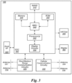
- FIG. 3 illustrates an example simplified block diagram of a communication device 106, according to some embodiments. It is noted that the block diagram of the communication device of FIG. 3 is only one example of a possible communication device.
- communication device 106 may be a user equipment (UE) device, a mobile device or mobile station, a wireless device or wireless station, a desktop computer or computing device, a mobile computing device (e.g., a laptop, notebook, or portable computing device), a tablet and/or a combination of devices, among other devices.
- the communication device 106 may include a set of components 300 configured to perform core functions.
- this set of components may be implemented as a system on chip (SOC), which may include portions for various purposes.
- SOC system on chip
- this set of components 300 may be implemented as separate components or groups of components for the various purposes.
- the set of components 300 may be coupled (e.g., communicatively; directly or indirectly) to various other circuits of the communication device 106.
- the communication device 106 may include various types of memory (e.g., including NAND flash 310), an input/output interface such as connector I/F 320 (e.g., for connecting to a computer system; dock; charging station; input devices, such as a microphone, camera, keyboard; output devices, such as speakers; etc.), the display 360, which may be integrated with or external to the communication device 106, and cellular communication circuitry 330 such as for 5G NR, LTE, GSM, etc., and short to medium range wireless communication circuitry 329 (e.g., Bluetooth TM and WLAN circuitry).
- communication device 106 may include wired communication circuitry (not shown), such as a network interface card, e.g., for Ethernet.
- the cellular communication circuitry 330 may couple (e.g., communicatively; directly or indirectly) to one or more antennas, such as antennas 335 and 336 as shown.
- the short to medium range wireless communication circuitry 329 may also couple (e.g., communicatively; directly or indirectly) to one or more antennas, such as antennas 337 and 338 as shown.
- the short to medium range wireless communication circuitry 329 may couple (e.g., communicatively; directly or indirectly) to the antennas 335 and 336 in addition to, or instead of, coupling (e.g., communicatively; directly or indirectly) to the antennas 337 and 338.
- the short to medium range wireless communication circuitry 329 and/or cellular communication circuitry 330 may include multiple receive chains and/or multiple transmit chains for receiving and/or transmitting multiple spatial streams, such as in a multiple-input multiple output (MIMO) configuration.
- MIMO multiple-input multiple output
- cellular communication circuitry 330 may include dedicated receive chains (including and/or coupled to, e.g., communicatively; directly or indirectly. dedicated processors and/or radios) for multiple radio access technologies (RATs) (e.g., a first receive chain for LTE and a second receive chain for 5G NR).
- RATs radio access technologies
- cellular communication circuitry 330 may include a single transmit chain that may be switched between radios dedicated to specific RATs.
- a first radio may be dedicated to a first RAT, e.g., LTE, and may be in communication with a dedicated receive chain and a transmit chain shared with an additional radio, e.g., a second radio that may be dedicated to a second RAT, e.g., 5G NR, and may be in communication with a dedicated receive chain and the shared transmit chain.
- a first RAT e.g., LTE
- a second radio may be dedicated to a second RAT, e.g., 5G NR, and may be in communication with a dedicated receive chain and the shared transmit chain.
- the communication device 106 may also include and/or be configured for use with one or more user interface elements.
- the user interface elements may include any of various elements, such as display 360 (which may be a touchscreen display), a keyboard (which may be a discrete keyboard or may be implemented as part of a touchscreen display), a mouse, a microphone and/or speakers, one or more cameras, one or more buttons, and/or any of various other elements capable of providing information to a user and/or receiving or interpreting user input.
- the communication device 106 may further include one or more smart cards 345 that include SIM (Subscriber Identity Module) functionality, such as one or more UICC(s) (Universal Integrated Circuit Card(s)) cards 345.
- SIM Subscriber Identity Module
- UICC Universal Integrated Circuit Card
- the SOC 300 may include processor(s) 302, which may execute program instructions for the communication device 106 and display circuitry 304, which may perform graphics processing and provide display signals to the display 360.
- the processor(s) 302 may also be coupled to memory management unit (MMU) 340, which may be configured to receive addresses from the processor(s) 302 and translate those addresses to locations in memory (e.g., memory 306, read only memory (ROM) 350, NAND flash memory 310) and/or to other circuits or devices, such as the display circuitry 304, short range wireless communication circuitry 229, cellular communication circuitry 330, connector I/F 320, and/or display 360.
- the MMU 340 may be configured to perform memory protection and page table translation or set up. In some embodiments, the MMU 340 may be included as a portion of the processor(s) 302.
- the communication device 106 may be configured to communicate using wireless and/or wired communication circuitry.
- the communication device 106 may include hardware and software components for implementing the above features for enabling UE to perform L1-RSRP measurements for beam reporting during SCell activation when the UE does not have precise (and reliable) TCI information available and provides that alternative information as part of the L1-RSRP reporting during SCell activation, as well as the various other techniques described herein.
- the processor 302 of the communication device 106 may be configured to implement part or all of the features described herein, e.g., by executing program instructions stored on a memory medium (e.g., a non-transitory computer-readable memory medium).
- processor 302 may be configured as a programmable hardware element, such as an FPGA (Field Programmable Gate Array), or as an ASIC (Application Specific Integrated Circuit).
- processor 302 of the communication device 106 in conjunction with one or more of the other components 300, 304, 306, 310, 320, 329, 330, 340, 345, 350, 360 may be configured to implement part or all of the features described herein.
- processor 302 may include one or more processing elements.
- processor 302 may include one or more integrated circuits (ICs) that are configured to perform the functions of processor 302.
- each integrated circuit may include circuitry (e.g., first circuitry, second circuitry, etc.) configured to perform the functions of processor(s) 302.
- cellular communication circuitry 330 and short-range wireless communication circuitry 329 may each include one or more processing elements.
- one or more processing elements may be included in cellular communication circuitry 330 and, similarly, one or more processing elements may be included in short range wireless communication circuitry 329.
- cellular communication circuitry 330 may include one or more integrated circuits (ICs) that are configured to perform the functions of cellular communication circuitry 330.
- each integrated circuit may include circuitry (e.g., first circuitry, second circuitry, etc.) configured to perform the functions of cellular communication circuitry 230.
- the short-range wireless communication circuitry 329 may include one or more ICs that are configured to perform the functions of short-range wireless communication circuitry 32.
- each integrated circuit may include circuitry (e.g., first circuitry, second circuitry, etc.) configured to perform the functions of short-range wireless communication circuitry 329.
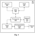
- FIG. 4 illustrates an example block diagram of a base station 102, according to some embodiments. It is noted that the base station of FIG. 4 is merely one example of a possible base station. As shown, the base station 102 may include processor(s) 404 which may execute program instructions for the base station 102. The processor(s) 404 may also be coupled to memory management unit (MMU) 440, which may be configured to receive addresses from the processor(s) 404 and translate those addresses to locations in memory (e.g., memory 460 and read only memory (ROM) 450) or to other circuits or devices.
- MMU memory management unit
- the base station 102 may include at least one network port 470.
- the network port 470 may be configured to couple to a telephone network and provide a plurality of devices, such as UE devices 106, access to the telephone network as described above in FIGS. 1 and 2 .
- the network port 470 may also or alternatively be configured to couple to a cellular network, e.g., a core network of a cellular service provider.
- the core network may provide mobility related services and/or other services to a plurality of devices, such as UE devices 106.
- the network port 470 may couple to a telephone network via the core network, and/or the core network may provide a telephone network (e.g., among other UE devices serviced by the cellular service provider).
- base station 102 may be a next generation base station, e.g., a 5G New Radio (5G NR) base station, or "gNB".
- base station 102 may be connected to a legacy evolved packet core (EPC) network and/or to a NR core (NRC) network.
- EPC legacy evolved packet core
- NRC NR core
- base station 102 may be considered a 5G NR cell and may include one or more transition and reception points (TRPs).
- TRPs transition and reception points
- a UE capable of operating according to 5G NR may be connected to one or more TRPs within one or more gNBs.
- the base station 102 may include at least one antenna 434, and possibly multiple antennas.
- the at least one antenna 434 may be configured to operate as a wireless transceiver and may be further configured to communicate with UE devices 106 via radio 430.
- the antenna 434 communicates with the radio 430 via communication chain 432.
- Communication chain 432 may be a receive chain, a transmit chain or both.
- the radio 430 may be configured to communicate via various wireless communication standards, including, but not limited to, 5G NR, LTE, LTE-A, GSM, UMTS, CDMA2000, Wi-Fi, etc.
- the base station 102 may be configured to communicate wirelessly using multiple wireless communication standards.
- the base station 102 may include multiple radios, which may enable the base station 102 to communicate according to multiple wireless communication technologies.
- the base station 102 may include an LTE radio for performing communication according to LTE as well as a 5G NR radio for performing communication according to 5G NR.
- the base station 102 may be capable of operating as both an LTE base station and a 5G NR base station.
- the base station 102 may include a multi-mode radio which is capable of performing communications according to any of multiple wireless communication technologies (e.g., 5G NR and Wi-Fi, LTE and Wi-Fi, LTE and UMTS, LTE and CDMA2000, UMTS and GSM, etc.).
- multiple wireless communication technologies e.g., 5G NR and Wi-Fi, LTE and Wi-Fi, LTE and UMTS, LTE and CDMA2000, UMTS and GSM, etc.
- the BS 102 may include hardware and software components for implementing or supporting implementation of features described herein.
- the processor 404 of the base station 102 may be configured to implement or support implementation of part or all of the methods described herein, e.g., by executing program instructions stored on a memory medium (e.g., a non-transitory computer-readable memory medium).
- the processor 404 may be configured as a programmable hardware element, such as an FPGA (Field Programmable Gate Array), or as an ASIC (Application Specific Integrated Circuit), or a combination thereof.
- processor 404 of the BS 102 in conjunction with one or more of the other components 430, 432, 434, 440, 450, 460, 470 may be configured to implement or support implementation of part or all of the features described herein.
- processor(s) 404 may be comprised of one or more processing elements. In other words, one or more processing elements may be included in processor(s) 404. Thus, processor(s) 404 may include one or more integrated circuits (ICs) that are configured to perform the functions of processor(s) 404. In addition, each integrated circuit may include circuitry (e.g., first circuitry, second circuitry, etc.) configured to perform the functions of processor(s) 404.
- circuitry e.g., first circuitry, second circuitry, etc.
- radio 430 may be comprised of one or more processing elements.
- one or more processing elements may be included in radio 430.
- radio 430 may include one or more integrated circuits (ICs) that are configured to perform the functions of radio 430.
- each integrated circuit may include circuitry (e.g., first circuitry, second circuitry, etc.) configured to perform the functions of radio 430.
- FIG. 5 Block Diagram of Cellular Communication Circuitry
- FIG. 5 illustrates an example simplified block diagram of cellular communication circuitry, according to some embodiments. It is noted that the block diagram of the cellular communication circuitry of FIG. 5 is only one example of a possible cellular communication circuit.
- cellular communication circuitry 330 may be include in a communication device, such as communication device 106 described above.
- communication device 106 may be a user equipment (UE) device, a mobile device or mobile station, a wireless device or wireless station, a desktop computer or computing device, a mobile computing device (e.g., a laptop, notebook, or portable computing device), a tablet and/or a combination of devices, among other devices.
- UE user equipment
- the cellular communication circuitry 330 may couple (e.g., communicatively; directly or indirectly) to one or more antennas, such as antennas 335 a-b and 336 as shown (in FIG. 3 ).
- cellular communication circuitry 330 may include dedicated receive chains (including and/or coupled to, e.g., communicatively; directly or indirectly. dedicated processors and/or radios) for multiple RATs (e.g., a first receive chain for LTE and a second receive chain for 5G NR).
- cellular communication circuitry 330 may include a modem 510 and a modem 520.
- Modem 510 may be configured for communications according to a first RAT, e.g., such as LTE or LTE-A
- modem 520 may be configured for communications according to a second RAT, e.g., such as 5GNR.
- modem 510 may include one or more processors 512 and a memory 516 in communication with processors 512. Modem 510 may be in communication with a radio frequency (RF) front end 530.
- RF front end 530 may include circuitry for transmitting and receiving radio signals.
- RF front end 530 may include receive circuitry (RX) 532 and transmit circuitry (TX) 534.
- receive circuitry 532 may be in communication with downlink (DL) front end 550, which may include circuitry for receiving radio signals via antenna 335a.
- DL downlink
- modem 520 may include one or more processors 522 and a memory 526 in communication with processors 522. Modem 520 may be in communication with an RF front end 540.
- RF front end 540 may include circuitry for transmitting and receiving radio signals.
- RF front end 540 may include receive circuitry 542 and transmit circuitry 544.
- receive circuitry 542 may be in communication with DL front end 560, which may include circuitry for receiving radio signals via antenna 335b.
- a switch 570 may couple transmit circuitry 534 to uplink (UL) front end 572.
- switch 570 may couple transmit circuitry 544 to UL front end 572.
- UL front end 572 may include circuitry for transmitting radio signals via antenna 336.
- switch 570 may be switched to a first state that allows modem 510 to transmit signals according to the first RAT (e.g., via a transmit chain that includes transmit circuitry 534 and UL front end 572).
- switch 570 may be switched to a second state that allows modem 520 to transmit signals according to the second RAT (e.g., via a transmit chain that includes transmit circuitry 544 and UL front end 572).
- the modem 510 may include hardware and software components for implementing the above features or for enabling UE to perform L1-RSRP measurements for beam reporting during SCell activation when the UE does not have precise (and reliable) TCI information available and provides that alternative information as part of the L1-RSRP reporting during SCell activation, as well as the various other techniques described herein.
- the processors 512 may be configured to implement part or all of the features described herein, e.g., by executing program instructions stored on a memory medium (e.g., a non-transitory computer-readable memory medium).
- processor 512 may be configured as a programmable hardware element, such as an FPGA (Field Programmable Gate Array), or as an ASIC (Application Specific Integrated Circuit).
- processor 512 in conjunction with one or more of the other components 530, 532, 534, 550, 570, 572, 335 and 336 may be configured to implement part or all of the features described herein.
- processors 512 may include one or more processing elements.
- processors 512 may include one or more integrated circuits (ICs) that are configured to perform the functions of processors 512.
- each integrated circuit may include circuitry (e.g., first circuitry, second circuitry, etc.) configured to perform the functions of processors 512.
- the modem 520 may include hardware and software components for implementing the above features for enabling UE to perform L1-RSRP measurements for beam reporting during SCell activation when the UE does not have precise (and reliable) TCI information available and provides that alternative information as part of the L1-RSRP reporting during SCell activation, as well as the various other techniques described herein.
- the processors 522 may be configured to implement part or all of the features described herein, e.g., by executing program instructions stored on a memory medium (e.g., a non-transitory computer-readable memory medium).
- processor 522 may be configured as a programmable hardware element, such as an FPGA (Field Programmable Gate Array), or as an ASIC (Application Specific Integrated Circuit).
- processor 522 in conjunction with one or more of the other components 540, 542, 544, 550, 570, 572, 335 and 336 may be configured to implement part or all of the features described herein.
- processors 522 may include one or more processing elements.
- processors 522 may include one or more integrated circuits (ICs) that are configured to perform the functions of processors 522.
- each integrated circuit may include circuitry (e.g., first circuitry, second circuitry, etc.) configured to perform the functions of processors 522.
- SCell activation and deactivation are used to activate or deactivate, respectively, data transmission between a UE and a SCell. In some embodiments, this occurs while the SCell is in carrier aggregation. Note that this occurs in one or more wireless standards including, for example, 5G NR.
- the carrier aggregation is set up by a Radio Resource Control (RRC) process, and after the RRC process has finished, the data transmission is switched on/off by the UE to facilitate activation/deactivation of the SCell.
- RRC Radio Resource Control
- the time to complete the SCell activation is based on a number of different factors and the SCell activation may be delayed for one or more reasons.
- the delay is specified as based on whether the SCell being activated belongs to FR2 and whether there is no active serving cell on that FR2 band provided that PCell or PSCell is Frequency Range 1 (FR1).
- the FR2 SCell activation delay is based on whether the target SCell is known to the UE.
- SCell activation time, T activation_time may be represented as: 8 ms + 24 * T rs + T uncertainty _ MAC + T L 1 ⁇ RSRP , measure + T L 1 ⁇ RSRP ,report + T HARQ + T FineTiming and if the target SCell is unknown to UE and periodic CSI-RS is used for CSI reporting, provided that the side condition ⁇ s/Iot ⁇ [-2]dB is fulfilled, then T activation_time is: 3 ms + 24 * T rs + T L 1 ⁇ RSRP , measure + T L 1 ⁇ RSRP , report + max T HARQ + T uncertainty _ MAC + 5 ms + T FineTiming T uncertainity _ RRC + T R
- the TCI information for L1-RSRP RS may be unknown to the UE. If that occurs, the network may not configure any TCI information for L1-RSRP RS before the SCell activation begins or the network may configure TCI information for L1-RSRP RS before the SCell activation begins, but that TCI-related measurement was long time ago and now is out of date. In these cases, the UE needs to obtain the TCI for L1-RSRP after cell synchronization. This problem may be better understood by explaining a SCell activation process.
- FIG. 6 is a data flow diagram of a SCell activation process according to some embodiments.
- the activation process occurs after the SCell has been added to the UE.
- the SCell activation process begins by the UE receiving a MAC control element (CE) command in a message from the network to activate an SCell (processing block 601) and decodes the message to determine that a targeted SCell is to be activated (processing block 602).
- CE MAC control element
- the UE After decoding the message, the UE begins the process of activating the SCell by tuning (or retuning) its RF to the new SCell (processing block 603).
- the tuning operation ensures that the UE's RF filter covers the new SCell.
- the UE performs SCell synchronization.
- SCell synchronization the UE synchronizes with the target SCell to obtain timing information needed for communication (processing block 604). In some embodiments, this timing information comprises frame boundary and symbol boundary information.
- the UE After synching to the SCell, the UE performs L1-RSRP measurements that can be used by the network to identify the best beam pair to use to enable to support channel state information (CSI) reporting for the UE (processing block 605).
- CSI channel state information
- the UE After performing the L1-RSRP measurements, the UE knows the best receive beam that it can use with the SCell to receive one of the SS blocks for which it measured.
- this process assumes that the UE has been configured with the TCI information that provides beam information that the UE uses for the measurements. Without precise TCI information, the UE cannot perform reliable L1-RSRP measurements and thus makes any reporting of such measurements unreliable.
- the UE does not have reliable TCI information if the SCell being activated, referred to herein as the target SCell, belongs to FR2 and if there is not active serving cell on that FR2 band provided that PCell or PSCell is FR1.
- the UE also does not have reliable TCI information if the target SCell is unknown to the UE and either semi-persistent CSI-RS or periodic CSI-RS is used for CSI reporting.
- the UE After the UE has completed the measurements, the UE sends a L1-RSRP measurement report to the network (processing block 606).
- this report includes the measurements of all SSBs for which the UE made measurements.
- the network knows the reference signal that is best to use as it indicates the SS block with the highest response for the UE.
- the report specifies information (e.g., an index) identifying the best SS block based on the measured RSRP for the particular SS block. Using this information, the network can determine the transmit (Tx) beam that the network should use to transmit the CSI, as well as the SS block, to the UE.
- Tx transmit
- the L1-RSRP measurement report allows the UE and the network to know the best receive and transmit pair to use for the link between the UE and the SCell.
- the network configures the UE for the CQI reporting resource, or reference signal, and the CSI-RS using the best beam pair. This is done by the network sending sends MAC CE command messages that are received by the UE (processing block 607). Subsequently, HARQ processing (processing block 608) and the MAC CE processing (processing block 608) decode and execute those commands to activate the channel TCI and CSI-RS for the UE. Note that even though the UE does not provide usable CQI until after SCell activation has been completed, the UE has been providing CQI during the SCell activation process since RF turning of processing block 603 but this reported CQI only indicates that the UE is out of range of the SCell. The UE keeps reporting the CQI indicating an out of range status until finished activation
- the UE After decoding and beginning the execution of the commands for activating the channel TCI and the CSI-RS, the UE performs fine time tracking (processing block 610). In some embodiments, the fine time tracking performs time frequency checking to obtain a timing frequency offset of the target reference signal.
- the UE activates the CQI reporting based on the activated CSI-RS (processing block 611). This enables the UE to take measurements of the CQI of targeted CSI-RS and report them.
- the UE because the UE does not have precise TCI information, the UE cannot perform a reliable L1-RSRP measurements for beam reporting, thereby making the L1-RSRP report from the UE unreliable.
- the UE uses alternative information as a replacement to LI-RSRP measurements when precise (and reliable) TCI information is not available and provides that alternative information as part of the L1-RSRP reporting during SCell activation.
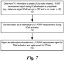
- FIG. 7 is a flow diagram of a process for using alternative information in the L1-RSRP reporting during SCell activation.
- the process includes determining, during secondary cell (SCell) activation, that beam information to enable a user equipment (UE) to make a reliable L1-RSRP measurement is unavailable (processing block 701).
- the beam information that is not available is reliable TCI information (e.g., TCI information of a certain quality level to make a reliable L1-RSRP measurement report).
- alternative information in used by the UE for the L1-RSRP measurements during SCell activation (processing block 702). In some embodiments, this information is obtained after SCell synchronization.
- the UE reports the alternative information in a L1-RSRP measurement report for the SCell activation as a replacement when the beam information to enable the UE to make a reliable L1-RSRP measurement is unavailable (processing block 703).
- the beam information to enable the UE to make the reliable L1-RSRP measurement report is unavailable when the SCell being activated belongs to Frequency Range 2 (FR2) and that the SCell is unknown to the UE, and in that case the alternative information is provided in the L1-RSRP measurement report as the replacement.
- FR2 Frequency Range 2
- the replacement information comprises information of one or more Synchronization Signal Blocks (SSBs), and the reporting of the alternative information comprises reporting the information of the one or more SSBs as the replacement.
- the alternative information comprise L1-RSRP measurements based on L3 SSB measurement information, and the reporting of the alternative information comprises reporting L1-RSRP measurements based on L3 SSB measurement information as the replacement.
- the alternative information is related to preconfigured TCI information for L1-RSRP that is preconfigured by a network as part of the SCell activation process, and the preconfigured TCI information is used for L1-RSRP measurements.
- the alternative information used by the LTE using information from Synchronization Signal Blocks (SSBs) for the L1-RSRP measurement. That is, the LTE uses an SSB-based L1-RSRP measurement during SCell activation.
- the UE uses SSBs that are used for SCell synchronization when the UE is synchronizing with the target SCell.
- SSBs Synchronization Signal Blocks
- the UE uses only SSBs to perform the L1-RSRP measurement during the current SCell activation. In some embodiments, these SSBs are the ones used for SCell synchronization in the current SCell activation.
- FIG. 8 is a data flow diagram of some embodiments of a SCell activation process that uses detectable SSBs detected for the L1-RSRP measurement report when reliable beam information (e.g., TCI information) is not available for L1-RSRP measurements.
- reliable beam information e.g., TCI information
- the UE identifies detectable SSBs (processing block 801).
- the UE uses the SSBs that are detected for the L1-RSRP measurement for beam pair refinement. Thereafter, the UE reports the L1-RSRP measurements for the SSBs (processing block 801). In some embodiments, one or more SSBs that were not detected will still have a measurement reported. In some embodiments, the measurement is reported as zero or some other information is provided to indicate that the beams associated with the SSB should not be used for communication between the UE and the target SCell. In some embodiments, the L1-RSRP report identifies the best receive beam for each detectable SSB reception.
- FIG. 9 is a flow diagram of the process of using detectable SSBs that are detected for the L1-RSRP measurement in the SCell activation process when reliable beam information (e.g., TCI information) is not available for L1-RSRP measurements during SCell activation.
- reliable beam information e.g., TCI information
- the UE uses L1-RSRP RS TCI that is based on the layer three (L3) SSB measurements.
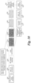
- FIG. 10 is a data flow diagram of some embodiments of a SCell activation process that uses L3 SSB measurements made during SCell activation to create TCI that is used for L1-RSRP when reliable beam information (e.g., TCI information) is not available for L1-RSRP measurements during SCell activation.
- the process of FIG. 10 is the same as that of FIG. 6 except where as shown and discussed herein.
- the SCell activation process includes additional operations to provide SSB measurement results to the network that are used by the network to determine the proper TCI for the L1-RSRP RS measurements. More specifically, after SCell synchronization, the UE performs a process to perform L3 SSB measurements and reports the results to the network (processing block 1001). As part of the L3 SSB measurement, the UE measures the detected SSBs in the SCell synchronization step and reports the measurement results with an SSB index to the network. In some embodiments, this measurement is requested by network.
- the UE waits for the network to configure or otherwise activate the TCI that enables the UE to perform L1-RSRP measurements and L1-RSRP measurement reporting to the network.
- the network configures or activates proper TCI for L1-RSRP RS based on the SSB measurement (processing block 1002).
- the L1-RSRP RS is a QCL type D with certain SSBs.
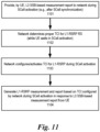
- FIG. 11 is a flow diagram of the process of using L3 SSB measurement and reporting for configuring the UE with TCI during SCell activation to enable the UE to perform L1-RSRP measurement and reporting during the SCell activation process when reliable beam information (e.g., TCI information) is not available for L1-RSRP measurements during SCell activation.
- reliable beam information e.g., TCI information
- the SCell activation process is augmented to preconfigure TCI information for all L1-RSRP RS.
- FIG. 12 is a data flow diagram of some embodiments of a SCell activation process that uses preconfigures beam information (e.g., TCI information) for RSRP RS during SCell activation to provide TCI that is used for L1-RSRP when reliable beam information (e.g., TCI information) is not available for L1-RSRP measurements during SCell activation.
- the process of FIG. 12 is the same as that of FIG. 6 except where as shown and discussed herein.
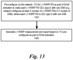
- the network preconfigures TCIs for each L1-RSRP RS (processing block 1201). In some embodiments, the network preconfigures TCIs for each L1-RSRP RS where the number of L1-RSRP RS is not less than the number of SSBs transmitted in that SCell. Thus, if there is a predetermined number of SSBs (e.g., greater than zero) transmitted in that SCell, then the network configure at least that same number of L1-RSRP RSs. In some embodiments, each of those L1-RSRP RS is a QCL type D with one SSB.
- FIG. 13 is a flow diagram of the process of pre-configuring a UE with beam information (e.g., TCI information) during SCell activation for the UE to perform L1-RSRP measurement and reporting during the SCell activation process when reliable beam information (e.g., TCI information) is not available for L1-RSRP measurements during SCell activation.
- beam information e.g., TCI information
- Example 1 is a baseband processor of a user equipment (UE) configured to perform operations comprising: determining, during secondary cell (SCell) activation, that beam information to enable the UE to make a reliable layer 1 (L1)-Reference Signal Received Power (RSRP) measurement is unavailable; performing, when the beam information to enable the UE to make the reliable L1-RSRP measurement is unavailable, the L1-RSRP measurement using information of one or more Synchronization Signal Blocks (SSBs) during the SCell activation, wherein performing the L1-RSRP measurement using information of one or more SSBs during the SCell activation comprises identifying, by the UE, one or more detectable SSBs during the SCell activation and using information of the one or more detectable SSBs for the L1-RSRP measurement; and reporting, by the UE after SCell synchronization, the L1-RSRP measurement using information of one or more SSBs in a L1-RSRP measurement report for the SCell activation as a replacement.
- SCell
- Example 2 is the baseband processor of example 1 that may optionally include that reporting of the alternative information comprises reporting, by the UE, the L1-RSRP with an SSB index associated with each measurement.
- Example 3 is the baseband processor of example 1 that may optionally include that reporting the alternative information comprises identifying one receive beam for each detectable SSB reception that is determined to have a better quality than all other receive beams for said each detectable SSB reception.
- Example 4 is the baseband processor of example 1 that may optionally include that determining, during SCell activation, that beam information to enable the UE to make the reliable L1-RSRP measurement report is unavailable comprises determining the SCell being activated belongs to Frequency Range 2 (FR2) and that the SCell is unknown to the UE.
- FR2 Frequency Range 2
- Example 5 is the baseband processor of example 4 that may optionally include that the alternative information is provided in the L1-RSRP measurement report as the replacement when the SCell being activated belongs to FR2 and the SCell is unknown to the UE.
- Example 6 is the baseband processor of example 1 that may optionally include that the alternative information is used as a replacement when transmission configuration indicator (TCI) information of a certain quality level is not available to enable the UE to make a reliable L1-RSRP measurement report.
- TCI transmission configuration indicator
- Example 7 is the baseband processor of example 1 that may optionally include that identifying the one or more detectable SSBs during the SCell activation comprises using SSBs that are used for SCell synchronization when the UE is synchronizing with a target SCell.
- Example 8 is a method to acquire TCI information for secondary cell (SCell) activation, the method comprising: determining, during secondary cell (SCell) activation, that beam information to enable a user equipment (UE) to make a reliable L1-RSRP measurement is unavailable; performing, when the beam information to enable the LTE to make the reliable L1-RSRP measurement is unavailable, the L1-RSRP measurement using information of one or more Synchronization Signal Blocks (SSBs) during the SCell activation, wherein performing the L1-RSRP measurement using information of one or more SSBs during the SCell activation comprises identifying, by the UE, one or more detectable SSBs during the SCell activation, and using information of the one or more detectable SSBs for the L1-RSRP measurement; and reporting, by the UE after SCell synchronization, the L1-RSRP measurement using information of one or more SSBs in a L1-RSRP measurement report for the SCell activation as a replacement.
- SSBs Syn
- Example 9 is the method of example 8 that may optionally include that the reporting of the alternative information comprises reporting, by the UE, the L1-RSRP with an SSB index associated with each measurement.
- Example 10 is the method of example 8 that may optionally include that reporting the alternative information comprises identifying one receive beam for each detectable SSB reception that is determined to have a better quality than all other receive beams for said each detectable SSB reception.
- Example 11 is the method of example 8 that may optionally include that determining, during SCell activation, that beam information to enable the UE to make the reliable L1-RSRP measurement report is unavailable comprises determining the SCell being activated belongs to Frequency Range 2 (FR2) and that the SCell is unknown to the UE.
- FR2 Frequency Range 2
- Example 12 is the method of example 11 that may optionally include that the alternative information is provided in the L1-RSRP measurement report as the replacement when the SCell being activated belongs to FR2 and the SCell is unknown to the UE.
- Example 13 is the method of example 8 that may optionally include that the alternative information is used as a replacement when transmission configuration indicator (TCI) information of a certain quality level is not available to enable the UE to make a reliable L1-RSRP measurement report.
- TCI transmission configuration indicator
- Example 14 is the method of example 8 that may optionally include that identifying the one or more detectable SSBs during the SCell activation comprises using SSBs that are used for SCell synchronization when the UE is synchronizing with a target SCell.
- Example 15 is a UE device comprising: at least one antenna; at least one radio, wherein the at least one radio is to perform cellular communications using a radio access technology that establishes a wireless link with a base station; and one or more processors to: determine, during secondary cell (SCell) activation, that beam information to enable a user equipment (UE) to make a reliable L1-RSRP measurement is unavailable; perform, when the beam information to enable the UE to make the reliable L1-RSRP measurement is unavailable the L1-RSRP measurement using information of one or more Synchronization Signal Blocks (SSBs) during the SCell activation, wherein the one or more processors perform the L1-RSRP measurement using information of one or more SSBs during the SCell activation by identifying, by the UE, one or more detectable SSBs during the SCell activation and using information of the one or more detectable SSBs for the L1-RSRP measurement; and report, by the UE after SCell synchronization, the L1-RSRP
- Example 16 is the UE device of example 15 that may optionally include that the one or more processors report of the alternative information by reporting the L1-RSRP with an SSB index associated with each measurement.
- Example 17 is the UE device of example 15 that may optionally include that the one or more processors report the alternative information by identifying one receive beam for each detectable SSB reception that is determined to have a better quality than all other receive beams for said each detectable SSB reception.
- Example 18 is the UE device of example 15 that may optionally include that determining, during SCell activation, that beam information to enable the UE to make the reliable L1-RSRP measurement report is unavailable comprises determining the SCell being activated belongs to Frequency Range 2 (FR2) and that the SCell is unknown to the UE.
- FR2 Frequency Range 2
- Example 19 is the UE device of example 18 that may optionally include that the alternative information is provided in the L1-RSRP measurement report as the replacement when the SCell being activated belongs to FR2 and the SCell is unknown to the UE.
- Example 20 is the UE device of example 15 that may optionally include that the alternative information is used as a replacement when transmission configuration indicator (TCI) information of a certain quality level is not available to enable the UE to make a reliable L1-RSRP measurement report.
- TCI transmission configuration indicator
- Example 21 is a baseband processor configured to perform operations comprising: determining, during secondary cell (SCell) activation, that beam information to enable a user equipment (UE) to make a reliable layer 1 (L1)-Reference Signal Received Power (RSRP) measurement is unavailable; performing, when the beam information to enable the UE to make the reliable L1-RSRP measurement is unavailable, the L1-RSRP measurement using preconfigured TCI information for L1-RSRP that is preconfigured by a network during the SCell activation; and reporting, by the UE after SCell synchronization, L1-RSRP measurement using the preconfigured TCI information in a L1-RSRP measurement report for the SCell activation as a replacement.
- SCell secondary cell
- RSRP Reference Signal Received Power
- Example 22 is the baseband processor of example 21 that may optionally include that the operations further comprise configuring, by the network, at least a portion of L1-RSRP reference signals (RSs) and each L1-RSRP RS is QCL type D with one SSB.
- RSs L1-RSRP reference signals
- Example 23 is a method to acquire TCI information for secondary cell (SCell) activation, the method comprising: determining, during secondary cell (SCell) activation, that beam information to enable a user equipment (UE) to make a reliable L1-RSRP measurement is unavailable; performing, when the beam information to enable the UE to make the reliable L1-RSRP measurement is unavailable, the L1-RSRP measurement using preconfigured TCI information for L1-RSRP that is preconfigured by a network during the SCell activation and reporting, by the UE after SCell synchronization, L1-RSRP measurement using the preconfigured TCI information in a L1-RSRP measurement report for the SCell activation as a replacement.
- SCell secondary cell
- Example 24 is the method of example 23 that may optionally include configuring, by the network, at least a portion of L1-RSRP reference signals (RSs) and each L1-RSRP RS is QCL type D with one SSB.
- RSs L1-RSRP reference signals
- Example 25 is a UE device comprising: at least one antenna; at least one radio, wherein the at least one radio is to perform cellular communications using a radio access technology that establishes a wireless link with a base station; and one or more processors to: determine, during secondary cell (SCell) activation, that beam information to enable a user equipment (UE) to make a reliable L1-RSRP measurement is unavailable; perform, when the beam information to enable the UE to make the reliable L1-RSRP measurement is unavailable, the L1-RSRP measurement using preconfigured TCI information for L1-RSRP that is preconfigured by a network during the SCell activation; and report, by the UE after SCell synchronization, L1-RSRP measurement using the preconfigured TCI information in a L1-RSRP measurement report for the SCell activation as a replacement.
- SCell secondary cell
- UE user equipment
- Example 26 is the UE device of example 25 that may optionally include that the network configures at least a portion of L1-RSRP reference signals (RSs) and each L1-RSRP RS is QCL type D with one SSB.
- RSs L1-RSRP reference signals
- Portions of what was described above may be implemented with logic circuitry such as a dedicated logic circuit or with a microcontroller or other form of processing core that executes program code instructions.
- logic circuitry such as a dedicated logic circuit or with a microcontroller or other form of processing core that executes program code instructions.
- program code such as machine-executable instructions that cause a machine that executes these instructions to perform certain functions.
- a “machine” may be a machine that converts intermediate form (or “abstract") instructions into processor specific instructions (e.g., an abstract execution environment such as a "virtual machine” (e.g., a Java Virtual Machine), an interpreter, a Common Language Runtime, a high-level language virtual machine, etc.), and/or, electronic circuitry disposed on a semiconductor chip (e.g., "logic circuitry” implemented with transistors) designed to execute instructions such as a general-purpose processor and/or a special-purpose processor. Processes taught by the discussion above may also be performed by (in the alternative to a machine or in combination with a machine) electronic circuitry designed to perform the processes (or a portion thereof) without the execution of program code.
- processor specific instructions e.g., an abstract execution environment such as a "virtual machine” (e.g., a Java Virtual Machine), an interpreter, a Common Language Runtime, a high-level language virtual machine, etc.
- the present invention also relates to an apparatus for performing the operations described herein.
- This apparatus may be specially constructed for the required purpose, or it may comprise a general-purpose computer selectively activated or reconfigured by a computer program stored in the computer.
- a computer program may be stored in a computer readable storage medium, such as, but is not limited to, any type of disk including floppy disks, optical disks, CD-ROMs, and magnetic-optical disks, read-only memories (ROMs), RAMs, EPROMs, EEPROMs, magnetic or optical cards, or any type of media suitable for storing electronic instructions, and each coupled to a computer system bus.
- a machine-readable medium includes any mechanism for storing or transmitting information in a form readable by a machine (e.g., a computer).
- a machine-readable medium includes read only memory ("ROM”); random access memory (“RAM”); magnetic disk storage media; optical storage media; flash memory devices; etc.
- An article of manufacture may be used to store program code.
- An article of manufacture that stores program code may be embodied as, but is not limited to, one or more memories (e.g., one or more flash memories, random access memories (static, dynamic or other)), optical disks, CD-ROMs, DVD ROMs, EPROMs, EEPROMs, magnetic or optical cards or other type of machine-readable media suitable for storing electronic instructions.
- Program code may also be downloaded from a remote computer (e.g., a server) to a requesting computer (e.g., a client) by way of data signals embodied in a propagation medium (e.g., via a communication link (e.g., a network connection)).
- personally identifiable information should follow privacy policies and practices that are generally recognized as meeting or exceeding industry or governmental requirements for maintaining the privacy of users.
- personally identifiable information data should be managed and handled so as to minimize risks of unintentional or unauthorized access or use, and the nature of authorized use should be clearly indicated to users.
Abstract
Description
- The present application is a non-provisional application of and claims the benefit of
U.S. Provisional Patent Application No. 63/007,234, filed April 8, 2020 - Embodiments relates generally to wireless technology and more particularly to the transmission configuration indicator (TCI) information for secondary cell (SCell) activation in a wireless communication system.
- Wireless communication systems provide various telecommunication services and typically employ multiple-access technologies capable of supporting communication with multiple users by sharing available system resources. Multiple-access technologies include, for example, code division multiple access (CDMA) systems, time division multiple access (TDMA) systems, frequency division multiple access (FDMA) systems, orthogonal frequency division multiple access (OFDMA) systems, single-carrier frequency division multiple access (SC-FDMA) systems, and time division synchronous code division multiple access (TD-SCDMA) systems.
- These multiple access technologies have been adopted in various telecommunication standards to provide a common protocol for enabling different wireless devices to communicate. One such standard is 5th Generation (5G) New Radio (NR), which includes some aspects that may be based on the Long-Term Evolution (LTE) standard. However, further advancements are still needed in the technology for 5G NR.
- One such aspect involves the activation delay related to a secondary cell (SCell) in cases where a SCell being activated belongs to Frequency Range 2 (FR2) and if there is no active serving cell on that FR2 band provided that a primary cell (PCell) or primary secondary cell (PSCell) is Frequency Range 1 (FR1). In the activation procedure, beam information (e.g., the transmission configuration indicator (TCI) information) used for Layer 1 (L1)-Reference Signal Received Power (RSRP) reporting (L1-RSRP) reference signal (RS) is unknown to the user equipment (UE). In such a case, the network may not configure any TCI information for L1-RSRP RS before beginning the process of activating the SCell or may configure TCI information for L1-RSRP RS beginning the process of activating the SCell, but that TCI related information was made a long time ago and is now out of date. Without precise TCI information, the UE cannot perform a reliable L1-RSRP, thereby making the L1-RSRP report unreliable. If the L1-RSRP is unreliable, the process of SCell activation for an FR2 unknown cell is delayed.
- A method and apparatus of a device that acquires transmission configuration indicator (TCI) information for secondary cell (SCell) activation. In some embodiments, the TCI information is acquired for SCell activation by: determining, during secondary cell (SCell) activation, that beam information (e.g., TCI information) to enable a user equipment (LTE) to make a reliable layer 1 (L1)-Reference Signal Received Power (RSRP) measurement report is unavailable; performing the L1-RSRP measurement using information of one or more Synchronization Signal Blocks (SSBs) during the SCell activation, wherein the one or more processors perform the L1-RSRP measurement using information of one or more SSBs during the SCell activation by identifying, by the UE, one or more detectable SSBs during the SCell activation and using information of the one or more detectable SSBs for the L1-RSRP measurement, and reporting, by the UE after SCell synchronization, alternative information in the L1-RSRP measurement report for the SCell activation as a replacement when the beam information to enable the UE to make the reliable L1-RSRP measurement report is unavailable.
- Other methods and apparatuses are also described.
- The present invention is illustrated by way of example and not limitation in the figures of the accompanying drawings in which like references indicate similar elements.
-
FIG. 1 illustrates an example wireless communication system according to some embodiments. -
FIG. 2 illustrates a base station (BS) in communication with a user equipment (UE) device according to some embodiments. -
FIG. 3 illustrates an example block diagram of a UE according to some embodiments. -
FIG. 4 illustrates an example block diagram of a BS according to some embodiments. -
FIG. 5 illustrates an example block diagram of cellular communication circuitry, according to some embodiments. -
FIG. 6 is a data flow diagram of a SCell activation process according to some embodiments. -
FIG. 7 is a flow diagram of a process for using alternative information in the L1-RSRP reporting during SCell activation. -
FIG. 8 is a data flow diagram of some embodiments of a SCell activation process that uses using detectable SSBs detected for the L1-RSRP measurement report when reliable beam information (e.g., TCI information) is not available for L1-RSRP measurements. -
FIG. 9 is a flow diagram of the process of using detectable SSBs that are detected for the L1-RSRP measurement in the SCell activation process when reliable beam information (e.g., TCI information) is not available for L1-RSRP measurements during SCell activation. -
FIG. 10 is a data flow diagram of some embodiments of a SCell activation process that uses L3 SSB measurements made during SCell activation to create TCI that is used for L1-RSRP when reliable beam information (e.g., TCI information) is not available for L1-RSRP measurements during SCell activation. -
FIG. 11 is a flow diagram of the process of using L3 SSB measurement and reporting for configuring the LTE with TCI during SCell activation to enable the UE to perform L1-RSRP measurement and reporting during the SCell activation process when reliable beam information (e.g., TCI information) is not available for L1-RSRP measurements during SCell activation. -
FIG. 12 is a data flow diagram of some embodiments of a SCell activation process that uses preconfigures beam information (e.g., TCI information) for RSRP RS during SCell activation to provide TCI that is used for L1-RSRP when reliable beam information (e.g., TCI information) is not available for L1-RSRP measurements during SCell activation. -
FIG. 13 is a flow diagram of the process of pre-configuring a UE with beam information (e.g., TCI information) during SCell activation for the UE to perform L1-RSRP measurement and reporting during the SCell activation process when reliable beam information (e.g., TCI information) is not available for L1-RSRP measurements during SCell activation. - A method and apparatus of a device that acquires beam information (e.g., transmission configuration indicator (TCI) information) for secondary cell (SCell) activation when the beam information to enable a user equipment (UE) to make a reliable beam measurement report is unavailable. It will be apparent, however, to one skilled in the art, that embodiments of the present invention may be practiced without these specific details. In other instances, well-known components, structures, and techniques have not been shown in detail in order not to obscure the understanding of this description.
- Reference in the specification to "one embodiment" or "an embodiment" means that a particular feature, structure, or characteristic described in connection with the embodiment can be included in at least one embodiment of the invention. The appearances of the phrase "in one embodiment" in various places in the specification do not necessarily all refer to the same embodiment.
- In the following description and claims, the terms "coupled" and "connected," along with their derivatives, may be used. It should be understood that these terms are not intended as synonyms for each other. "Coupled" is used to indicate that two or more elements, which may or may not be in direct physical or electrical contact with each other, co-operate or interact with each other. "Connected" is used to indicate the establishment of communication between two or more elements that are coupled with each other.
- The processes depicted in the figures that follow, are performed by processing logic that comprises hardware (e.g., circuitry, dedicated logic, etc.), software (such as is run on a general-purpose computer system or a dedicated machine), or a combination of both. Although the processes are described below in terms of some sequential operations, it should be appreciated that some of the operations described may be performed in different order. Moreover, some operations may be performed in parallel rather than sequentially.
- The terms "server," "client," and "device" are intended to refer generally to data processing systems rather than specifically to a particular form factor for the server, client, and/or device.
- A method and apparatus of a device that acquires beam information (e.g., transmission configuration indicator (TCI) information) for secondary cell (SCell) activation when the beam information to enable a user equipment (UE) to make a reliable beam measurement report is unavailable. In some embodiments, the beam measurement report is a layer 1 (L1)-Reference Signal Received Power (RSRP) measurement report and the UE uses alternative information for the L1-RSRP report when the beam information is unavailable. The UE reports the alternative information in the L1-RSRP measurement report for the SCell activation as a replacement when the beam information to enable the UE to make the reliable L1-RSRP measurement report is unavailable
-
FIG. 1 illustrates a simplified example wireless communication system, according to some embodiments. It is noted that the system ofFIG. 1 is merely one example of a possible system, and that features of this disclosure may be implemented in any of various systems, as desired. - As shown, the example wireless communication system includes a base station 102A which communicates over a transmission medium with one or
more user devices user devices 106 are referred to as UEs or UE devices. - The base station (BS) 102A may be a base transceiver station (BTS) or cell site (a "cellular base station") and may include hardware that enables wireless communication with the UEs 106A through 106N.
- The communication area (or coverage area) of the base station may be referred to as a "cell." The base station 102A and the UEs 106 may be configured to communicate over the transmission medium using any of various radio access technologies (RATs), also referred to as wireless communication technologies, or telecommunication standards, such as GSM, UMTS (associated with, for example, WCDMA or TD-SCDMA air interfaces), LTE, LTE-Advanced (LTE-A), 5Gnew radio (5GNR), HSPA, 3GPP2 CDMA2000 (e.g., 1xRTT, 1xEV-DO, HRPD, eHRPD), etc. Note that if the base station 102A is implemented in the context of LTE, it may alternately be referred to as an 'eNodeB' or 'eNB'. Note that if the base station 102A is implemented in the context of 5G NR, it may alternately be referred to as 'gNodeB' or 'gNB'.
- As shown, the base station 102A may also be equipped to communicate with a network 100 (e.g., a core network of a cellular service provider, a telecommunication network such as a public switched telephone network (PSTN), and/or the Internet, among various possibilities). Thus, the base station 102A may facilitate communication between the user devices and/or between the user devices and the
network 100. In particular, the cellular base station 102A may provide UEs 106 with various telecommunication capabilities, such as voice, SMS and/or data services. - Base station 102A and other similar base stations (such as
base stations 102B ... 102N) operating according to the same or a different cellular communication standard may thus be provided as a network of cells, which may provide continuous or nearly continuous overlapping service to UEs 106A-N and similar devices over a geographic area via one or more cellular communication standards. - Thus, while base station 102A may act as a "serving cell" for
UEs 106A-N as illustrated inFIG. 1 , eachUE 106 may also be capable of receiving signals from (and possibly within communication range of) one or more other cells (which might be provided bybase stations 102B-N and/or any other base stations), which may be referred to as "neighboring cells". Such cells may also be capable of facilitating communication between user devices and/or between user devices and thenetwork 100. Such cells may include "macro" cells, "micro" cells, "pico" cells, and/or cells which provide any of various other granularities of service area size. For example, base stations 102A-B illustrated inFIG. 1 might be macro cells, while base station 102N might be a micro cell. Other configurations are also possible. - In some embodiments, base station 102A may be a next generation base station, e.g., a 5G New Radio (5G NR) base station, or "gNB". In some embodiments, a gNB may be connected to a legacy evolved packet core (EPC) network and/or to a NR core (NRC) network. In addition, a gNB cell may include one or more transition and reception points (TRPs). In addition, a LTE capable of operating according to 5G NR may be connected to one or more TRPs within one or more gNBs.
- Note that a
LTE 106 may be capable of communicating using multiple wireless communication standards. For example, theUE 106 may be configured to communicate using a wireless networking (e.g., Wi-Fi) and/or peer-to-peer wireless communication protocol (e.g., Bluetooth, Wi-Fi peer-to-peer, etc.) in addition to at least one cellular communication protocol (e.g., GSM, UMTS (associated with, for example, WCDMA or TD-SCDMA air interfaces), LTE, LTE-A, 5G NR, HSPA, 3GPP2 CDMA2000 (e.g., 1xRTT, 1xEV-DO, HRPD, eHRPD), etc.). TheUE 106 may also or alternatively be configured to communicate using one or more global navigational satellite systems (GNSS, e.g., GPS or GLONASS), one or more mobile television broadcasting standards (e.g., ATSC-M/H or DVB-H), and/or any other wireless communication protocol, if desired. Other combinations of wireless communication standards (including more than two wireless communication standards) are also possible. -
FIG. 2 illustrates user equipment 106 (e.g., one of thedevices 106A through 106N) in communication with abase station 102, according to some embodiments. TheUE 106 may be a device with cellular communication capability such as a mobile phone, a hand-held device, a computer or a tablet, or virtually any type of wireless device. - The
UE 106 may include a processor that is configured to execute program instructions stored in memory. TheUE 106 may perform any of the method embodiments described herein by executing such stored instructions. Alternatively, or in addition, theUE 106 may include a programmable hardware element such as an FPGA (field-programmable gate array) that is configured to perform any of the method embodiments described herein, or any portion of any of the method embodiments described herein. - The
UE 106 may include one or more antennas for communicating using one or more wireless communication protocols or technologies. In some embodiments, theUE 106 may be configured to communicate using, for example, CDMA2000 (1xRTT/1xEV-DO/HRPD/eHRPD) or LTE using a single shared radio and/or GSM or LTE using the single shared radio. The shared radio may couple to a single antenna, or may couple to multiple antennas (e.g., for MIMO) for performing wireless communications. In general, a radio may include any combination of a baseband processor, analog RF signal processing circuitry (e.g., including filters, mixers, oscillators, amplifiers, etc.), or digital processing circuitry (e.g., for digital modulation as well as other digital processing). Similarly, the radio may implement one or more receive and transmit chains using the aforementioned hardware. For example, theUE 106 may share one or more parts of a receive and/or transmit chain between multiple wireless communication technologies, such as those discussed above. - In some embodiments, the
UE 106 may include separate transmit and/or receive chains (e.g., including separate antennas and other radio components) for each wireless communication protocol with which it is configured to communicate. As a further possibility, theUE 106 may include one or more radios which are shared between multiple wireless communication protocols, and one or more radios which are used exclusively by a single wireless communication protocol. For example, theUE 106 might include a shared radio for communicating using either of LTE or 5G NR (or LTE or 1xRTTor LTE or GSM), and separate radios for communicating using each of Wi-Fi and Bluetooth. Other configurations are also possible. -
FIG. 3 illustrates an example simplified block diagram of acommunication device 106, according to some embodiments. It is noted that the block diagram of the communication device ofFIG. 3 is only one example of a possible communication device. According to embodiments,communication device 106 may be a user equipment (UE) device, a mobile device or mobile station, a wireless device or wireless station, a desktop computer or computing device, a mobile computing device (e.g., a laptop, notebook, or portable computing device), a tablet and/or a combination of devices, among other devices. As shown, thecommunication device 106 may include a set ofcomponents 300 configured to perform core functions. For example, this set of components may be implemented as a system on chip (SOC), which may include portions for various purposes. Alternatively, this set ofcomponents 300 may be implemented as separate components or groups of components for the various purposes. The set ofcomponents 300 may be coupled (e.g., communicatively; directly or indirectly) to various other circuits of thecommunication device 106. - For example, the
communication device 106 may include various types of memory (e.g., including NAND flash 310), an input/output interface such as connector I/F 320 (e.g., for connecting to a computer system; dock; charging station; input devices, such as a microphone, camera, keyboard; output devices, such as speakers; etc.), thedisplay 360, which may be integrated with or external to thecommunication device 106, andcellular communication circuitry 330 such as for 5G NR, LTE, GSM, etc., and short to medium range wireless communication circuitry 329 (e.g., Bluetooth™ and WLAN circuitry). In some embodiments,communication device 106 may include wired communication circuitry (not shown), such as a network interface card, e.g., for Ethernet. - The
cellular communication circuitry 330 may couple (e.g., communicatively; directly or indirectly) to one or more antennas, such asantennas wireless communication circuitry 329 may also couple (e.g., communicatively; directly or indirectly) to one or more antennas, such asantennas wireless communication circuitry 329 may couple (e.g., communicatively; directly or indirectly) to theantennas antennas wireless communication circuitry 329 and/orcellular communication circuitry 330 may include multiple receive chains and/or multiple transmit chains for receiving and/or transmitting multiple spatial streams, such as in a multiple-input multiple output (MIMO) configuration. - In some embodiments, as further described below,
cellular communication circuitry 330 may include dedicated receive chains (including and/or coupled to, e.g., communicatively; directly or indirectly. dedicated processors and/or radios) for multiple radio access technologies (RATs) (e.g., a first receive chain for LTE and a second receive chain for 5G NR). In addition, in some embodiments,cellular communication circuitry 330 may include a single transmit chain that may be switched between radios dedicated to specific RATs. For example, a first radio may be dedicated to a first RAT, e.g., LTE, and may be in communication with a dedicated receive chain and a transmit chain shared with an additional radio, e.g., a second radio that may be dedicated to a second RAT, e.g., 5G NR, and may be in communication with a dedicated receive chain and the shared transmit chain. - The
communication device 106 may also include and/or be configured for use with one or more user interface elements. The user interface elements may include any of various elements, such as display 360 (which may be a touchscreen display), a keyboard (which may be a discrete keyboard or may be implemented as part of a touchscreen display), a mouse, a microphone and/or speakers, one or more cameras, one or more buttons, and/or any of various other elements capable of providing information to a user and/or receiving or interpreting user input. - The
communication device 106 may further include one or moresmart cards 345 that include SIM (Subscriber Identity Module) functionality, such as one or more UICC(s) (Universal Integrated Circuit Card(s))cards 345. - As shown, the
SOC 300 may include processor(s) 302, which may execute program instructions for thecommunication device 106 anddisplay circuitry 304, which may perform graphics processing and provide display signals to thedisplay 360. The processor(s) 302 may also be coupled to memory management unit (MMU) 340, which may be configured to receive addresses from the processor(s) 302 and translate those addresses to locations in memory (e.g.,memory 306, read only memory (ROM) 350, NAND flash memory 310) and/or to other circuits or devices, such as thedisplay circuitry 304, short range wireless communication circuitry 229,cellular communication circuitry 330, connector I/F 320, and/ordisplay 360. TheMMU 340 may be configured to perform memory protection and page table translation or set up. In some embodiments, theMMU 340 may be included as a portion of the processor(s) 302. - As noted above, the
communication device 106 may be configured to communicate using wireless and/or wired communication circuitry. As described herein, thecommunication device 106 may include hardware and software components for implementing the above features for enabling UE to perform L1-RSRP measurements for beam reporting during SCell activation when the UE does not have precise (and reliable) TCI information available and provides that alternative information as part of the L1-RSRP reporting during SCell activation, as well as the various other techniques described herein.. Theprocessor 302 of thecommunication device 106 may be configured to implement part or all of the features described herein, e.g., by executing program instructions stored on a memory medium (e.g., a non-transitory computer-readable memory medium). Alternatively (or in addition),processor 302 may be configured as a programmable hardware element, such as an FPGA (Field Programmable Gate Array), or as an ASIC (Application Specific Integrated Circuit). Alternatively (or in addition) theprocessor 302 of thecommunication device 106, in conjunction with one or more of theother components - In addition, as described herein,
processor 302 may include one or more processing elements. Thus,processor 302 may include one or more integrated circuits (ICs) that are configured to perform the functions ofprocessor 302. In addition, each integrated circuit may include circuitry (e.g., first circuitry, second circuitry, etc.) configured to perform the functions of processor(s) 302. - Further, as described herein,
cellular communication circuitry 330 and short-rangewireless communication circuitry 329 may each include one or more processing elements. In other words, one or more processing elements may be included incellular communication circuitry 330 and, similarly, one or more processing elements may be included in short rangewireless communication circuitry 329. Thus,cellular communication circuitry 330 may include one or more integrated circuits (ICs) that are configured to perform the functions ofcellular communication circuitry 330. In addition, each integrated circuit may include circuitry (e.g., first circuitry, second circuitry, etc.) configured to perform the functions of cellular communication circuitry 230. Similarly, the short-rangewireless communication circuitry 329 may include one or more ICs that are configured to perform the functions of short-range wireless communication circuitry 32. In addition, each integrated circuit may include circuitry (e.g., first circuitry, second circuitry, etc.) configured to perform the functions of short-rangewireless communication circuitry 329. -
FIG. 4 illustrates an example block diagram of abase station 102, according to some embodiments. It is noted that the base station ofFIG. 4 is merely one example of a possible base station. As shown, thebase station 102 may include processor(s) 404 which may execute program instructions for thebase station 102. The processor(s) 404 may also be coupled to memory management unit (MMU) 440, which may be configured to receive addresses from the processor(s) 404 and translate those addresses to locations in memory (e.g.,memory 460 and read only memory (ROM) 450) or to other circuits or devices. - The
base station 102 may include at least onenetwork port 470. Thenetwork port 470 may be configured to couple to a telephone network and provide a plurality of devices, such asUE devices 106, access to the telephone network as described above inFIGS. 1 and2 . - The network port 470 (or an additional network port) may also or alternatively be configured to couple to a cellular network, e.g., a core network of a cellular service provider. The core network may provide mobility related services and/or other services to a plurality of devices, such as
UE devices 106. In some cases, thenetwork port 470 may couple to a telephone network via the core network, and/or the core network may provide a telephone network (e.g., among other UE devices serviced by the cellular service provider). - In some embodiments,
base station 102 may be a next generation base station, e.g., a 5G New Radio (5G NR) base station, or "gNB". In such embodiments,base station 102 may be connected to a legacy evolved packet core (EPC) network and/or to a NR core (NRC) network. In addition,base station 102 may be considered a 5G NR cell and may include one or more transition and reception points (TRPs). In addition, a UE capable of operating according to 5G NR may be connected to one or more TRPs within one or more gNBs. - The
base station 102 may include at least oneantenna 434, and possibly multiple antennas. The at least oneantenna 434 may be configured to operate as a wireless transceiver and may be further configured to communicate withUE devices 106 via radio 430. Theantenna 434 communicates with the radio 430 viacommunication chain 432.Communication chain 432 may be a receive chain, a transmit chain or both. The radio 430 may be configured to communicate via various wireless communication standards, including, but not limited to, 5G NR, LTE, LTE-A, GSM, UMTS, CDMA2000, Wi-Fi, etc. - The
base station 102 may be configured to communicate wirelessly using multiple wireless communication standards. In some instances, thebase station 102 may include multiple radios, which may enable thebase station 102 to communicate according to multiple wireless communication technologies. For example, as one possibility, thebase station 102 may include an LTE radio for performing communication according to LTE as well as a 5G NR radio for performing communication according to 5G NR. In such a case, thebase station 102 may be capable of operating as both an LTE base station and a 5G NR base station. As another possibility, thebase station 102 may include a multi-mode radio which is capable of performing communications according to any of multiple wireless communication technologies (e.g., 5G NR and Wi-Fi, LTE and Wi-Fi, LTE and UMTS, LTE and CDMA2000, UMTS and GSM, etc.). - As described further subsequently herein, the
BS 102 may include hardware and software components for implementing or supporting implementation of features described herein. Theprocessor 404 of thebase station 102 may be configured to implement or support implementation of part or all of the methods described herein, e.g., by executing program instructions stored on a memory medium (e.g., a non-transitory computer-readable memory medium). Alternatively, theprocessor 404 may be configured as a programmable hardware element, such as an FPGA (Field Programmable Gate Array), or as an ASIC (Application Specific Integrated Circuit), or a combination thereof. Alternatively (or in addition) theprocessor 404 of theBS 102, in conjunction with one or more of theother components - In addition, as described herein, processor(s) 404 may be comprised of one or more processing elements. In other words, one or more processing elements may be included in processor(s) 404. Thus, processor(s) 404 may include one or more integrated circuits (ICs) that are configured to perform the functions of processor(s) 404. In addition, each integrated circuit may include circuitry (e.g., first circuitry, second circuitry, etc.) configured to perform the functions of processor(s) 404.
- Further, as described herein, radio 430 may be comprised of one or more processing elements. In other words, one or more processing elements may be included in radio 430. Thus, radio 430 may include one or more integrated circuits (ICs) that are configured to perform the functions of radio 430. In addition, each integrated circuit may include circuitry (e.g., first circuitry, second circuitry, etc.) configured to perform the functions of radio 430.
-
FIG. 5 illustrates an example simplified block diagram of cellular communication circuitry, according to some embodiments. It is noted that the block diagram of the cellular communication circuitry ofFIG. 5 is only one example of a possible cellular communication circuit. According to embodiments,cellular communication circuitry 330 may be include in a communication device, such ascommunication device 106 described above. As noted above,communication device 106 may be a user equipment (UE) device, a mobile device or mobile station, a wireless device or wireless station, a desktop computer or computing device, a mobile computing device (e.g., a laptop, notebook, or portable computing device), a tablet and/or a combination of devices, among other devices. - The
cellular communication circuitry 330 may couple (e.g., communicatively; directly or indirectly) to one or more antennas, such asantennas 335 a-b and 336 as shown (inFIG. 3 ). In some embodiments,cellular communication circuitry 330 may include dedicated receive chains (including and/or coupled to, e.g., communicatively; directly or indirectly. dedicated processors and/or radios) for multiple RATs (e.g., a first receive chain for LTE and a second receive chain for 5G NR). For example, as shown inFIG. 5 ,cellular communication circuitry 330 may include amodem 510 and amodem 520.Modem 510 may be configured for communications according to a first RAT, e.g., such as LTE or LTE-A, andmodem 520 may be configured for communications according to a second RAT, e.g., such as 5GNR. - As shown,
modem 510 may include one ormore processors 512 and amemory 516 in communication withprocessors 512.Modem 510 may be in communication with a radio frequency (RF)front end 530. RFfront end 530 may include circuitry for transmitting and receiving radio signals. For example, RFfront end 530 may include receive circuitry (RX) 532 and transmit circuitry (TX) 534. In some embodiments, receivecircuitry 532 may be in communication with downlink (DL)front end 550, which may include circuitry for receiving radio signals viaantenna 335a. - Similarly,
modem 520 may include one ormore processors 522 and amemory 526 in communication withprocessors 522.Modem 520 may be in communication with an RFfront end 540. RFfront end 540 may include circuitry for transmitting and receiving radio signals. For example, RFfront end 540 may include receivecircuitry 542 and transmitcircuitry 544. In some embodiments, receivecircuitry 542 may be in communication with DLfront end 560, which may include circuitry for receiving radio signals viaantenna 335b. - In some embodiments, a
switch 570 may couple transmitcircuitry 534 to uplink (UL)front end 572. In addition,switch 570 may couple transmitcircuitry 544 to ULfront end 572. ULfront end 572 may include circuitry for transmitting radio signals viaantenna 336. Thus, whencellular communication circuitry 330 receives instructions to transmit according to the first RAT (e.g., as supported via modem 510),switch 570 may be switched to a first state that allowsmodem 510 to transmit signals according to the first RAT (e.g., via a transmit chain that includes transmitcircuitry 534 and UL front end 572). Similarly, whencellular communication circuitry 330 receives instructions to transmit according to the second RAT (e.g., as supported via modem 520),switch 570 may be switched to a second state that allowsmodem 520 to transmit signals according to the second RAT (e.g., via a transmit chain that includes transmitcircuitry 544 and UL front end 572). - As described herein, the
modem 510 may include hardware and software components for implementing the above features or for enabling UE to perform L1-RSRP measurements for beam reporting during SCell activation when the UE does not have precise (and reliable) TCI information available and provides that alternative information as part of the L1-RSRP reporting during SCell activation, as well as the various other techniques described herein. Theprocessors 512 may be configured to implement part or all of the features described herein, e.g., by executing program instructions stored on a memory medium (e.g., a non-transitory computer-readable memory medium). Alternatively (or in addition),processor 512 may be configured as a programmable hardware element, such as an FPGA (Field Programmable Gate Array), or as an ASIC (Application Specific Integrated Circuit). Alternatively (or in addition) theprocessor 512, in conjunction with one or more of theother components - In addition, as described herein,
processors 512 may include one or more processing elements. Thus,processors 512 may include one or more integrated circuits (ICs) that are configured to perform the functions ofprocessors 512. In addition, each integrated circuit may include circuitry (e.g., first circuitry, second circuitry, etc.) configured to perform the functions ofprocessors 512. - As described herein, the
modem 520 may include hardware and software components for implementing the above features for enabling UE to perform L1-RSRP measurements for beam reporting during SCell activation when the UE does not have precise (and reliable) TCI information available and provides that alternative information as part of the L1-RSRP reporting during SCell activation, as well as the various other techniques described herein. Theprocessors 522 may be configured to implement part or all of the features described herein, e.g., by executing program instructions stored on a memory medium (e.g., a non-transitory computer-readable memory medium). Alternatively (or in addition),processor 522 may be configured as a programmable hardware element, such as an FPGA (Field Programmable Gate Array), or as an ASIC (Application Specific Integrated Circuit). Alternatively (or in addition) theprocessor 522, in conjunction with one or more of theother components - In addition, as described herein,
processors 522 may include one or more processing elements. Thus,processors 522 may include one or more integrated circuits (ICs) that are configured to perform the functions ofprocessors 522. In addition, each integrated circuit may include circuitry (e.g., first circuitry, second circuitry, etc.) configured to perform the functions ofprocessors 522. - In some embodiments, SCell activation and deactivation are used to activate or deactivate, respectively, data transmission between a UE and a SCell. In some embodiments, this occurs while the SCell is in carrier aggregation. Note that this occurs in one or more wireless standards including, for example, 5G NR. In some embodiments, the carrier aggregation is set up by a Radio Resource Control (RRC) process, and after the RRC process has finished, the data transmission is switched on/off by the UE to facilitate activation/deactivation of the SCell. The time to complete the SCell activation is based on a number of different factors and the SCell activation may be delayed for one or more reasons.
- For example, in the 5G NR standard, when SCell occurs for an unknown Frequency Range 2 (FR2) SCell, there may be a FR2 SCell activation delay. In some embodiments, the delay is specified as based on whether the SCell being activated belongs to FR2 and whether there is no active serving cell on that FR2 band provided that PCell or PSCell is Frequency Range 1 (FR1). In other words, in some embodiments, the FR2 SCell activation delay is based on whether the target SCell is known to the UE.
- If the target SCell is unknown to UE and semi-persistent channel state information (CSI)-reference signal (RS) is used for CSI reporting, provided that the side condition Ês/Iot ≥ [-2]dB is fulfilled, then SCell activation time, Tactivation_time, may be represented as:


- 1) Trs is the SMTC periodicity of the SCell being activated if the UE has been provided with an SMTC configuration for the SCell in SCell addition message; otherwise Trs is the SMTC configured in the measObjectNR having the same SSB frequency and subcarrier spacing. If the UE is not provided SMTC configuration or measurement object on this frequency, the requirement which involves Trs is applied with Trs = 5ms assuming the SSB transmission periodicity is 5ms. There is no requirements if the SSB transmission periodicity is not 5ms
- 2) TFineTiming is the time period between UE finish processing the last activation command for PDCCH TCI, PDSCH TCI (when applicable) and semi-persistent CSI-RS (when applicable) and the timing of first complete available SSB corresponding to the TCI state.
- 3) TL1-RSRP, measure is L1-RSRP measurement delay TL1-RSRP_Measurement_Period_SSB (ms) or TL1-RSRP_Measurement_Period_CSI-RS based on applicability as defined in TS38.133 clause 9.5 assuming M=1.
- 4) TL1-RSRP, report is delay of acquiring CSI reporting resources.
- 5) Tuncertainty_MAC is the time period between reception of the last activation command for PDCCH TCI, PDSCH TCI (when applicable) and semi-persistent CSI-RS for CQI reporting (when applicable) relative to
- a. SCell activation command for known case;
- b. First valid L1-RSRP reporting for unknown case.
- 6) Tuncertainty_RRC is the time period between reception of the RRC configuration message for TCI of periodic CSI-RS for CQI reporting (when applicable) relative to
- a. SCell activation command for known case;
- b. First valid L1-RSRP reporting for unknown case.
- 7) TRRC_delay is the RRC procedure delay as specified in TS38.331 of 5G NR.
- 8) THARQ (in ms) is the timing between DL data transmission and acknowledgement as specified in TS 38.211
- One problem in the activation procedure is that the TCI information for L1-RSRP RS may be unknown to the UE. If that occurs, the network may not configure any TCI information for L1-RSRP RS before the SCell activation begins or the network may configure TCI information for L1-RSRP RS before the SCell activation begins, but that TCI-related measurement was long time ago and now is out of date. In these cases, the UE needs to obtain the TCI for L1-RSRP after cell synchronization. This problem may be better understood by explaining a SCell activation process.
-
FIG. 6 is a data flow diagram of a SCell activation process according to some embodiments. In some embodiments, the activation process occurs after the SCell has been added to the UE. - Referring to
FIG. 6 , the SCell activation process begins by the UE receiving a MAC control element (CE) command in a message from the network to activate an SCell (processing block 601) and decodes the message to determine that a targeted SCell is to be activated (processing block 602). - After decoding the message, the UE begins the process of activating the SCell by tuning (or retuning) its RF to the new SCell (processing block 603). The tuning operation ensures that the UE's RF filter covers the new SCell. Once tuning has been completed, the UE performs SCell synchronization. During SCell synchronization, the UE synchronizes with the target SCell to obtain timing information needed for communication (processing block 604). In some embodiments, this timing information comprises frame boundary and symbol boundary information.
- After synching to the SCell, the UE performs L1-RSRP measurements that can be used by the network to identify the best beam pair to use to enable to support channel state information (CSI) reporting for the UE (processing block 605). During the measurement process, UE changes the receive beam itself and takes L1-RSRP measurements that can be reported to the network. After performing the L1-RSRP measurements, the UE knows the best receive beam that it can use with the SCell to receive one of the SS blocks for which it measured. However, this process assumes that the UE has been configured with the TCI information that provides beam information that the UE uses for the measurements. Without precise TCI information, the UE cannot perform reliable L1-RSRP measurements and thus makes any reporting of such measurements unreliable. However, there are times when the TCI information for the L1-RSRP RS is unknown to the UE. As discussed above, the UE does not have reliable TCI information if the SCell being activated, referred to herein as the target SCell, belongs to FR2 and if there is not active serving cell on that FR2 band provided that PCell or PSCell is FR1. The UE also does not have reliable TCI information if the target SCell is unknown to the UE and either semi-persistent CSI-RS or periodic CSI-RS is used for CSI reporting.
- After the UE has completed the measurements, the UE sends a L1-RSRP measurement report to the network (processing block 606). In some embodiments, this report includes the measurements of all SSBs for which the UE made measurements. After sending the report, the network knows the reference signal that is best to use as it indicates the SS block with the highest response for the UE. In some embodiments, the report specifies information (e.g., an index) identifying the best SS block based on the measured RSRP for the particular SS block. Using this information, the network can determine the transmit (Tx) beam that the network should use to transmit the CSI, as well as the SS block, to the UE. Thus, the L1-RSRP measurement report allows the UE and the network to know the best receive and transmit pair to use for the link between the UE and the SCell.
- Once the network has the beam information, the network configures the UE for the CQI reporting resource, or reference signal, and the CSI-RS using the best beam pair. This is done by the network sending sends MAC CE command messages that are received by the UE (processing block 607). Subsequently, HARQ processing (processing block 608) and the MAC CE processing (processing block 608) decode and execute those commands to activate the channel TCI and CSI-RS for the UE. Note that even though the UE does not provide usable CQI until after SCell activation has been completed, the UE has been providing CQI during the SCell activation process since RF turning of
processing block 603 but this reported CQI only indicates that the UE is out of range of the SCell. The UE keeps reporting the CQI indicating an out of range status until finished activation - After decoding and beginning the execution of the commands for activating the channel TCI and the CSI-RS, the UE performs fine time tracking (processing block 610). In some embodiments, the fine time tracking performs time frequency checking to obtain a timing frequency offset of the target reference signal.
- Thereafter, the UE activates the CQI reporting based on the activated CSI-RS (processing block 611). This enables the UE to take measurements of the CQI of targeted CSI-RS and report them.
- Thus, as set forth above, because the UE does not have precise TCI information, the UE cannot perform a reliable L1-RSRP measurements for beam reporting, thereby making the L1-RSRP report from the UE unreliable. In some embodiments, the UE uses alternative information as a replacement to LI-RSRP measurements when precise (and reliable) TCI information is not available and provides that alternative information as part of the L1-RSRP reporting during SCell activation.
-
FIG. 7 is a flow diagram of a process for using alternative information in the L1-RSRP reporting during SCell activation. Referring toFIG. 7 , the process includes determining, during secondary cell (SCell) activation, that beam information to enable a user equipment (UE) to make a reliable L1-RSRP measurement is unavailable (processing block 701). In some embodiments, the beam information that is not available is reliable TCI information (e.g., TCI information of a certain quality level to make a reliable L1-RSRP measurement report). In response to this determination, alternative information in used by the UE for the L1-RSRP measurements during SCell activation (processing block 702). In some embodiments, this information is obtained after SCell synchronization. Thereafter, the UE reports the alternative information in a L1-RSRP measurement report for the SCell activation as a replacement when the beam information to enable the UE to make a reliable L1-RSRP measurement is unavailable (processing block 703). - In some embodiments, the beam information to enable the UE to make the reliable L1-RSRP measurement report is unavailable when the SCell being activated belongs to Frequency Range 2 (FR2) and that the SCell is unknown to the UE, and in that case the alternative information is provided in the L1-RSRP measurement report as the replacement.
- In some embodiments, the replacement information comprises information of one or more Synchronization Signal Blocks (SSBs), and the reporting of the alternative information comprises reporting the information of the one or more SSBs as the replacement. In another embodiment, the alternative information comprise L1-RSRP measurements based on L3 SSB measurement information, and the reporting of the alternative information comprises reporting L1-RSRP measurements based on L3 SSB measurement information as the replacement. In yet another embodiment, the alternative information is related to preconfigured TCI information for L1-RSRP that is preconfigured by a network as part of the SCell activation process, and the preconfigured TCI information is used for L1-RSRP measurements.
- As discussed above, in some embodiments, the alternative information used by the LTE using information from Synchronization Signal Blocks (SSBs) for the L1-RSRP measurement. That is, the LTE uses an SSB-based L1-RSRP measurement during SCell activation. In some embodiments, the UE uses SSBs that are used for SCell synchronization when the UE is synchronizing with the target SCell.
- In some embodiments, if the SCell being activated belongs to FR2 and if there is no active serving cell on that FR2 band provided that PCell or PSCell is FR1 and if the target SCell is unknown to UE and either semi-persistent CSI-RS or periodic CSI-RS is used for CSI reporting, then the UE uses only SSBs to perform the L1-RSRP measurement during the current SCell activation. In some embodiments, these SSBs are the ones used for SCell synchronization in the current SCell activation.
-
FIG. 8 is a data flow diagram of some embodiments of a SCell activation process that uses detectable SSBs detected for the L1-RSRP measurement report when reliable beam information (e.g., TCI information) is not available for L1-RSRP measurements. The process ofFIG. 8 is the same as that ofFIG. 6 except where as shown and discussed herein. - Referring to
FIG. 8 , in some embodiments, during the SCell synchronization portion of SCell activation, the UE identifies detectable SSBs (processing block 801). The UE uses the SSBs that are detected for the L1-RSRP measurement for beam pair refinement. Thereafter, the UE reports the L1-RSRP measurements for the SSBs (processing block 801). In some embodiments, one or more SSBs that were not detected will still have a measurement reported. In some embodiments, the measurement is reported as zero or some other information is provided to indicate that the beams associated with the SSB should not be used for communication between the UE and the target SCell. In some embodiments, the L1-RSRP report identifies the best receive beam for each detectable SSB reception. -
FIG. 9 is a flow diagram of the process of using detectable SSBs that are detected for the L1-RSRP measurement in the SCell activation process when reliable beam information (e.g., TCI information) is not available for L1-RSRP measurements during SCell activation. - In some embodiments, in place of TCI information that is available when the SCell activation process starts, the UE uses L1-RSRP RS TCI that is based on the layer three (L3) SSB measurements.
FIG. 10 is a data flow diagram of some embodiments of a SCell activation process that uses L3 SSB measurements made during SCell activation to create TCI that is used for L1-RSRP when reliable beam information (e.g., TCI information) is not available for L1-RSRP measurements during SCell activation. The process ofFIG. 10 is the same as that ofFIG. 6 except where as shown and discussed herein. - Referring to
FIG. 10 , in some embodiments, the SCell activation process includes additional operations to provide SSB measurement results to the network that are used by the network to determine the proper TCI for the L1-RSRP RS measurements. More specifically, after SCell synchronization, the UE performs a process to perform L3 SSB measurements and reports the results to the network (processing block 1001). As part of the L3 SSB measurement, the UE measures the detected SSBs in the SCell synchronization step and reports the measurement results with an SSB index to the network. In some embodiments, this measurement is requested by network. Then, the UE waits for the network to configure or otherwise activate the TCI that enables the UE to perform L1-RSRP measurements and L1-RSRP measurement reporting to the network. Thus, after received the L3 SSB-based measurement from the UE, the network configures or activates proper TCI for L1-RSRP RS based on the SSB measurement (processing block 1002). In some embodiments, the L1-RSRP RS is a QCL type D with certain SSBs. -
FIG. 11 is a flow diagram of the process of using L3 SSB measurement and reporting for configuring the UE with TCI during SCell activation to enable the UE to perform L1-RSRP measurement and reporting during the SCell activation process when reliable beam information (e.g., TCI information) is not available for L1-RSRP measurements during SCell activation. - In some embodiments, the SCell activation process is augmented to preconfigure TCI information for all L1-RSRP RS.
FIG. 12 is a data flow diagram of some embodiments of a SCell activation process that uses preconfigures beam information (e.g., TCI information) for RSRP RS during SCell activation to provide TCI that is used for L1-RSRP when reliable beam information (e.g., TCI information) is not available for L1-RSRP measurements during SCell activation. The process ofFIG. 12 is the same as that ofFIG. 6 except where as shown and discussed herein. - Referring to
FIG. 12 , in some embodiments, the network preconfigures TCIs for each L1-RSRP RS (processing block 1201). In some embodiments, the network preconfigures TCIs for each L1-RSRP RS where the number of L1-RSRP RS is not less than the number of SSBs transmitted in that SCell. Thus, if there is a predetermined number of SSBs (e.g., greater than zero) transmitted in that SCell, then the network configure at least that same number of L1-RSRP RSs. In some embodiments, each of those L1-RSRP RS is a QCL type D with one SSB. -
FIG. 13 is a flow diagram of the process of pre-configuring a UE with beam information (e.g., TCI information) during SCell activation for the UE to perform L1-RSRP measurement and reporting during the SCell activation process when reliable beam information (e.g., TCI information) is not available for L1-RSRP measurements during SCell activation. - There is a number of example embodiments described herein.
- Example 1 is a baseband processor of a user equipment (UE) configured to perform operations comprising: determining, during secondary cell (SCell) activation, that beam information to enable the UE to make a reliable layer 1 (L1)-Reference Signal Received Power (RSRP) measurement is unavailable; performing, when the beam information to enable the UE to make the reliable L1-RSRP measurement is unavailable, the L1-RSRP measurement using information of one or more Synchronization Signal Blocks (SSBs) during the SCell activation, wherein performing the L1-RSRP measurement using information of one or more SSBs during the SCell activation comprises identifying, by the UE, one or more detectable SSBs during the SCell activation and using information of the one or more detectable SSBs for the L1-RSRP measurement; and reporting, by the UE after SCell synchronization, the L1-RSRP measurement using information of one or more SSBs in a L1-RSRP measurement report for the SCell activation as a replacement.
- Example 2 is the baseband processor of example 1 that may optionally include that reporting of the alternative information comprises reporting, by the UE, the L1-RSRP with an SSB index associated with each measurement.
- Example 3 is the baseband processor of example 1 that may optionally include that reporting the alternative information comprises identifying one receive beam for each detectable SSB reception that is determined to have a better quality than all other receive beams for said each detectable SSB reception.
- Example 4 is the baseband processor of example 1 that may optionally include that determining, during SCell activation, that beam information to enable the UE to make the reliable L1-RSRP measurement report is unavailable comprises determining the SCell being activated belongs to Frequency Range 2 (FR2) and that the SCell is unknown to the UE.
- Example 5 is the baseband processor of example 4 that may optionally include that the alternative information is provided in the L1-RSRP measurement report as the replacement when the SCell being activated belongs to FR2 and the SCell is unknown to the UE.
- Example 6 is the baseband processor of example 1 that may optionally include that the alternative information is used as a replacement when transmission configuration indicator (TCI) information of a certain quality level is not available to enable the UE to make a reliable L1-RSRP measurement report.
- Example 7 is the baseband processor of example 1 that may optionally include that identifying the one or more detectable SSBs during the SCell activation comprises using SSBs that are used for SCell synchronization when the UE is synchronizing with a target SCell.
- Example 8 is a method to acquire TCI information for secondary cell (SCell) activation, the method comprising: determining, during secondary cell (SCell) activation, that beam information to enable a user equipment (UE) to make a reliable L1-RSRP measurement is unavailable; performing, when the beam information to enable the LTE to make the reliable L1-RSRP measurement is unavailable, the L1-RSRP measurement using information of one or more Synchronization Signal Blocks (SSBs) during the SCell activation, wherein performing the L1-RSRP measurement using information of one or more SSBs during the SCell activation comprises identifying, by the UE, one or more detectable SSBs during the SCell activation, and using information of the one or more detectable SSBs for the L1-RSRP measurement; and reporting, by the UE after SCell synchronization, the L1-RSRP measurement using information of one or more SSBs in a L1-RSRP measurement report for the SCell activation as a replacement.
- Example 9 is the method of example 8 that may optionally include that the reporting of the alternative information comprises reporting, by the UE, the L1-RSRP with an SSB index associated with each measurement.
- Example 10 is the method of example 8 that may optionally include that reporting the alternative information comprises identifying one receive beam for each detectable SSB reception that is determined to have a better quality than all other receive beams for said each detectable SSB reception.
- Example 11 is the method of example 8 that may optionally include that determining, during SCell activation, that beam information to enable the UE to make the reliable L1-RSRP measurement report is unavailable comprises determining the SCell being activated belongs to Frequency Range 2 (FR2) and that the SCell is unknown to the UE.
- Example 12 is the method of example 11 that may optionally include that the alternative information is provided in the L1-RSRP measurement report as the replacement when the SCell being activated belongs to FR2 and the SCell is unknown to the UE.
- Example 13 is the method of example 8 that may optionally include that the alternative information is used as a replacement when transmission configuration indicator (TCI) information of a certain quality level is not available to enable the UE to make a reliable L1-RSRP measurement report.
- Example 14 is the method of example 8 that may optionally include that identifying the one or more detectable SSBs during the SCell activation comprises using SSBs that are used for SCell synchronization when the UE is synchronizing with a target SCell.
- Example 15 is a UE device comprising: at least one antenna; at least one radio, wherein the at least one radio is to perform cellular communications using a radio access technology that establishes a wireless link with a base station; and one or more processors to: determine, during secondary cell (SCell) activation, that beam information to enable a user equipment (UE) to make a reliable L1-RSRP measurement is unavailable; perform, when the beam information to enable the UE to make the reliable L1-RSRP measurement is unavailable the L1-RSRP measurement using information of one or more Synchronization Signal Blocks (SSBs) during the SCell activation, wherein the one or more processors perform the L1-RSRP measurement using information of one or more SSBs during the SCell activation by identifying, by the UE, one or more detectable SSBs during the SCell activation and using information of the one or more detectable SSBs for the L1-RSRP measurement; and report, by the UE after SCell synchronization, the L1-RSRP measurement using information of one or more SSBs in a L1-RSRP measurement report for the SCell activation as a replacement.
- Example 16 is the UE device of example 15 that may optionally include that the one or more processors report of the alternative information by reporting the L1-RSRP with an SSB index associated with each measurement.
- Example 17 is the UE device of example 15 that may optionally include that the one or more processors report the alternative information by identifying one receive beam for each detectable SSB reception that is determined to have a better quality than all other receive beams for said each detectable SSB reception.
- Example 18 is the UE device of example 15 that may optionally include that determining, during SCell activation, that beam information to enable the UE to make the reliable L1-RSRP measurement report is unavailable comprises determining the SCell being activated belongs to Frequency Range 2 (FR2) and that the SCell is unknown to the UE.
- Example 19 is the UE device of example 18 that may optionally include that the alternative information is provided in the L1-RSRP measurement report as the replacement when the SCell being activated belongs to FR2 and the SCell is unknown to the UE.
- Example 20 is the UE device of example 15 that may optionally include that the alternative information is used as a replacement when transmission configuration indicator (TCI) information of a certain quality level is not available to enable the UE to make a reliable L1-RSRP measurement report.
- Example 21 is a baseband processor configured to perform operations comprising: determining, during secondary cell (SCell) activation, that beam information to enable a user equipment (UE) to make a reliable layer 1 (L1)-Reference Signal Received Power (RSRP) measurement is unavailable; performing, when the beam information to enable the UE to make the reliable L1-RSRP measurement is unavailable, the L1-RSRP measurement using preconfigured TCI information for L1-RSRP that is preconfigured by a network during the SCell activation; and reporting, by the UE after SCell synchronization, L1-RSRP measurement using the preconfigured TCI information in a L1-RSRP measurement report for the SCell activation as a replacement.
- Example 22 is the baseband processor of example 21 that may optionally include that the operations further comprise configuring, by the network, at least a portion of L1-RSRP reference signals (RSs) and each L1-RSRP RS is QCL type D with one SSB.
- Example 23 is a method to acquire TCI information for secondary cell (SCell) activation, the method comprising: determining, during secondary cell (SCell) activation, that beam information to enable a user equipment (UE) to make a reliable L1-RSRP measurement is unavailable; performing, when the beam information to enable the UE to make the reliable L1-RSRP measurement is unavailable, the L1-RSRP measurement using preconfigured TCI information for L1-RSRP that is preconfigured by a network during the SCell activation and reporting, by the UE after SCell synchronization, L1-RSRP measurement using the preconfigured TCI information in a L1-RSRP measurement report for the SCell activation as a replacement.
- Example 24 is the method of example 23 that may optionally include configuring, by the network, at least a portion of L1-RSRP reference signals (RSs) and each L1-RSRP RS is QCL type D with one SSB.
- Example 25 is a UE device comprising: at least one antenna; at least one radio, wherein the at least one radio is to perform cellular communications using a radio access technology that establishes a wireless link with a base station; and one or more processors to: determine, during secondary cell (SCell) activation, that beam information to enable a user equipment (UE) to make a reliable L1-RSRP measurement is unavailable; perform, when the beam information to enable the UE to make the reliable L1-RSRP measurement is unavailable, the L1-RSRP measurement using preconfigured TCI information for L1-RSRP that is preconfigured by a network during the SCell activation; and report, by the UE after SCell synchronization, L1-RSRP measurement using the preconfigured TCI information in a L1-RSRP measurement report for the SCell activation as a replacement.
- Example 26 is the UE device of example 25 that may optionally include that the network configures at least a portion of L1-RSRP reference signals (RSs) and each L1-RSRP RS is QCL type D with one SSB.
- Portions of what was described above may be implemented with logic circuitry such as a dedicated logic circuit or with a microcontroller or other form of processing core that executes program code instructions. Thus, processes taught by the discussion above may be performed with program code such as machine-executable instructions that cause a machine that executes these instructions to perform certain functions. In this context, a "machine" may be a machine that converts intermediate form (or "abstract") instructions into processor specific instructions (e.g., an abstract execution environment such as a "virtual machine" (e.g., a Java Virtual Machine), an interpreter, a Common Language Runtime, a high-level language virtual machine, etc.), and/or, electronic circuitry disposed on a semiconductor chip (e.g., "logic circuitry" implemented with transistors) designed to execute instructions such as a general-purpose processor and/or a special-purpose processor. Processes taught by the discussion above may also be performed by (in the alternative to a machine or in combination with a machine) electronic circuitry designed to perform the processes (or a portion thereof) without the execution of program code.
- The present invention also relates to an apparatus for performing the operations described herein. This apparatus may be specially constructed for the required purpose, or it may comprise a general-purpose computer selectively activated or reconfigured by a computer program stored in the computer. Such a computer program may be stored in a computer readable storage medium, such as, but is not limited to, any type of disk including floppy disks, optical disks, CD-ROMs, and magnetic-optical disks, read-only memories (ROMs), RAMs, EPROMs, EEPROMs, magnetic or optical cards, or any type of media suitable for storing electronic instructions, and each coupled to a computer system bus.
- A machine-readable medium includes any mechanism for storing or transmitting information in a form readable by a machine (e.g., a computer). For example, a machine-readable medium includes read only memory ("ROM"); random access memory ("RAM"); magnetic disk storage media; optical storage media; flash memory devices; etc.
- An article of manufacture may be used to store program code. An article of manufacture that stores program code may be embodied as, but is not limited to, one or more memories (e.g., one or more flash memories, random access memories (static, dynamic or other)), optical disks, CD-ROMs, DVD ROMs, EPROMs, EEPROMs, magnetic or optical cards or other type of machine-readable media suitable for storing electronic instructions. Program code may also be downloaded from a remote computer (e.g., a server) to a requesting computer (e.g., a client) by way of data signals embodied in a propagation medium (e.g., via a communication link (e.g., a network connection)).
- The preceding detailed descriptions are presented in terms of algorithms and symbolic representations of operations on data bits within a computer memory. These algorithmic descriptions and representations are the tools used by those skilled in the data processing arts to most effectively convey the substance of their work to others skilled in the art. An algorithm is here, and generally, conceived to be a self-consistent sequence of operations leading to a desired result. The operations are those requiring physical manipulations of physical quantities. Usually, though not necessarily, these quantities take the form of electrical or magnetic signals capable of being stored, transferred, combined, compared, and otherwise manipulated. It has proven convenient at times, principally for reasons of common usage, to refer to these signals as bits, values, elements, symbols, characters, terms, numbers, or the like.
- It should be kept in mind, however, that all of these and similar terms are to be associated with the appropriate physical quantities and are merely convenient labels applied to these quantities. Unless specifically stated otherwise as apparent from the above discussion, it is appreciated that throughout the description, discussions utilizing terms such as "selecting," "determining," "receiving," "forming," "grouping," "aggregating," "generating," "removing," or the like, refer to the action and processes of a computer system, or similar electronic computing device, that manipulates and transforms data represented as physical (electronic) quantities within the computer system's registers and memories into other data similarly represented as physical quantities within the computer system memories or registers or other such information storage, transmission or display devices.
- The processes and displays presented herein are not inherently related to any particular computer or other apparatus. Various general-purpose systems may be used with programs in accordance with the teachings herein, or it may prove convenient to construct a more specialized apparatus to perform the operations described. The required structure for a variety of these systems will be evident from the description below. In addition, the present invention is not described with reference to any particular programming language. It will be appreciated that a variety of programming languages may be used to implement the teachings of the invention as described herein.
- It is well understood that the use of personally identifiable information should follow privacy policies and practices that are generally recognized as meeting or exceeding industry or governmental requirements for maintaining the privacy of users. In particular, personally identifiable information data should be managed and handled so as to minimize risks of unintentional or unauthorized access or use, and the nature of authorized use should be clearly indicated to users.
- The foregoing discussion merely describes some exemplary embodiments of the present invention. One skilled in the art will readily recognize from such discussion, the accompanying drawings and the claims that various modifications can be made without departing from the spirit and scope of the invention.
-
- 1. A baseband processor of a user equipment (UE) configured to perform operations comprising:
- determining, during secondary cell (SCell) activation, that beam information to enable the UE to make a reliable layer 1 (L1)-Reference Signal Received Power (RSRP) measurement is unavailable;
- performing, when the beam information to enable the UE to make the reliable L1-RSRP measurement is unavailable, the L1-RSRP measurement using information of one or more Synchronization Signal Blocks (SSBs) during the SCell activation, wherein performing the L1-RSRP measurement using information of one or more SSBs during the SCell activation comprises:
- identifying, by the UE, one or more detectable SSBs during the SCell activation, and
- using information of the one or more detectable SSBs for the L1-RSRP measurement; and
- reporting, by the UE after SCell synchronization, the L1-RSRP measurement using information of one or more SSBs in a L1-RSRP measurement report for the SCell activation as a replacement.
- 2. The baseband processor defined in
statement 1 wherein reporting of the alternative information comprises reporting, by the UE, the L1-RSRP with an SSB index associated with each measurement. - 3. The baseband processor defined in
statement 1 wherein reporting the alternative information comprises identifying one receive beam for each detectable SSB reception that is determined to have a better quality than all other receive beams for said each detectable SSB reception. - 4. The baseband processor defined in any preceding claim wherein determining, during SCell activation, that beam information to enable the UE to make the reliable L1-RSRP measurement report is unavailable comprises determining the SCell being activated belongs to Frequency Range 2 (FR2) and that the SCell is unknown to the UE; and preferably
wherein the alternative information is provided in the L1-RSRP measurement report as the replacement when the SCell being activated belongs to FR2 and the SCell is unknown to the UE. - 5. The baseband processor defined in
statement 1 wherein the alternative information is used as a replacement when transmission configuration indicator (TCI) information of a certain quality level is not available to enable the UE to make a reliable L1-RSRP measurement report; and or
wherein identifying the one or more detectable SSBs during the SCell activation comprises using SSBs that are used for SCell synchronization when the UE is synchronizing with a target SCell. - 6. A method to acquire TCI information for secondary cell (SCell) activation, the method comprising:
- determining, during secondary cell (SCell) activation, that beam information to enable a user equipment (UE) to make a reliable L1-RSRP measurement is unavailable;
- performing, when the beam information to enable the UE to make the reliable L1-RSRP measurement is unavailable, the L1-RSRP measurement using information of one or more Synchronization Signal Blocks (SSBs) during the SCell activation, wherein performing the L1-RSRP measurement using information of one or more SSBs during the SCell activation comprises
- identifying, by the UE, one or more detectable SSBs during the SCell activation, and
- using information of the one or more detectable SSBs for the L1-RSRP measurement; and
- reporting, by the UE after SCell synchronization, the L1-RSRP measurement using information of one or more SSBs in a L1-RSRP measurement report for the SCell activation as a replacement.
- 7. The method defined in statement 6 wherein the reporting of the alternative information comprises reporting, by the UE, the L1-RSRP with an SSB index associated with each measurement.
- 8. The method defined in statement 6 wherein reporting the alternative information comprises identifying one receive beam for each detectable SSB reception that is determined to have a better quality than all other receive beams for said each detectable SSB reception.
- 9. The method defined in statement 6 wherein determining, during SCell activation, that beam information to enable the UE to make the reliable L1-RSRP measurement report is unavailable comprises determining the SCell being activated belongs to Frequency Range 2 (FR2) and that the SCell is unknown to the UE; and preferably
wherein the alternative information is provided in the L1-RSRP measurement report as the replacement when the SCell being activated belongs to FR2 and the SCell is unknown to the UE. - 10. The method defined in statement 6 wherein the alternative information is used as a replacement when transmission configuration indicator (TCI) information of a certain quality level is not available to enable the UE to make a reliable L1-RSRP measurement report; and or
wherein identifying the one or more detectable SSBs during the SCell activation comprises using SSBs that are used for SCell synchronization when the UE is synchronizing with a target SCell. - 11. A user equipment device comprising:
- at least one antenna;
- at least one radio, wherein the at least one radio is to perform cellular communications using a radio access technology that establishes a wireless link with a base station; and
- one or more processors to:
- determine, during secondary cell (SCell) activation, that beam information to enable a user equipment (UE) to make a reliable L1-RSRP measurement is unavailable;
- perform, when the beam information to enable the UE to make the reliable L1-RSRP measurement is unavailable, the L1-RSRP measurement using information of one or more Synchronization Signal Blocks (SSBs) during the SCell activation, wherein the one or more processors perform the L1-RSRP measurement using information of one or more SSBs during the SCell activation by identifying, by the UE, one or more detectable SSBs during the SCell activation and using information of the one or more detectable SSBs for the L1-RSRP measurement; and
- report, by the UE after SCell synchronization, the L1-RSRP measurement using information of one or more SSBs in a L1-RSRP measurement report for the SCell activation as a replacement.
- 12. The UE device defined in statement 11 wherein the one or more processors report of the alternative information by reporting the L1-RSRP with an SSB index associated with each measurement.
- 13. The UE device defined in statement 11 wherein the one or more processors report the alternative information by identifying one receive beam for each detectable SSB reception that is determined to have a better quality than all other receive beams for said each detectable SSB reception.
- 14. The UE device defined in statement 11 wherein determining, during SCell activation, that beam information to enable the UE to make the reliable L1-RSRP measurement report is unavailable comprises determining the SCell being activated belongs to Frequency Range 2 (FR2) and that the SCell is unknown to the UE; and preferably
wherein the alternative information is provided in the L1-RSRP measurement report as the replacement when the SCell being activated belongs to FR2 and the SCell is unknown to the UE. - 15. The UE device defined in statement 11 wherein the alternative information is used as a replacement when transmission configuration indicator (TCI) information of a certain quality level is not available to enable the UE to make a reliable L1-RSRP measurement report.
Claims (20)
- A baseband processor of a user equipment (UE) configured to perform operations comprising:determining, during secondary cell (SCell) activation, that beam information to enable the UE to make a reliable layer 1 (L1)-Reference Signal Received Power (RSRP) measurement for beam reporting is unavailable;
performing, when the beam information to enable the UE to make the reliable L1-RSRP measurement is unavailable, the L1-RSRP measurement using preconfigured transmission configuration indicator (TCI) information for L1-RSRP that is preconfigured by a network during the SCell activation; andreporting, to the network after SCell synchronization, the L1-RSRP measurement made with the preconfigured TCI information as alternative information for beam reporting in a L1-RSRP measurement report for the SCell activation as a replacement. - The baseband processor defined in claim 1, wherein the preconfigured TCI information is for at least a portion of L1-RSRP reference signals (RSs), and wherein each L1-RSRP RS is quasi co-located (QCL) type D with one Synchronization Signal Block (SSB) from the SCell.
- The baseband processor defined in claim 2, wherein a number of the L1-RSRP RS is not less than a number of the SSB from the SCell.
- The baseband processor defined in claim 1, wherein the operations further comprise:
receiving, from the network, the preconfigured TCI information before the SCell activation. - The baseband processor defined in claim 1, wherein determining, during SCell activation, that beam information to enable the UE to make the reliable L1-RSRP measurement report is unavailable comprises determining the SCell being activated belongs to Frequency Range 2 (FR2) and that the SCell is unknown to the UE.
- The baseband processor defined in claim 5, wherein the L1-RSRP measurement made with the preconfigured TCI information is provided in the L1-RSRP measurement report as the replacement when the SCell being activated belongs to FR2 and the SCell is unknown to the UE.
- The baseband processor defined in claim 1, wherein the L1-RSRP measurement made with the preconfigured TCI information is provided in the L1-RSRP measurement report as the replacement when TCI information of a certain quality level is not available to enable the UE to make a reliable L1-RSRP measurement report.
- A method to acquire TCI information for secondary cell (SCell) activation, the method comprising:determine, by a user equipment (UE) during secondary cell (SCell) activation, that beam information to enable the UE to make a reliable layer 1 (L1)-Reference Signal Received Power (RSRP) measurement for beam reporting is unavailable;perform, by the UE when the beam information to enable the UE to make the reliable L1-RSRP measurement is unavailable, the L1-RSRP measurement using preconfigured transmission configuration indicator (TCI) information for L1-RSRP that is preconfigured by a network during the SCell activation; andreport, by the UE to the network after SCell synchronization, the L1-RSRP measurement made with the preconfigured TCI information as alternative information for beam reporting in a L1-RSRP measurement report for the SCell activation as a replacement.
- The method defined in claim 8, wherein the preconfigured TCI information is for at least a portion of L1-RSRP reference signals (RSs), and wherein each L1-RSRP RS is quasi co-located (QCL) type D with one Synchronization Signal Block (SSB) from the SCell.
- The method defined in claim 9, wherein a number of the L1-RSRP RS is not less than a number of the SSB from the SCell.
- The method defined in claim 8, further comprising:
receive, by the UE from the network, the preconfigured TCI information before the SCell activation. - The method defined in claim 8, wherein to determine, during SCell activation, that beam information to enable the UE to make the reliable L1-RSRP measurement report is unavailable comprises determine the SCell being activated belongs to Frequency Range 2 (FR2) and that the SCell is unknown to the UE.
- The method defined in claim 12, wherein the L1-RSRP measurement made with the preconfigured TCI information is provided in the L1-RSRP measurement report as the replacement when the SCell being activated belongs to FR2 and the SCell is unknown to the UE.
- The method defined in claim 8, wherein the L1-RSRP measurement made with the preconfigured TCI information is provided in the L1-RSRP measurement report as the replacement when TCI information of a certain quality level is not available to enable the UE to make a reliable L1-RSRP measurement report.
- A user equipment (UE) device comprising:
at least one antenna;
at least one radio, wherein the at least one radio is to perform cellular communications using a radio access technology that establishes a wireless link with one or more base stations; and
one or more processors configured to:determine, during secondary cell (SCell) activation, that beam information to enable the UE device to make a reliable layer 1 (L1)-Reference Signal Received Power (RSRP) measurement for beam reporting is unavailable;perform, when the beam information to enable the UE device to make the reliable L1-RSRP measurement is unavailable, the L1-RSRP measurement using preconfigured transmission configuration indicator (TCI) information for L1-RSRP that is preconfigured by a base station; andreport, to the base station after SCell synchronization, the L1-RSRP measurement made with the preconfigured TCI information as alternative information for beam reporting in a L1-RSRP measurement report for the SCell activation as a replacement. - The UE device defined in claim 15, wherein the preconfigured TCI information is for at least a portion of L1-RSRP reference signals (RSs), and wherein each L1-RSRP RS is quasi co-located (QCL) type D with one Synchronization Signal Block (SSB) from the SCell.
- The UE device defined in claim 16, wherein a number of the L1-RSRP RS is not less than a number of the SSB from the SCell.
- The UE device defined in claim 15, wherein the one or more processors are further configured to:
receive from the base station the preconfigured TCI information before the SCell activation. - The UE device defined in claim 15, wherein determine, during SCell activation, that beam information to enable the UE device to make the reliable L1-RSRP measurement report is unavailable comprises determine the SCell being activated belongs to Frequency Range 2 (FR2) and that the SCell is unknown to the UE device.
- The UE device defined in claim 15, wherein the L1-RSRP measurement made with the preconfigured TCI information is provided in the L1-RSRP measurement report as the replacement when TCI information of a certain quality level is not available to enable the UE device to make a reliable L1-RSRP measurement report.
Applications Claiming Priority (3)
| Application Number | Priority Date | Filing Date | Title |
|---|---|---|---|
| US202063007234P | 2020-04-08 | 2020-04-08 | |
| US17/184,043 US11671992B2 (en) | 2020-04-08 | 2021-02-24 | Transmission configuration indicator (TCI) acquisition mechanism for secondary cell activation of a frequency range 2 (FR2) unknown cell |
| EP21164716.9A EP3893545A1 (en) | 2020-04-08 | 2021-03-24 | Tci acquisition mechanism for the activation of an unknown secondary cell woriking on a fr2 band |
Related Parent Applications (1)
| Application Number | Title | Priority Date | Filing Date |
|---|---|---|---|
| EP21164716.9A Division EP3893545A1 (en) | 2020-04-08 | 2021-03-24 | Tci acquisition mechanism for the activation of an unknown secondary cell woriking on a fr2 band |
Publications (2)
| Publication Number | Publication Date |
|---|---|
| EP4258589A2 true EP4258589A2 (en) | 2023-10-11 |
| EP4258589A3 EP4258589A3 (en) | 2024-01-17 |
Family
ID=75223078
Family Applications (2)
| Application Number | Title | Priority Date | Filing Date |
|---|---|---|---|
| EP21164716.9A Pending EP3893545A1 (en) | 2020-04-08 | 2021-03-24 | Tci acquisition mechanism for the activation of an unknown secondary cell woriking on a fr2 band |
| EP23194730.0A Pending EP4258589A3 (en) | 2020-04-08 | 2021-03-24 | Tci acquisition mechanism for the activation of an unknown secondary cell woriking on a fr2 band |
Family Applications Before (1)
| Application Number | Title | Priority Date | Filing Date |
|---|---|---|---|
| EP21164716.9A Pending EP3893545A1 (en) | 2020-04-08 | 2021-03-24 | Tci acquisition mechanism for the activation of an unknown secondary cell woriking on a fr2 band |
Country Status (3)
| Country | Link |
|---|---|
| US (2) | US11671992B2 (en) |
| EP (2) | EP3893545A1 (en) |
| CN (2) | CN113498105A (en) |
Families Citing this family (6)
| Publication number | Priority date | Publication date | Assignee | Title |
|---|---|---|---|---|
| CN114025365B (en) * | 2017-08-11 | 2024-04-12 | 华为技术有限公司 | Auxiliary cell activation method, access network equipment, communication device and system |
| US11653413B2 (en) * | 2020-02-12 | 2023-05-16 | Mediatek Singapore Pte. Ltd. | Secondary cell activation in new radio system |
| WO2024026763A1 (en) * | 2022-08-04 | 2024-02-08 | Apple Inc. | Handshake mechanism design in fr2 scell activation |
| WO2024031451A1 (en) * | 2022-08-10 | 2024-02-15 | Nokia Shanghai Bell Co., Ltd. | Reducing cell activation delay |
| WO2024055216A1 (en) * | 2022-09-14 | 2024-03-21 | 北京小米移动软件有限公司 | Method and apparatus for transmitting configuration information, and readable storage medium |
| WO2024065791A1 (en) * | 2022-09-30 | 2024-04-04 | Nokia Shanghai Bell Co., Ltd. | Aperiodic reference signal based secondary cell activation |
Family Cites Families (24)
| Publication number | Priority date | Publication date | Assignee | Title |
|---|---|---|---|---|
| JP6816295B2 (en) * | 2017-02-13 | 2021-01-20 | テレフオンアクチーボラゲット エルエム エリクソン(パブル) | Methods for controlling UE synchronization and cell identification in NR |
| EP3614719B1 (en) * | 2017-05-14 | 2022-05-04 | LG Electronics Inc. | Method for measuring and reporting channel state information in wireless communication system and device for same |
| CN110392991B (en) * | 2017-06-16 | 2021-10-26 | Lg电子株式会社 | Method and apparatus for measuring synchronous signal block |
| WO2019096162A1 (en) * | 2017-11-14 | 2019-05-23 | Fg Innovation Ip Company Limited | Methods, devices, and systems for network assisted transmission with multiple component carriers |
| MX2019000578A (en) * | 2017-11-24 | 2019-10-30 | Lg Electronics Inc | Method for reporting channel state information in wireless communication system and apparatus for the same. |
| US10772151B2 (en) * | 2018-01-05 | 2020-09-08 | Ofinno, Llc | Beam management in discontinuous reception |
| PL3866376T3 (en) * | 2018-01-09 | 2023-02-20 | Beijing Xiaomi Mobile Software Co., Ltd. | Physical and mac layer processes in a wireless device |
| US11533767B2 (en) * | 2018-02-19 | 2022-12-20 | Telefonaktiebolaget Lm Ericsson (Publ) | Activation of secondary cells for carrier aggregation and dual connectivity |
| US11038643B2 (en) * | 2018-02-27 | 2021-06-15 | Qualcomm Incorporated | Beam reporting for active beams |
| US10972952B2 (en) * | 2018-03-22 | 2021-04-06 | Asustek Computer Inc. | Method and apparatus for PDCCH monitoring in a wireless communication system |
| US11039350B2 (en) * | 2018-04-02 | 2021-06-15 | Comcast Cable Communications, Llc | Beam failure recovery |
| US11569889B2 (en) * | 2018-04-05 | 2023-01-31 | Nokia Technologies Oy | User equipment receiver spatial filter configuration during secondary cell beam failure recovery |
| US11949485B2 (en) * | 2018-05-10 | 2024-04-02 | Nokia Technologies Oy | Secondary cell beam recovery |
| US10986622B2 (en) * | 2018-05-10 | 2021-04-20 | Apple Inc. | User equipment (UE) downlink transmission configuration indication (TCI)-state selection |
| US10925116B2 (en) * | 2018-06-26 | 2021-02-16 | Apple Inc. | Beam indication for semi-persistent and grant-free transmissions |
| US20210336737A1 (en) * | 2018-09-27 | 2021-10-28 | Beijing Xiaomi Mobile Software Co., Ltd. | Measurement configuration method, apparatus, devices, system, and storage medium |
| WO2020069164A1 (en) * | 2018-09-28 | 2020-04-02 | Intel Corporation | Systems and methods for measurement period and accuracy for beam reporting based on l1-rsrp |
| US20200107337A1 (en) | 2018-09-28 | 2020-04-02 | Mediatek Inc. | Measurement for Layer-1 Reference Signal Received Power (L1-RSRP) |
| CN114041301B (en) * | 2019-05-02 | 2023-11-14 | 株式会社Ntt都科摩 | Terminal, wireless communication method and system |
| US11337226B2 (en) * | 2019-08-28 | 2022-05-17 | Samsung Electronics Co., Ltd. | Method and apparatus of receive beam management at terminal |
| WO2021064200A1 (en) * | 2019-10-04 | 2021-04-08 | Telefonaktiebolaget Lm Ericsson (Publ) | Activation of secondary cells in a new radio frequency range |
| CN112788754B (en) * | 2019-11-07 | 2022-08-02 | 维沃移动通信有限公司 | Information transmission method and equipment |
| CN113141659B (en) * | 2020-01-20 | 2023-01-13 | 中国移动通信有限公司研究院 | Method and device for beam management |
| WO2021184200A1 (en) * | 2020-03-17 | 2021-09-23 | 华为技术有限公司 | Communication method and apparatus, and device |
-
2021
- 2021-02-24 US US17/184,043 patent/US11671992B2/en active Active
- 2021-03-24 EP EP21164716.9A patent/EP3893545A1/en active Pending
- 2021-03-24 EP EP23194730.0A patent/EP4258589A3/en active Pending
- 2021-04-01 CN CN202110356661.8A patent/CN113498105A/en active Pending
- 2021-04-01 CN CN202311128142.1A patent/CN117042033A/en active Pending
-
2023
- 2023-05-03 US US18/142,914 patent/US20230269763A1/en active Pending
Non-Patent Citations (1)
| Title |
|---|
| TS38.331 OF 5G |
Also Published As
| Publication number | Publication date |
|---|---|
| CN117042033A (en) | 2023-11-10 |
| CN113498105A (en) | 2021-10-12 |
| EP4258589A3 (en) | 2024-01-17 |
| US20210321405A1 (en) | 2021-10-14 |
| US20230269763A1 (en) | 2023-08-24 |
| EP3893545A1 (en) | 2021-10-13 |
| US11671992B2 (en) | 2023-06-06 |
Similar Documents
| Publication | Publication Date | Title |
|---|---|---|
| EP4258589A2 (en) | Tci acquisition mechanism for the activation of an unknown secondary cell woriking on a fr2 band | |
| WO2022151190A1 (en) | Default beams for pdsch, csi-rs, pucch and srs | |
| WO2021226929A1 (en) | Technologies for nr coverage enhancement | |
| US11843559B2 (en) | Beam failure recovery for user equipment communicating with multiple transmission and reception points | |
| CN116158132A (en) | Extending time gap range of non-terrestrial networks | |
| WO2023010406A1 (en) | Method for processing delay for pdcch repetitions | |
| WO2022027254A1 (en) | Cross-cell beam failure recovery | |
| US20230344607A1 (en) | Qcl configuration and dci indication for unified framework | |
| WO2022205397A1 (en) | Rach configuration in l1/l2 mobility | |
| WO2023130366A1 (en) | User equipment timing advance validation window design for frequency range 2 (fr2) small data transfer (sdt) | |
| WO2023115453A1 (en) | Nr ssb measurements with cca for 60ghz range | |
| WO2022151235A1 (en) | Methods for pathloss reference signal activation | |
| WO2022236525A1 (en) | Dual active protocol stack handovers above 24 ghz | |
| WO2024031431A1 (en) | Random access channel report enhancements | |
| WO2022151309A1 (en) | Counting active resources for ue processing complexity related capability | |
| US20240107388A1 (en) | Timing advance in layer 1/layer 2 intercell mobility | |
| WO2022205036A1 (en) | Resource counting for reference signals | |
| US20230018496A1 (en) | Methods and apparatus for radio resource control based bandwidth parts switching | |
| WO2022027654A1 (en) | Applying time gap offsets for non-terrestrial networks | |
| CN115413419A (en) | Cellular network selectively configuring measurement gaps based on subcarrier spacing |
Legal Events
| Date | Code | Title | Description |
|---|---|---|---|
| PUAI | Public reference made under article 153(3) epc to a published international application that has entered the european phase |
Free format text: ORIGINAL CODE: 0009012 |
|
| STAA | Information on the status of an ep patent application or granted ep patent |
Free format text: STATUS: REQUEST FOR EXAMINATION WAS MADE |
|
| 17P | Request for examination filed |
Effective date: 20230831 |
|
| AC | Divisional application: reference to earlier application |
Ref document number: 3893545 Country of ref document: EP Kind code of ref document: P |
|
| AK | Designated contracting states |
Kind code of ref document: A2 Designated state(s): AL AT BE BG CH CY CZ DE DK EE ES FI FR GB GR HR HU IE IS IT LI LT LU LV MC MK MT NL NO PL PT RO RS SE SI SK SM TR |
|
| REG | Reference to a national code |
Ref country code: DE Ref legal event code: R079 Free format text: PREVIOUS MAIN CLASS: H04L0005000000 Ipc: H04W0024100000 |
|
| PUAL | Search report despatched |
Free format text: ORIGINAL CODE: 0009013 |
|
| AK | Designated contracting states |
Kind code of ref document: A3 Designated state(s): AL AT BE BG CH CY CZ DE DK EE ES FI FR GB GR HR HU IE IS IT LI LT LU LV MC MK MT NL NO PL PT RO RS SE SI SK SM TR |
|
| RIC1 | Information provided on ipc code assigned before grant |
Ipc: H04L 5/00 20060101ALN20231214BHEP Ipc: H04W 24/10 20090101AFI20231214BHEP |