EP4258527A1 - Switching synchronization for modular multilevel converters - Google Patents
Switching synchronization for modular multilevel converters Download PDFInfo
- Publication number
- EP4258527A1 EP4258527A1 EP23165808.9A EP23165808A EP4258527A1 EP 4258527 A1 EP4258527 A1 EP 4258527A1 EP 23165808 A EP23165808 A EP 23165808A EP 4258527 A1 EP4258527 A1 EP 4258527A1
- Authority
- EP
- European Patent Office
- Prior art keywords
- sub
- modules
- module
- synchronization signal
- controller
- Prior art date
- Legal status (The legal status is an assumption and is not a legal conclusion. Google has not performed a legal analysis and makes no representation as to the accuracy of the status listed.)
- Withdrawn
Links
- 238000000034 method Methods 0.000 claims abstract description 21
- 230000008878 coupling Effects 0.000 claims description 3
- 238000010168 coupling process Methods 0.000 claims description 3
- 238000005859 coupling reaction Methods 0.000 claims description 3
- 238000004891 communication Methods 0.000 description 3
- 239000003990 capacitor Substances 0.000 description 2
- 230000001934 delay Effects 0.000 description 2
- 230000003111 delayed effect Effects 0.000 description 2
- 238000010586 diagram Methods 0.000 description 2
- 238000002347 injection Methods 0.000 description 2
- 239000007924 injection Substances 0.000 description 2
- 230000001360 synchronised effect Effects 0.000 description 2
- 230000009286 beneficial effect Effects 0.000 description 1
- 230000000903 blocking effect Effects 0.000 description 1
- 238000004146 energy storage Methods 0.000 description 1
- 230000006870 function Effects 0.000 description 1
- 239000000463 material Substances 0.000 description 1
- 238000005259 measurement Methods 0.000 description 1
- 230000010363 phase shift Effects 0.000 description 1
- 230000000644 propagated effect Effects 0.000 description 1
- 230000000630 rising effect Effects 0.000 description 1
Images




Classifications
-
- H—ELECTRICITY
- H02—GENERATION; CONVERSION OR DISTRIBUTION OF ELECTRIC POWER
- H02M—APPARATUS FOR CONVERSION BETWEEN AC AND AC, BETWEEN AC AND DC, OR BETWEEN DC AND DC, AND FOR USE WITH MAINS OR SIMILAR POWER SUPPLY SYSTEMS; CONVERSION OF DC OR AC INPUT POWER INTO SURGE OUTPUT POWER; CONTROL OR REGULATION THEREOF
- H02M7/00—Conversion of AC power input into DC power output; Conversion of DC power input into AC power output
- H02M7/42—Conversion of DC power input into AC power output without possibility of reversal
- H02M7/44—Conversion of DC power input into AC power output without possibility of reversal by static converters
- H02M7/48—Conversion of DC power input into AC power output without possibility of reversal by static converters using discharge tubes with control electrode or semiconductor devices with control electrode
- H02M7/483—Converters with outputs that each can have more than two voltages levels
-
- H—ELECTRICITY
- H02—GENERATION; CONVERSION OR DISTRIBUTION OF ELECTRIC POWER
- H02M—APPARATUS FOR CONVERSION BETWEEN AC AND AC, BETWEEN AC AND DC, OR BETWEEN DC AND DC, AND FOR USE WITH MAINS OR SIMILAR POWER SUPPLY SYSTEMS; CONVERSION OF DC OR AC INPUT POWER INTO SURGE OUTPUT POWER; CONTROL OR REGULATION THEREOF
- H02M1/00—Details of apparatus for conversion
- H02M1/08—Circuits specially adapted for the generation of control voltages for semiconductor devices incorporated in static converters
- H02M1/088—Circuits specially adapted for the generation of control voltages for semiconductor devices incorporated in static converters for the simultaneous control of series or parallel connected semiconductor devices
-
- H—ELECTRICITY
- H02—GENERATION; CONVERSION OR DISTRIBUTION OF ELECTRIC POWER
- H02M—APPARATUS FOR CONVERSION BETWEEN AC AND AC, BETWEEN AC AND DC, OR BETWEEN DC AND DC, AND FOR USE WITH MAINS OR SIMILAR POWER SUPPLY SYSTEMS; CONVERSION OF DC OR AC INPUT POWER INTO SURGE OUTPUT POWER; CONTROL OR REGULATION THEREOF
- H02M1/00—Details of apparatus for conversion
- H02M1/0003—Details of control, feedback or regulation circuits
- H02M1/0012—Control circuits using digital or numerical techniques
-
- H—ELECTRICITY
- H02—GENERATION; CONVERSION OR DISTRIBUTION OF ELECTRIC POWER
- H02M—APPARATUS FOR CONVERSION BETWEEN AC AND AC, BETWEEN AC AND DC, OR BETWEEN DC AND DC, AND FOR USE WITH MAINS OR SIMILAR POWER SUPPLY SYSTEMS; CONVERSION OF DC OR AC INPUT POWER INTO SURGE OUTPUT POWER; CONTROL OR REGULATION THEREOF
- H02M1/00—Details of apparatus for conversion
- H02M1/0067—Converter structures employing plural converter units, other than for parallel operation of the units on a single load
-
- H—ELECTRICITY
- H02—GENERATION; CONVERSION OR DISTRIBUTION OF ELECTRIC POWER
- H02M—APPARATUS FOR CONVERSION BETWEEN AC AND AC, BETWEEN AC AND DC, OR BETWEEN DC AND DC, AND FOR USE WITH MAINS OR SIMILAR POWER SUPPLY SYSTEMS; CONVERSION OF DC OR AC INPUT POWER INTO SURGE OUTPUT POWER; CONTROL OR REGULATION THEREOF
- H02M1/00—Details of apparatus for conversion
- H02M1/0083—Converters characterised by their input or output configuration
-
- H—ELECTRICITY
- H02—GENERATION; CONVERSION OR DISTRIBUTION OF ELECTRIC POWER
- H02M—APPARATUS FOR CONVERSION BETWEEN AC AND AC, BETWEEN AC AND DC, OR BETWEEN DC AND DC, AND FOR USE WITH MAINS OR SIMILAR POWER SUPPLY SYSTEMS; CONVERSION OF DC OR AC INPUT POWER INTO SURGE OUTPUT POWER; CONTROL OR REGULATION THEREOF
- H02M7/00—Conversion of AC power input into DC power output; Conversion of DC power input into AC power output
- H02M7/42—Conversion of DC power input into AC power output without possibility of reversal
- H02M7/44—Conversion of DC power input into AC power output without possibility of reversal by static converters
- H02M7/48—Conversion of DC power input into AC power output without possibility of reversal by static converters using discharge tubes with control electrode or semiconductor devices with control electrode
- H02M7/483—Converters with outputs that each can have more than two voltages levels
- H02M7/4835—Converters with outputs that each can have more than two voltages levels comprising two or more cells, each including a switchable capacitor, the capacitors having a nominal charge voltage which corresponds to a given fraction of the input voltage, and the capacitors being selectively connected in series to determine the instantaneous output voltage
-
- H—ELECTRICITY
- H02—GENERATION; CONVERSION OR DISTRIBUTION OF ELECTRIC POWER
- H02M—APPARATUS FOR CONVERSION BETWEEN AC AND AC, BETWEEN AC AND DC, OR BETWEEN DC AND DC, AND FOR USE WITH MAINS OR SIMILAR POWER SUPPLY SYSTEMS; CONVERSION OF DC OR AC INPUT POWER INTO SURGE OUTPUT POWER; CONTROL OR REGULATION THEREOF
- H02M7/00—Conversion of AC power input into DC power output; Conversion of DC power input into AC power output
- H02M7/42—Conversion of DC power input into AC power output without possibility of reversal
- H02M7/44—Conversion of DC power input into AC power output without possibility of reversal by static converters
- H02M7/48—Conversion of DC power input into AC power output without possibility of reversal by static converters using discharge tubes with control electrode or semiconductor devices with control electrode
- H02M7/493—Conversion of DC power input into AC power output without possibility of reversal by static converters using discharge tubes with control electrode or semiconductor devices with control electrode the static converters being arranged for operation in parallel
-
- H—ELECTRICITY
- H04—ELECTRIC COMMUNICATION TECHNIQUE
- H04L—TRANSMISSION OF DIGITAL INFORMATION, e.g. TELEGRAPHIC COMMUNICATION
- H04L43/00—Arrangements for monitoring or testing data switching networks
- H04L43/08—Monitoring or testing based on specific metrics, e.g. QoS, energy consumption or environmental parameters
- H04L43/0852—Delays
Definitions
- the technical field relates generally to a modular multilevel converter.
- a modular multilevel converter having a plurality of sub-modules directly connected in a parallel configuration and a method of synchronization of the sub-modules.
- Converters are used for many different applications, for example, for coupling electrical grids and variable-speed drives, photovoltaic and wind power plants, pumped storage power stations, and for energy exchange between two electrical grids.
- conventional modular multilevel converter (MMC) 100 as shown in Figure 1 , includes sub-modules 40 (40a, 40b, 40c, 40e, 40f) connected to each other in a series configuration.
- sub-modules 40 (40a, 40b, 40c, 40e, 40f) are communicatively coupled to system control 170 via sub-module communication bus 180.
- Figures 2A and 2B show two types of sub-modules 40, 50 that can be incorporated into MMC 100.
- the input terminals 2a, 2b, 12a, and 12b of sub-modules 40, 50 are not used and are instead connected to each other via output terminals 22, 32, sensors 30A, 30B, which sense the operating conditions of MMC 100 and a local control unit (e.g., local controllers 6, 16) which coordinates the operation of the sub-modules.
- a local control unit e.g., local controllers 6, 16
- These sub-modules 40, 50 are typical half or full bridge circuits that include power electronic switches 8a, 8b and 18a-d, energy storage components (e.g., capacitors 4, 14 and inductors 10, 20) and gate drivers which operate power electronic switches 8a, 8b and 18a-d).
- energy storage components e.g., capacitors 4, 14 and inductors 10, 20
- gate drivers which operate power electronic switches 8a, 8b and 18a-d.
- each sub-module may be comprised of several sub-modules arranged in a "soft parallel" configuration.
- a soft-parallel configuration refers to the sub-modules being connected in parallel with an intermediary inductor between them, forcing equal current sharing amongst the sub-modules.
- a soft-parallel configuration results in increased costs, a higher likelihood of failure between the sub-modules, and takes up space due to the inclusion of the intermediary components.
- the embodiments of the present disclosure provide a modular multilevel converter having a plurality of sub-modules directly connected to each other in a hard parallel configuration without any impedance between them and a method of synchronization of the sub-modules.
- a first embodiment provides a power converter, e.g., a modular multilevel converter.
- the power converter comprises a plurality of sub-modules connected in parallel, each sub-module being configured to generate an output, and a controller communicatively coupled to the plurality of sub-modules and configured to control a flow of one or more synchronizing signals between the plurality of sub-modules.
- Each sub-module of the plurality of sub-modules receives the one or more synchronizing signals in a first direction and in a second direction opposite the first direction simultaneously, thereby controlling a synchronization of the output generated by each submodule of the plurality of sub-modules.
- the plurality of sub-modules may be directly connected to each other and are further connected in a series configuration.
- the controller may be a computer, microchip, digital signal processor (DSP), or micro-controller, for example.
- DSP digital signal processor
- a sub-module of the plurality of sub-modules may be further configured to generate the one or more synchronizing signals.
- the controller may be further configured to generate the one or more synchronizing signals.
- the controller may be further configured to generate a switching command to each sub-module of the plurality of sub-modules, and the switching command may be distributed to each sub-module of the plurality of sub-modules in a daisy-chain operation.
- the controller may be further configured to (i) control a flow of a first synchronization signal of the one or more synchronization signals to each sub-module of the plurality of sub-modules in the first direction, and (ii) simultaneously direct the flow of the first synchronization signal of the one or more synchronization signals to each sub-module of the plurality of sub-modules in the second direction opposite the first direction.
- the controller may be further configured to: (i) control a flow of a first synchronization signal of the one or more synchronization signals to each sub-module of the plurality of sub-modules in a first direction, and (ii) simultaneously control a flow of a second synchronization signal to each sub-module of the plurality of sub-modules in a second direction opposite the first direction.
- the controller may be further configured to (i) compute a delay in a flow time between the flow of the first synchronization signal in the first direction and the flow of the first synchronization signal in the second direction, and (ii) delay a pulse-width modulation gate command corresponding to each sub-module of the plurality of sub-modules based on the computed delay, wherein each sub-module of the plurality of sub-modules is further configured to receive the first synchronization signal in both the first direction and the second direction simultaneously, thereby synchronizing the output generated by each submodule the plurality of sub-modules.
- the controller may be further configured to (i) compute a delay in a flow time between the flow of the first synchronization signal and the flow of the second synchronization signal, and (ii) delay a pulse-width modulation gate command corresponding to each sub-module of the plurality of sub-modules based on the computed delay, wherein each sub-module of the plurality of sub-modules is further configured to receive the first synchronization signal and the second synchronization signal simultaneously, thereby synchronizing the outputs generated by the plurality of sub-modules.
- a second embodiment provides a method for synchronizing, via a controller, outputs generated by a plurality of sub-modules being connected in parallel, the method comprising: coupling the controller to the plurality of sub-modules, controlling, via the controller, a flow of one or more synchronizing signals between the plurality of sub-modules, and receiving, at each sub-module of the plurality of sub-modules, the one or more synchronizing signals in a first direction and in a second direction opposite the first direction simultaneously, thereby controlling a synchronization of the outputs generated by the plurality of sub-modules.
- the method may further comprise: controlling a flow, via the controller, of a first synchronization signal of the one or more synchronization signals to each sub-module of the plurality of sub-modules in the first direction, and simultaneously directing the flow of the first synchronization signal of the one or more synchronization signals to each sub-module of the plurality of sub-modules in the second direction opposite the first direction.
- the method may further comprise: controlling a flow, via the controller, of a first synchronization signal of the one or more synchronization signals to each sub-module of the plurality of sub-modules in a first direction, and simultaneously controlling a flow, via the controller, of a second synchronization signal to each sub-module of the plurality of sub-modules in a second direction opposite the first direction.
- the method may further comprise: computing, via the controller, a delay in a flow time between the flow of the first synchronization signal in the first direction and the flow of the first synchronization signal in the second direction, delaying, via the controller, a pulse-width modulation gate command corresponding to each sub-module of the plurality of sub-modules based on the computed delay, and shifting, based on the computed delay, a phase of a pulse-width modulation output of each sub-module of the plurality of sub-modules such that each sub-module of the plurality of sub-modules receives the first synchronization signal in both the first direction and the second direction simultaneously, thereby synchronizing the output generated by each submodule of the plurality of sub-modules.
- the method may further comprise: computing, via the controller, a delay in a flow time between the flow of the first synchronization signal and the flow of the second synchronization signal, delaying, via the controller, a pulse-width modulation gate command corresponding to each sub-module of the plurality of sub-modules based on the computed delay, and shifting, based on the computed delay, a phase of a pulse-width modulation output of each sub-module of the plurality of sub-modules such that each sub-module of the plurality of sub-modules receives the first synchronization signal and the second synchronization signal simultaneously, thereby synchronizing the output generated by each submodule of the plurality of sub-modules.
- a third embodiments provides a controller comprising: one or more voltage sensors configured to sense a plurality of operating conditions of a power converter, and a digital signal processor being (i) communicatively coupled to the one or more voltage sensors and (ii) configured to receive a plurality of electrical signals associated with an operating condition of the one or more voltage sensors.
- the controller is communicatively coupled to a plurality of sub-modules, each sub-module being (i) arranged within the power converter (ii) connected in parallel, and (iii) configured to generate an output.
- the controller is configured to control a flow of one or more synchronizing signals between the plurality of sub-modules based on the plurality of operating conditions sensed by the one or more voltage sensors.
- Each sub-module of the plurality of sub-modules receives the one or more synchronizing signals in a first direction and in a second direction opposite the first direction simultaneously, thereby controlling a synchronization of the output generated by each submodule of the plurality of sub-modules.
- the controller may be further configured to generate a switching command to each sub-module of the plurality of sub-modules in a daisy-chain operation.
- the controller may be further configured to (i) control a flow of a first synchronization signal of the one or more synchronization signals to each sub-module of the plurality of sub-modules in the first direction, and (ii) simultaneously direct the flow of the first synchronization signal of the one or more synchronization signals to each sub-module of the plurality of sub-modules in the second direction opposite the first direction.
- the controller may be further configured to generate a switching command to each sub-module of the plurality of sub-modules in a daisy-chain operation.
- the controller may be further configured to: (i) control a flow of a first synchronization signal of the one or more synchronization signals to each sub-module of the plurality of sub-modules in a first direction, and (ii) simultaneously control a flow of a second synchronization signal to each sub-module of the plurality of sub-modules in a second direction opposite the first direction.
- the controller may be further configured to: (i) compute a delay in a flow time between the flow of the first synchronization signal in the first direction and the flow of the first synchronization signal in the second direction, and (ii) delay a pulse-width modulation gate command corresponding to each sub-module of the plurality of sub-modules based on the computed delay, wherein each sub-module of the plurality of sub-modules is further configured to receive the first synchronization signal in both the first direction and the second direction simultaneously, thereby synchronizing the output generated by each submodule of the plurality of sub-modules.
- the controller may be further configured to: (i) compute a delay in a flow time between the flow of the first synchronization signal and the flow of the second synchronization signal, and (ii) delay a pulse-width modulation gate command corresponding to each sub-module of the plurality of sub-modules based on the computed delay.
- Each sub-module of the plurality of sub-modules may be further configured to receive the first synchronization signal and the second synchronization signal simultaneously, thereby synchronizing the output generated by each submodule of the plurality of sub-modules.
- embodiments may be implemented by hardware, software, firmware, middleware, microcode, hardware description languages, or any combination thereof.
- the program code or code segments to perform the necessary tasks may be stored in a machine readable medium.
- a processor(s) may perform the necessary tasks.
- Embodiments of the present invention provide a modular multilevel converter (MMC) including a system controller and method of operating the MMC permitting hard-paralleling of a plurality of power electronic sub-modules.
- MMC modular multilevel converter
- control architectures for such converters typically there are at least two levels, a system level controller which orchestrates high-level control objectives (power regulation, voltage regulation, etc.) and a local level controller which implements switching functions and may regulate local system parameters (e.g., local capacitor voltages).
- the system controller will communicate desired overall voltage or modulation commands to the local controllers, and the local controllers will provide status and measurement feedbacks to the system level controller.
- the system controller relies upon local sub-module controllers communicating and anticipating the delays of each other, then pre-compensating their outputs, to thereby synchronize their outputs. It should also be noted that while much of the invention is being described herein as applied to MMC type converters, embodiments of the invention are also applicable to any power electronic converter which has multiple paralleled output channels.
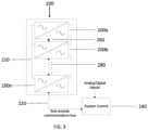
- FIG. 3 is an example of a modular multilevel converter (MMC) according to one or more exemplary embodiments of the present invention.
- MMC modular multilevel converter
- sub-modules 200a, 200b, 200n are directly connected in a hard parallel configuration to common bus 210.
- Sub-module local controllers communicate with system controller 240 via sub-module communication bus 220.
- the sub-modules receive general operating commands from system controller 240 and in turn report their status and pertinent information back to system controller 240.
- each sub-module 200a, 200b, 200n shown here may be a parallel combination of several sub-modules.
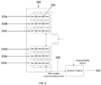
- FIG. 4 is a detailed view of a modular multilevel converter (MMC) according to one or more exemplary embodiments of the present invention.
- MMC modular multilevel converter
- sub-modules 310a, 310b, 310c, 310d, 310e, 310n are directly connected in a hard parallel configuration within MMC 300.
- sub-modules 310a, 310b, 310c, 310d, 310e, 310n are communicatively coupled to system controller 320 via sub-module communication bus 330.
- Each sub-module 310a, 310b, 310c, 310d, 310e, 310n may be a hard parallel combination of several sub-modules as shown in MMC 300.
- sub-module 310a may include sub-modules 310a.1, 310a.2, and 310a.3, which are also connected in a hard parallel configuration, as represented by double arrow 350, and so forth.
- FIG. 5 is an example of a system controller 400 that may be used as the system controller 240 in the modular multilevel converter (MMC) of FIG. 3 according to one or more exemplary embodiments of the present invention.
- MMC modular multilevel converter
- System controller 400 may include one or more voltage sensors 410 which sense the operating conditions of MMC 200, for example.
- the system controller 400 may further include a digital signal processor 420, signal injection module 430, and band stop filter 440 associated with signal injection module 430.
- Digital signal processor 420 serves as a signal interface module which receives electrical signals associated with an operating condition of the one or more voltage sensors 410.
- system controller 400 can communicate desired voltage and modulation commands to the sub-module local controllers based on the operating conditions sensed by the one or more voltage sensors 410, and the sub-module local controllers will then provide status feedback to system controller 400.
- FIG. 6 is an example of a sub-module arrangement that can be implemented within the modular multilevel converter (MMC) of FIG. 3 , performing daisy-chained switching commands according to one or more exemplary embodiments of the present invention.
- MMC modular multilevel converter
- sub-modules 500a, 500b, 500c, 500n are directly connected in a parallel configuration to common bus 510.
- sub-modules 500a, 500b, 500c, 500n are configured to receive a single switching command 520, which is generated by either a sub-module local controller (not shown) or by system controller 240 (also referred to as "controller") and distributed to the power electronic switches of sub-modules 500a, 500b, 500c, 500n in a simple-daisy chain fashion.
- Switching command 520 can either be in a conducting state in which current is allowed to flow through the power electronic switches of sub-modules 500a, 500b, 500c, 500n, or they can be in a blocking state where current is not allowed to flow through the power electronic switches of sub-modules 500a, 500b, 500c, 500n.
- switching command 520 is what determines how sub-modules 500a, 500b, 500c, 500n should turn on/off their power electronic switches.
- FIG. 7 is an example of the generation of synchronization signals between the sub-modules of FIG. 3 according to one or more exemplary embodiments of the present invention.
- a single synchronization signal 530 (530a, 530b), illustrated as a first synchronization signal (1 st ) 530a (in one direction) and a second synchronization signal (2 nd ) 530b (in the opposite direction) for explanation purposes only, herein is provided.
- the synchronization signal 530 known as a cancellation carrier signal, is generated internally from sub-module 500a or from system controller 240, and propagates in a daisy-chain fashion in a first direction (at 530a) to sub-modules 500a, 500b, 500c and 500n, respectively.
- sub-modules 500a, 500b, 500c and 500n each receive the synchronization signal 530 (530a, 530b) simultaneously in two directions.
- FIG. 8 is another example of the generation of synchronization signals between the sub-modules of FIG. 3 according to one or more exemplary embodiments of the present invention.
- synchronization signal 550 is generated from system controller 240 (as depicted in Fig. 3 ) and propagates in a daisy-chain fashion in one direction to sub-modules 500a, 500b, 500c and 500n which are connected via the common bus 510, respectively.
- synchronization signal 560 is also generated from system controller 240 but propagates directly to sub-module 500n. From sub-module 500n, the synchronization signal 560 then propagates in a daisy-chain fashion in the opposite direction of the synchronization signal 550, into sub-modules 500c, 500b and 500a, respectively. As a result, sub-modules 500a, 500b, 500c, 500n each receives both the synchronization signals 550 and 560 simultaneously, one incoming from a first direction and one incoming from a second direction opposite the first direction.
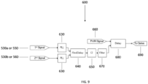
- FIG. 9 is a block diagram illustrating an algorithm being performed by system controller 240 for aligning (e.g., synchronizing) the switching of paralleled sub-modules 200a, 200b and 200n of Fig. 3 with daisy-chained synchronization signal 530 (530a, 530b) as shown in FIG. 7 or with daisy-chained synchronization signals 550, 560 as shown in FIG. 8 .
- aligning e.g., synchronizing the switching of paralleled sub-modules 200a, 200b and 200n of Fig. 3 with daisy-chained synchronization signal 530 (530a, 530b) as shown in FIG. 7 or with daisy-chained synchronization signals 550, 560 as shown in FIG. 8 .
- a synchronization signal 530 (530a, 530b) is generated either internally from sub-module 500a or from system controller 240 (as depicted in Fig. 7 ).
- synchronization signal 530 is illustrated as a first synchronization signal (1 st ) 530a (in one direction) and a second synchronization signal (2 nd ) 530b (in the opposite direction).
- a first synchronization (1 st ) signal 550 and a second synchronization signal (2 nd ) 560 are generated from system controller 240 (as depicted in Fig. 8 ).
- the synchronization signals may be analog voltage/current signals or simple single-bit digital low/high signals.
- each sub-module local controller may optionally be locked onto using phase-locked loop algorithm 630 (PLL) to improve noise cancellation.
- PLL phase-locked loop algorithm 630
- a delay 640 between first synchronization signal 530a or 550 and the second synchronization signal 530b or 560 is then computed, divided by two, and optionally filtered through a filter 670 to generate a desired time delay.
- the executed pulse-width modulation (PWM) gate commands 660 are then delayed via delay step 680 by the computed amount.
- the PWM gate commands dictate how switching devices like those shown in Fig 1 (8a-b/18a-d), for example, operate.
- the local controller of each sub-module 500a-n then phase shifts it's PWM output by the desired time delay which ensures that all sub-modules switch synchronously.
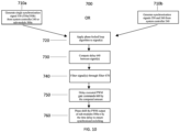
- FIG. 10 is a flow chart illustrating a synchronization method implementing the algorithm of FIG. 9 to be performed by the modular multilevel converter of FIG. 3 according to one or more exemplary embodiments of the present invention.
- single synchronization signal 530 is either generated from system controller 240 or internally from sub-module 500a, as shown in FIG. 7 .
- synchronization signal 530 is illustrated as a first synchronization signal (1 st ) 530a (in one direction) and a second synchronization signal (2 nd ) 530b (in the opposite direction).
- step 710b may be employed, in which synchronization signals 550 and 560 are both generated from system controller 240 in opposite directions, as shown in FIG. 8 .
- a phase-locked loop is applied to synchronization signal 530 (530a, 530b) or synchronization signals 550, 560, to lock on to the phase of synchronization signal 530 (530a, 530b) or synchronization signals 550, 560.
- a delay is computed between synchronization signal 530 flowing in one direction (530a) and synchronization signal 530 flowing in the opposite direction (530b), or between synchronization signals 550, 560.
- Synchronization signals 530a and 530b or 550 and 560 are then filtered through filter 570 at step 740.
- executed PWM gate commands 660 are delayed by the amount computed in step 730, as shown in FIG. 8 .
- the PWM output of sub-modules 500a-n are phase shifted by the time delay determined in step 750 to ensure synchronized switching of the sub-modules.
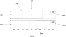
- FIG. 11 is a graph illustrating a comparison between the synchronization signals of the sub-modules of FIG. 7 according to one or more exemplary embodiments of the present invention.
- plots 820, 830 depict the rising edge of the synchronization signals 530 (530a, 530b) of sub-modules 500a and 500c (depicted in FIG. 7 ), respectively.
- the modular multilevel converter and the method performed according to the embodiments of the present invention permit arranging an infinite number of power electronic sub-modules in direct connection with each other, while providing a controller that relies on local sub-module controllers that can communicate and anticipate the delays of the sub-modules, thereby pre-compensating and synchronizing their outputs.
Landscapes
- Engineering & Computer Science (AREA)
- Power Engineering (AREA)
- Inverter Devices (AREA)
- Dc-Dc Converters (AREA)
- Application Of Or Painting With Fluid Materials (AREA)
Abstract
Provided is a modular multilevel converter and a method for synchronizing outputs of sub-modules of the converter. The modular multilevel converter includes sub-modules (200a, 200b, ..., 200n) connected in parallel, and each sub-module generates an output. The modular multilevel converter also includes a controller (240) that is communicatively coupled to the sub-modules (200a, 200b, ..., 200n). The controller (240) controls a flow of one or more synchronizing signals between the plurality of sub-modules (200a, 200b, ..., 200n), such that each sub-module receives the synchronizing signals in opposite directions simultaneously, thereby controlling a synchronization of the outputs generated by the sub-modules (200a, 200b, ..., 200n).
Description
- The technical field relates generally to a modular multilevel converter. In particularly, a modular multilevel converter having a plurality of sub-modules directly connected in a parallel configuration and a method of synchronization of the sub-modules.
- Converters are used for many different applications, for example, for coupling electrical grids and variable-speed drives, photovoltaic and wind power plants, pumped storage power stations, and for energy exchange between two electrical grids.
- There are different types of converters used in the many different applications. For example, conventional modular multilevel converter (MMC) 100 as shown in
Figure 1 , includes sub-modules 40 (40a, 40b, 40c, 40e, 40f) connected to each other in a series configuration. In addition, sub-modules 40 (40a, 40b, 40c, 40e, 40f) are communicatively coupled tosystem control 170 viasub-module communication bus 180. -
Figures 2A and 2B show two types ofsub-modules MMC 100. In these configurations, theinput terminals sub-modules output terminals sensors MMC 100 and a local control unit (e.g.,local controllers 6, 16) which coordinates the operation of the sub-modules. Thesesub-modules electronic switches capacitors inductors 10, 20) and gate drivers which operate powerelectronic switches - In order to increase the power of MMCs, each sub-module may be comprised of several sub-modules arranged in a "soft parallel" configuration. A soft-parallel configuration refers to the sub-modules being connected in parallel with an intermediary inductor between them, forcing equal current sharing amongst the sub-modules. However, a soft-parallel configuration results in increased costs, a higher likelihood of failure between the sub-modules, and takes up space due to the inclusion of the intermediary components.
- To solve the above-mentioned problems, it is desirable to have a system configured to provide a direct connection between the sub-modules while synchronizing the output of multiple sub-modules during operation.
- The embodiments of the present disclosure provide a modular multilevel converter having a plurality of sub-modules directly connected to each other in a hard parallel configuration without any impedance between them and a method of synchronization of the sub-modules.
- A first embodiment provides a power converter, e.g., a modular multilevel converter. The power converter comprises a plurality of sub-modules connected in parallel, each sub-module being configured to generate an output, and a controller communicatively coupled to the plurality of sub-modules and configured to control a flow of one or more synchronizing signals between the plurality of sub-modules. Each sub-module of the plurality of sub-modules receives the one or more synchronizing signals in a first direction and in a second direction opposite the first direction simultaneously, thereby controlling a synchronization of the output generated by each submodule of the plurality of sub-modules.
- The plurality of sub-modules may be directly connected to each other and are further connected in a series configuration.
- The controller may be a computer, microchip, digital signal processor (DSP), or micro-controller, for example.
- A sub-module of the plurality of sub-modules may be further configured to generate the one or more synchronizing signals.
- The controller may be further configured to generate the one or more synchronizing signals. The controller may be further configured to generate a switching command to each sub-module of the plurality of sub-modules, and the switching command may be distributed to each sub-module of the plurality of sub-modules in a daisy-chain operation.
- Upon distributing the switching command, the controller may be further configured to (i) control a flow of a first synchronization signal of the one or more synchronization signals to each sub-module of the plurality of sub-modules in the first direction, and (ii) simultaneously direct the flow of the first synchronization signal of the one or more synchronization signals to each sub-module of the plurality of sub-modules in the second direction opposite the first direction.
- Upon distributing the switching command, the controller may be further configured to: (i) control a flow of a first synchronization signal of the one or more synchronization signals to each sub-module of the plurality of sub-modules in a first direction, and (ii) simultaneously control a flow of a second synchronization signal to each sub-module of the plurality of sub-modules in a second direction opposite the first direction.
- The controller may be further configured to (i) compute a delay in a flow time between the flow of the first synchronization signal in the first direction and the flow of the first synchronization signal in the second direction, and (ii) delay a pulse-width modulation gate command corresponding to each sub-module of the plurality of sub-modules based on the computed delay, wherein each sub-module of the plurality of sub-modules is further configured to receive the first synchronization signal in both the first direction and the second direction simultaneously, thereby synchronizing the output generated by each submodule the plurality of sub-modules.
- The controller may be further configured to (i) compute a delay in a flow time between the flow of the first synchronization signal and the flow of the second synchronization signal, and (ii) delay a pulse-width modulation gate command corresponding to each sub-module of the plurality of sub-modules based on the computed delay, wherein each sub-module of the plurality of sub-modules is further configured to receive the first synchronization signal and the second synchronization signal simultaneously, thereby synchronizing the outputs generated by the plurality of sub-modules.
- A second embodiment provides a method for synchronizing, via a controller, outputs generated by a plurality of sub-modules being connected in parallel, the method comprising: coupling the controller to the plurality of sub-modules, controlling, via the controller, a flow of one or more synchronizing signals between the plurality of sub-modules, and receiving, at each sub-module of the plurality of sub-modules, the one or more synchronizing signals in a first direction and in a second direction opposite the first direction simultaneously, thereby controlling a synchronization of the outputs generated by the plurality of sub-modules.
- The method may further comprise: controlling a flow, via the controller, of a first synchronization signal of the one or more synchronization signals to each sub-module of the plurality of sub-modules in the first direction, and simultaneously directing the flow of the first synchronization signal of the one or more synchronization signals to each sub-module of the plurality of sub-modules in the second direction opposite the first direction.
- The method may further comprise: controlling a flow, via the controller, of a first synchronization signal of the one or more synchronization signals to each sub-module of the plurality of sub-modules in a first direction, and simultaneously controlling a flow, via the controller, of a second synchronization signal to each sub-module of the plurality of sub-modules in a second direction opposite the first direction.
- The method may further comprise: computing, via the controller, a delay in a flow time between the flow of the first synchronization signal in the first direction and the flow of the first synchronization signal in the second direction, delaying, via the controller, a pulse-width modulation gate command corresponding to each sub-module of the plurality of sub-modules based on the computed delay, and shifting, based on the computed delay, a phase of a pulse-width modulation output of each sub-module of the plurality of sub-modules such that each sub-module of the plurality of sub-modules receives the first synchronization signal in both the first direction and the second direction simultaneously, thereby synchronizing the output generated by each submodule of the plurality of sub-modules.
- The method may further comprise: computing, via the controller, a delay in a flow time between the flow of the first synchronization signal and the flow of the second synchronization signal, delaying, via the controller, a pulse-width modulation gate command corresponding to each sub-module of the plurality of sub-modules based on the computed delay, and shifting, based on the computed delay, a phase of a pulse-width modulation output of each sub-module of the plurality of sub-modules such that each sub-module of the plurality of sub-modules receives the first synchronization signal and the second synchronization signal simultaneously, thereby synchronizing the output generated by each submodule of the plurality of sub-modules.
- A third embodiments provides a controller comprising: one or more voltage sensors configured to sense a plurality of operating conditions of a power converter, and a digital signal processor being (i) communicatively coupled to the one or more voltage sensors and (ii) configured to receive a plurality of electrical signals associated with an operating condition of the one or more voltage sensors. The controller is communicatively coupled to a plurality of sub-modules, each sub-module being (i) arranged within the power converter (ii) connected in parallel, and (iii) configured to generate an output. The controller is configured to control a flow of one or more synchronizing signals between the plurality of sub-modules based on the plurality of operating conditions sensed by the one or more voltage sensors. Each sub-module of the plurality of sub-modules receives the one or more synchronizing signals in a first direction and in a second direction opposite the first direction simultaneously, thereby controlling a synchronization of the output generated by each submodule of the plurality of sub-modules.
- The controller may be further configured to generate a switching command to each sub-module of the plurality of sub-modules in a daisy-chain operation. Upon distributing the switching command, the controller may be further configured to (i) control a flow of a first synchronization signal of the one or more synchronization signals to each sub-module of the plurality of sub-modules in the first direction, and (ii) simultaneously direct the flow of the first synchronization signal of the one or more synchronization signals to each sub-module of the plurality of sub-modules in the second direction opposite the first direction.
- The controller may be further configured to generate a switching command to each sub-module of the plurality of sub-modules in a daisy-chain operation. Upon distributing the switching command, the controller may be further configured to: (i) control a flow of a first synchronization signal of the one or more synchronization signals to each sub-module of the plurality of sub-modules in a first direction, and (ii) simultaneously control a flow of a second synchronization signal to each sub-module of the plurality of sub-modules in a second direction opposite the first direction.
- The controller may be further configured to: (i) compute a delay in a flow time between the flow of the first synchronization signal in the first direction and the flow of the first synchronization signal in the second direction, and (ii) delay a pulse-width modulation gate command corresponding to each sub-module of the plurality of sub-modules based on the computed delay, wherein each sub-module of the plurality of sub-modules is further configured to receive the first synchronization signal in both the first direction and the second direction simultaneously, thereby synchronizing the output generated by each submodule of the plurality of sub-modules.
- The controller may be further configured to: (i) compute a delay in a flow time between the flow of the first synchronization signal and the flow of the second synchronization signal, and (ii) delay a pulse-width modulation gate command corresponding to each sub-module of the plurality of sub-modules based on the computed delay. Each sub-module of the plurality of sub-modules may be further configured to receive the first synchronization signal and the second synchronization signal simultaneously, thereby synchronizing the output generated by each submodule of the plurality of sub-modules.
- The foregoing has broadly outlined some of the aspects and features of various embodiments, which should be construed to be merely illustrative of various potential applications of the disclosure. Other beneficial results can be obtained by applying the disclosed information in a different manner or by combining various aspects of the disclosed embodiments. Accordingly, other aspects and a more comprehensive understanding may be obtained by referring to the detailed description of the exemplary embodiments taken in conjunction with the accompanying drawings, in addition to the scope defined by the claims.
-
-
FIG. 1 is an example of a modular multilevel converter (MMC) according to the prior art. -
FIGs. 2A and 2B are examples of sub-modules which are used in modular multilevel converter (MMC) converters according to the prior art. -
FIG. 3 is an example of a modular multilevel converter (MMC) according to one or more exemplary embodiments of the present invention. -
FIG. 4 is a detailed view of a modular multilevel converter (MMC) according to one or more exemplary embodiments of the present invention. -
FIG. 5 is an example of asystem controller 400 that may be used as thesystem controller 240 in the modular multilevel converter (MMC) ofFIG. 3 according to one or more exemplary embodiments of the present invention. -
FIG. 6 is an example of a sub-module arrangement that can be implemented within the modular multilevel converter (MMC) ofFigure 3 performing a daisy-chain switching operation according to one or more exemplary embodiments of the present invention. -
FIG. 7 is an example of the generation of synchronization signals between the sub-modules ofFIG. 3 according to one or more exemplary embodiments of the present invention. -
FIG. 8 is another example of the generation of synchronization signals between the sub-modules ofFIG. 3 according to one or more exemplary embodiments of the present invention. -
FIG. 9 is a block diagram illustrating an algorithm being performed bysystem controller 240 for aligning (e.g., synchronizing) the switching ofparalleled sub-modules Fig. 3 with daisy-chained synchronization signal 530 (530a, 530b) as shown inFIG. 7 or withsynchronization signals FIG. 8 . -
FIG. 10 is a flow chart illustrating the synchronization method implementing the algorithm ofFIG. 9 to be performed by the modular multilevel converter ofFIG. 3 according to one or more exemplary embodiments of the present invention. -
FIG. 11 is a graph illustrating a comparison between the synchronization signals of the sub-modules ofFIG. 7 according to one or more exemplary embodiments of the present invention. - The drawings are only for purposes of illustrating preferred embodiments and are not to be construed as limiting the disclosure. Given the following enabling description of the drawings, the novel aspects of the present disclosure should become evident to a person of ordinary skill in the art. This detailed description uses numerical and letter designations to refer to features in the drawings. Like or similar designations in the drawings and description have been used to refer to like or similar parts of embodiments of the invention.
- As required, detailed embodiments are disclosed herein. It must be understood that the disclosed embodiments are merely exemplary of various and alternative forms. As used herein, the word "exemplary" is used expansively to refer to embodiments that serve as illustrations, specimens, models, or patterns. The figures are not necessarily to scale and some features may be exaggerated or minimized to show details of particular components. In other instances, well-known components, systems, materials, or methods that are known to those having ordinary skill in the art have not been described in detail in order to avoid obscuring the present disclosure. Therefore, specific structural and functional details disclosed herein are not to be interpreted as limiting, but merely as a basis for the claims and as a representative basis for teaching one skilled in the art.
- Furthermore, embodiments may be implemented by hardware, software, firmware, middleware, microcode, hardware description languages, or any combination thereof. When implemented in software, firmware, middleware or microcode, the program code or code segments to perform the necessary tasks may be stored in a machine readable medium. A processor(s) may perform the necessary tasks.
- Embodiments of the present invention provide a modular multilevel converter (MMC) including a system controller and method of operating the MMC permitting hard-paralleling of a plurality of power electronic sub-modules. There are many different control architectures for such converters, but typically there are at least two levels, a system level controller which orchestrates high-level control objectives (power regulation, voltage regulation, etc.) and a local level controller which implements switching functions and may regulate local system parameters (e.g., local capacitor voltages). Typically, the system controller will communicate desired overall voltage or modulation commands to the local controllers, and the local controllers will provide status and measurement feedbacks to the system level controller. The system controller relies upon local sub-module controllers communicating and anticipating the delays of each other, then pre-compensating their outputs, to thereby synchronize their outputs. It should also be noted that while much of the invention is being described herein as applied to MMC type converters, embodiments of the invention are also applicable to any power electronic converter which has multiple paralleled output channels.
-
FIG. 3 is an example of a modular multilevel converter (MMC) according to one or more exemplary embodiments of the present invention. In this configuration, sub-modules 200a, 200b, 200n are directly connected in a hard parallel configuration tocommon bus 210. Sub-module local controllers communicate withsystem controller 240 viasub-module communication bus 220. The sub-modules receive general operating commands fromsystem controller 240 and in turn report their status and pertinent information back tosystem controller 240. It should be noted that each sub-module 200a, 200b, 200n shown here may be a parallel combination of several sub-modules. - Additional details regarding a modular multilevel converter according to the invention will now be described with reference to
FIG. 4 . -
FIG. 4 is a detailed view of a modular multilevel converter (MMC) according to one or more exemplary embodiments of the present invention. In this configuration, sub-modules 310a, 310b, 310c, 310d, 310e, 310n are directly connected in a hard parallel configuration withinMMC 300. In addition, sub-modules 310a, 310b, 310c, 310d, 310e, 310n are communicatively coupled tosystem controller 320 viasub-module communication bus 330. Each sub-module 310a, 310b, 310c, 310d, 310e, 310n may be a hard parallel combination of several sub-modules as shown inMMC 300. For example, sub-module 310a may include sub-modules 310a.1, 310a.2, and 310a.3, which are also connected in a hard parallel configuration, as represented bydouble arrow 350, and so forth. - Additional details regarding the
system controller 240 of modularmultilevel converter 200 ofFIG. 3 will now be described with reference toFIG. 5 . -
FIG. 5 is an example of asystem controller 400 that may be used as thesystem controller 240 in the modular multilevel converter (MMC) ofFIG. 3 according to one or more exemplary embodiments of the present invention. -
System controller 400 may include one ormore voltage sensors 410 which sense the operating conditions ofMMC 200, for example. In certain embodiments, thesystem controller 400 may further include adigital signal processor 420,signal injection module 430, andband stop filter 440 associated withsignal injection module 430.Digital signal processor 420 serves as a signal interface module which receives electrical signals associated with an operating condition of the one ormore voltage sensors 410. In this configuration,system controller 400 can communicate desired voltage and modulation commands to the sub-module local controllers based on the operating conditions sensed by the one ormore voltage sensors 410, and the sub-module local controllers will then provide status feedback tosystem controller 400. -
FIG. 6 is an example of a sub-module arrangement that can be implemented within the modular multilevel converter (MMC) ofFIG. 3 , performing daisy-chained switching commands according to one or more exemplary embodiments of the present invention. - As shown in
FIG. 6 , sub-modules 500a, 500b, 500c, 500n are directly connected in a parallel configuration tocommon bus 510. In addition, sub-modules 500a, 500b, 500c, 500n are configured to receive asingle switching command 520, which is generated by either a sub-module local controller (not shown) or by system controller 240 (also referred to as "controller") and distributed to the power electronic switches of sub-modules 500a, 500b, 500c, 500n in a simple-daisy chain fashion.Switching command 520 can either be in a conducting state in which current is allowed to flow through the power electronic switches of sub-modules 500a, 500b, 500c, 500n, or they can be in a blocking state where current is not allowed to flow through the power electronic switches of sub-modules 500a, 500b, 500c, 500n. Thus, switchingcommand 520 is what determines how sub-modules 500a, 500b, 500c, 500n should turn on/off their power electronic switches. -
FIG. 7 is an example of the generation of synchronization signals between the sub-modules ofFIG. 3 according to one or more exemplary embodiments of the present invention. - According to
FIG. 7 , a single synchronization signal 530 (530a, 530b), illustrated as a first synchronization signal (1st) 530a (in one direction) and a second synchronization signal (2nd) 530b (in the opposite direction) for explanation purposes only, herein is provided. According to an embodiment, thesynchronization signal 530, known as a cancellation carrier signal, is generated internally from sub-module 500a or fromsystem controller 240, and propagates in a daisy-chain fashion in a first direction (at 530a) to sub-modules 500a, 500b, 500c and 500n, respectively. This is followed by a propagation of thesynchronization signal 530 in a daisy-chain fashion in a second direction opposite the first direction (at 530b) tosub-modules -
FIG. 8 is another example of the generation of synchronization signals between the sub-modules ofFIG. 3 according to one or more exemplary embodiments of the present invention. - As shown in
FIG. 8 , twoseparate synchronization signals synchronization signal 550 is generated from system controller 240 (as depicted inFig. 3 ) and propagates in a daisy-chain fashion in one direction to sub-modules 500a, 500b, 500c and 500n which are connected via thecommon bus 510, respectively. - Further,
synchronization signal 560 is also generated fromsystem controller 240 but propagates directly to sub-module 500n. From sub-module 500n, thesynchronization signal 560 then propagates in a daisy-chain fashion in the opposite direction of thesynchronization signal 550, intosub-modules -
FIG. 9 is a block diagram illustrating an algorithm being performed bysystem controller 240 for aligning (e.g., synchronizing) the switching of paralleled sub-modules 200a, 200b and 200n ofFig. 3 with daisy-chained synchronization signal 530 (530a, 530b) as shown inFIG. 7 or with daisy-chained synchronization signals 550, 560 as shown inFIG. 8 . - According to
algorithm 600, a synchronization signal 530 (530a, 530b) is generated either internally from sub-module 500a or from system controller 240 (as depicted inFig. 7 ). As noted earlier,synchronization signal 530 is illustrated as a first synchronization signal (1st) 530a (in one direction) and a second synchronization signal (2nd) 530b (in the opposite direction). Alternatively, a first synchronization (1st) signal 550 and a second synchronization signal (2nd) 560 are generated from system controller 240 (as depicted inFig. 8 ). The synchronization signals may be analog voltage/current signals or simple single-bit digital low/high signals. These signals are propagated and read by each sub-module local controller assignals 1 and 2. These signals may optionally be locked onto using phase-locked loop algorithm 630 (PLL) to improve noise cancellation. Adelay 640 betweenfirst synchronization signal second synchronization signal filter 670 to generate a desired time delay. The executed pulse-width modulation (PWM) gate commands 660 are then delayed viadelay step 680 by the computed amount. The PWM gate commands dictate how switching devices like those shown inFig 1 (8a-b/18a-d), for example, operate. The local controller of each sub-module 500a-n then phase shifts it's PWM output by the desired time delay which ensures that all sub-modules switch synchronously. -
FIG. 10 is a flow chart illustrating a synchronization method implementing the algorithm ofFIG. 9 to be performed by the modular multilevel converter ofFIG. 3 according to one or more exemplary embodiments of the present invention. - At
step 710a,single synchronization signal 530 is either generated fromsystem controller 240 or internally from sub-module 500a, as shown inFIG. 7 . As noted earlier,synchronization signal 530 is illustrated as a first synchronization signal (1st) 530a (in one direction) and a second synchronization signal (2nd) 530b (in the opposite direction). Alternatively,step 710b may be employed, in which synchronization signals 550 and 560 are both generated fromsystem controller 240 in opposite directions, as shown inFIG. 8 . Atstep 720, a phase-locked loop is applied to synchronization signal 530 (530a, 530b) orsynchronization signals synchronization signals step 730, a delay is computed betweensynchronization signal 530 flowing in one direction (530a) andsynchronization signal 530 flowing in the opposite direction (530b), or between synchronization signals 550, 560.Synchronization signals step 740. Atstep 750, executed PWM gate commands 660 are delayed by the amount computed instep 730, as shown inFIG. 8 . Finally, atstep 760, the PWM output of sub-modules 500a-n are phase shifted by the time delay determined instep 750 to ensure synchronized switching of the sub-modules. -
FIG. 11 is a graph illustrating a comparison between the synchronization signals of the sub-modules ofFIG. 7 according to one or more exemplary embodiments of the present invention. - According to
FIG. 11 ,plots FIG. 7 ), respectively.Single synchronization signal 530, including 530a and 530b, is generated, whereinsynchronization signal 530a arrives first to sub-module 500a at t=1, and then to sub-module 500c at t=1.03. Then, thesynchronization signal 530b returns and arrives first at sub-module 500c at t=1.06 and finally arrives at sub-module 500a last at t=1.09. In the event that both sub-modules were to begin a switching event at the average of the twosynchronization signals - The modular multilevel converter and the method performed according to the embodiments of the present invention permit arranging an infinite number of power electronic sub-modules in direct connection with each other, while providing a controller that relies on local sub-module controllers that can communicate and anticipate the delays of the sub-modules, thereby pre-compensating and synchronizing their outputs.
- This written description uses examples to disclose the invention, including the best mode, and also to enable any person skilled in the art to practice the invention, including making and using any devices or systems and performing any incorporated methods.
- The patentable scope of the invention is defined by the claims, and may include other examples that occur to those skilled in the art. Such other examples are intended to be within the scope of the claims if they have structural elements that do not differ from the literal language of the claims, or if they include equivalent structural elements with insubstantial differences from the literal languages of the claims.
Claims (15)
- A power converter (300) comprising:a plurality of sub-modules (200a, 200b, ..., 200n; 310a, 310b, ..., 310n; 500a, 500b, ..., 500n) connected in parallel, each sub-module (200a, 200b, ..., 200n; 310a, 310b, ..., 310n; 500a, 500b, ..., 500n) being configured to generate an output; anda controller (240; 320; 400) communicatively coupled to the plurality of sub-modules (200a, 200b, ..., 200n; 310a, 310b, ..., 310n; 500a, 500b, ..., 500n) and configured to control a flow of one or more synchronizing signals between the plurality of sub-modules (200a, 200b, ..., 200n; 310a, 310b, ..., 310n; 500a, 500b, ..., 500n), wherein each sub-module of the plurality of sub-modules (200a, 200b, ..., 200n; 310a, 310b, ..., 310n; 500a, 500b, ..., 500n) receives the one or more synchronizing signals in a first direction and in a second direction opposite the first direction simultaneously, thereby controlling a synchronization of the output generated by each submodule of the plurality of sub-modules (200a, 200b, ..., 200n; 310a, 310b, ..., 310n; 500a, 500b, ..., 500n).
- A power converter (300) according to claim 1, wherein the plurality of sub-modules (200a, 200b, ..., 200n; 310a, 310b, ..., 310n; 500a, 500b, ..., 500n) are directly connected to each other and are further connected in a series configuration.
- A power converter (300) according to claim 1 or claim 2, wherein the controller (240; 320; 400) is a computer, microchip, digital signal processor (DSP), or micro-controller.
- A power converter (300) according to any preceding claim, wherein a sub-module of the plurality of sub-modules (200a, 200b, ..., 200n; 3 10a, 3 10b, ..., 3 10n; 500a, 500b, ..., 500n) is further configured to generate the one or more synchronizing signals.
- A power converter (300) according to any of claims 1 to 3, wherein the controller (240; 320; 400) is further configured to generate the one or more synchronizing signals.
- A power converter (300) according to claim 5, wherein the controller (240; 320; 400) is further configured to generate a switching command to each sub-module of the plurality of sub-modules (200a, 200b, ..., 200n; 310a, 310b, ..., 310n; 500a, 500b, ..., 500n), and wherein the switching command is distributed to each sub-module of the plurality of sub-modules in a daisy-chain operation.
- A power converter (300) according to claim 6, wherein, upon distributing the switching command, the controller (240; 320; 400) is further configured to (i) control a flow of a first synchronization signal of the one or more synchronization signals to each sub-module of the plurality of sub-modules (200a, 200b, ..., 200n; 310a, 310b, ..., 310n; 500a, 500b, ..., 500n) in the first direction; and (ii) simultaneously direct the flow of the first synchronization signal of the one or more synchronization signals to each sub-module of the plurality of sub-modules (200a, 200b, ..., 200n; 3 10a, 3 10b, ..., 3 10n; 500a, 500b, ..., 500n) in the second direction opposite the first direction.
- A power converter (300) according to claim 6, wherein upon distributing the switching command, the controller (240; 320; 400) is further configured to: (i) control a flow of a first synchronization signal of the one or more synchronization signals to each sub-module of the plurality of sub-modules (200a, 200b, ..., 200n; 310a, 310b, ..., 310n; 500a, 500b, ..., 500n) in a first direction, and (ii) simultaneously control a flow of a second synchronization signal to each sub-module of the plurality of sub-modules (200a, 200b, ..., 200n; 310a, 310b, ..., 310n; 500a, 500b, ..., 500n) in a second direction opposite the first direction.
- A power converter (300) according to claim 7, wherein the controller (240; 320; 400) is further configured to (i) compute a delay in a flow time between the flow of the first synchronization signal in the first direction and the flow of the first synchronization signal in the second direction, and (ii) delay a pulse-width modulation gate command corresponding to each sub-module of the plurality of sub-modules (200a, 200b, ..., 200n; 310a, 310b, ..., 310n; 500a, 500b, ..., 500n) based on the computed delay, wherein each sub-module of the plurality of sub-modules (200a, 200b, ..., 200n; 310a, 310b, ..., 310n; 500a, 500b, ..., 500n) is further configured to receive the first synchronization signal in both the first direction and the second direction simultaneously, thereby synchronizing the output generated by each submodule the plurality of sub-modules (200a, 200b, ..., 200n; 310a, 310b, ..., 310n; 500a, 500b, ..., 500n).
- A power converter (300) according to claim 8, wherein the controller (240; 320; 400) is further configured to (i) compute a delay in a flow time between the flow of the first synchronization signal and the flow of the second synchronization signal, and (ii) delay a pulse-width modulation gate command corresponding to each sub-module of the plurality of sub-modules (200a, 200b, ..., 200n; 310a, 310b, ..., 310n; 500a, 500b, ..., 500n) based on the computed delay, wherein each sub-module of the plurality of sub-modules (200a, 200b, ..., 200n; 310a, 310b, ..., 310n; 500a, 500b, ..., 500n) is further configured to receive the first synchronization signal and the second synchronization signal simultaneously, thereby synchronizing the outputs generated by the plurality of sub-modules (200a, 200b, ..., 200n; 310a, 310b, ..., 310n; 500a, 500b, ..., 500n).
- A method for synchronizing, via a controller (240; 320; 400), outputs generated by a plurality of sub-modules (200a, 200b, ..., 200n; 310a, 310b, ..., 310n; 500a, 500b, ..., 500n) being connected in parallel, the method comprising:coupling the controller (240; 320; 400) to the plurality of sub-modules (200a, 200b, ..., 200n; 310a, 310b, ..., 310n; 500a, 500b, ..., 500n);controlling, via the controller (240; 320; 400), a flow of one or more synchronizing signals between the plurality of sub-modules (200a, 200b, ..., 200n; 310a, 310b, ..., 310n; 500a, 500b, ..., 500n); andreceiving, at each sub-module of the plurality of sub-modules (200a, 200b, ..., 200n; 310a, 310b, ..., 310n; 500a, 500b, ..., 500n), the one or more synchronizing signals in a first direction and in a second direction opposite the first direction simultaneously, thereby controlling a synchronization of the outputs generated by the plurality of sub-modules (200a, 200b, ..., 200n; 310a, 310b, ..., 310n; 500a, 500b, ..., 500n).
- A method according to claim 11, further comprising:controlling a flow, via the controller (240; 320; 400), of a first synchronization signal of the one or more synchronization signals to each sub-module of the plurality of sub-modules (200a, 200b, ..., 200n; 310a, 310b, ..., 310n; 500a, 500b, ..., 500n) in the first direction; andsimultaneously directing the flow of the first synchronization signal of the one or more synchronization signals to each sub-module of the plurality of sub-modules (200a, 200b, ..., 200n; 310a, 310b, ..., 310n; 500a, 500b, ..., 500n) in the second direction opposite the first direction.
- A method according to claim 11, further comprising:controlling a flow, via the controller (240; 320; 400), of a first synchronization signal of the one or more synchronization signals to each sub-module of the plurality of sub-modules (200a, 200b, ..., 200n; 310a, 310b, ..., 310n; 500a, 500b, ..., 500n) in a first direction; andsimultaneously controlling a flow, via the controller (240; 320; 400), of a second synchronization signal to each sub-module of the plurality of sub-modules (200a, 200b, ..., 200n; 310a, 310b, ..., 310n; 500a, 500b, ..., 500n) in a second direction opposite the first direction.
- A method according to claim 12, further comprising:computing, via the controller (240; 320; 400), a delay in a flow time between the flow of the first synchronization signal in the first direction and the flow of the first synchronization signal in the second direction; anddelaying, via the controller (240; 320; 400), a pulse-width modulation gate command corresponding to each sub-module of the plurality of sub-modules (200a, 200b, ..., 200n; 310a, 310b, ..., 310n; 500a, 500b, ..., 500n) based on the computed delay;shifting, based on the computed delay, a phase of a pulse-width modulation output of each sub-module of the plurality of sub-modules (200a, 200b, ..., 200n; 310a, 310b, ..., 310n; 500a, 500b, ..., 500n) such that each sub-module of the plurality of sub-modules (200a, 200b, ..., 200n; 310a, 310b, ..., 310n; 500a, 500b, ..., 500n) receives the first synchronization signal in both the first direction and the second direction simultaneously, thereby synchronizing the output generated by each submodule of the plurality of sub-modules (200a, 200b, ..., 200n; 310a, 310b, ..., 310n; 500a, 500b, ..., 500n).
- A method according to claim 13, further comprising:computing, via the controller (240; 320; 400), a delay in a flow time between the flow of the first synchronization signal and the flow of the second synchronization signal;delaying, via the controller (240; 320; 400), a pulse-width modulation gate command corresponding to each sub-module of the plurality of sub-modules (200a, 200b, ..., 200n; 310a, 310b, ..., 310n; 500a, 500b, ..., 500n) based on the computed delay; andshifting, based on the computed delay, a phase of a pulse-width modulation output of each sub-module of the plurality of sub-modules (200a, 200b, ..., 200n; 310a, 310b, ..., 310n; 500a, 500b, ..., 500n) such that each sub-module of the plurality of sub-modules (200a, 200b, ..., 200n; 3 10a, 3 10b, ..., 3 10n; 500a, 500b, ..., 500n) receives the first synchronization signal and the second synchronization signal simultaneously, thereby synchronizing the output generated by each submodule of the plurality of sub-modules (200a, 200b, ..., 200n; 310a, 310b, ..., 310n; 500a, 500b, ..., 500n).
Applications Claiming Priority (1)
| Application Number | Priority Date | Filing Date | Title |
|---|---|---|---|
| US17/714,992 US12081140B2 (en) | 2022-04-06 | 2022-04-06 | Switching synchronization for modular multilevel converters |
Publications (1)
| Publication Number | Publication Date |
|---|---|
| EP4258527A1 true EP4258527A1 (en) | 2023-10-11 |
Family
ID=85795356
Family Applications (1)
| Application Number | Title | Priority Date | Filing Date |
|---|---|---|---|
| EP23165808.9A Withdrawn EP4258527A1 (en) | 2022-04-06 | 2023-03-31 | Switching synchronization for modular multilevel converters |
Country Status (4)
| Country | Link |
|---|---|
| US (1) | US12081140B2 (en) |
| EP (1) | EP4258527A1 (en) |
| KR (1) | KR20230143924A (en) |
| AU (1) | AU2023201810A1 (en) |
Families Citing this family (5)
| Publication number | Priority date | Publication date | Assignee | Title |
|---|---|---|---|---|
| US12542440B2 (en) | 2023-04-12 | 2026-02-03 | DG Matrix, Inc. | Resilient on-site microgrid system |
| US12620886B2 (en) | 2023-04-12 | 2026-05-05 | DG Matrix, Inc. | Multiport transformer enabled modular multiport power conversion system |
| US12489359B2 (en) | 2023-12-06 | 2025-12-02 | DG Matrix, Inc. | Power supply and demand synchronization system and method for modular multi-port system |
| US12640568B2 (en) | 2023-12-06 | 2026-05-26 | DG Matrix, Inc. | Power supply and demand synchronization system and method for modular multi-port system |
| EP4742475A1 (en) | 2024-11-08 | 2026-05-13 | CE+T Power Luxembourg SA | Universal sustainable energy conversion system |
Citations (2)
| Publication number | Priority date | Publication date | Assignee | Title |
|---|---|---|---|---|
| DE19917354A1 (en) * | 1999-04-16 | 2000-10-19 | Siemens Ag | Synchronisation method for communication systems |
| EP3059848A1 (en) * | 2015-02-20 | 2016-08-24 | GE Energy Power Conversion Technology Ltd | Systems and methods to optimize active current sharing of parallel power converters |
Family Cites Families (11)
| Publication number | Priority date | Publication date | Assignee | Title |
|---|---|---|---|---|
| CN1228908C (en) | 2001-12-31 | 2005-11-23 | 艾默生网络能源有限公司 | Switch synchronization method of parallel converter system. |
| US6965219B2 (en) | 2002-06-28 | 2005-11-15 | Microsemi Corporation | Method and apparatus for auto-interleaving synchronization in a multiphase switching power converter |
| AT504120B1 (en) * | 2006-09-28 | 2008-03-15 | Fronius Int Gmbh | INVERTER SYSTEM, INVERTER AND METHOD FOR OPERATING INVERTERS OF AN INVERTER SYSTEM |
| US8120935B2 (en) * | 2011-03-29 | 2012-02-21 | American Superconductor Corporation | Power converter with dual ring network control |
| EP2946466B1 (en) | 2013-08-30 | 2016-07-20 | ABB Technology AG | Parallel modular multilevel converters |
| WO2015041638A1 (en) * | 2013-09-18 | 2015-03-26 | Siemens Industry, Inc. | Fiber optic ring for bypass system in multi-cell power supply |
| CN103904876B (en) | 2014-04-22 | 2017-01-04 | 华北电力大学 | The modularization multi-level converter possessing simultaneous interconnecting function smooths startup method |
| JP6546293B2 (en) * | 2016-01-15 | 2019-07-17 | 東芝三菱電機産業システム株式会社 | Control system |
| ES2794423T3 (en) * | 2016-01-19 | 2020-11-18 | Siemens Ag | Modular multilevel converter |
| US9866113B1 (en) | 2016-12-15 | 2018-01-09 | Texas Instruments Incorporated | Multilevel buck converter with a flying capacitor and charge pump |
| CN107834867B (en) | 2017-10-24 | 2018-11-13 | 南京理工大学 | A kind of accurate two level PWM control methods of module multi-level converter based on SIC devices |
-
2022
- 2022-04-06 US US17/714,992 patent/US12081140B2/en active Active
-
2023
- 2023-02-14 KR KR1020230019464A patent/KR20230143924A/en active Pending
- 2023-03-23 AU AU2023201810A patent/AU2023201810A1/en active Pending
- 2023-03-31 EP EP23165808.9A patent/EP4258527A1/en not_active Withdrawn
Patent Citations (2)
| Publication number | Priority date | Publication date | Assignee | Title |
|---|---|---|---|---|
| DE19917354A1 (en) * | 1999-04-16 | 2000-10-19 | Siemens Ag | Synchronisation method for communication systems |
| EP3059848A1 (en) * | 2015-02-20 | 2016-08-24 | GE Energy Power Conversion Technology Ltd | Systems and methods to optimize active current sharing of parallel power converters |
Non-Patent Citations (1)
| Title |
|---|
| AZIDEHAK ALI ET AL: "Control and synchronization of distributed controllers in modular converters", IECON 2014 - 40TH ANNUAL CONFERENCE OF THE IEEE INDUSTRIAL ELECTRONICS SOCIETY, IEEE, 29 October 2014 (2014-10-29), pages 3644 - 3650, XP032739804, DOI: 10.1109/IECON.2014.7049041 * |
Also Published As
| Publication number | Publication date |
|---|---|
| KR20230143924A (en) | 2023-10-13 |
| US20230327574A1 (en) | 2023-10-12 |
| AU2023201810A1 (en) | 2023-10-26 |
| US12081140B2 (en) | 2024-09-03 |
Similar Documents
| Publication | Publication Date | Title |
|---|---|---|
| US12081140B2 (en) | Switching synchronization for modular multilevel converters | |
| KR101711947B1 (en) | Modular multilevel converter | |
| CN209299159U (en) | Modular multilevel converter | |
| Hu et al. | DC‐link voltage control strategy for reducing capacitance and total harmonic distortion in single‐phase grid‐connected photovoltaic inverters | |
| US10326357B1 (en) | Adaptive power converter topologies supporting active power factor correction (PFC) | |
| US7138788B2 (en) | Switch controller for a power control system and method therefor | |
| EP2903144B1 (en) | Power conversion system and method of operating the same | |
| CN101795068A (en) | Switch type regulator and control method thereof | |
| US20120176817A1 (en) | Dc-dc converter | |
| US20240235400A9 (en) | System and Method for Multi-Phase Power Conversion and Control | |
| EP3709492B1 (en) | Distributed control of a multiphase power converter | |
| KR102475105B1 (en) | Solar photovotaics system having micro converters | |
| KR100738571B1 (en) | H-Bridge Multilevel Inverter System using CAN Communication Interrupt | |
| CN111464002A (en) | Voltage regulating device | |
| JP7666124B2 (en) | Power Conversion Equipment | |
| US9438098B2 (en) | Apparatus and method for controlling module switching of power converting system | |
| Cvetanovic et al. | Nonlinearities of multisampled phase-shifted PWM in unbalanced multicell converters | |
| WO2016075519A1 (en) | Power conversion device | |
| CN104811070B (en) | Power conversion system and method of operation thereof | |
| US11563379B2 (en) | Phase current balancing for multiphase coupled inductor converter | |
| KR20170111495A (en) | Control device with duplex system | |
| JP2007151390A (en) | Control circuit for two-stage voltage converter | |
| Teja et al. | Single phase 9 level symmetrical cascaded H-bridge inverter for different PWM techniques | |
| JPH06350415A (en) | Module clock signal genarating circuit and electronics system | |
| KR20230128814A (en) | Four-Level Active Neutral-Point-Clamped Inverters for Fault-Tolerant Operation |
Legal Events
| Date | Code | Title | Description |
|---|---|---|---|
| PUAI | Public reference made under article 153(3) epc to a published international application that has entered the european phase |
Free format text: ORIGINAL CODE: 0009012 |
|
| STAA | Information on the status of an ep patent application or granted ep patent |
Free format text: STATUS: THE APPLICATION HAS BEEN PUBLISHED |
|
| AK | Designated contracting states |
Kind code of ref document: A1 Designated state(s): AL AT BE BG CH CY CZ DE DK EE ES FI FR GB GR HR HU IE IS IT LI LT LU LV MC ME MK MT NL NO PL PT RO RS SE SI SK SM TR |
|
| RAP1 | Party data changed (applicant data changed or rights of an application transferred) |
Owner name: GE ENERGY POWER CONVERSION TECHNOLOGY LTD |
|
| STAA | Information on the status of an ep patent application or granted ep patent |
Free format text: STATUS: THE APPLICATION IS DEEMED TO BE WITHDRAWN |
|
| 18D | Application deemed to be withdrawn |
Effective date: 20240412 |