EP4258491A1 - Vibration resistant connector system with mating assistance feature - Google Patents
Vibration resistant connector system with mating assistance feature Download PDFInfo
- Publication number
- EP4258491A1 EP4258491A1 EP23166285.9A EP23166285A EP4258491A1 EP 4258491 A1 EP4258491 A1 EP 4258491A1 EP 23166285 A EP23166285 A EP 23166285A EP 4258491 A1 EP4258491 A1 EP 4258491A1
- Authority
- EP
- European Patent Office
- Prior art keywords
- mounting
- connector
- stud
- nut
- header
- Prior art date
- Legal status (The legal status is an assumption and is not a legal conclusion. Google has not performed a legal analysis and makes no representation as to the accuracy of the status listed.)
- Pending
Links
Images




Classifications
-
- H—ELECTRICITY
- H01—ELECTRIC ELEMENTS
- H01R—ELECTRICALLY-CONDUCTIVE CONNECTIONS; STRUCTURAL ASSOCIATIONS OF A PLURALITY OF MUTUALLY-INSULATED ELECTRICAL CONNECTING ELEMENTS; COUPLING DEVICES; CURRENT COLLECTORS
- H01R13/00—Details of coupling devices of the kinds covered by groups H01R12/70 or H01R24/00 - H01R33/00
- H01R13/62—Means for facilitating engagement or disengagement of coupling parts or for holding them in engagement
- H01R13/629—Additional means for facilitating engagement or disengagement of coupling parts, e.g. aligning or guiding means, levers, gas pressure electrical locking indicators, manufacturing tolerances
- H01R13/62933—Comprising exclusively pivoting lever
-
- H—ELECTRICITY
- H01—ELECTRIC ELEMENTS
- H01R—ELECTRICALLY-CONDUCTIVE CONNECTIONS; STRUCTURAL ASSOCIATIONS OF A PLURALITY OF MUTUALLY-INSULATED ELECTRICAL CONNECTING ELEMENTS; COUPLING DEVICES; CURRENT COLLECTORS
- H01R13/00—Details of coupling devices of the kinds covered by groups H01R12/70 or H01R24/00 - H01R33/00
- H01R13/46—Bases; Cases
- H01R13/533—Bases, cases made for use in extreme conditions, e.g. high temperature, radiation, vibration, corrosive environment, pressure
-
- H—ELECTRICITY
- H01—ELECTRIC ELEMENTS
- H01R—ELECTRICALLY-CONDUCTIVE CONNECTIONS; STRUCTURAL ASSOCIATIONS OF A PLURALITY OF MUTUALLY-INSULATED ELECTRICAL CONNECTING ELEMENTS; COUPLING DEVICES; CURRENT COLLECTORS
- H01R13/00—Details of coupling devices of the kinds covered by groups H01R12/70 or H01R24/00 - H01R33/00
- H01R13/46—Bases; Cases
- H01R13/502—Bases; Cases composed of different pieces
- H01R13/512—Bases; Cases composed of different pieces assembled by screw or screws
-
- H—ELECTRICITY
- H01—ELECTRIC ELEMENTS
- H01R—ELECTRICALLY-CONDUCTIVE CONNECTIONS; STRUCTURAL ASSOCIATIONS OF A PLURALITY OF MUTUALLY-INSULATED ELECTRICAL CONNECTING ELEMENTS; COUPLING DEVICES; CURRENT COLLECTORS
- H01R13/00—Details of coupling devices of the kinds covered by groups H01R12/70 or H01R24/00 - H01R33/00
- H01R13/62—Means for facilitating engagement or disengagement of coupling parts or for holding them in engagement
- H01R13/621—Bolt, set screw or screw clamp
- H01R13/6215—Bolt, set screw or screw clamp using one or more bolts
-
- H—ELECTRICITY
- H01—ELECTRIC ELEMENTS
- H01R—ELECTRICALLY-CONDUCTIVE CONNECTIONS; STRUCTURAL ASSOCIATIONS OF A PLURALITY OF MUTUALLY-INSULATED ELECTRICAL CONNECTING ELEMENTS; COUPLING DEVICES; CURRENT COLLECTORS
- H01R13/00—Details of coupling devices of the kinds covered by groups H01R12/70 or H01R24/00 - H01R33/00
- H01R13/62—Means for facilitating engagement or disengagement of coupling parts or for holding them in engagement
- H01R13/629—Additional means for facilitating engagement or disengagement of coupling parts, e.g. aligning or guiding means, levers, gas pressure electrical locking indicators, manufacturing tolerances
- H01R13/62933—Comprising exclusively pivoting lever
- H01R13/62938—Pivoting lever comprising own camming means
-
- H—ELECTRICITY
- H01—ELECTRIC ELEMENTS
- H01R—ELECTRICALLY-CONDUCTIVE CONNECTIONS; STRUCTURAL ASSOCIATIONS OF A PLURALITY OF MUTUALLY-INSULATED ELECTRICAL CONNECTING ELEMENTS; COUPLING DEVICES; CURRENT COLLECTORS
- H01R43/00—Apparatus or processes specially adapted for manufacturing, assembling, maintaining, or repairing of line connectors or current collectors or for joining electric conductors
- H01R43/20—Apparatus or processes specially adapted for manufacturing, assembling, maintaining, or repairing of line connectors or current collectors or for joining electric conductors for assembling or disassembling contact members with insulating base, case or sleeve
-
- H—ELECTRICITY
- H01—ELECTRIC ELEMENTS
- H01R—ELECTRICALLY-CONDUCTIVE CONNECTIONS; STRUCTURAL ASSOCIATIONS OF A PLURALITY OF MUTUALLY-INSULATED ELECTRICAL CONNECTING ELEMENTS; COUPLING DEVICES; CURRENT COLLECTORS
- H01R2201/00—Connectors or connections adapted for particular applications
- H01R2201/26—Connectors or connections adapted for particular applications for vehicles
Definitions
- This disclosure is directed to a vibration resistant connector system with a mating assistance feature, e.g., automotive electrical connector assemblies.
- lever-based connector mating assist systems provide a means to meet connector mating ergonomic requirements without the need for special tools or assembly fixtures.
- these conventional lever-based connector mating assist systems are not well suited for applications in which higher levels of vibration are experienced by the connector system due to relative motion between the male and female connectors of the connector system. Therefore, a connector mating system that does not require special tools or fixtures and that is suited for use in higher vibration applications remains desired.
- a connector assembly includes a connector header configured to be attached to a mounting substrate by a first mounting stud extending through a first aperture defined by the connector header, a connector configured to mate and unmate with the connector header and having a mating assist lever configured to attach and detach the connector to and from the connector header, and a mounting tab defined by the connector and configured to attach the connector to the first mounting stud extending through a second aperture defined by the mounting tab.
- the mounting tab is integrally formed with the connector.
- the first mounting stud is threaded.
- the connector header is secured to the first mounting stud by a first threaded nut and the mounting tab is secured to the first nut by a second threaded nut.
- the first nut is integrally formed with the first stud.
- the mounting tab is a first mounting tab.
- the connector header is configured to be attached to the mounting substrate by a second mounting stud that extends through a third aperture defined by the connector header.
- the mating assist lever defines a second mounting tab that is configured to attach the mating assist lever to the second mounting stud which extends through a fourth aperture defined by the second mounting tab.
- the second mounting stud is threaded.
- the connector header is secured to the second mounting stud by a third threaded nut and the second mounting tab is secured to the second mounting stud by a fourth threaded nut.
- the third nut is integrally formed with the second stud.
- the first mounting stud is arranged diagonally with the second mounting stud.
- the mounting tab is integrally formed with the mating assist lever.
- a method of assembling an electrical connector includes the steps of: inserting a first mounting stud extending from a mounting substrate through a first aperture defined by a connector header, placing a first nut on the first mounting stud and securing the connector header to the mounting substrate, inserting the first mounting stud through a second aperture of a mounting tab defined by a connector configured to mate and unmate with the connector header which has a mating assist lever configured to attach and detach the connector to and from the connector header, activating the mating assist lever to attach the connector to the connector header, and placing a second nut on the first mounting stud and securing the mounting tab to the first nut.
- the mounting tab is integrally formed with the connector.
- the first mounting stud is threaded.
- the first nut is integrally formed with the first stud.
- the mounting tab is a first mounting tab.
- the method includes the additional steps of: inserting a second mounting stud extending from the mounting substrate through a third aperture defined by a connector header, placing a third nut on the second mounting stud and further securing the connector header to the mounting substrate, inserting the second mounting stud through a fourth aperture of a second mounting tab defined by the mating assist lever, and placing a fourth nut on the second mounting stud and securing the second mounting tab to the third nut.
- the second mounting stud is threaded.
- the third nut is integrally formed with the first stud.
- the first mounting stud is arranged diagonally with the second mounting stud.
- a method of assembling an electrical connector includes the steps of: inserting a first mounting stud extending from a mounting substrate through a first aperture defined by a connector header, placing a first nut on the first mounting stud and securing the connector header to the mounting substrate, inserting the first mounting stud through a second aperture of a mounting tab defined by a mating assist lever configured to attach and detach a connector to and from the connector header, activating the mating assist lever to attach the connector to the connector header, and placing a second nut on the first mounting stud and securing the mounting tab to the first nut.
- the mounting tab is integrally formed with the mating assist lever.
- the first mounting stud is threaded, and the first nut is integrally formed with the mounting stud.
- connection assist lever 12 such as the example shown in FIG. 1
- connection assist lever 12 provides ease of mating without the need for additional tools.
- Mechanical fastening of the electrical connector 10 to a mounting substrate 14 is provided by the interface connection of the assist lever 12 of the electrical connector 10 to a connector header 18 and the connection of the connector header 18 to the mounting substrate 14.
- the type of electrical connector 10 shown in FIG. 1 may be suitable for applications that experience lower levels of vibration. Since there are two separate connections between the mounting substrate 14 and the electrical connector 10, i.e., the connection between the mounting substrate 14 and the connector header 18; and connection between the connector header 18 and the electrical connector 10, there are also two points at which vibration may enter the connection system.
- FIGs. 2 through 8B The non-limiting example of an electrical connector assembly 100 with a lever-based connector mating assist system that is shown in FIGs. 2 through 8B is designed to resist vibration that may enter the connection system by mechanically fixing an electrical connector 110 to the mounting substrate 114 after the electrical connector 110 and connector header 118 are mated using the assist lever 112.
- a mounting stud 120 which attains this mechanical fixation extends from the mounting substrate 114 and through the connector header 118.
- One end of this mounting stud 120 is received within a hole 122 through a mounting tab 124 that projects from the electrical connector 110.
- the mounting stud 120 is a double-ended bolt with two threaded portions 126, 128 extending from a hexagonal head, hereafter referred to as an integral first nut 130.
- One of the threaded portions 126 extends through the connector header 118 into the mounting substrate 114 and the other threaded portion 128 is received in the hole 122 of the mounting tab 124.
- a second nut 132 is threaded on the second threaded portion 128 to secure the mounting tab 124 to the mounting stud 120.
- the first nut 130 is sized so that there is a hard point contact between the mounting tab 124 and the first nut 130 when the second nut 132 is sufficiently tightened to secure the mounting tab 124 to the mounting stud 120.
- the mounting tab 124 may include gussets 134 between the mounting tab 124 and the housing of the electrical connector 110 to increase mechanical rigidity of the mounting tab 124.
- mounting stud 120 there may be more than one mounting stud 120 extending from the connector header 118 and more than one mounting tab 124 extending from the electrical connector 110 (not shown due to perspective view). It may be preferable to include two mounting studs 120 and mounting tabs 124 arranged diagonally as shown in FIG. 4 to resist vibration between the electrical connector 110/connector header 118 interface. The number of mounting studs 120 and mounting tabs 124 may be increased up to the number of mounting points for the connector header 118 to the mounting substrate 114 if desired.
- FIGs. 5 through 7 show a sequence of mating the electrical connector 110 with the connector header 118.
- the electrical connector 110 is properly aligned with the connector header 118 which has been previously attached to the mounting substrate 114 by the mounting stud 120 (and other fasteners, if needed).
- the electrical connector 110 is in a pre-staged position 136 in which the assist lever 112 is engaged with the connector header 118 in a first position.
- the assist lever 112 is rotated from the first position to a second position, the electrical connector 110 is drawn from the pre-staged position 136 to a staged position 138 in which the electrical connector 110 and connector header 118 are fully mated.
- FIG. 5 the electrical connector 110 is properly aligned with the connector header 118 which has been previously attached to the mounting substrate 114 by the mounting stud 120 (and other fasteners, if needed).
- the electrical connector 110 is in a pre-staged position 136 in which the assist lever 112 is engaged with the connector header 118 in a first position.
- the second threaded portion 128 of the mounting stud 120 is received within the hole 122 in the mounting tab 124 as the electrical connector 110 moves from the pre-staged position 136 to the staged position 138 as shown in FIG. 8A .
- the second nut 132 may then be threaded on the second threaded portion 128 to secure the mounting tab 124 to the mounting stud 120 as shown in FIG. 8B .
- the mounting tab 224 extends from the assist lever 212 rather than the housing of the electrical connector 210.
- the second threaded portion of the mounting stud 220 is received within a hole in the mounting tab 224 as the assist lever 212 is rotated from the first position to the second position and the electrical connector 210 is moved from its pre-staged position 236 to its staged position 238.
- the mounting tab 224 is then held in place by a second nut 232.
- This embodiment has the advantage of inhibiting movement of the assist lever 212 from the second position back to the first position thereby preventing disconnection of the electrical connector 210 from the connector header 218 before the second nut 232 is removed from the mounting stud 220.
- FIGs. 2-8B Other embodiments of the electrical connector may be envisioned that include the mounting tab shown in FIGs. 2-8B and along with the mounting tab shown in FIGs. 9-10 .
- assemblies 110, 210 shown herein are configured for use in higher vibration applications, the same assemblies 110, 210 may also be used in lower vibration applications using a single ended bolt rather than a double ended bolt and omitting the second nut.
- This provides an economical solution since one type of electrical connector 110, 210 and connector header 118, 218 may be used in both low and high vibration applications, thereby reducing the number of different connector designs that need to be manufactured and inventoried.
- the additional cost of having an unused mounting tab in lower vibration applications is negligible, since the cost involves only a small amount of additional housing or lever material.
- connector assembly While the examples presented herein is directed to electrical connector assemblies, alternative embodiments of the connector assembly may be envisioned that are configured to interconnect fiber optic cables, pneumatic tubes, hydraulic tubes, or a hybrid connector assembly having a combination of any of these types of conductors.
- 'one or more' includes a function being performed by one element, a function being performed by more than one element, e.g., in a distributed fashion, several functions being performed by one element, several functions being performed by several elements, or any combination of the above.
- first, second, etc. are, in some instances, used herein to describe various elements, these elements should not be limited by these terms. These terms are only used to distinguish one element from another.
- a first contact could be termed a second contact, and, similarly, a second contact could be termed a first contact, without departing from the scope of the various described embodiments.
- the first contact and the second contact are both contacts, but they are not the same contact.
- the term “if' is, optionally, construed to mean “when” or “upon” or “in response to determining” or “in response to detecting,” depending on the context.
- the phrase “if it is determined” or “if [a stated condition or event] is detected” is, optionally, construed to mean “upon determining” or “in response to determining” or “upon detecting [the stated condition or event]” or “in response to detecting [the stated condition or event],” depending on the context.
Landscapes
- Engineering & Computer Science (AREA)
- Manufacturing & Machinery (AREA)
- Details Of Connecting Devices For Male And Female Coupling (AREA)
Abstract
Description
- This disclosure is directed to a vibration resistant connector system with a mating assistance feature, e.g., automotive electrical connector assemblies.
- Conventional lever-based connector mating assist systems provide a means to meet connector mating ergonomic requirements without the need for special tools or assembly fixtures. However, these conventional lever-based connector mating assist systems are not well suited for applications in which higher levels of vibration are experienced by the connector system due to relative motion between the male and female connectors of the connector system. Therefore, a connector mating system that does not require special tools or fixtures and that is suited for use in higher vibration applications remains desired.
- According to one or more aspects of the present disclosure, a connector assembly includes a connector header configured to be attached to a mounting substrate by a first mounting stud extending through a first aperture defined by the connector header, a connector configured to mate and unmate with the connector header and having a mating assist lever configured to attach and detach the connector to and from the connector header, and a mounting tab defined by the connector and configured to attach the connector to the first mounting stud extending through a second aperture defined by the mounting tab.
- In some aspects of the connector assembly according to the previous paragraph, the mounting tab is integrally formed with the connector.
- In some aspects of the connector assembly according to any one of the previous paragraphs, the first mounting stud is threaded. The connector header is secured to the first mounting stud by a first threaded nut and the mounting tab is secured to the first nut by a second threaded nut.
- In some aspects of the connector assembly according to any one of the previous paragraphs, the first nut is integrally formed with the first stud.
- In some aspects of the connector assembly according to any one of the previous paragraphs, the mounting tab is a first mounting tab. The connector header is configured to be attached to the mounting substrate by a second mounting stud that extends through a third aperture defined by the connector header. The mating assist lever defines a second mounting tab that is configured to attach the mating assist lever to the second mounting stud which extends through a fourth aperture defined by the second mounting tab.
- In some aspects of the connector assembly according to any one of the previous paragraphs, the second mounting stud is threaded. The connector header is secured to the second mounting stud by a third threaded nut and the second mounting tab is secured to the second mounting stud by a fourth threaded nut.
- In some aspects of the connector assembly according to any one of the previous paragraphs, the third nut is integrally formed with the second stud.
- In some aspects of the connector assembly according to any one of the previous paragraphs, the first mounting stud is arranged diagonally with the second mounting stud.
- In some aspects of the connector assembly according to any one of the previous paragraphs, the mounting tab is integrally formed with the mating assist lever.
- According to one or more aspects of the present disclosure, a method of assembling an electrical connector includes the steps of: inserting a first mounting stud extending from a mounting substrate through a first aperture defined by a connector header, placing a first nut on the first mounting stud and securing the connector header to the mounting substrate, inserting the first mounting stud through a second aperture of a mounting tab defined by a connector configured to mate and unmate with the connector header which has a mating assist lever configured to attach and detach the connector to and from the connector header, activating the mating assist lever to attach the connector to the connector header, and placing a second nut on the first mounting stud and securing the mounting tab to the first nut.
- In some aspects of the method according to the previous paragraph, the mounting tab is integrally formed with the connector.
- In some aspects of the method according to the previous paragraph, the first mounting stud is threaded.
- In some aspects of the method according to the previous paragraph, the first nut is integrally formed with the first stud.
- In some aspects of the method according to any one of the previous paragraphs, the mounting tab is a first mounting tab. The method includes the additional steps of: inserting a second mounting stud extending from the mounting substrate through a third aperture defined by a connector header, placing a third nut on the second mounting stud and further securing the connector header to the mounting substrate, inserting the second mounting stud through a fourth aperture of a second mounting tab defined by the mating assist lever, and placing a fourth nut on the second mounting stud and securing the second mounting tab to the third nut.
- In some aspects of the method according to any one of the previous paragraphs, the second mounting stud is threaded.
- In some aspects of the method according to any one of the previous paragraphs, the third nut is integrally formed with the first stud.
- In some aspects of the method according to any one of the previous paragraphs, the first mounting stud is arranged diagonally with the second mounting stud.
- According to one or more aspects of the present disclosure, a method of assembling an electrical connector includes the steps of: inserting a first mounting stud extending from a mounting substrate through a first aperture defined by a connector header, placing a first nut on the first mounting stud and securing the connector header to the mounting substrate, inserting the first mounting stud through a second aperture of a mounting tab defined by a mating assist lever configured to attach and detach a connector to and from the connector header, activating the mating assist lever to attach the connector to the connector header, and placing a second nut on the first mounting stud and securing the mounting tab to the first nut.
- In some aspects of the method according to the previous paragraph, the mounting tab is integrally formed with the mating assist lever.
- In some aspects of the method according to any one of the previous paragraphs, the first mounting stud is threaded, and the first nut is integrally formed with the mounting stud.
- The present invention will now be described by way of example with reference to the accompanying drawings, in which:
-
FIG. 1 illustrates a perspective view of an electrical connector with a lever-based connector mating assist system according to the prior art; -
FIG. 2 illustrates a perspective view of an electrical connector with a lever-based connector mating assist system according to some embodiments; -
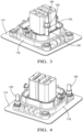
FIG. 3 illustrates a perspective view of a header portion of the electrical connector ofFIG. 2 according to some embodiments; -
FIG. 4 illustrates an alternative perspective view of the header portion ofFIG. 3 according to some embodiments; -
FIGs. 5 to 7 illustrate a mating sequence of the electrical connector ofFIG. 2 according to some embodiments; -
FIGs. 8A and 8B illustrate close up views of vibration resistant retaining features of the electrical connector ofFIG. 2 according to some embodiments; -
FIG. 9 illustrates a perspective view an electrical connector in a pre-staged condition according to some embodiments; and -
FIG. 10 illustrates a perspective view of the electrical connector ofFIG. 9 in a staged condition according to some embodiments. - In the following description, similar features of the various embodiments share the last two digits of the reference numbers shown in the figures.
- Conventional
electrical connectors 10 having aconnection assist lever 12, such as the example shown inFIG. 1 , provide ease of mating without the need for additional tools. Mechanical fastening of theelectrical connector 10 to amounting substrate 14 is provided by the interface connection of theassist lever 12 of theelectrical connector 10 to aconnector header 18 and the connection of theconnector header 18 to themounting substrate 14. The type ofelectrical connector 10 shown inFIG. 1 may be suitable for applications that experience lower levels of vibration. Since there are two separate connections between themounting substrate 14 and theelectrical connector 10, i.e., the connection between themounting substrate 14 and theconnector header 18; and connection between theconnector header 18 and theelectrical connector 10, there are also two points at which vibration may enter the connection system. - The non-limiting example of an electrical connector assembly 100 with a lever-based connector mating assist system that is shown in
FIGs. 2 through 8B is designed to resist vibration that may enter the connection system by mechanically fixing anelectrical connector 110 to themounting substrate 114 after theelectrical connector 110 andconnector header 118 are mated using theassist lever 112. Amounting stud 120 which attains this mechanical fixation extends from themounting substrate 114 and through theconnector header 118. One end of thismounting stud 120 is received within ahole 122 through amounting tab 124 that projects from theelectrical connector 110. - As shown in
FIG. 3 , themounting stud 120 is a double-ended bolt with two threadedportions first nut 130. One of the threadedportions 126 extends through theconnector header 118 into themounting substrate 114 and the other threadedportion 128 is received in thehole 122 of themounting tab 124. As shown inFIG. 2 , asecond nut 132 is threaded on the second threadedportion 128 to secure themounting tab 124 to themounting stud 120. Preferably, thefirst nut 130 is sized so that there is a hard point contact between themounting tab 124 and thefirst nut 130 when thesecond nut 132 is sufficiently tightened to secure themounting tab 124 to themounting stud 120. As additionally shown inFIG.2 themounting tab 124 may includegussets 134 between themounting tab 124 and the housing of theelectrical connector 110 to increase mechanical rigidity of themounting tab 124. - As shown in
FIG. 4 , there may be more than onemounting stud 120 extending from theconnector header 118 and more than onemounting tab 124 extending from the electrical connector 110 (not shown due to perspective view). It may be preferable to include twomounting studs 120 and mountingtabs 124 arranged diagonally as shown inFIG. 4 to resist vibration between theelectrical connector 110/connector header 118 interface. The number ofmounting studs 120 andmounting tabs 124 may be increased up to the number of mounting points for theconnector header 118 to themounting substrate 114 if desired. -
FIGs. 5 through 7 show a sequence of mating theelectrical connector 110 with theconnector header 118. InFIG. 5 , theelectrical connector 110 is properly aligned with theconnector header 118 which has been previously attached to themounting substrate 114 by the mounting stud 120 (and other fasteners, if needed). InFIG. 6 , theelectrical connector 110 is in apre-staged position 136 in which theassist lever 112 is engaged with theconnector header 118 in a first position. As theassist lever 112 is rotated from the first position to a second position, theelectrical connector 110 is drawn from thepre-staged position 136 to a stagedposition 138 in which theelectrical connector 110 andconnector header 118 are fully mated. As can be further observed inFIG. 6 , the second threadedportion 128 of themounting stud 120 is received within thehole 122 in themounting tab 124 as theelectrical connector 110 moves from thepre-staged position 136 to the stagedposition 138 as shown inFIG. 8A . Thesecond nut 132 may then be threaded on the second threadedportion 128 to secure themounting tab 124 to themounting stud 120 as shown inFIG. 8B . - In another embodiment of the electrical connector, hereafter referred to as
electrical connector 210, that is illustrated inFigs 9 and10 , themounting tab 224 extends from theassist lever 212 rather than the housing of theelectrical connector 210. In this embodiment, the second threaded portion of themounting stud 220 is received within a hole in themounting tab 224 as theassist lever 212 is rotated from the first position to the second position and theelectrical connector 210 is moved from itspre-staged position 236 to its stagedposition 238. The mountingtab 224 is then held in place by a second nut 232. This embodiment has the advantage of inhibiting movement of theassist lever 212 from the second position back to the first position thereby preventing disconnection of theelectrical connector 210 from theconnector header 218 before the second nut 232 is removed from the mountingstud 220. - Other embodiments of the electrical connector may be envisioned that include the mounting tab shown in
FIGs. 2-8B and along with the mounting tab shown inFIGs. 9-10 . - While the
assemblies same assemblies electrical connector connector header - While the examples presented herein is directed to electrical connector assemblies, alternative embodiments of the connector assembly may be envisioned that are configured to interconnect fiber optic cables, pneumatic tubes, hydraulic tubes, or a hybrid connector assembly having a combination of any of these types of conductors.
- While the invention has been described with reference to an exemplary embodiment(s), it will be understood by those skilled in the art that various changes may be made, and equivalents may be substituted for elements thereof without departing from the scope of the invention. In addition, many modifications may be made to adapt a particular situation or material to the teachings of the invention without departing from the essential scope thereof. Therefore, it is intended that the invention is not limited to the disclosed embodiment(s), but that the invention will include all embodiments falling within the scope of the appended claims.
- As used herein, 'one or more' includes a function being performed by one element, a function being performed by more than one element, e.g., in a distributed fashion, several functions being performed by one element, several functions being performed by several elements, or any combination of the above.
- It will also be understood that, although the terms first, second, etc. are, in some instances, used herein to describe various elements, these elements should not be limited by these terms. These terms are only used to distinguish one element from another. For example, a first contact could be termed a second contact, and, similarly, a second contact could be termed a first contact, without departing from the scope of the various described embodiments. The first contact and the second contact are both contacts, but they are not the same contact.
- The terminology used in the description of the various described embodiments herein is for the purpose of describing particular embodiments only and is not intended to be limiting. As used in the description of the various described embodiments and the appended claims, the singular forms "a", "an", and "the" are intended to include the plural forms as well, unless the context cltably indicates otherwise. It will also be understood that the term "and/or" as used herein refers to and encompasses any and all possible combinations of one or more of the associated listed items. It will be further understood that the terms "includes," "including," "comprises," and/or "comprising," when used in this specification, specify the presence of stated features, integers, steps, operations, elements, and/or components, but do not preclude the presence or addition of one or more other features, integers, steps, operations, elements, components, and/or groups thereof.
- As used herein, the term "if' is, optionally, construed to mean "when" or "upon" or "in response to determining" or "in response to detecting," depending on the context. Similarly, the phrase "if it is determined" or "if [a stated condition or event] is detected" is, optionally, construed to mean "upon determining" or "in response to determining" or "upon detecting [the stated condition or event]" or "in response to detecting [the stated condition or event]," depending on the context.
- Additionally, while terms of ordinance or orientation may be used herein these elements should not be limited by these terms. All terms of ordinance or orientation, unless stated otherwise, are used for purposes distinguishing one element from another, and do not denote any particular order, order of operations, direction or orientation unless stated otherwise.
Claims (15)
- A connector assembly, comprising:a connector header (118) configured to be attached to a mounting substrate (114) by a first mounting stud (120) extending through a first aperture defined by the connector header (118);a connector (110) configured to mate and unmate with the connector header (118) and having a mating assist lever (112) configured to attach and detach the connector to and from the connector header (118); anda mounting tab (124) defined by the connector header (118) and configured to attach the connector (110) to the first mounting stud (120) extending through a second aperture (122) defined by the mounting tab (124).
- The connector assembly according to claim 1, wherein the mounting tab (124) is integrally formed with the connector header (118).
- The connector assembly according to claim 1 or 2, wherein the first mounting stud (120) is threaded and wherein the connector header (118) is secured to the first mounting stud (120) by a first threaded nut and the mounting tab (124) is secured to the first nut (130) by a second threaded nut.
- The connector assembly according to claim 3, wherein the first nut (130) is integrally formed with the first stud.
- The connector assembly according to claim 3 or 4, wherein the mounting tab (124) is a first mounting tab (124), wherein the connector header (218) is configured to be attached to the mounting substrate (214) by a second mounting stud (220) extending through a third aperture defined by the connector header (218), and wherein the mating assist lever (212) defines a second mounting tab (224) configured to attach the mating assist lever (212) to the second mounting stud (220) extending through a fourth aperture defined by the second mounting tab (224).
- The connector assembly according to claim 5, wherein the second mounting stud (220) is threaded and wherein the connector header (218) is secured to the second mounting stud (220) by a third threaded nut and the second mounting tab (224) is secured to the second mounting stud (220) by a fourth threaded nut.
- The connector assembly according to claim 6, wherein the third nut is integrally formed with the second stud.
- The connector assembly according to any one of claims 5 to 6, wherein the first mounting stud (220) is arranged diagonally with the second mounting stud (220).
- The connector assembly according to any one of claims 5 to 8, wherein the mounting tab (224) is integrally formed with the mating assist lever (212).
- A method of assembling an electrical connector, comprising:inserting a first mounting stud (120) extending from a mounting substrate (114) through a first aperture defined by a connector header (118);placing a first nut (130) on the first mounting stud (120) and securing the connector header (118) to the mounting substrate (114);inserting the first mounting stud (120) through a second aperture of a mounting tab (124) defined by a connector configured to mate and unmate with the connector header (118) which has a mating assist lever (112) configured to attach and detach the connector to and from the connector header (118);activating the mating assist lever (112) to attach the connector to the connector header (118); andplacing a second nut (132) on the first mounting stud (120) and securing the mounting tab (124) to the first nut (130).
- The method according to claim 10, wherein the mounting tab (124) is integrally formed with the connector (110), wherein the first mounting stud (120) is threaded and, wherein the first nut (130) is integrally formed with the first stud.
- The method according to claim 10 or 11, wherein the mounting tab (124) is a first mounting tab (124), wherein the method further comprises:inserting a second mounting stud (220) extending from the mounting substrate (114) through a third aperture defined by a connector header (218);placing a third nut on the second mounting stud (220) and further securing the connector header (218) to the mounting substrate (114);inserting the second mounting stud (220) through a fourth aperture of a second mounting tab (224) defined by the mating assist lever (212); andplacing a fourth nut on the second mounting stud (220) and securing the second mounting tab (224) to the third nut.
- The method according to claim 12, wherein the second mounting stud (220) is threaded, wherein the first nut (130) is integrally formed with the first stud and, wherein the first mounting stud (220) is arranged diagonally with the second mounting stud (220).
- A method of assembling an electrical connector, comprising:inserting a first mounting stud (120) extending from a mounting substrate (114) through a first aperture defined by a connector header (118);placing a first nut (130) on the first mounting stud (120) and securing the connector header (118) to the mounting substrate (114);inserting the first mounting stud (120) through a second aperture of a mounting tab (124) defined by a mating assist lever (112) configured to attach and detach a connector (110) to and from the connector header (118);activating the mating assist lever (112) to attach the connector (110) to the connector header (118); andplacing a second nut (132) on the first mounting stud (120) and securing the mounting tab (124) to the first nut (130).
- The method according to claim 14, wherein the mounting tab (224) is integrally formed with the mating assist lever (212) and wherein the first mounting stud (220) is threaded, and wherein the first nut (130) is integrally formed with the mounting stud (220).
Applications Claiming Priority (2)
| Application Number | Priority Date | Filing Date | Title |
|---|---|---|---|
| US202263328219P | 2022-04-06 | 2022-04-06 | |
| US18/127,942 US20230327374A1 (en) | 2022-04-06 | 2023-03-29 | Vibration resistant connector system with mating assistance feature |
Publications (1)
| Publication Number | Publication Date |
|---|---|
| EP4258491A1 true EP4258491A1 (en) | 2023-10-11 |
Family
ID=85800351
Family Applications (1)
| Application Number | Title | Priority Date | Filing Date |
|---|---|---|---|
| EP23166285.9A Pending EP4258491A1 (en) | 2022-04-06 | 2023-04-03 | Vibration resistant connector system with mating assistance feature |
Country Status (2)
| Country | Link |
|---|---|
| US (1) | US20230327374A1 (en) |
| EP (1) | EP4258491A1 (en) |
Citations (5)
| Publication number | Priority date | Publication date | Assignee | Title |
|---|---|---|---|---|
| US5273453A (en) * | 1991-04-25 | 1993-12-28 | Molex Incorporated | Electrical connector with positive latch |
| JP2006092776A (en) * | 2004-09-21 | 2006-04-06 | Yazaki Corp | Device connection connector |
| US9583875B2 (en) * | 2013-10-25 | 2017-02-28 | Harting Electric Gmbh & Co. Kg | Plug connector with two types of locking devices |
| US20180254583A1 (en) * | 2015-09-10 | 2018-09-06 | Connec Limited | An electrical connection system for use in high power applications |
| US20190312394A1 (en) * | 2018-04-04 | 2019-10-10 | Commscope Technologies Llc | Ganged coaxial connector assembly |
Family Cites Families (13)
| Publication number | Priority date | Publication date | Assignee | Title |
|---|---|---|---|---|
| US4869681A (en) * | 1987-08-28 | 1989-09-26 | Siemens Aktiengesellschaft | Front plug system with lagging end contact arrangement |
| DE60133063T2 (en) * | 2000-06-05 | 2009-02-26 | Yazaki Corp. | Battery terminal and adapter for the pole of a battery |
| JP5776029B2 (en) * | 2011-10-11 | 2015-09-09 | スリオジャパン株式会社 | connector |
| US8882532B1 (en) * | 2013-12-09 | 2014-11-11 | Kenall Manufacturing Company | Driver box for an improved lighting system |
| WO2015111725A1 (en) * | 2014-01-24 | 2015-07-30 | 矢崎総業株式会社 | Service plug |
| JP2016048654A (en) * | 2014-08-28 | 2016-04-07 | タイコエレクトロニクスジャパン合同会社 | Connector assembly |
| JP6460404B2 (en) * | 2015-05-20 | 2019-01-30 | 株式会社オートネットワーク技術研究所 | Lever type connector |
| US9608357B1 (en) * | 2015-09-11 | 2017-03-28 | Delphi Technologies, Inc. | Right angle connector with terminal contact protection |
| JP6457982B2 (en) * | 2016-07-19 | 2019-01-23 | 矢崎総業株式会社 | Lever fitting type connector |
| FR3063838A1 (en) * | 2017-03-10 | 2018-09-14 | Radiall | CONNECTION ASSEMBLY OF A PLUG TO AN ELECTRONIC EQUIPMENT BOARD PANEL BASE, INTEGRATING A THERMAL REGULATION MEANS, PLUG AND SAME THEREFOR |
| US11291115B2 (en) * | 2018-03-30 | 2022-03-29 | Intel Corporation | Server microprocessor carrier with guiding alignment anti-tilt and automatic thermal interface material separation features for use in land grid array sockets |
| JP2020092059A (en) * | 2018-12-07 | 2020-06-11 | 株式会社エンプラス | socket |
| JP7091008B2 (en) * | 2020-04-24 | 2022-06-27 | 矢崎総業株式会社 | Mating connector |
-
2023
- 2023-03-29 US US18/127,942 patent/US20230327374A1/en active Pending
- 2023-04-03 EP EP23166285.9A patent/EP4258491A1/en active Pending
Patent Citations (5)
| Publication number | Priority date | Publication date | Assignee | Title |
|---|---|---|---|---|
| US5273453A (en) * | 1991-04-25 | 1993-12-28 | Molex Incorporated | Electrical connector with positive latch |
| JP2006092776A (en) * | 2004-09-21 | 2006-04-06 | Yazaki Corp | Device connection connector |
| US9583875B2 (en) * | 2013-10-25 | 2017-02-28 | Harting Electric Gmbh & Co. Kg | Plug connector with two types of locking devices |
| US20180254583A1 (en) * | 2015-09-10 | 2018-09-06 | Connec Limited | An electrical connection system for use in high power applications |
| US20190312394A1 (en) * | 2018-04-04 | 2019-10-10 | Commscope Technologies Llc | Ganged coaxial connector assembly |
Also Published As
| Publication number | Publication date |
|---|---|
| US20230327374A1 (en) | 2023-10-12 |
Similar Documents
| Publication | Publication Date | Title |
|---|---|---|
| EP3462544B1 (en) | Self-aligning busbar assembly | |
| CN107851919B (en) | Terminal fitting | |
| EP0384577A2 (en) | Electrical connector for fuel injector and terminals therefor | |
| US20020074149A1 (en) | Flexible intra-cabinet cable ring wire management system | |
| EP3133702B1 (en) | Connector system with disconnection evident connector position assurance feature | |
| EP2819248A1 (en) | Electrical connector with integrated moveable terminal stabilizer | |
| US12244094B2 (en) | Poke-in wire connector for power connector assembly | |
| US6435891B1 (en) | Mechanically assisted blind mate electrical connector | |
| US11437765B1 (en) | Snap-in electrical connector | |
| KR19990062930A (en) | Electrical connector assembly with terminal retention system | |
| KR101997200B1 (en) | Connector for Connecting Bus Bar | |
| EP2955797A1 (en) | Cable strain relief | |
| US10454214B1 (en) | Vehicle lighting device and method | |
| US9130362B2 (en) | Connector member including a locking element | |
| EP4297193A1 (en) | Electrical connector assembly with flexible and rigid terminal locking features | |
| EP0901197A2 (en) | Self-aligning connector system for electrical connectors | |
| US20230327374A1 (en) | Vibration resistant connector system with mating assistance feature | |
| JP2019110026A (en) | Mounting structure for connector | |
| US20250023293A1 (en) | Connector assembly and method of assembling such a connector assembly | |
| JP3060904B2 (en) | Bolted connector | |
| EP0668632A2 (en) | Electrical connector assembly | |
| EP4398426B1 (en) | Connector assembly with flexible lock and event driven wedge | |
| US20250309578A1 (en) | Interlocking connector design for electrical connectors | |
| EP4145645B1 (en) | Electrical connector and methods | |
| GB2544412A (en) | Vehicle earth point connector |
Legal Events
| Date | Code | Title | Description |
|---|---|---|---|
| PUAI | Public reference made under article 153(3) epc to a published international application that has entered the european phase |
Free format text: ORIGINAL CODE: 0009012 |
|
| STAA | Information on the status of an ep patent application or granted ep patent |
Free format text: STATUS: THE APPLICATION HAS BEEN PUBLISHED |
|
| AK | Designated contracting states |
Kind code of ref document: A1 Designated state(s): AL AT BE BG CH CY CZ DE DK EE ES FI FR GB GR HR HU IE IS IT LI LT LU LV MC ME MK MT NL NO PL PT RO RS SE SI SK SM TR |
|
| STAA | Information on the status of an ep patent application or granted ep patent |
Free format text: STATUS: REQUEST FOR EXAMINATION WAS MADE |
|
| 17P | Request for examination filed |
Effective date: 20240411 |
|
| RBV | Designated contracting states (corrected) |
Designated state(s): AL AT BE BG CH CY CZ DE DK EE ES FI FR GB GR HR HU IE IS IT LI LT LU LV MC ME MK MT NL NO PL PT RO RS SE SI SK SM TR |
|
| RAP1 | Party data changed (applicant data changed or rights of an application transferred) |
Owner name: APTIV TECHNOLOGIES AG |
|
| RAP3 | Party data changed (applicant data changed or rights of an application transferred) |
Owner name: APTIV TECHNOLOGIES AG |
|
| GRAP | Despatch of communication of intention to grant a patent |
Free format text: ORIGINAL CODE: EPIDOSNIGR1 |
|
| STAA | Information on the status of an ep patent application or granted ep patent |
Free format text: STATUS: GRANT OF PATENT IS INTENDED |
|
| INTG | Intention to grant announced |
Effective date: 20250911 |
|
| GRAS | Grant fee paid |
Free format text: ORIGINAL CODE: EPIDOSNIGR3 |
|
| GRAJ | Information related to disapproval of communication of intention to grant by the applicant or resumption of examination proceedings by the epo deleted |
Free format text: ORIGINAL CODE: EPIDOSDIGR1 |
|
| GRAL | Information related to payment of fee for publishing/printing deleted |
Free format text: ORIGINAL CODE: EPIDOSDIGR3 |
|
| STAA | Information on the status of an ep patent application or granted ep patent |
Free format text: STATUS: REQUEST FOR EXAMINATION WAS MADE |
|
| GRAP | Despatch of communication of intention to grant a patent |
Free format text: ORIGINAL CODE: EPIDOSNIGR1 |
|
| STAA | Information on the status of an ep patent application or granted ep patent |
Free format text: STATUS: GRANT OF PATENT IS INTENDED |
|
| P01 | Opt-out of the competence of the unified patent court (upc) registered |
Free format text: CASE NUMBER: UPC_APP_0013578_4258491/2025 Effective date: 20251114 |
|
| INTC | Intention to grant announced (deleted) | ||
| INTG | Intention to grant announced |
Effective date: 20251209 |
|
| GRAA | (expected) grant |
Free format text: ORIGINAL CODE: 0009210 |
|
| STAA | Information on the status of an ep patent application or granted ep patent |
Free format text: STATUS: THE PATENT HAS BEEN GRANTED |