EP4258430A1 - Secondary battery - Google Patents
Secondary battery Download PDFInfo
- Publication number
- EP4258430A1 EP4258430A1 EP22195840.8A EP22195840A EP4258430A1 EP 4258430 A1 EP4258430 A1 EP 4258430A1 EP 22195840 A EP22195840 A EP 22195840A EP 4258430 A1 EP4258430 A1 EP 4258430A1
- Authority
- EP
- European Patent Office
- Prior art keywords
- insulator
- extending portion
- lid body
- electrode assembly
- secondary battery
- Prior art date
- Legal status (The legal status is an assumption and is not a legal conclusion. Google has not performed a legal analysis and makes no representation as to the accuracy of the status listed.)
- Withdrawn
Links
Images


Classifications
-
- H—ELECTRICITY
- H01—ELECTRIC ELEMENTS
- H01M—PROCESSES OR MEANS, e.g. BATTERIES, FOR THE DIRECT CONVERSION OF CHEMICAL ENERGY INTO ELECTRICAL ENERGY
- H01M50/00—Constructional details or processes of manufacture of the non-active parts of electrochemical cells other than fuel cells, e.g. hybrid cells
- H01M50/10—Primary casings; Jackets or wrappings
- H01M50/102—Primary casings; Jackets or wrappings characterised by their shape or physical structure
- H01M50/103—Primary casings; Jackets or wrappings characterised by their shape or physical structure prismatic or rectangular
-
- H—ELECTRICITY
- H01—ELECTRIC ELEMENTS
- H01M—PROCESSES OR MEANS, e.g. BATTERIES, FOR THE DIRECT CONVERSION OF CHEMICAL ENERGY INTO ELECTRICAL ENERGY
- H01M50/00—Constructional details or processes of manufacture of the non-active parts of electrochemical cells other than fuel cells, e.g. hybrid cells
- H01M50/50—Current conducting connections for cells or batteries
- H01M50/572—Means for preventing undesired use or discharge
-
- H—ELECTRICITY
- H01—ELECTRIC ELEMENTS
- H01M—PROCESSES OR MEANS, e.g. BATTERIES, FOR THE DIRECT CONVERSION OF CHEMICAL ENERGY INTO ELECTRICAL ENERGY
- H01M50/00—Constructional details or processes of manufacture of the non-active parts of electrochemical cells other than fuel cells, e.g. hybrid cells
- H01M50/50—Current conducting connections for cells or batteries
- H01M50/502—Interconnectors for connecting terminals of adjacent batteries; Interconnectors for connecting cells outside a battery casing
- H01M50/503—Interconnectors for connecting terminals of adjacent batteries; Interconnectors for connecting cells outside a battery casing characterised by the shape of the interconnectors
-
- H—ELECTRICITY
- H01—ELECTRIC ELEMENTS
- H01M—PROCESSES OR MEANS, e.g. BATTERIES, FOR THE DIRECT CONVERSION OF CHEMICAL ENERGY INTO ELECTRICAL ENERGY
- H01M10/00—Secondary cells; Manufacture thereof
- H01M10/05—Accumulators with non-aqueous electrolyte
- H01M10/052—Li-accumulators
- H01M10/0525—Rocking-chair batteries, i.e. batteries with lithium insertion or intercalation in both electrodes; Lithium-ion batteries
-
- H—ELECTRICITY
- H01—ELECTRIC ELEMENTS
- H01M—PROCESSES OR MEANS, e.g. BATTERIES, FOR THE DIRECT CONVERSION OF CHEMICAL ENERGY INTO ELECTRICAL ENERGY
- H01M50/00—Constructional details or processes of manufacture of the non-active parts of electrochemical cells other than fuel cells, e.g. hybrid cells
- H01M50/10—Primary casings; Jackets or wrappings
- H01M50/147—Lids or covers
- H01M50/148—Lids or covers characterised by their shape
- H01M50/15—Lids or covers characterised by their shape for prismatic or rectangular cells
-
- H—ELECTRICITY
- H01—ELECTRIC ELEMENTS
- H01M—PROCESSES OR MEANS, e.g. BATTERIES, FOR THE DIRECT CONVERSION OF CHEMICAL ENERGY INTO ELECTRICAL ENERGY
- H01M50/00—Constructional details or processes of manufacture of the non-active parts of electrochemical cells other than fuel cells, e.g. hybrid cells
- H01M50/50—Current conducting connections for cells or batteries
- H01M50/502—Interconnectors for connecting terminals of adjacent batteries; Interconnectors for connecting cells outside a battery casing
- H01M50/514—Methods for interconnecting adjacent batteries or cells
- H01M50/516—Methods for interconnecting adjacent batteries or cells by welding, soldering or brazing
-
- H—ELECTRICITY
- H01—ELECTRIC ELEMENTS
- H01M—PROCESSES OR MEANS, e.g. BATTERIES, FOR THE DIRECT CONVERSION OF CHEMICAL ENERGY INTO ELECTRICAL ENERGY
- H01M50/00—Constructional details or processes of manufacture of the non-active parts of electrochemical cells other than fuel cells, e.g. hybrid cells
- H01M50/50—Current conducting connections for cells or batteries
- H01M50/502—Interconnectors for connecting terminals of adjacent batteries; Interconnectors for connecting cells outside a battery casing
- H01M50/514—Methods for interconnecting adjacent batteries or cells
- H01M50/517—Methods for interconnecting adjacent batteries or cells by fixing means, e.g. screws, rivets or bolts
-
- H—ELECTRICITY
- H01—ELECTRIC ELEMENTS
- H01M—PROCESSES OR MEANS, e.g. BATTERIES, FOR THE DIRECT CONVERSION OF CHEMICAL ENERGY INTO ELECTRICAL ENERGY
- H01M50/00—Constructional details or processes of manufacture of the non-active parts of electrochemical cells other than fuel cells, e.g. hybrid cells
- H01M50/50—Current conducting connections for cells or batteries
- H01M50/528—Fixed electrical connections, i.e. not intended for disconnection
-
- H—ELECTRICITY
- H01—ELECTRIC ELEMENTS
- H01M—PROCESSES OR MEANS, e.g. BATTERIES, FOR THE DIRECT CONVERSION OF CHEMICAL ENERGY INTO ELECTRICAL ENERGY
- H01M50/00—Constructional details or processes of manufacture of the non-active parts of electrochemical cells other than fuel cells, e.g. hybrid cells
- H01M50/50—Current conducting connections for cells or batteries
- H01M50/531—Electrode connections inside a battery casing
- H01M50/533—Electrode connections inside a battery casing characterised by the shape of the leads or tabs
-
- H—ELECTRICITY
- H01—ELECTRIC ELEMENTS
- H01M—PROCESSES OR MEANS, e.g. BATTERIES, FOR THE DIRECT CONVERSION OF CHEMICAL ENERGY INTO ELECTRICAL ENERGY
- H01M50/00—Constructional details or processes of manufacture of the non-active parts of electrochemical cells other than fuel cells, e.g. hybrid cells
- H01M50/50—Current conducting connections for cells or batteries
- H01M50/531—Electrode connections inside a battery casing
- H01M50/536—Electrode connections inside a battery casing characterised by the method of fixing the leads to the electrodes, e.g. by welding
-
- H—ELECTRICITY
- H01—ELECTRIC ELEMENTS
- H01M—PROCESSES OR MEANS, e.g. BATTERIES, FOR THE DIRECT CONVERSION OF CHEMICAL ENERGY INTO ELECTRICAL ENERGY
- H01M50/00—Constructional details or processes of manufacture of the non-active parts of electrochemical cells other than fuel cells, e.g. hybrid cells
- H01M50/50—Current conducting connections for cells or batteries
- H01M50/543—Terminals
- H01M50/547—Terminals characterised by the disposition of the terminals on the cells
- H01M50/55—Terminals characterised by the disposition of the terminals on the cells on the same side of the cell
-
- H—ELECTRICITY
- H01—ELECTRIC ELEMENTS
- H01M—PROCESSES OR MEANS, e.g. BATTERIES, FOR THE DIRECT CONVERSION OF CHEMICAL ENERGY INTO ELECTRICAL ENERGY
- H01M50/00—Constructional details or processes of manufacture of the non-active parts of electrochemical cells other than fuel cells, e.g. hybrid cells
- H01M50/50—Current conducting connections for cells or batteries
- H01M50/543—Terminals
- H01M50/564—Terminals characterised by their manufacturing process
- H01M50/567—Terminals characterised by their manufacturing process by fixing means, e.g. screws, rivets or bolts
-
- H—ELECTRICITY
- H01—ELECTRIC ELEMENTS
- H01M—PROCESSES OR MEANS, e.g. BATTERIES, FOR THE DIRECT CONVERSION OF CHEMICAL ENERGY INTO ELECTRICAL ENERGY
- H01M50/00—Constructional details or processes of manufacture of the non-active parts of electrochemical cells other than fuel cells, e.g. hybrid cells
- H01M50/50—Current conducting connections for cells or batteries
- H01M50/572—Means for preventing undesired use or discharge
- H01M50/584—Means for preventing undesired use or discharge for preventing incorrect connections inside or outside the batteries
- H01M50/586—Means for preventing undesired use or discharge for preventing incorrect connections inside or outside the batteries inside the batteries, e.g. incorrect connections of electrodes
-
- H—ELECTRICITY
- H01—ELECTRIC ELEMENTS
- H01M—PROCESSES OR MEANS, e.g. BATTERIES, FOR THE DIRECT CONVERSION OF CHEMICAL ENERGY INTO ELECTRICAL ENERGY
- H01M50/00—Constructional details or processes of manufacture of the non-active parts of electrochemical cells other than fuel cells, e.g. hybrid cells
- H01M50/50—Current conducting connections for cells or batteries
- H01M50/572—Means for preventing undesired use or discharge
- H01M50/584—Means for preventing undesired use or discharge for preventing incorrect connections inside or outside the batteries
- H01M50/59—Means for preventing undesired use or discharge for preventing incorrect connections inside or outside the batteries characterised by the protection means
- H01M50/593—Spacers; Insulating plates
-
- H—ELECTRICITY
- H01—ELECTRIC ELEMENTS
- H01M—PROCESSES OR MEANS, e.g. BATTERIES, FOR THE DIRECT CONVERSION OF CHEMICAL ENERGY INTO ELECTRICAL ENERGY
- H01M50/00—Constructional details or processes of manufacture of the non-active parts of electrochemical cells other than fuel cells, e.g. hybrid cells
- H01M50/50—Current conducting connections for cells or batteries
- H01M50/572—Means for preventing undesired use or discharge
- H01M50/584—Means for preventing undesired use or discharge for preventing incorrect connections inside or outside the batteries
- H01M50/59—Means for preventing undesired use or discharge for preventing incorrect connections inside or outside the batteries characterised by the protection means
- H01M50/595—Tapes
-
- H—ELECTRICITY
- H01—ELECTRIC ELEMENTS
- H01M—PROCESSES OR MEANS, e.g. BATTERIES, FOR THE DIRECT CONVERSION OF CHEMICAL ENERGY INTO ELECTRICAL ENERGY
- H01M50/00—Constructional details or processes of manufacture of the non-active parts of electrochemical cells other than fuel cells, e.g. hybrid cells
- H01M50/10—Primary casings; Jackets or wrappings
- H01M50/172—Arrangements of electric connectors penetrating the casing
- H01M50/174—Arrangements of electric connectors penetrating the casing adapted for the shape of the cells
- H01M50/176—Arrangements of electric connectors penetrating the casing adapted for the shape of the cells for prismatic or rectangular cells
-
- H—ELECTRICITY
- H01—ELECTRIC ELEMENTS
- H01M—PROCESSES OR MEANS, e.g. BATTERIES, FOR THE DIRECT CONVERSION OF CHEMICAL ENERGY INTO ELECTRICAL ENERGY
- H01M50/00—Constructional details or processes of manufacture of the non-active parts of electrochemical cells other than fuel cells, e.g. hybrid cells
- H01M50/50—Current conducting connections for cells or batteries
- H01M50/543—Terminals
- H01M50/552—Terminals characterised by their shape
- H01M50/553—Terminals adapted for prismatic, pouch or rectangular cells
-
- Y—GENERAL TAGGING OF NEW TECHNOLOGICAL DEVELOPMENTS; GENERAL TAGGING OF CROSS-SECTIONAL TECHNOLOGIES SPANNING OVER SEVERAL SECTIONS OF THE IPC; TECHNICAL SUBJECTS COVERED BY FORMER USPC CROSS-REFERENCE ART COLLECTIONS [XRACs] AND DIGESTS
- Y02—TECHNOLOGIES OR APPLICATIONS FOR MITIGATION OR ADAPTATION AGAINST CLIMATE CHANGE
- Y02E—REDUCTION OF GREENHOUSE GAS [GHG] EMISSIONS, RELATED TO ENERGY GENERATION, TRANSMISSION OR DISTRIBUTION
- Y02E60/00—Enabling technologies; Technologies with a potential or indirect contribution to GHG emissions mitigation
- Y02E60/10—Energy storage using batteries
Definitions
- Embodiments described herein relate generally to a secondary battery.
- secondary batteries with high energy density for example, lithium-ion secondary batteries
- Such secondary batteries are constituted by accommodating an electrode assembly and a non-aqueous electrolyte in a rectangular parallelepiped outer container made of aluminum or aluminum alloy.
- an insulator is used as a spacer to maintain the interval.
- a secondary battery comprises an outer container including a pair of long side walls opposing each other with an interval therebetween and a lid body fixed to one end of each of the pair of long side walls, an electrode assembly including a group of electrodes and current collecting tabs extending from the group of electrodes, and accommodated in the outer container, an output terminal provided on the lid body, a lead provided between the electrode assembly and the lid body inside the outer container and electrically connecting the output terminal and the current collecting tabs to each other, and including a junction opposing the lid body and connected to the output terminal, a first extending portion extending from the junction along an inner surface of one of the long side walls and a second extending portion extending from the junction along an inner surface of the other one of the long side walls, a first insulator provided between the electrode assembly and the lid body inside the outer container, disposed to oppose the inner surface of one of the long side walls and including an inner surface engaged with an outer surface of the first extending portion and a second insulator provided between the electrode assembly and
- a secondary battery of the first embodiment will now be described in detail.
- FIG. 1 is a perspective view showing an appearance of the secondary battery of the first embodiment.
- a secondary battery 10 is a non-aqueous electrolytic secondary battery, such as a lithium ion battery, and comprises a flat and substantially rectangular parallelepiped-shaped outer container 12 and an electrode assembly 30, which will be later described, accommodated with a non-aqueous electrolyte inside the outer container 12.
- the outer container 12 is, for example, a resin container formed of resin.
- the outer container 12 includes a container body 16 with an opened upper end and a plate-like lid body 14 fixed to the container body 16 to close the opening of the container body 16, and is formed to be airtight inside.
- the container body 16 and the lid body 14 are formed of an electrically insulating resin.
- the lid body 14 comprises a pair of output terminals 20 and an inlet 29.
- the longitudinal direction of the lid body 14 and the container body 16 is defined as an X direction
- the width direction of the lid body 14 and the container body 16, which is orthogonal to the longitudinal direction X is defined as a Y direction
- the height direction of the container body 16 is defined as a Z direction.
- outer container 12 is not limited to a resin-made, but it may as well be a metal container formed of a metal such as aluminum alloy, iron or stainless steel.
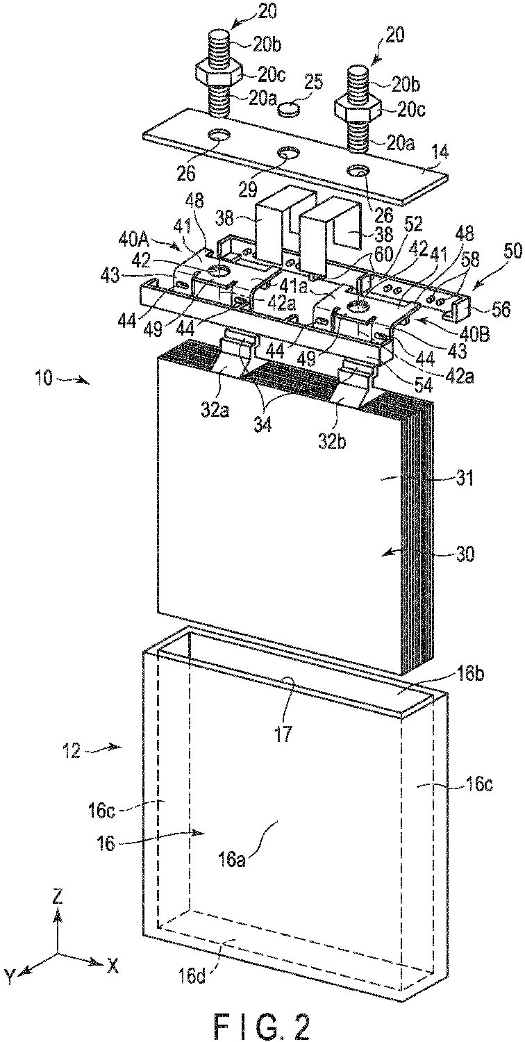
- FIG. 2 is an exploded perspective view of the secondary battery shown in FIG. 1 .
- the container body 16 of the outer container 12 includes a rectangular-shaped long side wall 16a, a rectangular-shaped long side wall 16b opposing parallel with an interval to the long side wall 16a, a pair of short side walls 16c opposing each other and a bottom wall 16d. Upper edges of the pair of long side walls 16a and 16b and upper edges of the pair of short side walls 16c define a rectangular-shaped upper opening 17.
- the lid body 14 is formed into a rectangular plate with a size approximately equal to that of the upper opening 17.
- the lid body 14 is fixed to the container body 16 while closing the upper opening 17.
- the lid body 14 comprises a pair of circular perforations 26 formed therein.
- Each of the perforations 26 is a through hole formed to penetrate the lid body 14 in the height direction (thickness direction) Z.
- the pair of perforations 26 are located in respective end portions of the lid body 14 along the longitudinal direction X and are spaced apart from each other along the longitudinal direction X.
- an inlet 29 is located between the pair of perforations 26, an inlet 29 is located. After pouring the non-aqueous electrolyte into the outer container 12 through the inlet 29, the inlet 29 is sealed with, for example, a disk-shaped sealing lid 25.
- the output terminals 20 are each formed into a column shape extending along the height direction Z, and includes a first external thread portion 20a formed at one end portion, a second external thread portion 20b formed at the other end portion and an annular flange portion 20c located between the first external thread portion 20a and the second external thread portion 20b, which are integrated into one body.
- the flange portion 20c is formed into a hexagonal shape, for example, and constitutes a nut.
- the output terminals 20 are attached to the lid body 14 as the first external thread portions 20a are inserted into the respective perforations 26 of the lid body 14.
- the electrode assembly 30 accommodated in the outer container 12 is constituted by, for example, stacking a plurality of sheet-shaped positive electrode plates and negative electrode plates alternately one on another with separators interposed between each pair.
- the positive electrode plates each include a plate-shaped positive electrode current collector, and a positive electrode active material layer formed on at least one side of the positive electrode current collector, and a positive electrode current collecting tab 32a extending from one end of the positive electrode current collector in the height direction Z.
- the negative electrode plates each include a plate-shaped negative electrode collector, a negative electrode active material layer formed on at least one side of the negative electrode collector, and a negative electrode current collection tab 32b extending from one end of the negative electrode current collector along the height direction Z.
- the separator has electrically insulating properties and electrically insulates the negative electrode plate and the positive electrode plate from each other.
- the current collectors and current collecting tabs of the negative electrode plates and positive electrode plates are each formed from a metal foil having a thickness of about 5 to 50 ⁇ m, for example.
- the material of the metal foil may vary depending on the type of the active material used for the positive and negative electrodes, but, for example, aluminum, aluminum alloy, copper, or copper alloy may be used.
- the positive electrode current collecting tabs 32a extend outward from one end of the electrode assembly (a group of electrode) 30 and are stacked in the width direction Y.
- the extending portions of the positive electrode current collecting tabs 32a may be collectively held by a backup lead 34 bent into a U-shape.
- the positive electrode current collecting tabs 32a are located on one end side of the electrode assembly 30 in the longitudinal direction X.
- the negative electrode current collecting tabs 32b extend outward from one end of the electrode assembly 30 and are stacked in the width direction Y. The extending portions of the negative electrode current collecting tabs 32b are collectively held by a backup lead 34 bent into a U-shape. The negative electrode current collecting tabs 32b are located at the other end side of the electrode assembly 30 in the longitudinal direction X.
- the positive electrode current collecting tabs 32a and the negative electrode current collecting tabs 32b extend in the same direction from one end and of the electrode assembly 30, and are located at intervals from each other along the longitudinal direction X of the electrode assembly 30.
- the positive electrode current collecting tabs 32a and the negative electrode current collecting tabs 32b are springy and have an urging force upward in the height direction Z.
- the electrode assembly 30 configured as described above is accommodated inside the container body 16 in such a manner that one end surface of the electrode assembly 30, the positive electrode current collecting tabs 32a and the negative electrode current collecting tabs 32b are directed to oppose the lid body 14 along the height direction Z. Between the one end surface of the electrode assembly 30 and the lid body 14, a predetermined interval is provided.
- the secondary battery 10 comprises a pair of insulators 50, an adhesive member 38, a positive electrode lead 40A and a negative electrode lead 40B provided in a space between the electrode assembly 30 and the lid body 14 inside the outer container 12.
- the insulators 50 are formed, for example, of an electrically insulating resin.
- the insulator 50 is formed into a frame shape to enclose the space between the lid body 14 and the electrode assembly 30, and is disposed in contact with an inner surface of the container body 16.
- the insulators 50 electrically insulate the positive electrode lead 40A, the negative electrode lead 40B, the positive electrode current collecting tabs 32a, and positive electrode current collecting tabs 32b from the container body 16, and also functions as a spacer to maintain the interval between the lid body 14 and the electrode assembly 30.
- an insulator 50 may be formed by combining a pair of divided insulator members 50, into one to form a frame body.
- the shape of the insulator 50 will be described in detail later in the explanation of FIG. 5 .
- the adhesive member 38 is, for example, a strip-like adhesive tape.
- the adhesive member 38 holds each insulator 50 and the electrode assembly 30 in an integrated state. The position where the adhesive member 38 is attached will be described later in the explanation of FIG. 6 .
- the positive electrode lead 40A is located between the insulators 50 in the width direction Y, and electrically connects the output terminals 20 and the positive electrode current collecting tabs 32a respectively to each other.
- the negative electrode lead 40B is located between the insulators 50 in the width direction Y and electrically connects the output terminals 20 and the negative electrode current collecting tabs 32b respectively to each other.
- the positive electrode lead 40A and the negative electrode lead 40B have respective configurations and shapes identical to each other.
- FIG. 3 is a perspective view of the positive electrode lead
- FIG. 4 is a perspective view of the negative electrode lead as viewed from a different direction.
- the positive electrode lead 40A is constituted by bending a conductive metal sheet material.
- the positive electrode lead 40A includes a rectangular junction 41, a rectangular first extending portion 45 extending from one side edge of the rectangular junction 41 so as to be substantially perpendicular to the rectangular junction 41, and a pair of rectangular second extending portions 43 extending from respective ends of the other side edge of the junction 41 so as to be substantially perpendicular to the junction 41, which are integrated into one body.
- the junction 41 is formed into the shape of a rectangular plate with a pair of side edges extending along the longitudinal direction X, and includes an upper surface 41a opposing the lid body 14 and a lower surface 41b located on an opposite side to the upper surface 41a.
- the junction 41 includes a pair of first engagement projecting portions 48 projecting in a surface direction from respective end portions of one side edge beyond the first extending portion 45, and a second engagement projecting portion 49 projecting in the surface direction from a central portion of the other side edge beyond the second extending portion 43.
- the junction 41 includes a cylindrical protruding portion 47 provided to protrude substantially from a central portion of the lower surface 41b and an internal thread portion 42 formed to penetrate the junction 41 and the protruding portion 47 along the height direction Z.
- the internal thread portion 42 has a length of 2 mm or more in a direction along an axis 42a and is provided for the first external thread portion 20a of the output terminal 20 to be screwed therein.
- the first extending portion 45 extends out in the form of a plate along the height direction Z and includes an outer surface 45a opposing parallel to the long side wall 16b of the container body 16. Recesses are formed respectively by depressing a pair of side edges of the first extending portion 45 extending in the height direction Z, and thus first engaged portions 46 are formed.
- Each of the second extending portions 43 includes an outer surface 43a opposing parallel to the long side wall 16a of the container body 16.
- Each second extending portion 43 includes a second engaged portion 44, which is a through hole formed to penetrate the second extending portion 43 along the width direction Y.
- the second engaged portion 44 is, for example, an opening elongated along the longitudinal direction X.
- FIG. 5 is a perspective view of one insulator 50.
- the insulators 50 have shapes identical to each other.
- the insulator 50 is formed into a slender plate extending along the longitudinal direction X, and includes an inner surface 52 which engages with the positive electrode lead 40A and the negative electrode lead 40B, an outer surface 54 (see FIG. 2 ) which is in contact with the inner surface of the container body 16, an upper surface 53 opposing the lid body 14 between the inner surface 52 and the outer surface 54, and a connecting portion 56 formed by bending both ends of the longitudinal direction X along the width direction Y.
- the inner surface 52 of the insulator 50 includes two ribs 58 protruding from the inner surface in the central portion along the longitudinal direction X, and a plurality of, for example, four engagement projections 60 formed to project therefrom between the ribs 58 and the connecting portion 56.
- the ribs 58 each include an end surface 59 opposing the lid body 14 and located on the same plane as that of the upper surface 53.
- the ribs 58 increase the rigidity of the insulator 50 and prevent deflection of the adhesive member 38.
- the engagement projections 60 are located in positions and with dimensions by which they can be engaged with the first engaged portions 46 or the second engaged portions 44 of the positive electrode lead 40A or the negative electrode lead 40B, respectively.
- the connecting portion 56 includes a projecting portion 56a on one end surface and a recess portion 56b on the other end surface.
- the projecting portion 56a and the recess portion 56b are formed in positions and with dimensions by which they can engage each other.
- the pair of insulators 50 are coupled together as the projecting portion 56a of one insulator 50 and the recess portion 56b of the other insulator 50 56b are engaged with each other, and the recess portion 56b of one insulator and the projecting portion 56a of the other insulator 50 are engaged with each other. Further, by coupling the pair of insulators 50 with each other, the rib 58 of one insulator 50 is brought into contact with the rib 58 of the other insulator 50.
- FIG. 6 is a perspective view showing the electrode assembly 30, the positive electrode lead 40A, the negative electrode lead 40B, the insulator 50 and the adhesive members 38. Further, parts of the positive electrode lead 40A, the negative electrode lead 40B and the pair of insulators 50 are indicated by dashed lines.
- the pair of insulators 50 are coupled with each other, and the inner surfaces 52 of the pair of insulators and the first extending portion 45 and the second extending portions 43 of the positive electrode lead 40A and the negative electrode lead 40B are engaged to be connected to each other.
- the adhesive member 38 retains the state where the electrode assembly 30, the positive electrode lead 40A, the negative electrode lead 40B and each insulator 50 are integrated together. In more detail, by the urging force of the positive electrode current collecting tabs 32a and the negative electrode current collecting tabs 32b, the positive electrode lead 40A, the negative electrode lead 40B and each insulator 50 are prevented from separating from the electrode assembly 30.
- the adhesive member 38 is attached over the pair of side surfaces 31 along the width direction Y of the electrode assembly 30, the outer surface 54 of each insulator 50 and the upper surface 53 of each insulator 50.
- the adhesive member 38 is attached to overlap the end surfaces 59 of the ribs 58. With this structure, it is possible to prevent the adhesive member 38 from deflecting toward the height direction Z.
- the position where the adhesive member 38 is attached is not limited to the above-described position, but it may be any position as long as the insulator 50 is not detached from the electrode assembly 30.
- the adhesive member may be attached along the longitudinal direction X such that it is overlaid on the outer surface 54 of each insulator 50 and the pair of side surfaces 31 of the electrode assembly 30.
- FIG. 7 is a cross-sectional view taken along line B-B shown in FIG. 6 as viewed from the direction of arrow C, in which the positive electrode lead 40A and the insulator 50 are extracted.
- the positive electrode lead 40A is coupled as the first engaged portion 46 of the positive electrode lead 40A and the engagement projection 60 of the insulator 50 are engaged with each other. Between the first engaged portion 46 and the engagement projection 60, a gap is made in the longitudinal direction X. The first engaged portion 46 and the engagement projection 60 are brought into contact with each other in the height direction Z.
- FIG. 8 is a cross-sectional view taken along line B-B shown in FIG. 6 as viewed from the direction of arrow D, in which the negative electrode lead 40A and the insulator 50 are extracted.
- the positive electrode lead 40A is coupled as the second engaged portion 44 of positive electrode lead 40A and the engagement projection 60 of the insulator 50 are engaged with each other. Between the second engaged portion 44 and the engagement projection 60, a gap is made along the longitudinal direction X. Further, the second engaged portion 44 and the engagement projection 60 are brought into contact with each other in the height direction Z.
- the positive electrode lead 40A is configured to be movable in the longitudinal direction X with respect to the insulator 50, while its movement along the height direction Z is restricted.
- the reason for restricting the movement of the positive electrode lead 40A in the height direction Z is to prevent the positive electrode lead 40A from displacing relatively with respect to each insulator 50 by the urging force of the positive current collecting tabs 32a and the negative current collecting tabs 32b.
- FIG. 9 is a cross-sectional view taken along line A-A in FIG. 1 .
- the outer container 12 includes a container body 16 with an opening at the upper end thereof and the lid body 14 which closes the opening of the container body 16.
- the electrode assembly 30, the positive electrode lead 40A and the pair of insulators 50 are accommodated inside the outer container 12. Meanwhile, the output terminal 20 is attached to the outer container 12 from the outside of the outer container 12 (from above the lid body 14).
- the electrode assembly 30 is located between the pair of long side walls 16a and 16b of the container body 16, and includes the positive electrode current collecting tab 32a extending toward the lid body 14. The distal end of the positive electrode current collecting tab 32a is held by the backup lead 34 to be connected to the first extending portion 45 of the positive electrode lead 40A.
- the pair of insulators 50 are aligned along the width direction Y and located between the electrode assembly 30 and the lid body 14. The outer surface of each insulator 50 is in contact with the inner surface of the container body 16, and the inner surface of each insulator 50 is engaged with the outer surface of the positive electrode lead 40A.
- the positive electrode lead 40A is located between the electrode assembly 30 and the lid body 14, and is coupled with the insulator 50 as the first engaged portion 46 and the second engaged portion 44 and the engagement projection 60 of each insulator 50 are respectively engaged with each other. (For the first engaged portion 46, the second engaged portion 44 and the engagement projection 60, see FIGS. 3, 4 and 5 ).
- the positive electrode lead 40A includes the junction 41 in contact with the inner surface of the lid body 14, the first extending portion 45 extending from the junction 41 along the long side wall 16a, and the second extending portion 43 extending from the junction 41 along the long side wall 16b.
- the junction 41 includes the first engagement projecting portion 48, the second engagement projecting portion 49, the protruding portion 47 protruding from the lower surface of the junction 41, and the internal thread portion 42 formed to penetrate the junction 41 and the protruding portion 47.
- the first engagement projecting portion 48 is brought into contact with the upper surface 53 of one insulator 50 and the second engagement projecting portion 49 is brought into contact with the upper surface 53 of the other insulator 50, and thus the positive electrode lead 40A is held by each insulator 50.
- the outer surface 45a of the first extending portion 45 is brought into contact with the inner surface 52 of one insulator 50 and the outer surface of the second extending portion 43 is brought into contact with the inner surface 52 of the other insulator 50.
- the positive electrode lead 40A is engaged with the insulator 50 as the outer surfaces 43a of the first extending portion 45 and the second extending portion 43 are brought into contact with the inner surface 52 of the insulator 50.
- the output terminal 20 includes the first external thread portion 20a, the second external thread portion 20b and the flange portion 20c located between the first external thread and the second external thread.
- the first external thread portion 20a is threaded into the internal thread portion 42 of the positive electrode lead 40A through the perforation 26 of the lid body 14 until the flange portion 20c is brought into contact with the outer surface of the lid body 14.
- the output terminal 20 and the positive electrode lead 40A are fixed to the outer and inner surfaces of the lid body 14, respectively, and the output terminal 20 is electrically connected to the positive electrode lead 40A.
- the secondary battery 10 includes the outer container 12, the electrode assembly 30, the output terminal 20, the leads (the positive electrode lead 40A and the negative electrode lead 40B) and the pair of insulators 50.
- the leads each include the first extending portion 45 and the second extending portion 43 which engage with the inner surface 52 of each insulator 50.
- the adhesive member 38 when the adhesive member 38 is attached to the pair of side surfaces 31 of the electrode assembly 30 and the outer surface 54 of the insulator 50, the integrated state of the electrode assembly 30 and the insulator 50 can be retained, thereby facilitating the accommodation thereof into the container body 16.
- the first engaged portion 46 and the second engaged portion 44 are provided in the lead and the engagement projection 60 is provided in each insulator 50, and thus it is easy to position the lead and to connect it to the output terminal 20. In other words, a secondary battery that is easy to assemble can be obtained.
- FIG. 10 is a perspective view showing an electrode assembly 30, a positive electrode lead 40A, a negative electrode lead 40B and insulators 50 according to the second embodiment.
- the secondary battery 10 has a configuration similar to that of the first embodiment, except for the configuration described in the second embodiment.
- the secondary battery of the second embodiment is configured without the adhesive member 38.
- the electrode assembly 30 and each insulator 50 are fixed by an adhesive 39.
- the adhesive 39 is provided between the electrode assembly 30 and each insulator 50 in the height direction Z.
- the electrode assembly 30 and the insulating body 50 can be retained in an integrated state, which facilitates the accommodation thereof in the container body 16. In other words, a secondary battery that is easy to assemble can be obtained.
Landscapes
- Chemical & Material Sciences (AREA)
- Chemical Kinetics & Catalysis (AREA)
- Electrochemistry (AREA)
- General Chemical & Material Sciences (AREA)
- Engineering & Computer Science (AREA)
- Manufacturing & Machinery (AREA)
- Materials Engineering (AREA)
- Connection Of Batteries Or Terminals (AREA)
- Secondary Cells (AREA)
- Cell Separators (AREA)
Abstract
According to one embodiment, a secondary battery (10) includes an outer container (12) including a pair of long side walls (16a, 16b) and a lid body (14), an electrode assembly (30), an output terminal (20), a lead (40A, 40B) including a junction (41), a first insulator (50), and a second insulator (50). The lead (40A, 40B) includes a first extending portion (45) extending from the junction (41), and a second extending portion (43) extending from the junction (41). The first insulator (50) includes an inner surface engaged with an outer surface of the first extending portion (45). The second insulator (50) includes an inner surface engaged with an outer surface of the second extending portion (43).
Description
- Embodiments described herein relate generally to a secondary battery.
- In recent years, secondary batteries with high energy density, for example, lithium-ion secondary batteries, have been widely used as power sources for electronic devices and electric vehicles. Such secondary batteries are constituted by accommodating an electrode assembly and a non-aqueous electrolyte in a rectangular parallelepiped outer container made of aluminum or aluminum alloy. Here, it is known that between a lid of the outer container and the electrode assembly, a predetermined interval is provided, and an insulator is used as a spacer to maintain the interval.
-
-
FIG. 1 is a perspective view showing an appearance of a secondary battery of the first embodiment. -
FIG. 2 is an exploded perspective view of the secondary battery shown inFIG. 1 . -
FIG. 3 is a perspective view showing a lead. -
FIG. 4 is a perspective view of the lead shown inFIG. 3 as viewed from a rear surface side. -
FIG. 5 is a perspective view showing one of insulators. -
FIG. 6 is a perspective view showing an electrode assembly, a negative electrode lead, a positive electrode lead, insulators and an adhesive member. -
FIG. 7 is a cross-sectional view taken along line B-B shown inFIG. 6 as viewed from a direction of arrow C, showing together the negative electrode lead and insulator extracted. -
FIG. 8 is a cross-sectional view taken along line B-B shown inFIG. 6 as viewed from a direction of arrow D, showing together the negative electrode lead and the insulator extracted. -
FIG. 9 is a cross-sectional view taken along line A-A inFIG. 1 . -
FIG. 10 is a perspective view showing an electrode assembly, a positive electrode lead, a negative electrode lead and an insulator of a secondary battery according to the second embodiment. - In general, according to one embodiment, a secondary battery comprises an outer container including a pair of long side walls opposing each other with an interval therebetween and a lid body fixed to one end of each of the pair of long side walls, an electrode assembly including a group of electrodes and current collecting tabs extending from the group of electrodes, and accommodated in the outer container, an output terminal provided on the lid body, a lead provided between the electrode assembly and the lid body inside the outer container and electrically connecting the output terminal and the current collecting tabs to each other, and including a junction opposing the lid body and connected to the output terminal, a first extending portion extending from the junction along an inner surface of one of the long side walls and a second extending portion extending from the junction along an inner surface of the other one of the long side walls, a first insulator provided between the electrode assembly and the lid body inside the outer container, disposed to oppose the inner surface of one of the long side walls and including an inner surface engaged with an outer surface of the first extending portion and a second insulator provided between the electrode assembly and the lid body inside the outer container, disposed to oppose an inner surface of the other one of the long side walls, and including an inner surface engaged with an outer surface of the second extending portion.
- Embodiments will be described hereinafter with reference to the accompanying drawings. The disclosure is merely an example, and proper changes within the spirit of the invention, which are easily conceivable by a skilled person, are included in the scope of the invention as a matter of course. In addition, in some cases, in order to make the description clearer, the widths, thicknesses, shapes, etc., of the respective parts are schematically illustrated in the drawings, compared to the actual modes. However, the schematic illustration is merely an example, and adds no restrictions to the interpretation of the invention. Besides, in the specification and drawings, the same or similar elements as or to those described in connection with preceding drawings or those exhibiting similar functions are denoted by like reference numerals, and a detailed description thereof is omitted unless otherwise necessary.
- A secondary battery of the first embodiment will now be described in detail.
-
FIG. 1 is a perspective view showing an appearance of the secondary battery of the first embodiment. - As shown in
FIG. 1 , asecondary battery 10 is a non-aqueous electrolytic secondary battery, such as a lithium ion battery, and comprises a flat and substantially rectangular parallelepiped-shapedouter container 12 and anelectrode assembly 30, which will be later described, accommodated with a non-aqueous electrolyte inside theouter container 12. Theouter container 12 is, for example, a resin container formed of resin. Theouter container 12 includes acontainer body 16 with an opened upper end and a plate-like lid body 14 fixed to thecontainer body 16 to close the opening of thecontainer body 16, and is formed to be airtight inside. In the first embodiment, as described above, thecontainer body 16 and thelid body 14 are formed of an electrically insulating resin. - The
lid body 14 comprises a pair ofoutput terminals 20 and aninlet 29. - Here, the longitudinal direction of the
lid body 14 and thecontainer body 16 is defined as an X direction, the width direction of thelid body 14 and thecontainer body 16, which is orthogonal to the longitudinal direction X is defined as a Y direction, and the height direction of thecontainer body 16 is defined as a Z direction. - Note that the
outer container 12 is not limited to a resin-made, but it may as well be a metal container formed of a metal such as aluminum alloy, iron or stainless steel. -
FIG. 2 is an exploded perspective view of the secondary battery shown inFIG. 1 . - As shown in
FIG. 2 , thecontainer body 16 of theouter container 12 includes a rectangular-shapedlong side wall 16a, a rectangular-shapedlong side wall 16b opposing parallel with an interval to thelong side wall 16a, a pair ofshort side walls 16c opposing each other and abottom wall 16d. Upper edges of the pair oflong side walls short side walls 16c define a rectangular-shapedupper opening 17. - The
lid body 14 is formed into a rectangular plate with a size approximately equal to that of theupper opening 17. Thelid body 14 is fixed to thecontainer body 16 while closing theupper opening 17. - The
lid body 14 comprises a pair ofcircular perforations 26 formed therein. Each of theperforations 26 is a through hole formed to penetrate thelid body 14 in the height direction (thickness direction) Z. The pair ofperforations 26 are located in respective end portions of thelid body 14 along the longitudinal direction X and are spaced apart from each other along the longitudinal direction X. Between the pair ofperforations 26, aninlet 29 is located. After pouring the non-aqueous electrolyte into theouter container 12 through theinlet 29, theinlet 29 is sealed with, for example, a disk-shaped sealing lid 25. - The
output terminals 20 are each formed into a column shape extending along the height direction Z, and includes a firstexternal thread portion 20a formed at one end portion, a secondexternal thread portion 20b formed at the other end portion and anannular flange portion 20c located between the firstexternal thread portion 20a and the secondexternal thread portion 20b, which are integrated into one body. Theflange portion 20c is formed into a hexagonal shape, for example, and constitutes a nut. Theoutput terminals 20 are attached to thelid body 14 as the firstexternal thread portions 20a are inserted into therespective perforations 26 of thelid body 14. - As shown in
FIG. 2 , theelectrode assembly 30 accommodated in theouter container 12 is constituted by, for example, stacking a plurality of sheet-shaped positive electrode plates and negative electrode plates alternately one on another with separators interposed between each pair. The positive electrode plates each include a plate-shaped positive electrode current collector, and a positive electrode active material layer formed on at least one side of the positive electrode current collector, and a positive electrodecurrent collecting tab 32a extending from one end of the positive electrode current collector in the height direction Z. The negative electrode plates each include a plate-shaped negative electrode collector, a negative electrode active material layer formed on at least one side of the negative electrode collector, and a negative electrodecurrent collection tab 32b extending from one end of the negative electrode current collector along the height direction Z. The separator has electrically insulating properties and electrically insulates the negative electrode plate and the positive electrode plate from each other. - The current collectors and current collecting tabs of the negative electrode plates and positive electrode plates are each formed from a metal foil having a thickness of about 5 to 50 µm, for example. The material of the metal foil may vary depending on the type of the active material used for the positive and negative electrodes, but, for example, aluminum, aluminum alloy, copper, or copper alloy may be used.
- The positive electrode
current collecting tabs 32a extend outward from one end of the electrode assembly (a group of electrode) 30 and are stacked in the width direction Y. The extending portions of the positive electrodecurrent collecting tabs 32a may be collectively held by abackup lead 34 bent into a U-shape. The positive electrodecurrent collecting tabs 32a are located on one end side of theelectrode assembly 30 in the longitudinal direction X. - The negative electrode
current collecting tabs 32b extend outward from one end of theelectrode assembly 30 and are stacked in the width direction Y. The extending portions of the negative electrodecurrent collecting tabs 32b are collectively held by abackup lead 34 bent into a U-shape. The negative electrodecurrent collecting tabs 32b are located at the other end side of theelectrode assembly 30 in the longitudinal direction X. - As described above, the positive electrode current collecting
tabs 32a and the negative electrodecurrent collecting tabs 32b extend in the same direction from one end and of theelectrode assembly 30, and are located at intervals from each other along the longitudinal direction X of theelectrode assembly 30. The positive electrode current collectingtabs 32a and the negative electrodecurrent collecting tabs 32b are springy and have an urging force upward in the height direction Z. - The
electrode assembly 30 configured as described above is accommodated inside thecontainer body 16 in such a manner that one end surface of theelectrode assembly 30, the positive electrode current collectingtabs 32a and the negative electrodecurrent collecting tabs 32b are directed to oppose thelid body 14 along the height direction Z. Between the one end surface of theelectrode assembly 30 and thelid body 14, a predetermined interval is provided. - As shown in
FIG. 2 , thesecondary battery 10 comprises a pair ofinsulators 50, anadhesive member 38, apositive electrode lead 40A and anegative electrode lead 40B provided in a space between theelectrode assembly 30 and thelid body 14 inside theouter container 12. - The
insulators 50 are formed, for example, of an electrically insulating resin. Theinsulator 50 is formed into a frame shape to enclose the space between thelid body 14 and theelectrode assembly 30, and is disposed in contact with an inner surface of thecontainer body 16. Theinsulators 50 electrically insulate thepositive electrode lead 40A, thenegative electrode lead 40B, the positive electrodecurrent collecting tabs 32a, and positive electrodecurrent collecting tabs 32b from thecontainer body 16, and also functions as a spacer to maintain the interval between thelid body 14 and theelectrode assembly 30. - For example, an
insulator 50 may be formed by combining a pair of dividedinsulator members 50, into one to form a frame body. The shape of theinsulator 50 will be described in detail later in the explanation ofFIG. 5 . - The
adhesive member 38 is, for example, a strip-like adhesive tape. Theadhesive member 38 holds eachinsulator 50 and theelectrode assembly 30 in an integrated state. The position where theadhesive member 38 is attached will be described later in the explanation ofFIG. 6 . - The
positive electrode lead 40A is located between theinsulators 50 in the width direction Y, and electrically connects theoutput terminals 20 and the positive electrodecurrent collecting tabs 32a respectively to each other. Thenegative electrode lead 40B is located between theinsulators 50 in the width direction Y and electrically connects theoutput terminals 20 and the negative electrodecurrent collecting tabs 32b respectively to each other. In the first embodiment, thepositive electrode lead 40A and thenegative electrode lead 40B have respective configurations and shapes identical to each other. - The configuration of the lead of the
secondary battery 10 in the first embodiment will now be described in detail, by focusing on thepositive electrode lead 40A as a typical example. -
FIG. 3 is a perspective view of the positive electrode lead, andFIG. 4 is a perspective view of the negative electrode lead as viewed from a different direction. - As shown in
FIGS. 3 and 4 , thepositive electrode lead 40A is constituted by bending a conductive metal sheet material. For example, thepositive electrode lead 40A includes arectangular junction 41, a rectangular first extendingportion 45 extending from one side edge of therectangular junction 41 so as to be substantially perpendicular to therectangular junction 41, and a pair of rectangular second extendingportions 43 extending from respective ends of the other side edge of thejunction 41 so as to be substantially perpendicular to thejunction 41, which are integrated into one body. - The
junction 41 is formed into the shape of a rectangular plate with a pair of side edges extending along the longitudinal direction X, and includes anupper surface 41a opposing thelid body 14 and alower surface 41b located on an opposite side to theupper surface 41a. Thejunction 41 includes a pair of firstengagement projecting portions 48 projecting in a surface direction from respective end portions of one side edge beyond the first extendingportion 45, and a secondengagement projecting portion 49 projecting in the surface direction from a central portion of the other side edge beyond the second extendingportion 43. - Further, the
junction 41 includes a cylindrical protrudingportion 47 provided to protrude substantially from a central portion of thelower surface 41b and aninternal thread portion 42 formed to penetrate thejunction 41 and the protrudingportion 47 along the height direction Z. Theinternal thread portion 42 has a length of 2 mm or more in a direction along anaxis 42a and is provided for the firstexternal thread portion 20a of theoutput terminal 20 to be screwed therein. - The first extending
portion 45 extends out in the form of a plate along the height direction Z and includes anouter surface 45a opposing parallel to thelong side wall 16b of thecontainer body 16. Recesses are formed respectively by depressing a pair of side edges of the first extendingportion 45 extending in the height direction Z, and thus first engagedportions 46 are formed. - Each of the second extending
portions 43 includes anouter surface 43a opposing parallel to thelong side wall 16a of thecontainer body 16. Each second extendingportion 43 includes a second engagedportion 44, which is a through hole formed to penetrate the second extendingportion 43 along the width direction Y. Note that the second engagedportion 44 is, for example, an opening elongated along the longitudinal direction X. - The shape of the
insulators 50 of the first embodiment will now be described. -
FIG. 5 is a perspective view of oneinsulator 50. For example, theinsulators 50 have shapes identical to each other. - As shown in
FIG. 5 , theinsulator 50 is formed into a slender plate extending along the longitudinal direction X, and includes aninner surface 52 which engages with thepositive electrode lead 40A and thenegative electrode lead 40B, an outer surface 54 (seeFIG. 2 ) which is in contact with the inner surface of thecontainer body 16, anupper surface 53 opposing thelid body 14 between theinner surface 52 and theouter surface 54, and a connectingportion 56 formed by bending both ends of the longitudinal direction X along the width direction Y. - The
inner surface 52 of theinsulator 50 includes tworibs 58 protruding from the inner surface in the central portion along the longitudinal direction X, and a plurality of, for example, fourengagement projections 60 formed to project therefrom between theribs 58 and the connectingportion 56. - The
ribs 58 each include anend surface 59 opposing thelid body 14 and located on the same plane as that of theupper surface 53. Theribs 58 increase the rigidity of theinsulator 50 and prevent deflection of theadhesive member 38. - The
engagement projections 60 are located in positions and with dimensions by which they can be engaged with the firstengaged portions 46 or the secondengaged portions 44 of thepositive electrode lead 40A or thenegative electrode lead 40B, respectively. - The connecting
portion 56 includes a projectingportion 56a on one end surface and arecess portion 56b on the other end surface. The projectingportion 56a and therecess portion 56b are formed in positions and with dimensions by which they can engage each other. The pair ofinsulators 50 are coupled together as the projectingportion 56a of oneinsulator 50 and therecess portion 56b of theother insulator 50 56b are engaged with each other, and therecess portion 56b of one insulator and the projectingportion 56a of theother insulator 50 are engaged with each other. Further, by coupling the pair ofinsulators 50 with each other, therib 58 of oneinsulator 50 is brought into contact with therib 58 of theother insulator 50. - The position where the
adhesive member 38 of the first embodiment is attached will now be described. -
FIG. 6 is a perspective view showing theelectrode assembly 30, thepositive electrode lead 40A, thenegative electrode lead 40B, theinsulator 50 and theadhesive members 38. Further, parts of thepositive electrode lead 40A, thenegative electrode lead 40B and the pair ofinsulators 50 are indicated by dashed lines. - As shown in
FIG. 6 , above theelectrode assembly 30, the pair ofinsulators 50 are coupled with each other, and theinner surfaces 52 of the pair of insulators and the first extendingportion 45 and the second extendingportions 43 of thepositive electrode lead 40A and thenegative electrode lead 40B are engaged to be connected to each other. - The
adhesive member 38 retains the state where theelectrode assembly 30, thepositive electrode lead 40A, thenegative electrode lead 40B and eachinsulator 50 are integrated together. In more detail, by the urging force of the positive electrodecurrent collecting tabs 32a and the negative electrodecurrent collecting tabs 32b, thepositive electrode lead 40A, thenegative electrode lead 40B and eachinsulator 50 are prevented from separating from theelectrode assembly 30. - The
adhesive member 38 is attached over the pair of side surfaces 31 along the width direction Y of theelectrode assembly 30, theouter surface 54 of eachinsulator 50 and theupper surface 53 of eachinsulator 50. Here, for example, theadhesive member 38 is attached to overlap the end surfaces 59 of theribs 58. With this structure, it is possible to prevent theadhesive member 38 from deflecting toward the height direction Z. - Note that the position where the
adhesive member 38 is attached is not limited to the above-described position, but it may be any position as long as theinsulator 50 is not detached from theelectrode assembly 30. For example, the adhesive member may be attached along the longitudinal direction X such that it is overlaid on theouter surface 54 of eachinsulator 50 and the pair of side surfaces 31 of theelectrode assembly 30. - The engagement of the
positive electrode lead 40A and eachinsulator 50 of the first embodiment will now be described. -
FIG. 7 is a cross-sectional view taken along line B-B shown inFIG. 6 as viewed from the direction of arrow C, in which thepositive electrode lead 40A and theinsulator 50 are extracted. - As shown in
FIG. 7 , thepositive electrode lead 40A is coupled as the first engagedportion 46 of thepositive electrode lead 40A and theengagement projection 60 of theinsulator 50 are engaged with each other. Between the first engagedportion 46 and theengagement projection 60, a gap is made in the longitudinal direction X. The first engagedportion 46 and theengagement projection 60 are brought into contact with each other in the height direction Z. -
FIG. 8 is a cross-sectional view taken along line B-B shown inFIG. 6 as viewed from the direction of arrow D, in which thenegative electrode lead 40A and theinsulator 50 are extracted. - As shown in
FIG. 8 , thepositive electrode lead 40A is coupled as the second engagedportion 44 ofpositive electrode lead 40A and theengagement projection 60 of theinsulator 50 are engaged with each other. Between the second engagedportion 44 and theengagement projection 60, a gap is made along the longitudinal direction X. Further, the second engagedportion 44 and theengagement projection 60 are brought into contact with each other in the height direction Z. - That is, the
positive electrode lead 40A is configured to be movable in the longitudinal direction X with respect to theinsulator 50, while its movement along the height direction Z is restricted. The reason for restricting the movement of thepositive electrode lead 40A in the height direction Z is to prevent thepositive electrode lead 40A from displacing relatively with respect to eachinsulator 50 by the urging force of the positivecurrent collecting tabs 32a and the negativecurrent collecting tabs 32b. - The internal configuration of the assembled
secondary battery 10 will now be described. -
FIG. 9 is a cross-sectional view taken along line A-A inFIG. 1 . - As shown in
FIG. 9 , theouter container 12 includes acontainer body 16 with an opening at the upper end thereof and thelid body 14 which closes the opening of thecontainer body 16. Theelectrode assembly 30, thepositive electrode lead 40A and the pair ofinsulators 50 are accommodated inside theouter container 12. Meanwhile, theoutput terminal 20 is attached to theouter container 12 from the outside of the outer container 12 (from above the lid body 14). - The
electrode assembly 30 is located between the pair oflong side walls container body 16, and includes the positive electrodecurrent collecting tab 32a extending toward thelid body 14. The distal end of the positive electrodecurrent collecting tab 32a is held by thebackup lead 34 to be connected to the first extendingportion 45 of thepositive electrode lead 40A. - The pair of
insulators 50 are aligned along the width direction Y and located between theelectrode assembly 30 and thelid body 14. The outer surface of eachinsulator 50 is in contact with the inner surface of thecontainer body 16, and the inner surface of eachinsulator 50 is engaged with the outer surface of thepositive electrode lead 40A. - The
positive electrode lead 40A is located between theelectrode assembly 30 and thelid body 14, and is coupled with theinsulator 50 as the first engagedportion 46 and the second engagedportion 44 and theengagement projection 60 of eachinsulator 50 are respectively engaged with each other. (For the first engagedportion 46, the second engagedportion 44 and theengagement projection 60, seeFIGS. 3, 4 and5 ). - The
positive electrode lead 40A includes thejunction 41 in contact with the inner surface of thelid body 14, the first extendingportion 45 extending from thejunction 41 along thelong side wall 16a, and the second extendingportion 43 extending from thejunction 41 along thelong side wall 16b. - The
junction 41 includes the firstengagement projecting portion 48, the secondengagement projecting portion 49, the protrudingportion 47 protruding from the lower surface of thejunction 41, and theinternal thread portion 42 formed to penetrate thejunction 41 and the protrudingportion 47. The firstengagement projecting portion 48 is brought into contact with theupper surface 53 of oneinsulator 50 and the secondengagement projecting portion 49 is brought into contact with theupper surface 53 of theother insulator 50, and thus thepositive electrode lead 40A is held by eachinsulator 50. - The
outer surface 45a of the first extendingportion 45 is brought into contact with theinner surface 52 of oneinsulator 50 and the outer surface of the second extendingportion 43 is brought into contact with theinner surface 52 of theother insulator 50. Thepositive electrode lead 40A is engaged with theinsulator 50 as theouter surfaces 43a of the first extendingportion 45 and the second extendingportion 43 are brought into contact with theinner surface 52 of theinsulator 50. - The
output terminal 20 includes the firstexternal thread portion 20a, the secondexternal thread portion 20b and theflange portion 20c located between the first external thread and the second external thread. - The first
external thread portion 20a is threaded into theinternal thread portion 42 of thepositive electrode lead 40A through theperforation 26 of thelid body 14 until theflange portion 20c is brought into contact with the outer surface of thelid body 14. Thus, theoutput terminal 20 and thepositive electrode lead 40A are fixed to the outer and inner surfaces of thelid body 14, respectively, and theoutput terminal 20 is electrically connected to thepositive electrode lead 40A. - The effects of the secondary battery according to the first embodiment will now be described.
- As shown in
FIGS. 2 and9 , thesecondary battery 10 includes theouter container 12, theelectrode assembly 30, theoutput terminal 20, the leads (thepositive electrode lead 40A and thenegative electrode lead 40B) and the pair ofinsulators 50. The leads each include the first extendingportion 45 and the second extendingportion 43 which engage with theinner surface 52 of eachinsulator 50. With this configuration, it is possible to prevent displacement of the leads, which may be caused by the urging force by the positivecurrent collecting tabs 32a and the negativecurrent collecting tabs 32b, respectively, and thus stably secures thelid body 14 to thecontainer body 16. Thelid body 14 can be stably fixed to thecontainer body 16. - As shown in
FIG. 6 , when theadhesive member 38 is attached to the pair of side surfaces 31 of theelectrode assembly 30 and theouter surface 54 of theinsulator 50, the integrated state of theelectrode assembly 30 and theinsulator 50 can be retained, thereby facilitating the accommodation thereof into thecontainer body 16. - Further, as shown in
FIGS. 3, 4 and5 , the first engagedportion 46 and the second engagedportion 44 are provided in the lead and theengagement projection 60 is provided in eachinsulator 50, and thus it is easy to position the lead and to connect it to theoutput terminal 20. In other words, a secondary battery that is easy to assemble can be obtained. - The secondary battery of the second embodiment will now be described.
-
FIG. 10 is a perspective view showing anelectrode assembly 30, apositive electrode lead 40A, anegative electrode lead 40B andinsulators 50 according to the second embodiment. Thesecondary battery 10 has a configuration similar to that of the first embodiment, except for the configuration described in the second embodiment. - As shown in
FIG. 10 , the secondary battery of the second embodiment is configured without theadhesive member 38. - The
electrode assembly 30 and eachinsulator 50 are fixed by an adhesive 39. The adhesive 39 is provided between theelectrode assembly 30 and eachinsulator 50 in the height direction Z. - According to the second embodiment configured as described above, the
electrode assembly 30 and the insulatingbody 50 can be retained in an integrated state, which facilitates the accommodation thereof in thecontainer body 16. In other words, a secondary battery that is easy to assemble can be obtained. - While certain embodiments have been described, these embodiments have been presented by way of example only, and are not intended to limit the scope of the inventions. Indeed, the novel embodiments described herein may be embodied in a variety of other forms; furthermore, various omissions, substitutions and changes in the form of the embodiments described herein may be made without departing from the spirit of the inventions. The accompanying claims and their equivalents are intended to cover such forms or modifications as would fall within the scope and spirit of the inventions.
Claims (7)
- A secondary battery (10) comprising:an outer container (12) including a pair of long side walls (16a, 16b) opposing each other with an interval therebetween and a lid body (14) fixed to one end of each of the pair of long side walls (16a, 16b);an electrode assembly (30) including a group of electrodes and current collecting tabs (32a, 32b) extending from the group of electrodes, and accommodated in the outer container (12);an output terminal (20) provided on the lid body (14);a lead (40A, 40B) provided between the electrode assembly (30) and the lid body (14) inside the outer container and electrically connecting the output terminal (20) and the current collecting tabs (32a, 32b) to each other, and including a junction (41) opposing the lid body (14) and connected to the output terminal (20);a first insulator (50) provided between the electrode assembly (30) and the lid body (14) inside the outer container (12); anda second insulator (50) provided between the electrode assembly (30) and the lid body (14) inside the outer container (12),characterized in that:the lead (40A, 40B) includes a first extending portion (45) extending from the junction (41) along an inner surface of one of the long side walls (16a, 16b), and a second extending portion (43) extending from the junction (41) along an inner surface of another one of the long side walls (16a, 16b) ;the first insulator (50) is disposed to oppose the inner surface of one of the long side walls (16a, 16b) and includes an inner surface engaged with an outer surface of the first extending portion (45); andthe second insulator (50) is disposed to oppose an inner surface of another one of the long side walls (16a, 16b), and includes an inner surface engaged with an outer surface of the second extending portion (43).
- The secondary battery (10) of claim 1, characterized in thatthe first insulator (50) and the second insulator (50) each include an engagement projection (60) projecting from the inner surface, andthe first extending portion (45) and the second extending portion (43) of the lead (40A, 40B) each include an engaged portion (44, 46) that engages with the respective engagement projection.
- The secondary battery (10) of claim 2, characterized in that
the engaged portion (44, 46) is a through hole formed to penetrate the first extending portion (45) or the second extending portion (43). - The secondary battery (10) of claim 2, characterized in that
the engaged portion (44, 46) is an engagement groove formed by depressing a side edge of the first extending portion (45) or the second extending portion (43). - The secondary battery (10) of any of claims 1 to 4, characterized by further comprising:
an adhesive tape bonded over a pair of side surfaces of the electrode assembly (30) and an outer surface of each of the first insulator (50) and the second insulator (50), which opposes the respective long side wall (16a, 16b). - The secondary battery (10) of claim 5, characterized in thatthe first insulator (50) and the second insulator (50) each include a rib (58) protruding from the respective inner surface, andthe adhesive tape is affixed to the first insulator (50) and the second insulator (50) to be overlaid on the ribs (58).
- The secondary battery (10) of any of claims 1 to 4, characterized in that
the first insulator (50) and the second insulator (50) are fixed to the electrode assembly (30) with an adhesive.
Applications Claiming Priority (1)
| Application Number | Priority Date | Filing Date | Title |
|---|---|---|---|
| JP2022049893A JP7799532B2 (en) | 2022-03-25 | 2022-03-25 | secondary battery |
Publications (1)
| Publication Number | Publication Date |
|---|---|
| EP4258430A1 true EP4258430A1 (en) | 2023-10-11 |
Family
ID=83354984
Family Applications (1)
| Application Number | Title | Priority Date | Filing Date |
|---|---|---|---|
| EP22195840.8A Withdrawn EP4258430A1 (en) | 2022-03-25 | 2022-09-15 | Secondary battery |
Country Status (4)
| Country | Link |
|---|---|
| US (1) | US20230307800A1 (en) |
| EP (1) | EP4258430A1 (en) |
| JP (1) | JP7799532B2 (en) |
| CN (1) | CN116845490A (en) |
Families Citing this family (1)
| Publication number | Priority date | Publication date | Assignee | Title |
|---|---|---|---|---|
| CN119812593B (en) * | 2024-10-25 | 2026-02-10 | 比亚迪股份有限公司 | Battery monomer, battery pack with battery monomer and electricity utilization device |
Citations (3)
| Publication number | Priority date | Publication date | Assignee | Title |
|---|---|---|---|---|
| JP2009087728A (en) * | 2007-09-28 | 2009-04-23 | Toshiba Corp | battery |
| EP2597703A1 (en) * | 2010-07-21 | 2013-05-29 | Kabushiki Kaisha Toshiba, Inc. | Battery and battery pack |
| US20180097208A1 (en) * | 2016-09-30 | 2018-04-05 | Gs Yuasa International Ltd. | Energy storage device |
-
2022
- 2022-03-25 JP JP2022049893A patent/JP7799532B2/en active Active
- 2022-09-15 EP EP22195840.8A patent/EP4258430A1/en not_active Withdrawn
- 2022-09-15 US US17/932,410 patent/US20230307800A1/en not_active Abandoned
- 2022-09-15 CN CN202211122500.3A patent/CN116845490A/en not_active Withdrawn
Patent Citations (3)
| Publication number | Priority date | Publication date | Assignee | Title |
|---|---|---|---|---|
| JP2009087728A (en) * | 2007-09-28 | 2009-04-23 | Toshiba Corp | battery |
| EP2597703A1 (en) * | 2010-07-21 | 2013-05-29 | Kabushiki Kaisha Toshiba, Inc. | Battery and battery pack |
| US20180097208A1 (en) * | 2016-09-30 | 2018-04-05 | Gs Yuasa International Ltd. | Energy storage device |
Also Published As
| Publication number | Publication date |
|---|---|
| US20230307800A1 (en) | 2023-09-28 |
| JP7799532B2 (en) | 2026-01-15 |
| CN116845490A (en) | 2023-10-03 |
| JP2023142800A (en) | 2023-10-05 |
Similar Documents
| Publication | Publication Date | Title |
|---|---|---|
| US10797292B2 (en) | Energy storage device, method of manufacturing energy storage device, current collector, and cover member | |
| KR102874645B1 (en) | Electrode assembly and secondary battery having the same | |
| CN109428043B (en) | Secondary battery | |
| US10381612B2 (en) | Energy storage device | |
| US10811721B2 (en) | Accumulator device | |
| JP2011086604A (en) | Secondary battery | |
| WO2019194053A1 (en) | Cell module | |
| US20220384915A1 (en) | Non-aqueous electrolyte secondary battery | |
| JP2014038706A (en) | Power storage device | |
| US9153809B2 (en) | Secondary battery including retainer for electrode assembly | |
| US8758927B2 (en) | Secondary battery | |
| EP4258430A1 (en) | Secondary battery | |
| CN110337749A (en) | The manufacturing method of electrical storage device and electrical storage device | |
| CN114824437A (en) | Secondary battery | |
| US20240170777A1 (en) | Power storage device | |
| EP4250438A1 (en) | Secondary battery | |
| EP4254611A1 (en) | Secondary battery | |
| JP6337724B2 (en) | Electricity storage element | |
| US20250149764A1 (en) | Energy storage apparatus | |
| EP4557463A1 (en) | Rechargeable battery with modified terminal comprisign injection port | |
| JPWO2014054734A1 (en) | Secondary battery | |
| US20260005375A1 (en) | Energy storage apparatus | |
| US20250055157A1 (en) | Secondary battery and manufacturing method thereof | |
| US20250323385A1 (en) | Electricity storage cell | |
| US20240405382A1 (en) | Secondary battery |
Legal Events
| Date | Code | Title | Description |
|---|---|---|---|
| PUAI | Public reference made under article 153(3) epc to a published international application that has entered the european phase |
Free format text: ORIGINAL CODE: 0009012 |
|
| STAA | Information on the status of an ep patent application or granted ep patent |
Free format text: STATUS: REQUEST FOR EXAMINATION WAS MADE |
|
| 17P | Request for examination filed |
Effective date: 20220915 |
|
| AK | Designated contracting states |
Kind code of ref document: A1 Designated state(s): AL AT BE BG CH CY CZ DE DK EE ES FI FR GB GR HR HU IE IS IT LI LT LU LV MC MK MT NL NO PL PT RO RS SE SI SK SM TR |
|
| STAA | Information on the status of an ep patent application or granted ep patent |
Free format text: STATUS: THE APPLICATION HAS BEEN WITHDRAWN |
|
| 18W | Application withdrawn |
Effective date: 20251024 |