EP4258376A1 - Electrode sheet drying device capable of preventing thermal wrinkles in uncoated portion - Google Patents
Electrode sheet drying device capable of preventing thermal wrinkles in uncoated portion Download PDFInfo
- Publication number
- EP4258376A1 EP4258376A1 EP22893077.2A EP22893077A EP4258376A1 EP 4258376 A1 EP4258376 A1 EP 4258376A1 EP 22893077 A EP22893077 A EP 22893077A EP 4258376 A1 EP4258376 A1 EP 4258376A1
- Authority
- EP
- European Patent Office
- Prior art keywords
- electrode sheet
- coated portion
- drying apparatus
- chamber
- electrode
- Prior art date
- Legal status (The legal status is an assumption and is not a legal conclusion. Google has not performed a legal analysis and makes no representation as to the accuracy of the status listed.)
- Granted
Links
Images


Classifications
-
- F—MECHANICAL ENGINEERING; LIGHTING; HEATING; WEAPONS; BLASTING
- F26—DRYING
- F26B—DRYING SOLID MATERIALS OR OBJECTS BY REMOVING LIQUID THEREFROM
- F26B13/00—Machines and apparatus for drying fabrics, fibres, yarns, or other materials in long lengths, with progressive movement
- F26B13/001—Drying and oxidising yarns, ribbons or the like
- F26B13/002—Drying coated, e.g. enamelled, varnished, wires
-
- H—ELECTRICITY
- H01—ELECTRIC ELEMENTS
- H01M—PROCESSES OR MEANS, e.g. BATTERIES, FOR THE DIRECT CONVERSION OF CHEMICAL ENERGY INTO ELECTRICAL ENERGY
- H01M4/00—Electrodes
- H01M4/02—Electrodes composed of, or comprising, active material
- H01M4/04—Processes of manufacture in general
- H01M4/0471—Processes of manufacture in general involving thermal treatment, e.g. firing, sintering, backing particulate active material, thermal decomposition, pyrolysis
-
- F—MECHANICAL ENGINEERING; LIGHTING; HEATING; WEAPONS; BLASTING
- F26—DRYING
- F26B—DRYING SOLID MATERIALS OR OBJECTS BY REMOVING LIQUID THEREFROM
- F26B13/00—Machines and apparatus for drying fabrics, fibres, yarns, or other materials in long lengths, with progressive movement
- F26B13/007—Treating a particular portion of the web or plate, e.g. the edge
-
- F—MECHANICAL ENGINEERING; LIGHTING; HEATING; WEAPONS; BLASTING
- F26—DRYING
- F26B—DRYING SOLID MATERIALS OR OBJECTS BY REMOVING LIQUID THEREFROM
- F26B13/00—Machines and apparatus for drying fabrics, fibres, yarns, or other materials in long lengths, with progressive movement
- F26B13/10—Arrangements for feeding, heating or supporting materials; Controlling movement, tension or position of materials
-
- F—MECHANICAL ENGINEERING; LIGHTING; HEATING; WEAPONS; BLASTING
- F26—DRYING
- F26B—DRYING SOLID MATERIALS OR OBJECTS BY REMOVING LIQUID THEREFROM
- F26B13/00—Machines and apparatus for drying fabrics, fibres, yarns, or other materials in long lengths, with progressive movement
- F26B13/10—Arrangements for feeding, heating or supporting materials; Controlling movement, tension or position of materials
- F26B13/101—Supporting materials without tension, e.g. on or between foraminous belts
- F26B13/103—Supporting materials without tension, e.g. on or between foraminous belts with mechanical supporting means, e.g. belts, rollers, and fluid impingement arrangement having a displacing effect on the materials
-
- F—MECHANICAL ENGINEERING; LIGHTING; HEATING; WEAPONS; BLASTING
- F26—DRYING
- F26B—DRYING SOLID MATERIALS OR OBJECTS BY REMOVING LIQUID THEREFROM
- F26B13/00—Machines and apparatus for drying fabrics, fibres, yarns, or other materials in long lengths, with progressive movement
- F26B13/10—Arrangements for feeding, heating or supporting materials; Controlling movement, tension or position of materials
- F26B13/12—Controlling movement, tension or position of material
-
- F—MECHANICAL ENGINEERING; LIGHTING; HEATING; WEAPONS; BLASTING
- F26—DRYING
- F26B—DRYING SOLID MATERIALS OR OBJECTS BY REMOVING LIQUID THEREFROM
- F26B13/00—Machines and apparatus for drying fabrics, fibres, yarns, or other materials in long lengths, with progressive movement
- F26B13/10—Arrangements for feeding, heating or supporting materials; Controlling movement, tension or position of materials
- F26B13/14—Rollers, drums, cylinders; Arrangement of drives, supports, bearings, cleaning
-
- F—MECHANICAL ENGINEERING; LIGHTING; HEATING; WEAPONS; BLASTING
- F26—DRYING
- F26B—DRYING SOLID MATERIALS OR OBJECTS BY REMOVING LIQUID THEREFROM
- F26B13/00—Machines and apparatus for drying fabrics, fibres, yarns, or other materials in long lengths, with progressive movement
- F26B13/10—Arrangements for feeding, heating or supporting materials; Controlling movement, tension or position of materials
- F26B13/14—Rollers, drums, cylinders; Arrangement of drives, supports, bearings, cleaning
- F26B13/145—Rollers, drums, cylinders; Arrangement of drives, supports, bearings, cleaning on the non-perforated outside surface of which the material is being dried by convection or radiation
-
- F—MECHANICAL ENGINEERING; LIGHTING; HEATING; WEAPONS; BLASTING
- F26—DRYING
- F26B—DRYING SOLID MATERIALS OR OBJECTS BY REMOVING LIQUID THEREFROM
- F26B13/00—Machines and apparatus for drying fabrics, fibres, yarns, or other materials in long lengths, with progressive movement
- F26B13/10—Arrangements for feeding, heating or supporting materials; Controlling movement, tension or position of materials
- F26B13/14—Rollers, drums, cylinders; Arrangement of drives, supports, bearings, cleaning
- F26B13/18—Rollers, drums, cylinders; Arrangement of drives, supports, bearings, cleaning heated or cooled, e.g. from inside, the material being dried on the outside surface by conduction
-
- F—MECHANICAL ENGINEERING; LIGHTING; HEATING; WEAPONS; BLASTING
- F26—DRYING
- F26B—DRYING SOLID MATERIALS OR OBJECTS BY REMOVING LIQUID THEREFROM
- F26B13/00—Machines and apparatus for drying fabrics, fibres, yarns, or other materials in long lengths, with progressive movement
- F26B13/10—Arrangements for feeding, heating or supporting materials; Controlling movement, tension or position of materials
- F26B13/14—Rollers, drums, cylinders; Arrangement of drives, supports, bearings, cleaning
- F26B13/18—Rollers, drums, cylinders; Arrangement of drives, supports, bearings, cleaning heated or cooled, e.g. from inside, the material being dried on the outside surface by conduction
- F26B13/183—Arrangements for heating, cooling, condensate removal
-
- F—MECHANICAL ENGINEERING; LIGHTING; HEATING; WEAPONS; BLASTING
- F26—DRYING
- F26B—DRYING SOLID MATERIALS OR OBJECTS BY REMOVING LIQUID THEREFROM
- F26B3/00—Drying solid materials or objects by processes involving the application of heat
- F26B3/02—Drying solid materials or objects by processes involving the application of heat by convection, i.e. heat being conveyed from a heat source to the materials or objects to be dried by a gas or vapour, e.g. air
- F26B3/04—Drying solid materials or objects by processes involving the application of heat by convection, i.e. heat being conveyed from a heat source to the materials or objects to be dried by a gas or vapour, e.g. air the gas or vapour circulating over or surrounding the materials or objects to be dried
-
- F—MECHANICAL ENGINEERING; LIGHTING; HEATING; WEAPONS; BLASTING
- F26—DRYING
- F26B—DRYING SOLID MATERIALS OR OBJECTS BY REMOVING LIQUID THEREFROM
- F26B3/00—Drying solid materials or objects by processes involving the application of heat
- F26B3/28—Drying solid materials or objects by processes involving the application of heat by radiation, e.g. from the sun
- F26B3/30—Drying solid materials or objects by processes involving the application of heat by radiation, e.g. from the sun from infrared-emitting elements
-
- H—ELECTRICITY
- H01—ELECTRIC ELEMENTS
- H01M—PROCESSES OR MEANS, e.g. BATTERIES, FOR THE DIRECT CONVERSION OF CHEMICAL ENERGY INTO ELECTRICAL ENERGY
- H01M4/00—Electrodes
- H01M4/02—Electrodes composed of, or comprising, active material
- H01M4/04—Processes of manufacture in general
-
- H—ELECTRICITY
- H01—ELECTRIC ELEMENTS
- H01M—PROCESSES OR MEANS, e.g. BATTERIES, FOR THE DIRECT CONVERSION OF CHEMICAL ENERGY INTO ELECTRICAL ENERGY
- H01M4/00—Electrodes
- H01M4/02—Electrodes composed of, or comprising, active material
- H01M4/04—Processes of manufacture in general
- H01M4/0402—Methods of deposition of the material
- H01M4/0404—Methods of deposition of the material by coating on electrode collectors
-
- H—ELECTRICITY
- H01—ELECTRIC ELEMENTS
- H01M—PROCESSES OR MEANS, e.g. BATTERIES, FOR THE DIRECT CONVERSION OF CHEMICAL ENERGY INTO ELECTRICAL ENERGY
- H01M4/00—Electrodes
- H01M4/02—Electrodes composed of, or comprising, active material
- H01M4/13—Electrodes for accumulators with non-aqueous electrolyte, e.g. for lithium-accumulators; Processes of manufacture thereof
- H01M4/139—Processes of manufacture
-
- Y—GENERAL TAGGING OF NEW TECHNOLOGICAL DEVELOPMENTS; GENERAL TAGGING OF CROSS-SECTIONAL TECHNOLOGIES SPANNING OVER SEVERAL SECTIONS OF THE IPC; TECHNICAL SUBJECTS COVERED BY FORMER USPC CROSS-REFERENCE ART COLLECTIONS [XRACs] AND DIGESTS
- Y02—TECHNOLOGIES OR APPLICATIONS FOR MITIGATION OR ADAPTATION AGAINST CLIMATE CHANGE
- Y02E—REDUCTION OF GREENHOUSE GAS [GHG] EMISSIONS, RELATED TO ENERGY GENERATION, TRANSMISSION OR DISTRIBUTION
- Y02E60/00—Enabling technologies; Technologies with a potential or indirect contribution to GHG emissions mitigation
- Y02E60/10—Energy storage using batteries
Definitions
- the present invention relates to an electrode sheet drying apparatus capable of preventing thermal wrinkles in a non-coated portion, and more particularly to an electrode sheet drying apparatus capable of preventing thermal wrinkles in a non-coated portion configured such that a guide roll and the non-coated portion are spaced apart from each other by a predetermined distance in order to prevent occurrence of a thermal wrinkle phenomenon in the non-coated portion when the electrode sheet is dried and a means configured to selectively cool the non-coated portion is provided.
- secondary batteries which are energy sources substituting for fossil fuels causing air pollution, have been applied to an electric vehicle (EV), a hybrid electric vehicle (HEV), a plug-in hybrid electric vehicle (P-HEV), and an energy storage system (ESS) .
- EV electric vehicle
- HEV hybrid electric vehicle
- P-HEV plug-in hybrid electric vehicle
- ESS energy storage system
- lithium ion battery a lithium polymer battery, a nickel cadmium battery, a nickel hydride battery, and a nickel zinc battery as secondary batteries that are widely used at present.
- such a secondary battery is configured such that an electrode assembly and an electrolytic solution are received in a battery case.
- the electrode assembly may generally be a jelly-roll type assembly, which is configured to have a structure in which a long sheet type positive electrode and a long sheet type negative electrode are wound in the state in which a separator is interposed therebetween, a stacked type assembly, which is configured to have a structure in which a rectangular positive electrode and a rectangular negative electrode are stacked in the state in which a separator is interposed therebetween, a stacked and folded type assembly, which is configured to have a structure in which unit cells are wound using a long separation film, or a laminated and stacked type assembly, which is configured to have a structure in which battery cells are stacked in the state in which a separator is interposed therebetween and are then attached to each other.
- a jelly-roll type assembly which is configured to have a structure in which a long sheet type positive electrode and a long sheet type negative electrode are wound in the state in which a separator is interposed therebetween
- a stacked type assembly which is configured to have a structure in which a rectangular positive electrode and
- an electrolyte may be replaced by a solid electrolyte or a gel type quasi-solid electrolyte obtained by adding an additive to a solid electrolyte, the gel type quasi-solid electrolyte having an intermediate phase between a liquid and a solid, in addition to a liquid electrolyte, which is commonly used.
- the electrode assembly is received in the battery case, and the secondary battery may be classified as a cylindrical battery having the electrode assembly mounted in a cylindrical metal can, a prismatic battery having the electrode assembly mounted in a prismatic metal can, or a pouch-shaped battery having the electrode assembly mounted in a pouch-shaped case made of an aluminum laminate sheet based on the kind of the battery case.
- a method of manufacturing the electrode of the secondary battery includes a process of applying a slurry manufactured by dispersing an active material, a conductive agent, and a binder in a solvent to an electrode current collector and drying the slurry.
- the electrode may be dried using a method of introducing a sheet type electrode into a drying apparatus in a state of being wound around a roll and drying the electrode. In this case, however, as the drying process is performed in an overlapping state, there is a difference in dryness between the inside and the outside of the electrode.
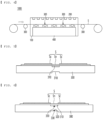
- FIG. 1 is a front view schematically showing the structure of a conventional electrode sheet drying apparatus
- FIG. 2 is a view showing the state of a non-coated portion (a) before and (b) after an electrode sheet is introduced into a chamber using the conventional electrode sheet drying apparatus.
- the conventional electrode sheet drying apparatus includes a chamber 11 having an empty interior, a heating means 12, and a guide roll 13, and an electrode sheet 20 is dried while passing through the conventional electrode sheet drying apparatus.
- the conventional electrode sheet drying apparatus has a merit in that it is possible to uniformly dry the electrode sheet 20. Since the entirety of the electrode sheet 20 is heated, however, thermal wrinkles are generated in a non-coated portion, i.e. a portion which has no active material applied thereto and from which an electrode current collector is exposed, as shown in (b) of FIG. 2 .
- Patent Document 1 discloses an electrode drying apparatus including an air conditioner configured to cool air outside the vicinity of an outlet of a chamber, through which an electrode sheet is discharged, and a cool air discharge nozzle configured to discharge cooled air to a non-coated portion, thereby inhibiting occurrence of such thermal wrinkles.
- Patent Document 1 has an advantage in that cool air is supplied to the non-coated portion, in which thermal wrinkles have already been generated in the high-temperature chamber, and therefore it is possible to more rapidly cool the non-coated portion than when natural cooling is performed outside the chamber, but has a problem in that it is not possible to fundamentally inhibit the occurrence of thermal wrinkles.
- Patent Document 1 Korean Registered Patent Publication No. 1810146
- the present invention has been made in view of the above problems, and it is an object of the present invention to provide an electrode sheet drying apparatus capable of preventing the occurrence of a thermal wrinkle phenomenon in a non-coated portion when an electrode sheet is dried.
- An electrode sheet drying apparatus for drying an electrode sheet (S) including a pair of coated portions (Sc) each having an electrode active material applied to one surface of a metal foil and a non-coated portion (Sn) located between the pair of coated portions (Sc), the non-coated portion having no electrode active material applied thereto, the electrode sheet drying apparatus including a chamber (100) configured to dry the electrode sheet (S) therein, the chamber having a rectangular structure, a heating means (200) provided at an upper part of the chamber (100), the heating means being configured to adjust the temperature in the chamber (100) to a temperature necessary to dry the electrode sheet (S), and at least one guide roll (300) configured to guide movement of the electrode sheet (S) in the chamber (100) and to maintain a tension of the electrode sheet (S), the apparatus being configured such that a part of the electrode sheet (S) is moved in a state of being spaced apart from the guide roll (300) by a predetermined distance.
- the guide roll (300) may be cylindrical and has a first concave recess (310) having a predetermined depth and width along a circumferential surface thereof.
- the first concave recess (310) may be located in the middle of the guide roll (300) in a longitudinal direction thereof.
- the apparatus is configured such that the non-coated portion (Sn) may be located above and spaced apart from the first concave recess (310) .
- the apparatus is configured such that the non-coated portion (Sn) and the interface between the coated portion (Sc) and the non-coated portion (Sn) may be located above the first concave recess (310) .
- a second concave recess (320) having a predetermined depth and width may be further provided in the first concave recess (310).
- a cooling pipe (330) disposed and extending in a direction perpendicular to the central axis of the guide roll (300) may be located at the second concave recess (320).
- the apparatus is configured such that the non-coated portion (Sn) may be spaced apart from the cooling pipe (330).
- opposite ends of the cooling pipe (330) may be located outside of the chamber (100) .
- the heating means (200) may be any one of: an infrared lamp, a heating coil, or a fan heater.
- An electrode sheet drying apparatus capable of preventing thermal wrinkles in a non-coated portion has a merit in that a concave recess is formed in a guide roll, whereby a non-coated portion of an electrode sheet is spaced apart from the guide roll by a predetermined distance, and therefore it is possible to reduce the occurrence of thermal wrinkles in the non-coated portion.
- the electrode sheet drying apparatus capable of preventing the thermal wrinkles in the non-coated portion according to the present invention has an advantage in that a cooling means is provided under the non-coated portion, whereby it is possible to minimize the occurrence of thermal wrinkles in the non-coated portion during a drying process.
- FIG. 3 is a perspective view schematically showing the structure of an electrode sheet drying apparatus according to an embodiment of the present invention
- FIG. 4 is a front view schematically showing the structure of the electrode sheet drying apparatus according to the embodiment of the present invention
- FIG. 5 is a sectional view taken along line B-B' of FIG. 3 , illustrating the structure of a guide roll.
- the electrode sheet drying apparatus 1000 which is an apparatus for continuously drying a long sheet type electrode, i.e., an electrode sheet S, includes a chamber 100, a heating means 200, a guide roll 300, and a cooling means 400.
- the electrode sheet S which is to be dried, is constituted by a coated portion Sc having an electrode active material applied to one surface of metal foil and a non-coated portion Sn having no electrode active material applied thereto.
- a pair of coated portions Sc spaced apart from each other by a predetermined distance may be provided.
- the non-coated portion Sn is located between the pair of coated portions Sc.
- the coated portion Sc is shown as being formed on only one surface of the metal foil in the drawings, it is obvious that the coated portion Sc may be provided at each of opposite surfaces of the metal foil.
- the electrode active material is classified as a positive electrode active material or a negative electrode active material, and a conductive agent and a binder is added to the electrode active material to manufacture a slurry, which is applied to the surface of the metal foil.
- the conductive agent is generally added so that the conductive agent accounts for 1 to 30 weight% based on the total weight of a mixture including the positive electrode active material.
- the conductive agent is not particularly restricted as long as the conductive agent exhibits high conductivity without inducing any chemical change in a battery to which the conductive agent is applied.
- graphite such as natural graphite or artificial graphite
- carbon black such as carbon black, acetylene black, Ketjen black, channel black, furnace black, lamp black, or thermal black
- conductive fiber such as carbon fiber or metallic fiber
- metallic powder such as carbon fluoride powder, aluminum powder, or nickel powder
- conductive whisker such as zinc oxide or potassium titanate
- a conductive metal oxide such as titanium oxide
- a conductive material such as a polyphenylene derivative
- the binder is a component assisting in binding between the active material and the conductive agent and in binding with a current collector.
- the binder is generally added in an amount of 1 to 30 weight% based on the total weight of the mixture including the positive electrode active material.
- the binder there may be used polyvinylidene fluoride, polyvinyl alcohol, carboxymethylcellulose (CMC), starch, hydroxypropylcellulose, regenerated cellulose, polyvinyl pyrrolidone, tetrafluoroethylene, polyethylene, polypropylene, ethylenepropylene-diene terpolymer (EPDM), sulfonated EPDM, styrene butadiene rubber, fluoro rubber, and various copolymers.
- the negative electrode active material for example, there may be used carbon, such as a non-graphitizing carbon or a graphite-based carbon; a metal composite oxide, such as Li x Fe 2 O 3 (0 ⁇ x ⁇ 1), Li x WO 2 (0 ⁇ x ⁇ 1), Sn x Me 1-x Me' y O z (Me: Mn, Fe, Pb, Ge; Me' : Al, B, P, Si, Group 1, 2, and 3 elements of the periodic table, halogen; 0 ⁇ x ⁇ 1; 1 ⁇ y ⁇ 3; 1 ⁇ z ⁇ 8); lithium metal; a lithium alloy; a silicon-based alloy; a tin-based alloy; a metal oxide, such as SnO, SnO 2 , PbO, PbO 2 , Pb 2 O 3 , Pb 3 O 4 , Sb 2 O 3 , Sb 2 O 4 , Sb 2 O 5 , GeO, GeO 2 , Bi 2 O 3 , Bi 2 O 4 , or Bi 2
- the conductive agent and the binder described above may be optionally further included in the negative electrode active material.
- the chamber 100 which is configured to receive the electrode sheet S constituted by the coated portion Sc having the electrode active material applied thereto and the non-coated portion Sn having no electrode active material applied thereto in order to dry the coated portion Sc, may have a rectangular structure.
- the interior of the chamber is empty, a part of each of a front surface and a rear surface of the chamber is open such that the electrode sheet S can be continuously supplied and discharged, and the other surfaces, i.e. a lower surface, an upper surface, and a pair of side surfaces, of the chamber are closed.
- the heating means 200 is configured to maintain the temperature in the chamber 100 within a predetermined temperature range. Specifically, the heating means maintains the temperature in the chamber 100 within a predetermined temperature range such that the coated portion Sc of the electrode sheet S can be dried. Although the heating means is shown as being provided in the chamber 100 at an upper part thereof in the drawings, it is obvious that the heating means may be further provided at a side of the chamber.
- thermoelectric heating means 200 capable of heating the interior of the chamber 100 or the electrode sheet S and maintaining uniform temperature, such as heat, hot air, or a light source, may be used as the heating means 200 that performs the above function.
- heat, hot air, or a light source may be used as the heating means 200 that performs the above function.
- an infrared lamp, a heating coil, and a fan heater may be used alone or in a combination of two or more thereof.
- the guide roll 300 is located in the chamber 100 including the vicinities of an inlet and an outlet of the chamber 100 in order to guide movement of the electrode sheet S and to maintain the electrode sheet S dried in the chamber 100 at uniform tension without drooping.
- the guide roll 300 supports the entirety of the electrode sheet S so as to have uniform tension without distinguishing between the coated portion Sc and the non-coated portion Sn of the electrode sheet S.
- the non-coated portion Sn having no active material applied thereto of the electrode sheet S is stretched to a relatively great extent in the chamber 100 heated to a predetermined temperature, whereby wrinkles are formed in the non-coated portion.
- the guide roll 300 located in the chamber 100 of the present invention is cylindrical, and a first concave recess 310 having a predetermined depth and width is provided along a circumferential surface of the guide roll, whereby it is possible to minimize formation of wrinkles in the non-coated portion Sn.
- the temperature in the chamber 100 is maintained within a range of about 100 to 200°C such that the coated portion Sc can be dried, and the guide roll 300 retains high heat therein, since the guide roll is made of a heat-resistant material, such as metal or ceramic.
- the non-coated portion Sn having no active material applied thereto comes into tight contact with the guide roll 300, the non-coated portion is more easily stretched than the coated portion Sc, whereby wrinkles are generated in the non-coated portion.
- the first concave recess 310 is located in the middle of the guide roll 300 in a longitudinal direction thereof, whereby the coated portion Sc is transferred in a state of being in tight contact with the guide roll, whereas the non-coated portion Sn, in which wrinkles may be easily formed, is spaced apart from the guide roll.
- the non-coated portion Sn in which wrinkles may be easily formed, is spaced apart from the guide roll.
- the interface between the coated portion Sc and the non-coated portion Sn may be located above the non-coated portion Sn.
- the depth of the first concave recess 310 is not particularly restricted, it is preferable for the depth of the first concave recess to be set to such an extent that the non-coated portion Sn does not contact the first concave recess.
- FIG. 6 shows a modification of the guide roll.
- a second concave recess 320 having a predetermined depth and width may be further provided in the first concave recess 310.
- a cooling pipe 330 disposed in a direction perpendicular to the central axis of the guide roll 300 is located at the second concave recess 320.
- the non-coated portion Sn is located vertically above the first concave recess 310 of the guide roll 300, whereby the non-coated portion does not directly contact the guide roll, there is a possibility of wrinkles being formed in the non-coated portion since the temperature in the chamber 100 is relatively high.
- a low-temperature refrigerant circulates along the cooling pipe 330 in the second concave recess 320, whereby it is possible to inhibit an increase in temperature of the non-coated portion Sn.
- the cooling pipe 330 and the non-coated portion Sn are slightly spaced apart from each other, the cooling pipe 330 extends long along the second concave recess 320 of the guide roll 300, and opposite ends of the cooling pipe are connected to a refrigerant circulation and supply device (not shown) located outside the chamber 100.
- FIG. 7 is a sectional view taken along line A-A' of FIG. 3 . A description will be given with reference to FIGs. 3 , 4 , and 7 .
- the electrode sheet drying apparatus 1000 further includes a cooling means 400 configured to reliably lower the temperature of the non-coated portion Sn in order to minimize stretching of the non-coated portion.
- the cooling means 400 may be provided in the vicinity of a bottom of the electrode sheet drying apparatus 1000 so as to face a rear surface of the electrode sheet S at which no coating portion Sc is formed, and the cooling means supplies cold air toward the non-coated portion Sn.
- cooling means 400 may be used as the cooling means 400, and the cooling means may be manufactured using an air cooling device or a nozzle configured to spray cooled air to a desired position so as to have a desired structure.
- the cooling means 400 may be configured to continuously supply cold air to the non-coated portion from the vicinity of an inner inlet of the chamber 100 to the vicinity of an outlet of the chamber 100, i.e. from the point in time at which the electrode sheet S enters the chamber 100 to the point in time at which the electrode sheet is discharged from the chamber 100, in order to cool the non-coated portion.
- cooling means 400 is a nozzle configured to spray cold air
- a height adjustment means configured to adjust the height of the nozzle
- a separate cooling air adjustment means configured to adjust the temperature and amount of air to be sprayed may be further provided.
- thermometer configured to measure the temperature of the non-coated portion Sn, such as a non-contact type infrared thermometer.
- the binder included in the active material is a component assisting in binding between the active material and the conductive agent and in binding with the metal foil.
- the amount of the binder remaining on the surface of the foil is reduced, whereby defects (an electrode deintercalation phenomenon, etc.) may occur due to a reduction in interfacial adhesive force between the active material and the metal foil.
- cold air is supplied to the non-coated portion Sn using the cooling means 400, whereby the temperature of the entire metal foil as well as the non-coated portion Sn may be reduced, compared to a conventional apparatus having no cooling means 400, and therefore there is also a merit in that it is possible to inhibit the migration phenomenon.
- the electrode sheet drying apparatus 1000 may further include a humidity adjustment unit configured to adjust the humidity in the chamber 100, a temperature sensor configured to measure the temperature in the chamber 100, and a controller configured to control the heating means 200.
- the drying method according to the present invention includes a) a step of introducing the electrode sheet S into the chamber 100 and heating and drying the electrode sheet S and b) a step of cooling the non-coated portion Sn of the electrode sheet S.
- step b) is a step of continuously supplying cold air to the non-coated portion Sn under the electrode sheet S until drying of the electrode sheet S is completed after drying of the electrode sheet is started in order to maintain the temperature of the non-coated portion Sn at a predetermined temperature or lower.
- step a) and step b) may be simultaneously performed.
- simultaneous performance means that cold air starts to be supplied to the non-coated portion Sn from almost the moment the electrode sheet S enters the chamber 100.
- the battery module or the battery pack may be used as a power supply source for various kinds of devices.
Landscapes
- Engineering & Computer Science (AREA)
- General Engineering & Computer Science (AREA)
- Mechanical Engineering (AREA)
- Textile Engineering (AREA)
- Chemical & Material Sciences (AREA)
- Chemical Kinetics & Catalysis (AREA)
- General Chemical & Material Sciences (AREA)
- Electrochemistry (AREA)
- Manufacturing & Machinery (AREA)
- Life Sciences & Earth Sciences (AREA)
- Microbiology (AREA)
- Combustion & Propulsion (AREA)
- Materials Engineering (AREA)
- Battery Electrode And Active Subsutance (AREA)
Abstract
Description
- This application claims the benefit of priority to
Korean Patent Application No. 2021-0153675 filed on November 10, 2021 - The present invention relates to an electrode sheet drying apparatus capable of preventing thermal wrinkles in a non-coated portion, and more particularly to an electrode sheet drying apparatus capable of preventing thermal wrinkles in a non-coated portion configured such that a guide roll and the non-coated portion are spaced apart from each other by a predetermined distance in order to prevent occurrence of a thermal wrinkle phenomenon in the non-coated portion when the electrode sheet is dried and a means configured to selectively cool the non-coated portion is provided.
- With technological development of mobile devices, such as smartphones, laptop computers, and digital cameras, and an increase in demand therefor, research on secondary batteries, which are capable of being charged and discharged, has been actively conducted. In addition, secondary batteries, which are energy sources substituting for fossil fuels causing air pollution, have been applied to an electric vehicle (EV), a hybrid electric vehicle (HEV), a plug-in hybrid electric vehicle (P-HEV), and an energy storage system (ESS) .
- There are a lithium ion battery, a lithium polymer battery, a nickel cadmium battery, a nickel hydride battery, and a nickel zinc battery as secondary batteries that are widely used at present.
- In general, such a secondary battery is configured such that an electrode assembly and an electrolytic solution are received in a battery case.
- Here, the electrode assembly may generally be a jelly-roll type assembly, which is configured to have a structure in which a long sheet type positive electrode and a long sheet type negative electrode are wound in the state in which a separator is interposed therebetween, a stacked type assembly, which is configured to have a structure in which a rectangular positive electrode and a rectangular negative electrode are stacked in the state in which a separator is interposed therebetween, a stacked and folded type assembly, which is configured to have a structure in which unit cells are wound using a long separation film, or a laminated and stacked type assembly, which is configured to have a structure in which battery cells are stacked in the state in which a separator is interposed therebetween and are then attached to each other.
- In addition, an electrolyte may be replaced by a solid electrolyte or a gel type quasi-solid electrolyte obtained by adding an additive to a solid electrolyte, the gel type quasi-solid electrolyte having an intermediate phase between a liquid and a solid, in addition to a liquid electrolyte, which is commonly used.
- The electrode assembly is received in the battery case, and the secondary battery may be classified as a cylindrical battery having the electrode assembly mounted in a cylindrical metal can, a prismatic battery having the electrode assembly mounted in a prismatic metal can, or a pouch-shaped battery having the electrode assembly mounted in a pouch-shaped case made of an aluminum laminate sheet based on the kind of the battery case.
- Meanwhile, a method of manufacturing the electrode of the secondary battery includes a process of applying a slurry manufactured by dispersing an active material, a conductive agent, and a binder in a solvent to an electrode current collector and drying the slurry.
- At this time, the electrode may be dried using a method of introducing a sheet type electrode into a drying apparatus in a state of being wound around a roll and drying the electrode. In this case, however, as the drying process is performed in an overlapping state, there is a difference in dryness between the inside and the outside of the electrode.
-
FIG. 1 is a front view schematically showing the structure of a conventional electrode sheet drying apparatus, andFIG. 2 is a view showing the state of a non-coated portion (a) before and (b) after an electrode sheet is introduced into a chamber using the conventional electrode sheet drying apparatus. - As shown in
FIG. 1 , the conventional electrode sheet drying apparatus includes achamber 11 having an empty interior, a heating means 12, and aguide roll 13, and anelectrode sheet 20 is dried while passing through the conventional electrode sheet drying apparatus. - The conventional electrode sheet drying apparatus has a merit in that it is possible to uniformly dry the
electrode sheet 20. Since the entirety of theelectrode sheet 20 is heated, however, thermal wrinkles are generated in a non-coated portion, i.e. a portion which has no active material applied thereto and from which an electrode current collector is exposed, as shown in (b) ofFIG. 2 . - The reason that such thermal wrinkles are generated is that, when the electrode sheet enters the chamber, which is maintained at a relatively high temperature, rigidity of the electrode current collector made of metal foil is reduced. In particular, the temperature of the non-coated portion, which has no active material, becomes higher than the temperature of the region having the active material applied thereto. As a result, wrinkles are intensively generated in the non-coated portion.
- Meanwhile, Patent Document 1 discloses an electrode drying apparatus including an air conditioner configured to cool air outside the vicinity of an outlet of a chamber, through which an electrode sheet is discharged, and a cool air discharge nozzle configured to discharge cooled air to a non-coated portion, thereby inhibiting occurrence of such thermal wrinkles.
- The apparatus of Patent Document 1 has an advantage in that cool air is supplied to the non-coated portion, in which thermal wrinkles have already been generated in the high-temperature chamber, and therefore it is possible to more rapidly cool the non-coated portion than when natural cooling is performed outside the chamber, but has a problem in that it is not possible to fundamentally inhibit the occurrence of thermal wrinkles.
- (Patent Document 1)
Korean Registered Patent Publication No. 1810146 - The present invention has been made in view of the above problems, and it is an object of the present invention to provide an electrode sheet drying apparatus capable of preventing the occurrence of a thermal wrinkle phenomenon in a non-coated portion when an electrode sheet is dried.
- An electrode sheet drying apparatus according to the present invention to accomplish the above object is an electrode sheet drying apparatus for drying an electrode sheet (S) including a pair of coated portions (Sc) each having an electrode active material applied to one surface of a metal foil and a non-coated portion (Sn) located between the pair of coated portions (Sc), the non-coated portion having no electrode active material applied thereto, the electrode sheet drying apparatus including a chamber (100) configured to dry the electrode sheet (S) therein, the chamber having a rectangular structure, a heating means (200) provided at an upper part of the chamber (100), the heating means being configured to adjust the temperature in the chamber (100) to a temperature necessary to dry the electrode sheet (S), and at least one guide roll (300) configured to guide movement of the electrode sheet (S) in the chamber (100) and to maintain a tension of the electrode sheet (S), the apparatus being configured such that a part of the electrode sheet (S) is moved in a state of being spaced apart from the guide roll (300) by a predetermined distance.
- Also, in the electrode sheet drying apparatus according to the present invention, the guide roll (300) may be cylindrical and has a first concave recess (310) having a predetermined depth and width along a circumferential surface thereof.
- Also, in the electrode sheet drying apparatus according to the present invention, the first concave recess (310) may be located in the middle of the guide roll (300) in a longitudinal direction thereof.
- Also, in the electrode sheet drying apparatus according to the present invention, the apparatus is configured such that the non-coated portion (Sn) may be located above and spaced apart from the first concave recess (310) .
- Also, in the electrode sheet drying apparatus according to the present invention, the apparatus is configured such that the non-coated portion (Sn) and the interface between the coated portion (Sc) and the non-coated portion (Sn) may be located above the first concave recess (310) .
- Also, in the electrode sheet drying apparatus according to the present invention, a second concave recess (320) having a predetermined depth and width may be further provided in the first concave recess (310).
- Also, in the electrode sheet drying apparatus according to the present invention, a cooling pipe (330) disposed and extending in a direction perpendicular to the central axis of the guide roll (300) may be located at the second concave recess (320).
- Also, in the electrode sheet drying apparatus according to the present invention, the apparatus is configured such that the non-coated portion (Sn) may be spaced apart from the cooling pipe (330).
- Also, in the electrode sheet drying apparatus according to the present invention, opposite ends of the cooling pipe (330) may be located outside of the chamber (100) .
- Also, in the electrode sheet drying apparatus according to the present invention, the heating means (200) may be any one of: an infrared lamp, a heating coil, or a fan heater.
- An electrode sheet drying apparatus capable of preventing thermal wrinkles in a non-coated portion according to the present invention has a merit in that a concave recess is formed in a guide roll, whereby a non-coated portion of an electrode sheet is spaced apart from the guide roll by a predetermined distance, and therefore it is possible to reduce the occurrence of thermal wrinkles in the non-coated portion.
- In addition, the electrode sheet drying apparatus capable of preventing the thermal wrinkles in the non-coated portion according to the present invention has an advantage in that a cooling means is provided under the non-coated portion, whereby it is possible to minimize the occurrence of thermal wrinkles in the non-coated portion during a drying process.
-
-
FIG. 1 is a front view schematically showing the structure of a conventional electrode sheet drying apparatus. -
FIG. 2 is a view showing the state of a non-coated portion (a) before and (b) after an electrode sheet is introduced into a chamber using the conventional electrode sheet drying apparatus. -
FIG. 3 is a perspective view schematically showing the structure of an electrode sheet drying apparatus according to an embodiment of the present invention. -
FIG. 4 is a front view schematically showing the structure of the electrode sheet drying apparatus according to the embodiment of the present invention. -
FIG. 5 is a sectional view taken along line B-B' ofFIG. 3 , illustrating the structure of a guide roll. -
FIG. 6 is a view showing a modification of the guide roll. -
FIG. 7 is a sectional view taken along line A-A' ofFIG. 3 . - In the present application, it should be understood that the terms "comprises," "has," "includes," etc. specify the presence of stated features, numbers, steps, operations, elements, components, or combinations thereof, but do not preclude the presence or addition of one or more other features, numbers, steps, operations, elements, components, or combinations thereof.
- In addition, the same reference numbers will be used throughout the drawings to refer to parts that perform similar functions or operations. In the case in which one part is said to be connected to another part in the specification, not only may the one part be directly connected to the other part, but also, the one part may be indirectly connected to the other part via a further part. In addition, that a certain element is included does not mean that other elements are excluded, but means that such elements may be further included unless mentioned otherwise.
- Hereinafter, an electrode sheet drying apparatus according to the present invention will be described with reference to the accompanying drawings.
-
FIG. 3 is a perspective view schematically showing the structure of an electrode sheet drying apparatus according to an embodiment of the present invention,FIG. 4 is a front view schematically showing the structure of the electrode sheet drying apparatus according to the embodiment of the present invention, andFIG. 5 is a sectional view taken along line B-B' ofFIG. 3 , illustrating the structure of a guide roll. - When describing the electrode
sheet drying apparatus 1000 according to the present invention with reference toFIGs. 3 to 5 , the electrodesheet drying apparatus 1000, which is an apparatus for continuously drying a long sheet type electrode, i.e., an electrode sheet S, includes achamber 100, a heating means 200, aguide roll 300, and a cooling means 400. - First, the electrode sheet S, which is to be dried, is constituted by a coated portion Sc having an electrode active material applied to one surface of metal foil and a non-coated portion Sn having no electrode active material applied thereto.
- Here, a pair of coated portions Sc spaced apart from each other by a predetermined distance may be provided. At this time, the non-coated portion Sn is located between the pair of coated portions Sc. Although the coated portion Sc is shown as being formed on only one surface of the metal foil in the drawings, it is obvious that the coated portion Sc may be provided at each of opposite surfaces of the metal foil.
- Meanwhile, the electrode active material is classified as a positive electrode active material or a negative electrode active material, and a conductive agent and a binder is added to the electrode active material to manufacture a slurry, which is applied to the surface of the metal foil.
- The positive electrode active material may be constituted, for example, by a layered compound, such as a lithium cobalt oxide (LiCoO2) or a lithium nickel oxide (LiNiO2), or a compound substituted with one or more transition metals; a lithium manganese oxide represented by the chemical formula Li1+xMn2-xO4 (where x = 0 to 0.33) or a lithium manganese oxide, such as LiMnO3, LiMn2O3, or LiMnO2; a lithium copper oxide (Li2CuO2); a vanadium oxide, such as LiV3O8, LiFe3O4, V2O5, or Cu2V2O7; a Ni-sited lithium nickel oxide represented by the chemical formula LiNi1-xMxO2 (where M = Co, Mn, Al, Cu, Fe, Mg, B, or Ga, and x = 0.01 to 0.3); a lithium manganese composite oxide represented by the chemical formula LiMn2-xMxO2 (where M = Co, Ni, Fe, Cr, Zn, or Ta, and x = 0.01 to 0.1) or the chemical formula Li2Mn3MO8 (where M = Fe, Co, Ni, Cu, or Zn); LiMn2O4 in which a portion of Li in the chemical formula is replaced by alkaline earth metal ions; a disulfide compound; or Fe2(MoO4)3. However, the present invention is not limited thereto.
- The conductive agent is generally added so that the conductive agent accounts for 1 to 30 weight% based on the total weight of a mixture including the positive electrode active material.
- The conductive agent is not particularly restricted as long as the conductive agent exhibits high conductivity without inducing any chemical change in a battery to which the conductive agent is applied. For example, graphite, such as natural graphite or artificial graphite; carbon black, such as carbon black, acetylene black, Ketjen black, channel black, furnace black, lamp black, or thermal black; conductive fiber, such as carbon fiber or metallic fiber; metallic powder, such as carbon fluoride powder, aluminum powder, or nickel powder; conductive whisker, such as zinc oxide or potassium titanate; a conductive metal oxide, such as titanium oxide; or a conductive material, such as a polyphenylene derivative, may be used as the conductive agent.
- The binder is a component assisting in binding between the active material and the conductive agent and in binding with a current collector. The binder is generally added in an amount of 1 to 30 weight% based on the total weight of the mixture including the positive electrode active material. As examples of the binder, there may be used polyvinylidene fluoride, polyvinyl alcohol, carboxymethylcellulose (CMC), starch, hydroxypropylcellulose, regenerated cellulose, polyvinyl pyrrolidone, tetrafluoroethylene, polyethylene, polypropylene, ethylenepropylene-diene terpolymer (EPDM), sulfonated EPDM, styrene butadiene rubber, fluoro rubber, and various copolymers.
- In addition, as the negative electrode active material, for example, there may be used carbon, such as a non-graphitizing carbon or a graphite-based carbon; a metal composite oxide, such as LixFe2O3 (0≤x≤1), LixWO2 (0≤x≤1), SnxMe1-xMe'yOz (Me: Mn, Fe, Pb, Ge; Me' : Al, B, P, Si, Group 1, 2, and 3 elements of the periodic table, halogen; 0<x≤1; 1≤y≤3; 1≤z≤8); lithium metal; a lithium alloy; a silicon-based alloy; a tin-based alloy; a metal oxide, such as SnO, SnO2, PbO, PbO2, Pb2O3, Pb3O4, Sb2O3, Sb2O4, Sb2O5, GeO, GeO2, Bi2O3, Bi2O4, or Bi2O5; a conductive polymer, such as polyacetylene; a Li-Co-Ni-based material; or a Si-based material, such as Si, SiO, SiO2, or a mixture thereof. However, the present invention is not limited thereto.
- In addition, the conductive agent and the binder described above may be optionally further included in the negative electrode active material.
- The
chamber 100, which is configured to receive the electrode sheet S constituted by the coated portion Sc having the electrode active material applied thereto and the non-coated portion Sn having no electrode active material applied thereto in order to dry the coated portion Sc, may have a rectangular structure. - Specifically, the interior of the chamber is empty, a part of each of a front surface and a rear surface of the chamber is open such that the electrode sheet S can be continuously supplied and discharged, and the other surfaces, i.e. a lower surface, an upper surface, and a pair of side surfaces, of the chamber are closed.
- Consequently, it is possible to maintain the temperature in the chamber within a predetermined temperature range and to prevent introduction of external foreign matter into the chamber.
- The heating means 200 is configured to maintain the temperature in the
chamber 100 within a predetermined temperature range. Specifically, the heating means maintains the temperature in thechamber 100 within a predetermined temperature range such that the coated portion Sc of the electrode sheet S can be dried. Although the heating means is shown as being provided in thechamber 100 at an upper part thereof in the drawings, it is obvious that the heating means may be further provided at a side of the chamber. - Various known heat sources capable of heating the interior of the
chamber 100 or the electrode sheet S and maintaining uniform temperature, such as heat, hot air, or a light source, may be used as the heating means 200 that performs the above function. For example, an infrared lamp, a heating coil, and a fan heater may be used alone or in a combination of two or more thereof. - Next, the
guide roll 300 is located in thechamber 100 including the vicinities of an inlet and an outlet of thechamber 100 in order to guide movement of the electrode sheet S and to maintain the electrode sheet S dried in thechamber 100 at uniform tension without drooping. - As previously described, the
guide roll 300 supports the entirety of the electrode sheet S so as to have uniform tension without distinguishing between the coated portion Sc and the non-coated portion Sn of the electrode sheet S. As a result, the non-coated portion Sn having no active material applied thereto of the electrode sheet S is stretched to a relatively great extent in thechamber 100 heated to a predetermined temperature, whereby wrinkles are formed in the non-coated portion. - However, the
guide roll 300 located in thechamber 100 of the present invention is cylindrical, and a firstconcave recess 310 having a predetermined depth and width is provided along a circumferential surface of the guide roll, whereby it is possible to minimize formation of wrinkles in the non-coated portion Sn. - Specifically, the temperature in the
chamber 100 is maintained within a range of about 100 to 200°C such that the coated portion Sc can be dried, and theguide roll 300 retains high heat therein, since the guide roll is made of a heat-resistant material, such as metal or ceramic. When the non-coated portion Sn having no active material applied thereto comes into tight contact with theguide roll 300, the non-coated portion is more easily stretched than the coated portion Sc, whereby wrinkles are generated in the non-coated portion. - In the present invention, however, the first
concave recess 310 is located in the middle of theguide roll 300 in a longitudinal direction thereof, whereby the coated portion Sc is transferred in a state of being in tight contact with the guide roll, whereas the non-coated portion Sn, in which wrinkles may be easily formed, is spaced apart from the guide roll. As a result, it is possible to reduce transfer of hot heat of theguide roll 300 to the non-coated portion Sn, and therefore it is possible to reduce generation of wrinkles in the non-coated portion Sn. - Here, although it is most preferable for the entire region of the non-coated portion Sn to be located above the first
concave recess 310 such that the non-coated portion does not come into tight contact with theguide roll 300, the interface between the coated portion Sc and the non-coated portion Sn may be located above the non-coated portion Sn. - In addition, although the depth of the first
concave recess 310 is not particularly restricted, it is preferable for the depth of the first concave recess to be set to such an extent that the non-coated portion Sn does not contact the first concave recess. -
FIG. 6 shows a modification of the guide roll. As shown inFIG. 6 , in the modification of theguide roll 300, a secondconcave recess 320 having a predetermined depth and width may be further provided in the firstconcave recess 310. At this time, acooling pipe 330 disposed in a direction perpendicular to the central axis of theguide roll 300 is located at the secondconcave recess 320. - Although the non-coated portion Sn is located vertically above the first
concave recess 310 of theguide roll 300, whereby the non-coated portion does not directly contact the guide roll, there is a possibility of wrinkles being formed in the non-coated portion since the temperature in thechamber 100 is relatively high. - In the modification, however, a low-temperature refrigerant circulates along the
cooling pipe 330 in the secondconcave recess 320, whereby it is possible to inhibit an increase in temperature of the non-coated portion Sn. - Here, the
cooling pipe 330 and the non-coated portion Sn are slightly spaced apart from each other, thecooling pipe 330 extends long along the secondconcave recess 320 of theguide roll 300, and opposite ends of the cooling pipe are connected to a refrigerant circulation and supply device (not shown) located outside thechamber 100. -
FIG. 7 is a sectional view taken along line A-A' ofFIG. 3 . A description will be given with reference toFIGs. 3 ,4 , and7 . - In addition, the electrode
sheet drying apparatus 1000 according to the present invention further includes a cooling means 400 configured to reliably lower the temperature of the non-coated portion Sn in order to minimize stretching of the non-coated portion. - Specifically, the cooling means 400 may be provided in the vicinity of a bottom of the electrode
sheet drying apparatus 1000 so as to face a rear surface of the electrode sheet S at which no coating portion Sc is formed, and the cooling means supplies cold air toward the non-coated portion Sn. - Various known cooling means may be used as the cooling means 400, and the cooling means may be manufactured using an air cooling device or a nozzle configured to spray cooled air to a desired position so as to have a desired structure.
- In addition, the cooling means 400 may be configured to continuously supply cold air to the non-coated portion from the vicinity of an inner inlet of the
chamber 100 to the vicinity of an outlet of thechamber 100, i.e. from the point in time at which the electrode sheet S enters thechamber 100 to the point in time at which the electrode sheet is discharged from thechamber 100, in order to cool the non-coated portion. - In addition, when the cooling means 400 is a nozzle configured to spray cold air, a height adjustment means configured to adjust the height of the nozzle may be provided, and a separate cooling air adjustment means configured to adjust the temperature and amount of air to be sprayed may be further provided.
- Furthermore, it is also possible to control the cooling means 400 while continuously measuring the temperature of the non-coated portion Sn through a thermometer configured to measure the temperature of the non-coated portion Sn, such as a non-contact type infrared thermometer.
- When the temperature of the non-coated portion Sn is lowered to a predetermined temperature range, as described above, it is possible to reduce stretching locally generated in the non-coated portion Sn and to inhibit formation of wrinkles in the non-coated portion.
- Meanwhile, as described above, the binder included in the active material is a component assisting in binding between the active material and the conductive agent and in binding with the metal foil.
- When the metal foil is heated during a drying process, whereby the temperature of the metal foil is increased, however, a phenomenon in which the binder distributed on the contact surface with the metal foil migrates to the interior of the uppermost layer (outer surface) of the coated portion Sc, i.e. a migration phenomenon, may occur.
- When such a migration phenomenon occurs, the amount of the binder remaining on the surface of the foil is reduced, whereby defects (an electrode deintercalation phenomenon, etc.) may occur due to a reduction in interfacial adhesive force between the active material and the metal foil. In the present invention, cold air is supplied to the non-coated portion Sn using the cooling means 400, whereby the temperature of the entire metal foil as well as the non-coated portion Sn may be reduced, compared to a conventional apparatus having no cooling means 400, and therefore there is also a merit in that it is possible to inhibit the migration phenomenon.
- Meanwhile, although not shown in the drawings, the electrode
sheet drying apparatus 1000 may further include a humidity adjustment unit configured to adjust the humidity in thechamber 100, a temperature sensor configured to measure the temperature in thechamber 100, and a controller configured to control the heating means 200. - Hereinafter, a method of drying the electrode sheet S using the electrode
sheet drying apparatus 1000 according to the present invention will be described. - The drying method according to the present invention includes a) a step of introducing the electrode sheet S into the
chamber 100 and heating and drying the electrode sheet S and b) a step of cooling the non-coated portion Sn of the electrode sheet S. - Here, step b) is a step of continuously supplying cold air to the non-coated portion Sn under the electrode sheet S until drying of the electrode sheet S is completed after drying of the electrode sheet is started in order to maintain the temperature of the non-coated portion Sn at a predetermined temperature or lower.
- In addition, step a) and step b) may be simultaneously performed. Here, simultaneous performance means that cold air starts to be supplied to the non-coated portion Sn from almost the moment the electrode sheet S enters the
chamber 100. - It is possible to manufacture a battery cell including the electrode manufactured through the drying method, and it is possible to manufacture a battery module or a battery pack using the battery cell.
- The battery module or the battery pack may be used as a power supply source for various kinds of devices.
- Although the specific details of the present invention have been described in detail, those skilled in the art will appreciate that the detailed description thereof discloses only preferred embodiments of the present invention and thus does not limit the scope of the present invention. Accordingly, those skilled in the art will appreciate that various changes and modifications are possible, without departing from the category and the technical idea of the present invention, and it will be obvious that such changes and modifications fall within the scope of the appended claims.
-
- 1000:
- Electrode sheet drying apparatus
- 100:
- Chamber
- 200:
- Heating means
- 300:
- Guide roll
- 310:
- First concave recess
- 320:
- Second concave recess
- 330:
- Cooling pipe
- 400:
- Cooling means
- S:
- Electrode sheet
- Sc:
- Coated portion
- Sn:
- Non-coated portion
Claims (10)
- An electrode sheet drying apparatus for drying an electrode sheet comprising a pair of coated portions each having an electrode active material applied to one surface of a metal foil and a non-coated portion located between the pair of coated portions, the non-coated portion having no electrode active material applied thereto, the electrode sheet drying apparatus comprising:a chamber configured to dry the electrode sheet therein, the chamber having a rectangular structure;a heating means provided at an upper part of the chamber, the heating means being configured to adjust a temperature in the chamber to a temperature necessary to dry the electrode sheet; andat least one guide roll configured to guide movement of the electrode sheet in the chamber and to maintain a tension of the electrode sheet, the apparatus being configured such that a part of the electrode sheet is moved in a state of being spaced apart from the guide roll by a predetermined distance.
- The electrode sheet drying apparatus according to claim 1, wherein the guide roll is cylindrical and has a first concave recess having a predetermined depth and width along a circumferential surface thereof.
- The electrode sheet drying apparatus according to claim 2, wherein the first concave recess is located in a middle of the guide roll in a longitudinal direction thereof.
- The electrode sheet drying apparatus according to claim 3, wherein the apparatus is configured such that the non-coated portion is located above and spaced apart from the first concave recess.
- The electrode sheet drying apparatus according to claim 3, wherein the apparatus is configured such that the non-coated portion and an interface between the coated portion and the non-coated portion are located above the first concave recess.
- The electrode sheet drying apparatus according to claim 2, wherein a second concave recess having a predetermined depth and width is further provided in the first concave recess.
- The electrode sheet drying apparatus according to claim 6, wherein a cooling pipe disposed and extending in a direction perpendicular to a central axis of the guide roll is located at the second concave recess.
- The electrode sheet drying apparatus according to claim 7, wherein the apparatus is configured such that the non-coated portion is spaced apart from the cooling pipe.
- The electrode sheet drying apparatus according to claim 7, wherein opposite ends of the cooling pipe are located outside of the chamber.
- The electrode sheet drying apparatus according to claim 1, wherein the heating means is any one of: an infrared lamp, a heating coil, or a fan heater.
Applications Claiming Priority (2)
| Application Number | Priority Date | Filing Date | Title |
|---|---|---|---|
| KR1020210153675A KR102848553B1 (en) | 2021-11-10 | 2021-11-10 | Electrode drying device that can prevent thermal wrinkles in the non-coated portion |
| PCT/KR2022/016532 WO2023085654A1 (en) | 2021-11-10 | 2022-10-27 | Electrode sheet drying device capable of preventing thermal wrinkles in uncoated portion |
Publications (3)
| Publication Number | Publication Date |
|---|---|
| EP4258376A1 true EP4258376A1 (en) | 2023-10-11 |
| EP4258376A4 EP4258376A4 (en) | 2024-07-17 |
| EP4258376B1 EP4258376B1 (en) | 2026-03-25 |
Family
ID=86336389
Family Applications (1)
| Application Number | Title | Priority Date | Filing Date |
|---|---|---|---|
| EP22893077.2A Active EP4258376B1 (en) | 2021-11-10 | 2022-10-27 | Electrode sheet drying apparatus capable of preventing thermal wrinkles in non-coated portion |
Country Status (6)
| Country | Link |
|---|---|
| US (1) | US20240384931A1 (en) |
| EP (1) | EP4258376B1 (en) |
| JP (1) | JP7640135B2 (en) |
| KR (1) | KR102848553B1 (en) |
| CN (1) | CN116635683A (en) |
| WO (1) | WO2023085654A1 (en) |
Cited By (1)
| Publication number | Priority date | Publication date | Assignee | Title |
|---|---|---|---|---|
| JP2025121800A (en) * | 2024-02-07 | 2025-08-20 | トヨタ自動車株式会社 | Electrode manufacturing method and power storage device manufacturing method |
Families Citing this family (5)
| Publication number | Priority date | Publication date | Assignee | Title |
|---|---|---|---|---|
| KR102848553B1 (en) * | 2021-11-10 | 2025-08-21 | 주식회사 엘지에너지솔루션 | Electrode drying device that can prevent thermal wrinkles in the non-coated portion |
| KR102894472B1 (en) * | 2023-07-10 | 2025-12-03 | (주)피엔티 | Electrode Sheet for Secondary Battery veer-preventing Type Drying Chamber Device |
| JP2025033210A (en) * | 2023-08-29 | 2025-03-13 | トヨタ自動車株式会社 | Electrode manufacturing method |
| US12494471B2 (en) | 2023-12-08 | 2025-12-09 | Enovix Corporation | Mechanical stripping of sacrificial layer |
| KR20250174215A (en) | 2024-06-05 | 2025-12-12 | 주식회사 엘지에너지솔루션 | Electrode manufacturing method and electrode manufacturing equipment |
Family Cites Families (22)
| Publication number | Priority date | Publication date | Assignee | Title |
|---|---|---|---|---|
| JP3299429B2 (en) * | 1995-12-13 | 2002-07-08 | 松下電器産業株式会社 | Battery electrode drying equipment |
| JPH11102696A (en) * | 1997-09-26 | 1999-04-13 | Sony Corp | Electrode manufacturing apparatus and manufacturing method |
| JP2963443B1 (en) * | 1998-06-19 | 1999-10-18 | キヤノン販売株式会社 | Semiconductor device manufacturing equipment |
| JP3684941B2 (en) * | 1999-10-13 | 2005-08-17 | ソニーケミカル株式会社 | Coating film forming apparatus and coating film forming method |
| JP2001351616A (en) * | 2000-06-05 | 2001-12-21 | Toyota Motor Corp | Electrode manufacturing method |
| JP4929747B2 (en) * | 2005-03-28 | 2012-05-09 | コニカミノルタオプト株式会社 | Manufacturing method of optical film |
| CN101360965B (en) * | 2006-05-18 | 2010-12-22 | 富士胶片株式会社 | Method and apparatus for drying object to be dried |
| JP4985543B2 (en) * | 2008-05-22 | 2012-07-25 | トヨタ自動車株式会社 | Transport device |
| KR101175031B1 (en) * | 2010-12-30 | 2012-08-17 | 삼성에스디아이 주식회사 | Method of fabricating electrode plate and electrode plate fabricated by the same method |
| KR101181824B1 (en) * | 2011-03-17 | 2012-09-11 | 삼성에스디아이 주식회사 | Dryer for electrode substrate |
| WO2014039194A1 (en) * | 2012-09-07 | 2014-03-13 | Applied Materials, Inc. | Integrated processing of porous dielectric, polymer-coated substrates and epoxy within a multi-chamber vacuum system confirmation |
| US8756825B2 (en) * | 2012-10-11 | 2014-06-24 | Eastman Kodak Company | Removing moistening liquid using heating-liquid barrier |
| US9096079B2 (en) * | 2012-10-11 | 2015-08-04 | Eastman Kodak Company | Dryer impinging heating liquid onto moistened medium |
| WO2015058027A1 (en) * | 2013-10-17 | 2015-04-23 | Triglia Joseph P Jr | System and method of removing moisture from fibrous or porous materials using microwave radiation and rf energy |
| KR101810146B1 (en) | 2016-07-21 | 2017-12-19 | (주)피엔티 | Dryer used in manufacturing electrode of secondary battery |
| JP7200143B2 (en) * | 2017-06-20 | 2023-01-06 | コアシェル テクノロジーズ インコーポレイテッド | Methods, systems, and compositions for liquid deposition of thin films on surfaces of battery electrodes |
| US12048910B2 (en) * | 2018-07-11 | 2024-07-30 | Board Of Trustees Of Michigan State University | Vertically oriented plasma reactor |
| KR102206057B1 (en) * | 2018-11-20 | 2021-01-20 | 주식회사 엘지화학 | An electrode rolling apparatus having a heating unit for heating a non-coated portion and Manufacturing system for an electrode comprising the same |
| JP7239893B2 (en) * | 2019-12-11 | 2023-03-15 | 株式会社豊田自動織機 | Drying equipment for electrode materials |
| JP7667790B2 (en) * | 2020-09-30 | 2025-04-23 | パナソニックホールディングス株式会社 | Workpiece transport device |
| CN120479720A (en) * | 2021-07-30 | 2025-08-15 | 宁德时代新能源科技股份有限公司 | Coating apparatus |
| KR102848553B1 (en) * | 2021-11-10 | 2025-08-21 | 주식회사 엘지에너지솔루션 | Electrode drying device that can prevent thermal wrinkles in the non-coated portion |
-
2021
- 2021-11-10 KR KR1020210153675A patent/KR102848553B1/en active Active
-
2022
- 2022-10-27 CN CN202280008262.5A patent/CN116635683A/en active Pending
- 2022-10-27 EP EP22893077.2A patent/EP4258376B1/en active Active
- 2022-10-27 US US18/272,420 patent/US20240384931A1/en active Pending
- 2022-10-27 WO PCT/KR2022/016532 patent/WO2023085654A1/en not_active Ceased
- 2022-10-27 JP JP2023521784A patent/JP7640135B2/en active Active
Cited By (1)
| Publication number | Priority date | Publication date | Assignee | Title |
|---|---|---|---|---|
| JP2025121800A (en) * | 2024-02-07 | 2025-08-20 | トヨタ自動車株式会社 | Electrode manufacturing method and power storage device manufacturing method |
Also Published As
| Publication number | Publication date |
|---|---|
| JP2023553248A (en) | 2023-12-21 |
| EP4258376B1 (en) | 2026-03-25 |
| WO2023085654A1 (en) | 2023-05-19 |
| CN116635683A (en) | 2023-08-22 |
| EP4258376A4 (en) | 2024-07-17 |
| KR102848553B1 (en) | 2025-08-21 |
| KR20230067929A (en) | 2023-05-17 |
| US20240384931A1 (en) | 2024-11-21 |
| JP7640135B2 (en) | 2025-03-05 |
Similar Documents
| Publication | Publication Date | Title |
|---|---|---|
| EP4258376B1 (en) | Electrode sheet drying apparatus capable of preventing thermal wrinkles in non-coated portion | |
| US8460812B2 (en) | Lithium secondary battery | |
| US11322730B2 (en) | Positive electrode for nonaqeous electrolyte secondary battery and a nonaqueous electrolyte secondary battery | |
| CN114930178B (en) | Equipment and methods for measuring the capacity of individual battery cells | |
| EP4106041B1 (en) | Electrode drying system and electrode drying method | |
| EP2378595A2 (en) | High-power lithium secondary battery | |
| EP2899791A1 (en) | Electrode assembly and electrochemical device including same | |
| US10833313B2 (en) | Positive electrode for nonaqeous electrolyte secondary battery and a nonaqueous electrolyte secondary battery | |
| KR20160047690A (en) | Lamination Device Using High-frequency Induction Heating and Secondary Battery Manufactured Using the Same | |
| US12607403B2 (en) | Automatic electrode drying control system and automatic electrode drying control method | |
| US11870039B2 (en) | Electrode assembly and method for manufacturing the same | |
| JP7754572B2 (en) | Manufacturing method of curved secondary battery | |
| KR102914154B1 (en) | Electrode drying device that can prevent thermal wrinkles in the non-coated portion | |
| KR20240098990A (en) | Powder feeding device for dry electrode and dry electrode manufacturing system using same | |
| KR102875361B1 (en) | Manufacturing Method of Electrode Assembly and Electrode Assembly By Using The Same | |
| US11522169B2 (en) | Sulfide-based all-solid-state battery including surface heat-treated positive electrode active material and method of manufacturing the same | |
| KR102935848B1 (en) | Roll for Electrode drying including heat conductive film and electrode drying method using same | |
| US20250316678A1 (en) | Apparatus and method for manufacturing secondary battery for improvement of brittleness of electrode plate | |
| EP4625595A1 (en) | Jelly roll-type electrode assembly, manufacturing method therefor, and secondary battery comprising same | |
| EP4297152A1 (en) | Battery case having natural heat-dissipating function | |
| KR20240020426A (en) | Electrode sheet coating device |
Legal Events
| Date | Code | Title | Description |
|---|---|---|---|
| STAA | Information on the status of an ep patent application or granted ep patent |
Free format text: STATUS: THE INTERNATIONAL PUBLICATION HAS BEEN MADE |
|
| PUAI | Public reference made under article 153(3) epc to a published international application that has entered the european phase |
Free format text: ORIGINAL CODE: 0009012 |
|
| STAA | Information on the status of an ep patent application or granted ep patent |
Free format text: STATUS: REQUEST FOR EXAMINATION WAS MADE |
|
| 17P | Request for examination filed |
Effective date: 20230705 |
|
| AK | Designated contracting states |
Kind code of ref document: A1 Designated state(s): AL AT BE BG CH CY CZ DE DK EE ES FI FR GB GR HR HU IE IS IT LI LT LU LV MC ME MK MT NL NO PL PT RO RS SE SI SK SM TR |
|
| A4 | Supplementary search report drawn up and despatched |
Effective date: 20240617 |
|
| RIC1 | Information provided on ipc code assigned before grant |
Ipc: F26B 13/12 20060101ALI20240611BHEP Ipc: F26B 13/00 20060101ALI20240611BHEP Ipc: F26B 3/30 20060101ALI20240611BHEP Ipc: F26B 13/18 20060101ALI20240611BHEP Ipc: F26B 13/14 20060101ALI20240611BHEP Ipc: F26B 3/04 20060101ALI20240611BHEP Ipc: F26B 13/10 20060101ALI20240611BHEP Ipc: H01M 4/04 20060101AFI20240611BHEP |
|
| STAA | Information on the status of an ep patent application or granted ep patent |
Free format text: STATUS: EXAMINATION IS IN PROGRESS |
|
| 17Q | First examination report despatched |
Effective date: 20241122 |
|
| DAV | Request for validation of the european patent (deleted) | ||
| DAX | Request for extension of the european patent (deleted) | ||
| GRAP | Despatch of communication of intention to grant a patent |
Free format text: ORIGINAL CODE: EPIDOSNIGR1 |
|
| STAA | Information on the status of an ep patent application or granted ep patent |
Free format text: STATUS: GRANT OF PATENT IS INTENDED |
|
| INTG | Intention to grant announced |
Effective date: 20251024 |
|
| GRAJ | Information related to disapproval of communication of intention to grant by the applicant or resumption of examination proceedings by the epo deleted |
Free format text: ORIGINAL CODE: EPIDOSDIGR1 |
|
| STAA | Information on the status of an ep patent application or granted ep patent |
Free format text: STATUS: EXAMINATION IS IN PROGRESS |
|
| P01 | Opt-out of the competence of the unified patent court (upc) registered |
Free format text: CASE NUMBER: UPC_APP_0012167_4258376/2025 Effective date: 20251105 |
|
| GRAP | Despatch of communication of intention to grant a patent |
Free format text: ORIGINAL CODE: EPIDOSNIGR1 |
|
| STAA | Information on the status of an ep patent application or granted ep patent |
Free format text: STATUS: GRANT OF PATENT IS INTENDED |
|
| INTC | Intention to grant announced (deleted) | ||
| INTG | Intention to grant announced |
Effective date: 20251218 |
|
| GRAS | Grant fee paid |
Free format text: ORIGINAL CODE: EPIDOSNIGR3 |
|
| GRAA | (expected) grant |
Free format text: ORIGINAL CODE: 0009210 |
|
| STAA | Information on the status of an ep patent application or granted ep patent |
Free format text: STATUS: THE PATENT HAS BEEN GRANTED |
|
| AK | Designated contracting states |
Kind code of ref document: B1 Designated state(s): AL AT BE BG CH CY CZ DE DK EE ES FI FR GB GR HR HU IE IS IT LI LT LU LV MC ME MK MT NL NO PL PT RO RS SE SI SK SM TR |
|
| REG | Reference to a national code |
Ref country code: CH Ref legal event code: F10 Free format text: ST27 STATUS EVENT CODE: U-0-0-F10-F00 (AS PROVIDED BY THE NATIONAL OFFICE) Effective date: 20260325 Ref country code: GB Ref legal event code: FG4D |
|
| REG | Reference to a national code |
Ref country code: DE Ref legal event code: R096 Ref document number: 602022033200 Country of ref document: DE |
|
| REG | Reference to a national code |
Ref country code: IE Ref legal event code: FG4D |