EP4258089A2 - On-screen item grid control method and device, and corresponding display device and ancillary device - Google Patents
On-screen item grid control method and device, and corresponding display device and ancillary device Download PDFInfo
- Publication number
- EP4258089A2 EP4258089A2 EP23194143.6A EP23194143A EP4258089A2 EP 4258089 A2 EP4258089 A2 EP 4258089A2 EP 23194143 A EP23194143 A EP 23194143A EP 4258089 A2 EP4258089 A2 EP 4258089A2
- Authority
- EP
- European Patent Office
- Prior art keywords
- indicator
- key
- repeat
- grid
- value
- Prior art date
- Legal status (The legal status is an assumption and is not a legal conclusion. Google has not performed a legal analysis and makes no representation as to the accuracy of the status listed.)
- Granted
Links
Images


Classifications
-
- H—ELECTRICITY
- H04—ELECTRIC COMMUNICATION TECHNIQUE
- H04N—PICTORIAL COMMUNICATION, e.g. TELEVISION
- H04N21/00—Selective content distribution, e.g. interactive television or video on demand [VOD]
- H04N21/40—Client devices specifically adapted for the reception of or interaction with content, e.g. set-top-box [STB]; Operations thereof
- H04N21/41—Structure of client; Structure of client peripherals
- H04N21/422—Input-only peripherals, i.e. input devices connected to specially adapted client devices, e.g. global positioning system [GPS]
- H04N21/42204—User interfaces specially adapted for controlling a client device through a remote control device; Remote control devices therefor
- H04N21/42206—User interfaces specially adapted for controlling a client device through a remote control device; Remote control devices therefor characterized by hardware details
- H04N21/42212—Specific keyboard arrangements
- H04N21/42213—Specific keyboard arrangements for facilitating data entry
- H04N21/42215—Specific keyboard arrangements for facilitating data entry by measuring the time interval during which a key is pressed, e.g. for inputting sequences of digits when selecting a television channel
-
- G—PHYSICS
- G06—COMPUTING OR CALCULATING; COUNTING
- G06F—ELECTRIC DIGITAL DATA PROCESSING
- G06F3/00—Input arrangements for transferring data to be processed into a form capable of being handled by the computer; Output arrangements for transferring data from processing unit to output unit, e.g. interface arrangements
- G06F3/01—Input arrangements or combined input and output arrangements for interaction between user and computer
- G06F3/048—Interaction techniques based on graphical user interfaces [GUI]
- G06F3/0487—Interaction techniques based on graphical user interfaces [GUI] using specific features provided by the input device, e.g. functions controlled by the rotation of a mouse with dual sensing arrangements, or of the nature of the input device, e.g. tap gestures based on pressure sensed by a digitiser
- G06F3/0489—Interaction techniques based on graphical user interfaces [GUI] using specific features provided by the input device, e.g. functions controlled by the rotation of a mouse with dual sensing arrangements, or of the nature of the input device, e.g. tap gestures based on pressure sensed by a digitiser using dedicated keyboard keys or combinations thereof
- G06F3/04892—Arrangements for controlling cursor position based on codes indicative of cursor displacements from one discrete location to another, e.g. using cursor control keys associated to different directions or using the tab key
-
- G—PHYSICS
- G06—COMPUTING OR CALCULATING; COUNTING
- G06F—ELECTRIC DIGITAL DATA PROCESSING
- G06F3/00—Input arrangements for transferring data to be processed into a form capable of being handled by the computer; Output arrangements for transferring data from processing unit to output unit, e.g. interface arrangements
- G06F3/01—Input arrangements or combined input and output arrangements for interaction between user and computer
- G06F3/02—Input arrangements using manually operated switches, e.g. using keyboards or dials
- G06F3/023—Arrangements for converting discrete items of information into a coded form, e.g. arrangements for interpreting keyboard generated codes as alphanumeric codes, operand codes or instruction codes
-
- G—PHYSICS
- G06—COMPUTING OR CALCULATING; COUNTING
- G06F—ELECTRIC DIGITAL DATA PROCESSING
- G06F3/00—Input arrangements for transferring data to be processed into a form capable of being handled by the computer; Output arrangements for transferring data from processing unit to output unit, e.g. interface arrangements
- G06F3/01—Input arrangements or combined input and output arrangements for interaction between user and computer
- G06F3/02—Input arrangements using manually operated switches, e.g. using keyboards or dials
- G06F3/023—Arrangements for converting discrete items of information into a coded form, e.g. arrangements for interpreting keyboard generated codes as alphanumeric codes, operand codes or instruction codes
- G06F3/0233—Character input methods
- G06F3/0236—Character input methods using selection techniques to select from displayed items
-
- G—PHYSICS
- G06—COMPUTING OR CALCULATING; COUNTING
- G06F—ELECTRIC DIGITAL DATA PROCESSING
- G06F3/00—Input arrangements for transferring data to be processed into a form capable of being handled by the computer; Output arrangements for transferring data from processing unit to output unit, e.g. interface arrangements
- G06F3/01—Input arrangements or combined input and output arrangements for interaction between user and computer
- G06F3/048—Interaction techniques based on graphical user interfaces [GUI]
- G06F3/0481—Interaction techniques based on graphical user interfaces [GUI] based on specific properties of the displayed interaction object or a metaphor-based environment, e.g. interaction with desktop elements like windows or icons, or assisted by a cursor's changing behaviour or appearance
- G06F3/0482—Interaction with lists of selectable items, e.g. menus
-
- G—PHYSICS
- G06—COMPUTING OR CALCULATING; COUNTING
- G06F—ELECTRIC DIGITAL DATA PROCESSING
- G06F3/00—Input arrangements for transferring data to be processed into a form capable of being handled by the computer; Output arrangements for transferring data from processing unit to output unit, e.g. interface arrangements
- G06F3/01—Input arrangements or combined input and output arrangements for interaction between user and computer
- G06F3/048—Interaction techniques based on graphical user interfaces [GUI]
- G06F3/0487—Interaction techniques based on graphical user interfaces [GUI] using specific features provided by the input device, e.g. functions controlled by the rotation of a mouse with dual sensing arrangements, or of the nature of the input device, e.g. tap gestures based on pressure sensed by a digitiser
-
- H—ELECTRICITY
- H04—ELECTRIC COMMUNICATION TECHNIQUE
- H04N—PICTORIAL COMMUNICATION, e.g. TELEVISION
- H04N21/00—Selective content distribution, e.g. interactive television or video on demand [VOD]
- H04N21/40—Client devices specifically adapted for the reception of or interaction with content, e.g. set-top-box [STB]; Operations thereof
- H04N21/41—Structure of client; Structure of client peripherals
- H04N21/422—Input-only peripherals, i.e. input devices connected to specially adapted client devices, e.g. global positioning system [GPS]
- H04N21/42204—User interfaces specially adapted for controlling a client device through a remote control device; Remote control devices therefor
-
- H—ELECTRICITY
- H04—ELECTRIC COMMUNICATION TECHNIQUE
- H04N—PICTORIAL COMMUNICATION, e.g. TELEVISION
- H04N21/00—Selective content distribution, e.g. interactive television or video on demand [VOD]
- H04N21/40—Client devices specifically adapted for the reception of or interaction with content, e.g. set-top-box [STB]; Operations thereof
- H04N21/41—Structure of client; Structure of client peripherals
- H04N21/422—Input-only peripherals, i.e. input devices connected to specially adapted client devices, e.g. global positioning system [GPS]
- H04N21/42204—User interfaces specially adapted for controlling a client device through a remote control device; Remote control devices therefor
- H04N21/42226—Reprogrammable remote control devices
- H04N21/42227—Reprogrammable remote control devices the keys being reprogrammable, e.g. soft keys
- H04N21/42228—Reprogrammable remote control devices the keys being reprogrammable, e.g. soft keys the reprogrammable keys being displayed on a display screen in order to reduce the number of keys on the remote control device itself
-
- H—ELECTRICITY
- H03—ELECTRONIC CIRCUITRY
- H03J—TUNING RESONANT CIRCUITS; SELECTING RESONANT CIRCUITS
- H03J2200/00—Indexing scheme relating to tuning resonant circuits and selecting resonant circuits
- H03J2200/22—Remote control device controlling cursor and/or including a cursor detecting device
-
- H—ELECTRICITY
- H04—ELECTRIC COMMUNICATION TECHNIQUE
- H04N—PICTORIAL COMMUNICATION, e.g. TELEVISION
- H04N21/00—Selective content distribution, e.g. interactive television or video on demand [VOD]
- H04N21/40—Client devices specifically adapted for the reception of or interaction with content, e.g. set-top-box [STB]; Operations thereof
- H04N21/41—Structure of client; Structure of client peripherals
- H04N21/422—Input-only peripherals, i.e. input devices connected to specially adapted client devices, e.g. global positioning system [GPS]
- H04N21/42204—User interfaces specially adapted for controlling a client device through a remote control device; Remote control devices therefor
- H04N21/42206—User interfaces specially adapted for controlling a client device through a remote control device; Remote control devices therefor characterized by hardware details
- H04N21/42212—Specific keyboard arrangements
- H04N21/42213—Specific keyboard arrangements for facilitating data entry
- H04N21/42216—Specific keyboard arrangements for facilitating data entry for quick navigation, e.g. through an EPG
-
- H—ELECTRICITY
- H04—ELECTRIC COMMUNICATION TECHNIQUE
- H04N—PICTORIAL COMMUNICATION, e.g. TELEVISION
- H04N21/00—Selective content distribution, e.g. interactive television or video on demand [VOD]
- H04N21/40—Client devices specifically adapted for the reception of or interaction with content, e.g. set-top-box [STB]; Operations thereof
- H04N21/47—End-user applications
Definitions
- the disclosure generally relates to an on-screen keyboard (OSK) depicted on a display device.
- OSK on-screen keyboard
- a remote-control unit e.g. IR (Infrared) or BLE (Bluetooth Low Energy)
- IR Infrared
- BLE Bluetooth Low Energy
- the action generally starts about one second after.
- a key-repeat feature is triggered after an initial delay of one second.
- the key-repeat feature has a constant key-repeat rate (also referred to as "key-repeat speed") which is very fast.
- the constant key-repeat rate is defined as the inverse of a time interval between two successive positions of an indicator on the on-screen keyboard.
- Such a native key-repeat mechanism is mainly designed to quickly reach a border of the on-screen keyboard.
- the initial key-repeat delay and the constant key-repeat rate have predetermined values that may not suit all systems because processing may add time, and it may not suit all users.
- Someone may find the system too quick to aim at a character, or key-repeat-triggering too sensitive, e.g., a "heavy finger” user may move the indicator (focus) twice instead of once.
- the proposed method and apparatus concern indicator movements on an on-screen keyboard depicted on a display device. It will be appreciated that the method and apparatus is not limited to any specific type of system and may also be applied to on-screen grids, such as for example on-screen menus, on-screen lists, etc.
- a method for receiving at a display device a series of signals transmitted from a remote-control unit.
- An indicator on a grid depicted on the display device is moved based on the received signals.
- a reaction time for moving the indicator on the grid varies based on the series of signals received from the remote-control unit.
- the grid includes at least one row and a plurality of columns or plurality of rows and at least one column.
- reaction time for moving the indicator is based on the inverse of the time interval for moving the indicator between two consecutive positions on the grid.
- the reaction time for moving the indicator is a first time, if the number of indicator moves is lower or equal to a first number of indicator moves and the reaction time for moving the indicator is a second time, less than the first time, if the number of indicator moves is greater than the first number of indicator moves.
- reaction time for moving the indicator on the grid is further analyzed and modified based on such analysis.
- the reaction time for moving the indicator is analyzed when the indicator is moved at least N successive positions in a first direction, with N ⁇ 2, followed by M successive positions in a second direction opposite to said first direction, with M ⁇ 1.
- the reaction time for moving the indicator on the grid is decreased, if 2 ⁇ P ⁇ 4 analyses are performed during a time period 10s ⁇ D1 ⁇ 30s.
- the grid is one of an on-screen keyboard, an on-screen menu and an on-screen list.
- a device having a receiver configured to receive a series of signals transmitted from a remote-control unit and a processor configured to move an indicator on a grid depicted on a display device based on the received signals.
- a reaction time for moving the indicator on the grid varies based on the series of signals received from the remote-control unit.
- the grid includes at least one row and a plurality of columns or a plurality of rows and at least one column.
- reaction time for moving the indicator is based on the inverse of the time interval for moving the indicator between two consecutive positions on the grid.
- the reaction time for moving the indicator is a first time, if the number of indicator moves is lower or equal to a first number of indicator moves and the reaction time for moving the indicator is a second time, less than the first time, if the number of indicator moves is greater than the first number of indicator moves.
- reaction time for moving the indicator on the grid is further analyzed and modified based on such analysis.
- the reaction time for moving the indicator is analyzed when the indicator is moved at least N successive positions in a first direction, with N ⁇ 2, followed by M successive positions in a second direction opposite to said first direction, with M ⁇ 1.
- the reaction time for moving the indicator on the grid is decreased, if 2 ⁇ P ⁇ 4 analyses are performed during a time period 10s ⁇ D1 ⁇ 30s.
- the grid is one of an on-screen keyboard, an on-screen menu and an on-screen list.
- a system including a remote-control unit and a device having a receiver configured to receive a series of signals transmitted from a remote-control unit and a processor configured to move an indicator on a grid depicted on a display device based on the received signals.
- a reaction time for moving the indicator on the grid varies based on the series of signals received from the remote-control unit.
- elements of the disclosure may be computer implemented. Accordingly, such elements may take the form of an entirely hardware embodiment, an entirely software embodiment (including firmware, resident software, microcode, etc.) or an embodiment combining software and hardware aspects that may all generally be referred to herein as "circuit", “module” or “system”. Furthermore, such elements may take the form of a computer program product embodied in any tangible medium of expression having computer usable program code embodied in the medium.
- a tangible carrier medium may comprise a storage medium such as a floppy disk, a CD-ROM, a hard disk drive, a magnetic tape device or a solid-state memory device and the like.
- a transient carrier medium may include a signal such as an electrical signal, an optical signal, an acoustic signal, a magnetic signal or an electromagnetic signal, e.g., a microwave or RF signal.
- the disclosure relates to a method (and corresponding device) for controlling the movements of an indicator (also referred to as "focus") or a positional indicator on an on-screen grid based on directional signals transmitted from a remote-control unit (or RCU) comprising directional keys (usually “UP”, “RIGHT”, “DOWN” and “LEFT” keys of a D-pad (Directional pad)).
- the positional indicator may be for example, a cursor.
- the disclosure can be applied particularly but not exclusively with a particular type of on-screen grid which is an on-screen keyboard (OSK) depicted on a display device (e.g. a TV) and that can be used instead of a physical keyboard.
- the on-screen keyboard is for example an alphanumeric on-screen keyboard (of any type: AZERTY, QWERTY, etc.).
- it can be applied with any type of on-screen keyboard (broadly defined as a layout comprising keys, also referred to a as buttons, arranged essentially in rows and/or columns): lists, menus, etc.
- the disclosure can also be applied with other types of on-screen grids, such as for example on-screen menus, on-screen lists, etc.
- FIG. 1 there is shown an exemplary embodiment of an on-screen grid which is an on-screen keyboard control device (OSK control device) 8 internal to a TV 7.
- OSK control device on-screen keyboard control device
- FIG. 2 the OSK control device 8 is external to the TV 7.
- the disclosure applies also with any other type of on-screen grid (such as, for example, an on-screen menu, an on-screen list, etc.) including either at least one row and several columns or several rows and at least one column.
- any other type of on-screen grid such as, for example, an on-screen menu, an on-screen list, etc.
- the system may also include a remote-control unit (RCU) 1 having directional keys (in this embodiment, UP key 5 , RIGHT key 4, DOWN key 3 and LEFT key 2 of a D-pad) and an OK key 6. Based on activation of one or more of the directional keys 2-5, the remote-control unit 1 transmits directional signals 15 to the OSK control device 8.
- a keyboard device (not shown) with directional keys may be used to control the movement of the indicator on the on-screen grid.
- An exemplary on-screen keyboard 17 is depicted on screen 16 of the TV 7.
- the on-screen keyboard 17 is of the QWERTY type.
- the OSK control device 8 comprises a receiver 9 configured to receive the signals transmitted by the remote-control unit 1, in particular signals 15.
- the OSK control device 8 also includes a non-volatile memory 12 (e.g., a read-only memory (ROM) or a hard disk), a volatile memory 11 (e.g. a random-access memory or RAM) and a processor (reprogrammable computation machine) 10.
- the non-volatile memory 12 is a non-transitory computer-readable carrier medium. It stores executable program code instructions 13, which are executed by the processor 10 in order to enable implementation of the method described below (discussed with reference to Figures 3 and 4 ). Upon initialization, the program code instructions 13 are transferred from the non-volatile memory 12 to the volatile memory 11 so as to be executed by the processor 10.
- the volatile memory 11 likewise includes registers for storing the variables and parameters required for this execution.
- All the steps of the method described below can be implemented by the OSK control device 8, by the execution of a set of program code instructions executed by a reprogrammable computing machine such as the processor 10 or a microcontroller, or by a dedicated computing machine or component, such as a FPGA (Field Programmable Gate Array), an ASIC (Application-Specific Integrated Circuit) or any dedicated hardware component.
- a reprogrammable computing machine such as the processor 10 or a microcontroller
- a dedicated computing machine or component such as a FPGA (Field Programmable Gate Array), an ASIC (Application-Specific Integrated Circuit) or any dedicated hardware component.
- the disclosure is not limited to the purely software-based implementation of Figure 1 , in the form of computer program instructions, but that it can also be implemented in hardware form or any form combining a hardware portion and a software portion.
- the OSK control device 8 (and more precisely the processor 10 when executing the program code instructions 13) is configured for:
- the reaction time for moving the indicator has a key-repeat rate defined as the inverse of a delay between two successive positions of the indicator on the on-screen keyboard 17.
- the reaction time for moving the indicator is variable and takes at least two different values based at least on a number of jumps between successive positions of the indicator after triggering an initial key-repeat feature.
- the reaction time may have a first value if the number of jump is lower than a first number of indicator moves, and a second value, lower than the first value, if the number of jumps is greater than or equal to the first number of indicator moves.
- the second value of the reaction time is greater than the inverse of the initial key-repeat delay.
- the reaction time may have a third value, lower than the second value, if the indicator has reached a current position that is an edge of the on-screen keyboard and if a jump function between opposite edges of the on-screen keyboard is implemented.
- Figure 2 illustrates a second exemplary embodiment in which the on-screen grid is an OSK control device 8 (e.g. as defined above in relation to Figure 1 ) in an ancillary device 14 which is external to the TV 7.
- the ancillary device 14 may be for example a set-top-box, a BlueRay player, a game console, etc.
- the OSK control device 8 may also be external to the ancillary device 14.
- FIG 3 is a flowchart of a first algorithm (also referred to as “smart key-repeat algorithm”) carried out by the OSK control device 8 of Figure 1 or 2 .
- a first algorithm also referred to as “smart key-repeat algorithm”
- Each of the last three key-repeat time-intervals (KEY_REPEAT_DELAY_GO, KEY_REPEAT_DELAY_CRUISE and KEY REPEAT DELAY BORDER) can be seen as a delay (time interval) between two successive positions of the indicator 18 on the OSK 17. Therefore, the inverse of each of these last three key-repeat time-intervals is a different possible value of the variable key-repeat rate (reaction time for moving the indicator).
- the values used for the different parameters defined above are as follows:
- step 30 a parameter initialization is performed as follows:
- step 31 the OSK control device receives a signal indicating a press (KeyDown event) on one of the D-pad keys 2-5 of the remote-control unit (RCU).
- step 32 the OSK control device applies a movement associated with the pressed D-pad key, i.e. moves the indicator on the on-screen keyboard, from one position to the next (i.e. a jump between two successive positions) according to the pressed D-pad key (e.g. the OSK control device applies a jump of the indicator from the "Q" to the "W" on the on-screen keyboard 17, in case of a press on the D-pad RIGHT key 4).
- a movement associated with the pressed D-pad key i.e. moves the indicator on the on-screen keyboard, from one position to the next (i.e. a jump between two successive positions) according to the pressed D-pad key (e.g. the OSK control device applies a jump of the indicator from the "Q" to the "W" on the on-screen keyboard 17, in case of a press on the D-pad RIGHT key 4).
- step 33 the OSK control device records the indicator movement of step 32, by completing a history variable, named "D-pad_Key_History" (used in the second algorithm of figure 4 ), i.e. by adding to this history variable the movement carried out in step 32 and associated with the pressed D-pad key. For example, in case of a press on the D-pad RIGHT key 4, the movement "RIGHT” is added to the history variable.
- D-pad_Key_History used in the second algorithm of figure 4
- step 34 the OSK control device increments by one a key-repeat counter (named "Key_Repeat_Counter”), which is used to count the number of indicator jumps between successive keyboard positions.
- Key_Repeat_Counter a key-repeat counter
- step 35 the OSK control device detects if the indicator is on a border (first/last column/row) of the on-screen keyboard 17.
- step 36 in which the OSK control device performs a wait step, whose duration depends on the value of "Key_Repeat_Counter":
- step 36 if Key_Repeat_Counter ⁇ KEY_REPEAT_NB_BEFORE_CRUISE, the duration of the wait step (i.e. KEY_REPEAT_DELAY_GO) is variable and takes a different value for each value of Key_Repeat_Counter greater than "1" and lower or equal to KEY_REPEAT_NB_BEFORE_CRUISE.
- step 35 the algorithm continues in step 37, in which the OSK control device performs a wait step whose duration is KEY REPEAT DELAY BORDER.
- step 38 the OSK control device detects if it has received a directional signal indicating a release (KeyUp event) of the D-pad key which was indicated as pressed in step 31.
- step 38 the algorithm goes back to step 32 (the key-repeat feature is still active since the user has not yet released the D-pad key.
- step 38 the algorithm continues in final step 39 in which the OSK control device resets "Key_Repeat_Counter" to zero (end of the key-repeat feature).
- the OSK control device performs a wait step (step 36 or 37) after each movement of the indicator (step 32).
- step 32 is carried out after steps 36 and 37 and before step 38, and in the case of a negative answer in step 38, the algorithm goes back to step 33.
- the OSK control device performs a wait step (step 36 or 37) before each movement of the indicator (step 32).
- FIG 4 is a flowchart of a second algorithm (also referred to as "user customized speed algorithm") carried out by the on-screen keyboard control device of Figure 1 or 2 .
- the aim is to allow the on-screen keyboard control device 8 to learn from the user and adapt at least one of the four key-repeat time-intervals discussed above, namely:
- the OSK control device 8 monitors antagonist (forward-backward) moves of the indicator 18 (also referred to as "position-fix patterns") to detect if speed is too high or too low, and therefore to decide if the key-repeat time-intervals being learned must be increased or decreased.
- an antagonist move is defined by a sequence of moves of the indicator executed before receiving an OK validation signal transmitted from the remote-control unit (RCU):
- the speed decrease i.e. an increase of the key-repeat time-intervals being learned.
- D2 e.g.
- step 40 a parameter initialization is performed as follows:
- Usage_Monitoring_Start_Date is used as time and initialized when the on-screen keyboard is called/displayed.
- step 41 the OSK control device receives a signal indicating a release (KeyUp event) of the OK key 6 of the remote-control unit (RCU) 1.
- step 42 the OSK control device applies (i.e. enters) the character selected (focused) by the indicator 18 on the on-screen keyboard 17.
- step 43 the OSK control device checks the content of the history variable named "D-pad_Key_History” which stores the indicator movements (see step 33 of Figure 3 ), in order to detect an error, i.e. an antagonist move (N, M) of the indicator 18 as defined above.
- an error i.e. an antagonist move (N, M) of the indicator 18 as defined above.
- step 43 If an antagonist move is detected in step 43, the algorithm continues in step 44, in which the OSK control device increments by one the counter named "Nav_Error_Counter", which counts the number of antagonist move.
- step 45 is carried out after step 44, or directly after step 43 if no antagonist move is detected in this step 43.
- the OSK control device checks if a current monitoring session has ended. This is the case is the following condition is satisfied: Current Date - Usage_Monitoring_Start_Date > NAV_MONITORING_SESSION_DURATION
- step 45 In the case of a negative answer in step 45, the algorithm goes to an end step 46 ("do nothing").
- step 45 the algorithm goes to step 47 in which the OSK control device checks if "Nav_Error_Counter" is equal to zero.
- step 47 the algorithm goes to step 48 in which the OSK control device increments by one the counter named "Consecutive_No_Error_Session_Counter", which counts the number of consecutive session without antagonist move.
- Step 48 is followed by a step 49 in which the OSK control device checks if "Consecutive_No_Error_Session_Counter" is equal to "PERFECT_SESSION_THRESHOLD".
- step 49 the algorithm goes to step 410 in which the OSK control device decreases one or more of the three delay times (KEY REPEAT DELAY FIRST, KEY REPEAT DELAY GO and KEY_REPEAT_DELAY_CRUISE) of the adjust step KEY_REPEAT_LEARNING_ADJUST_STEP. Then it goes to step 411, in which "Consecutive_No_Error_Session_Counter" is reset to zero, and then to a final step 416 in which the OSK control device resets "Usage_Monitoring_Start_Date" to the current date (thus starting a new monitoring session).
- step 49 the algorithm goes directly to the final step 416.
- step 47 the algorithm goes to step 412, in which the OSK control device resets "Consecutive_No_Error_Session_Counter" to zero, and then to step 413 in which the OSK control device checks if "Nav Error Counter” is equal to NAVERROR THRESHOLD.
- step 413 the algorithm goes to step 414 in which the OSK control device increases three delays (KEY_REPEAT_DELAY_FIRST, KEY REPEAT DELAY GO and KEY REPEAT DELAY_CRUISE) of the adjust step KEY_REPEAT_LEARNING_ADJUST_STEP. Then it goes to a step 415, in which "Nav_Error_Counter" is reset to zero, and then to the final step 416.
- step 414 the OSK control device increases three delays (KEY_REPEAT_DELAY_FIRST, KEY REPEAT DELAY GO and KEY REPEAT DELAY_CRUISE) of the adjust step KEY_REPEAT_LEARNING_ADJUST_STEP.
- step 415 in which "Nav_Error_Counter" is reset to zero, and then to the final step 416.
- step 413 In the case of a negative answer in step 413, the algorithm goes directly to step 415.
- processor or “controller” should not be construed to refer exclusively to hardware capable of executing software, and may implicitly include, without limitation, digital signal processor (DSP) hardware, read only memory (ROM) for storing software, random access memory (RAM), and nonvolatile storage.
- DSP digital signal processor
- ROM read only memory
- RAM random access memory
- any switches shown in the figures are conceptual only. Their function may be carried out through the operation of program logic, through dedicated logic, through the interaction of program control and dedicated logic, or even manually, the particular technique being selectable by the implementer as more specifically understood from the context.
- any element expressed as a means for performing a specified function is intended to encompass any way of performing that function including, for example, a) a combination of circuit elements that performs that function or b) software in any form, including, therefore, firmware, microcode or the like, combined with appropriate circuitry for executing that software to perform the function.
- the disclosure as defined by such claims resides in the fact that the functionalities provided by the various recited means are combined and brought together in the manner which the claims call for. It is thus regarded that any means that can provide those functionalities are equivalent to those shown herein.
Landscapes
- Engineering & Computer Science (AREA)
- General Engineering & Computer Science (AREA)
- Theoretical Computer Science (AREA)
- Human Computer Interaction (AREA)
- Physics & Mathematics (AREA)
- General Physics & Mathematics (AREA)
- Multimedia (AREA)
- Signal Processing (AREA)
- Input From Keyboards Or The Like (AREA)
- Details Of Television Systems (AREA)
- Control Of Indicators Other Than Cathode Ray Tubes (AREA)
- Controls And Circuits For Display Device (AREA)
Abstract
Description
- The disclosure generally relates to an on-screen keyboard (OSK) depicted on a display device.
- It is sometimes tedious using a remote-control unit (e.g. IR (Infrared) or BLE (Bluetooth Low Energy)) to manipulate an on-screen keyboard displayed on a display device (e.g. on a TV screen). On standard systems, when the user presses and holds a directional key (e.g. up, down, left or right) of the remote-control unit, the action generally starts about one second after. In other words, a key-repeat feature is triggered after an initial delay of one second. When triggered, the key-repeat feature has a constant key-repeat rate (also referred to as "key-repeat speed") which is very fast. The constant key-repeat rate is defined as the inverse of a time interval between two successive positions of an indicator on the on-screen keyboard. Such a native key-repeat mechanism is mainly designed to quickly reach a border of the on-screen keyboard.
- Moreover the initial key-repeat delay and the constant key-repeat rate have predetermined values that may not suit all systems because processing may add time, and it may not suit all users. Someone may find the system too quick to aim at a character, or key-repeat-triggering too sensitive, e.g., a "heavy finger" user may move the indicator (focus) twice instead of once.
- Therefore, a need exists to improve the ergonomics of the system including the remote-control unit and the on-screen keyboard, in terms of performance (speed and accuracy), feeling and learning.
- The proposed method and apparatus concern indicator movements on an on-screen keyboard depicted on a display device. It will be appreciated that the method and apparatus is not limited to any specific type of system and may also be applied to on-screen grids, such as for example on-screen menus, on-screen lists, etc.
- According to a first aspect of the disclosure, a method is disclosed for receiving at a display device a series of signals transmitted from a remote-control unit. An indicator on a grid depicted on the display device is moved based on the received signals. A reaction time for moving the indicator on the grid varies based on the series of signals received from the remote-control unit.
- In an embodiment, the grid includes at least one row and a plurality of columns or plurality of rows and at least one column.
- In an embodiment, the reaction time for moving the indicator is based on the inverse of the time interval for moving the indicator between two consecutive positions on the grid.
- In an embodiment, the reaction time for moving the indicator is a first time, if the number of indicator moves is lower or equal to a first number of indicator moves and the reaction time for moving the indicator is a second time, less than the first time, if the number of indicator moves is greater than the first number of indicator moves.
- In an embodiment, the reaction time for moving the indicator on the grid is further analyzed and modified based on such analysis.
- In an embodiment, the reaction time for moving the indicator is analyzed when the indicator is moved at least N successive positions in a first direction, with N ≥ 2, followed by M successive positions in a second direction opposite to said first direction, with M ≥ 1.
- In an embodiment, the reaction time is modified if at least P = 2 analyses are performed during a time period D1.
- In an embodiment, the reaction time for moving the indicator on the grid is decreased, if 2 ≤ P ≤ 4 analyses are performed during a time period 10s ≤ D1 ≤ 30s.
- In an embodiment, the reaction time for moving the indicator on the grid is increased, if P = 0 analyses are performed during a time period 40s ≤ D1 ≤ 120s.
- In an embodiment, the grid is one of an on-screen keyboard, an on-screen menu and an on-screen list.
- According to a second aspect of the disclosure, a device is provided having a receiver configured to receive a series of signals transmitted from a remote-control unit and a processor configured to move an indicator on a grid depicted on a display device based on the received signals. A reaction time for moving the indicator on the grid varies based on the series of signals received from the remote-control unit.
- In an embodiment, the grid includes at least one row and a plurality of columns or a plurality of rows and at least one column.
- In an embodiment, the reaction time for moving the indicator is based on the inverse of the time interval for moving the indicator between two consecutive positions on the grid.
- In an embodiment, the reaction time for moving the indicator is a first time, if the number of indicator moves is lower or equal to a first number of indicator moves and the reaction time for moving the indicator is a second time, less than the first time, if the number of indicator moves is greater than the first number of indicator moves.
- In an embodiment, the reaction time for moving the indicator on the grid is further analyzed and modified based on such analysis.
- In an embodiment, the reaction time for moving the indicator is analyzed when the indicator is moved at least N successive positions in a first direction, with N ≥ 2, followed by M successive positions in a second direction opposite to said first direction, with M ≥ 1.
- In an embodiment, the reaction time is modified if at least P = 2 analyses are performed during a time period D1.
- In an embodiment, the reaction time for moving the indicator on the grid is decreased, if 2 ≤ P ≤ 4 analyses are performed during a time period 10s ≤ D1 ≤ 30s.
- In an embodiment, the reaction time for moving the indicator on the grid is increased, if P = 0 analyses are performed during a time period 40s ≤ D1 ≤ 120s.
- In an embodiment, the grid is one of an on-screen keyboard, an on-screen menu and an on-screen list.
- In an embodiment, a system is provided including a remote-control unit and a device having a receiver configured to receive a series of signals transmitted from a remote-control unit and a processor configured to move an indicator on a grid depicted on a display device based on the received signals. A reaction time for moving the indicator on the grid varies based on the series of signals received from the remote-control unit.
- At least parts of some processes implemented by elements of the disclosure may be computer implemented. Accordingly, such elements may take the form of an entirely hardware embodiment, an entirely software embodiment (including firmware, resident software, microcode, etc.) or an embodiment combining software and hardware aspects that may all generally be referred to herein as "circuit", "module" or "system". Furthermore, such elements may take the form of a computer program product embodied in any tangible medium of expression having computer usable program code embodied in the medium.
- Since elements of the present disclosure can be implemented in software, the present disclosure can be embodied as computer readable code for provision to a programmable apparatus on any suitable carrier medium. A tangible carrier medium may comprise a storage medium such as a floppy disk, a CD-ROM, a hard disk drive, a magnetic tape device or a solid-state memory device and the like. A transient carrier medium may include a signal such as an electrical signal, an optical signal, an acoustic signal, a magnetic signal or an electromagnetic signal, e.g., a microwave or RF signal.
- Other features and advantages of embodiments shall appear from the following description, given by way of indicative and non-exhaustive examples and from the appended drawings, of which:
-
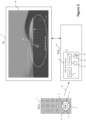
Figure 1 illustrates an example in which a particular embodiment of an on-screen grid control device is in a television; -
Figure 2 illustrates another example in which a particular embodiment of an on-screen grid control device is in an ancillary device (e.g. a Set-Top-Box); -
Figure 3 is a flowchart of an exemplary algorithm executed by the on-screen grid control device ofFigure 1 or2 ; and -
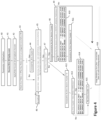
Figure 4 is a flowchart of another exemplary algorithm executed by the on-screen grid control device ofFigure 1 or2 . - The disclosure relates to a method (and corresponding device) for controlling the movements of an indicator (also referred to as "focus") or a positional indicator on an on-screen grid based on directional signals transmitted from a remote-control unit (or RCU) comprising directional keys (usually "UP", "RIGHT", "DOWN" and "LEFT" keys of a D-pad (Directional pad)). The positional indicator may be for example, a cursor.
- The disclosure can be applied particularly but not exclusively with a particular type of on-screen grid which is an on-screen keyboard (OSK) depicted on a display device (e.g. a TV) and that can be used instead of a physical keyboard. The on-screen keyboard is for example an alphanumeric on-screen keyboard (of any type: AZERTY, QWERTY, etc.). In alternative embodiments, it can be applied with any type of on-screen keyboard (broadly defined as a layout comprising keys, also referred to a as buttons, arranged essentially in rows and/or columns): lists, menus, etc.
- The disclosure can also be applied with other types of on-screen grids, such as for example on-screen menus, on-screen lists, etc.
- In all of the figures of the disclosure, similar elements and steps are designated by the same numerical reference sign.
- Referring now to
Figure 1 , there is shown an exemplary embodiment of an on-screen grid which is an on-screen keyboard control device (OSK control device) 8 internal to aTV 7. In a variant ofFigure 1 , shown inFigure 2 , theOSK control device 8 is external to theTV 7. - As already mentioned above, the disclosure applies also with any other type of on-screen grid (such as, for example, an on-screen menu, an on-screen list, etc.) including either at least one row and several columns or several rows and at least one column.
- The system may also include a remote-control unit (RCU) 1 having directional keys (in this embodiment,
UP key 5 ,RIGHT key 4, DOWNkey 3 andLEFT key 2 of a D-pad) and anOK key 6. Based on activation of one or more of the directional keys 2-5, the remote-control unit 1 transmitsdirectional signals 15 to theOSK control device 8. Alternatively, a keyboard device (not shown) with directional keys may be used to control the movement of the indicator on the on-screen grid. - An exemplary on-
screen keyboard 17 is depicted onscreen 16 of theTV 7. In the illustrated embodiment, the on-screen keyboard 17 is of the QWERTY type. - In the illustrated embodiment, the
OSK control device 8 comprises areceiver 9 configured to receive the signals transmitted by the remote-control unit 1, in particular signals 15. - The
OSK control device 8 also includes a non-volatile memory 12 (e.g., a read-only memory (ROM) or a hard disk), a volatile memory 11 (e.g. a random-access memory or RAM) and a processor (reprogrammable computation machine) 10. Thenon-volatile memory 12 is a non-transitory computer-readable carrier medium. It stores executableprogram code instructions 13, which are executed by theprocessor 10 in order to enable implementation of the method described below (discussed with reference toFigures 3 and4 ). Upon initialization, theprogram code instructions 13 are transferred from thenon-volatile memory 12 to thevolatile memory 11 so as to be executed by theprocessor 10. Thevolatile memory 11 likewise includes registers for storing the variables and parameters required for this execution. - All the steps of the method described below (discussed with reference to
Figures 3 and4 ) can be implemented by theOSK control device 8, by the execution of a set of program code instructions executed by a reprogrammable computing machine such as theprocessor 10 or a microcontroller, or by a dedicated computing machine or component, such as a FPGA (Field Programmable Gate Array), an ASIC (Application-Specific Integrated Circuit) or any dedicated hardware component. - In other words, the disclosure is not limited to the purely software-based implementation of
Figure 1 , in the form of computer program instructions, but that it can also be implemented in hardware form or any form combining a hardware portion and a software portion. - The OSK control device 8 (and more precisely the
processor 10 when executing the program code instructions 13) is configured for: - receiving the
signals 15 for moving the indicator on the on-screen keyboard 17 (via the receiver 9); - moving a indicator 18 (also referred to as "focus") on the on-
screen keyboard 17 based on the received signals 15 (in the example shown inFigure 1 , the indicator 18 is positioned on the letter "t"); and - when receiving at least one signal indicating that one of the directional keys 2-5 is activated, triggering a reaction time for moving the indicator. In other word, the reaction time for moving the indicator is a key-repeat feature after an initial key-repeat delay (hereinafter referred to as "KEY REPEAT DELAY FIRST").
- The reaction time for moving the indicator has a key-repeat rate defined as the inverse of a delay between two successive positions of the indicator on the on-
screen keyboard 17. For example, with a delay of 200ms between two successive positions of the indicator, the key-repeat rate is: R = 1/(200ms) = 5 repeats per second. - According to one embodiment, the reaction time for moving the indicator is variable and takes at least two different values based at least on a number of jumps between successive positions of the indicator after triggering an initial key-repeat feature.
- In a particular embodiment, the reaction time may have a first value if the number of jump is lower than a first number of indicator moves, and a second value, lower than the first value, if the number of jumps is greater than or equal to the first number of indicator moves.
- In a particular embodiment, the second value of the reaction time is greater than the inverse of the initial key-repeat delay.
- In a particular embodiment, the reaction time may have a third value, lower than the second value, if the indicator has reached a current position that is an edge of the on-screen keyboard and if a jump function between opposite edges of the on-screen keyboard is implemented.
- Other characteristics of the key-repeat feature according to the disclosure are presented below, with a detailed description of first and second algorithms carried out by the
OSK control device 8. -
Figure 2 illustrates a second exemplary embodiment in which the on-screen grid is an OSK control device 8 (e.g. as defined above in relation toFigure 1 ) in anancillary device 14 which is external to theTV 7. Theancillary device 14 may be for example a set-top-box, a BlueRay player, a game console, etc. In a variant ofFigure 2 , theOSK control device 8 may also be external to theancillary device 14. -
Figure 3 is a flowchart of a first algorithm (also referred to as "smart key-repeat algorithm") carried out by theOSK control device 8 ofFigure 1 or2 . - In order to implement the first algorithm according to a particular embodiment, we introduce four key-repeat time-intervals, e.g., reaction times for moving the indicator (in a variant, the last one is not used):
- KEY_REPEAT_DELAY_FIRST is applied before triggering the key-repeat feature, after a press (KeyDown event) on one of the directional keys (also referred to as "D-pad key") 2-5 (and therefore also after a first indicator movement is performed).
- KEY_REPEAT_DELAY_GO is linked to another parameter: KEY REPEAT NB BEFORE CRUISE. Generally, the user doesn't use the long press of one of the D-pad keys 2-5 to focus close characters. For example, on a QWERTY on-screen keyboard (as shown in
Figures 1 and2 ), if the indicator is on the "Q", the user will press the RIGHT key 4 twice to move (focus) the indicator to the "E". In the disclosure, if the key-repeat feature is started (i.e. if KEY_REPEAT_DELAY_FIRST has elapsed and the user still presses one of the D-pad keys 2-5), the indicator can move faster on the close characters. - KEY_REPEAT_DELAY_CRUISE is applied when the indicator has moved far enough from the origin (according to KEY REPEAT NB BEFORE CRUISE).
- KEY REPEAT DELAY BORDER is only used if the system allows the indicator the indicator to be moved from one border to another (i.e. cycling focus on rows/columns: e.g. LEFT key 2 when the indicator is on the first column focuses the last character on the right; on a QWERTY keyboard,
LEFT key 2 on the "Q" leads the indicator to the "P". On a long D-pad key press, ergonomics is improved if the indicator is slowed down on the borders. - Each of the last three key-repeat time-intervals (KEY_REPEAT_DELAY_GO, KEY_REPEAT_DELAY_CRUISE and KEY REPEAT DELAY BORDER) can be seen as a delay (time interval) between two successive positions of the indicator 18 on the
OSK 17. Therefore, the inverse of each of these last three key-repeat time-intervals is a different possible value of the variable key-repeat rate (reaction time for moving the indicator). - In one embodiment, the values used for the different parameters defined above are as follows:
- KEY_REPEAT_NB_BEFORE_CRUISE = 3;
- KEY_REPEAT-DELAY_FIRST = 200 ms;
- KEY_REPEAT_DELAY_GO = 80 ms (and therefore a first value of the variable key-repeat rate: V1 = 1/(80 ms));
- KEY_REPEAT_DELAY_CRUISE = 120 ms (and therefore a second value of the variable key-repeat rate: V2 = 1/(120 ms), which is lower than the first value V1 and greater than the inverse of KEY_REPEAT_DELAY_FIRST);
- KEY_REPEAT_DELAY_BORDER = 270ms (and therefore a third value of the variable key-repeat rate: V3 = 1/(270 ms), which is lower than the second value V2).
- With such values, if the user activates the D-
pad RIGHT key 4 to go from the "Q" to the "U" on the QWERTY on-screen keyboard 17, it takes: - 720 ms if the OSK control device performs a wait before each movement of the indicator (the sequence is as follows: wait of 200 ms, movement from Q to W, wait of 80 ms, movement from W to E, wait of 80 ms, movement from E to R, wait of 120 ms, movement from R to T, wait of 120 ms, movement from T to Y, wait of 120 ms and movement from Y to U); or
- 600 ms if the OSK control device performs a wait after each movement of the indicator (the sequence is as follows: movement from Q to W, wait of 200 ms, movement from W to E, wait of 80 ms, movement from E to R, wait of 80 ms, movement from R to T, wait of 120 ms, movement from T to Y, wait of 120 ms and movement from Y to U).
- Of course, other values can be used for the aforesaid different parameters. The accuracy gets better with longer delays. However, the system feels more reactive with small values, and it's often faster to roughly reach a keyboard zone and fine-tune the focus position, rather than slowing down the system to get absolutely no fine-tuning. So, it's a compromise between speed and pure accuracy. This will be considered in the second algorithm, which is detailed below with respect to
Figure 4 and enables a customization of such values. - We now detail the different steps of the first algorithm shown in
Figure 3 . - In
step 30, a parameter initialization is performed as follows: - Key_Repeat_Counter = 0
- D-pad_Key_History = [ ] (empty)
- In
step 31, the OSK control device receives a signal indicating a press (KeyDown event) on one of the D-pad keys 2-5 of the remote-control unit (RCU). - In
step 32, the OSK control device applies a movement associated with the pressed D-pad key, i.e. moves the indicator on the on-screen keyboard, from one position to the next (i.e. a jump between two successive positions) according to the pressed D-pad key (e.g. the OSK control device applies a jump of the indicator from the "Q" to the "W" on the on-screen keyboard 17, in case of a press on the D-pad RIGHT key 4). - In
step 33, the OSK control device records the indicator movement ofstep 32, by completing a history variable, named "D-pad_Key_History" (used in the second algorithm offigure 4 ), i.e. by adding to this history variable the movement carried out instep 32 and associated with the pressed D-pad key. For example, in case of a press on the D-pad RIGHT key 4, the movement "RIGHT" is added to the history variable. - In
step 34, the OSK control device increments by one a key-repeat counter (named "Key_Repeat_Counter"), which is used to count the number of indicator jumps between successive keyboard positions. - In
step 35, the OSK control device detects if the indicator is on a border (first/last column/row) of the on-screen keyboard 17. - In the case of a negative answer in
step 35, the algorithm continues instep 36, in which the OSK control device performs a wait step, whose duration depends on the value of "Key_Repeat_Counter": - if Key_Repeat_Counter = 1, the duration of the wait step is KEY REPEAT DELAY FIRST;
- if Key Repeat Counter ≤ KEY REPEAT NB BEFORE CRUISE, the duration of the wait step is KEY_REPEAT_DELAY_GO;
- if Key Repeat_Counter > KEY REPEAT NB BEFORE CRUISE, the duration of the wait step is KEY_REPEAT_DELAY_CRUISE.
- In an alternative embodiment of
step 36, if Key_Repeat_Counter ≤ KEY_REPEAT_NB_BEFORE_CRUISE, the duration of the wait step (i.e. KEY_REPEAT_DELAY_GO) is variable and takes a different value for each value of Key_Repeat_Counter greater than "1" and lower or equal to KEY_REPEAT_NB_BEFORE_CRUISE. - For example, with KEY REPEAT NB BEFORE CRUISE = 3:
- KEY REPEAT DELAY GO = 1/3 * KEY_REPEAT_NB_DELAY_CRUISE = 1/3 * 120 = 40 ms, if Key_Repeat_Counter = 2; and
- KEY REPEAT DELAY GO = 2/3 * KEY_REPEAT_NB_DELAY_CRUISE = 2/3 * 120 = 80 ms, if Key_Repeat_Counter = 3.
- In the case of a positive answer in
step 35, the algorithm continues instep 37, in which the OSK control device performs a wait step whose duration is KEY REPEAT DELAY BORDER. - After
step step 38, in which the OSK control device detects if it has received a directional signal indicating a release (KeyUp event) of the D-pad key which was indicated as pressed instep 31. - In the case of a negative answer in
step 38, the algorithm goes back to step 32 (the key-repeat feature is still active since the user has not yet released the D-pad key. - In the case of a positive answer in
step 38, the algorithm continues infinal step 39 in which the OSK control device resets "Key_Repeat_Counter" to zero (end of the key-repeat feature). - In the embodiment of
Figure 3 , the OSK control device performs a wait step (step 36 or 37) after each movement of the indicator (step 32). - In an alternative embodiment,
step 32 is carried out aftersteps step 38, and in the case of a negative answer instep 38, the algorithm goes back tostep 33. Thus, the OSK control device performs a wait step (step 36 or 37) before each movement of the indicator (step 32). -
Figure 4 is a flowchart of a second algorithm (also referred to as "user customized speed algorithm") carried out by the on-screen keyboard control device ofFigure 1 or2 . - The aim is to allow the on-screen
keyboard control device 8 to learn from the user and adapt at least one of the four key-repeat time-intervals discussed above, namely: - KEY_REPEAT_DELAY_FIRST;
- KEY_REPEAT_DELAY_GO (and therefore the first value V1 of the variable key-repeat rate);
- KEY_REPEAT_DELAY_CRUISE (and therefore the second value V2 of the variable key-repeat rate) and
- KEY_REPEAT_DELAY_BORDER (and therefore the third value V3 of the variable key-repeat rate).
- In the following exemplary embodiment, a single algorithm allows the user to increase/decrease three delay times (KEY_REPEAT_DELAY_FIRST, KEY_REPEAT_DELAY_GO and KEY REPEAT DELAY CRUISE) of the same adjust step named KEY_REPEAT_LEARNING_ADJUST_STEP (= 5ms for instance) at the same time.
- In variants we can have:
- a specific learning algorithm for each key-repeat delay, and/or
- a different value of KEY_REPEAT_LEARNING_ADJUST_STEP for each key-repeat delay, and/or
- a first step (INCREASING_ADJUST_STEP) for an increase of the key-repeat time-interval(s) being learned and a second step (DECREASING_ADJUST_STEP) for a decrease of the key-repeat time-interval(s) being learned, with the value of the second step being different from the value of the first step.
- To decide when speeding up or down the key-repeat feature, the
OSK control device 8 monitors antagonist (forward-backward) moves of the indicator 18 (also referred to as "position-fix patterns") to detect if speed is too high or too low, and therefore to decide if the key-repeat time-intervals being learned must be increased or decreased. - In a particular embodiment, an antagonist move is defined by a sequence of moves of the indicator executed before receiving an OK validation signal transmitted from the remote-control unit (RCU):
- at least N jumps according to a first direction, with N ≥ 2;
- followed by M jump(s) according to a second direction opposite to said first direction, with M = 1 or M = 2.
- For instance, with the aforesaid definition:
- the sequence "right > right > right > right > left > OK" is an antagonist move (the keyboard indicator moved too fast, the user had to move the indicator backwards one or two moves before selecting a character with the OK key);
- the sequence "up > right > left > OK" is not considered an antagonist move (the user may move unconsciously when looking for a character).
- As perfect accuracy for indicator moves generally means a slow system. It's not the best solution. The system becomes spineless in term of user experience, but also it alters the performance: it is often quicker to move fast and fine-tune, than getting to the target slowly in one shot. So, the antagonist moves are analyzed according to the usage and duration thereof.
- For instance, a number P (e.g., 2 ≤ P ≤ 4, and in a particular embodiment: P = 3) of antagonist moves (N, M) detected during a time duration D1 (e.g., 10s ≤ D1 ≤ 30s, and in a particular embodiment: D1 = one session of duration R seconds, with R = 20 s) triggers the speed decrease (i.e. an increase of the key-repeat time-intervals being learned). In the same way, if the user makes no antagonist move (N, M) during a time duration D2 (e.g. 40s ≤ D2 ≤ 120s, and in a particular embodiment: D2 = K sessions of duration R seconds, with K = 4 and R = 20 s), it triggers the speed increase (i.e. a decrease of the key-repeat time-intervals being learned).
- The different steps of the second algorithm shown in
Figure 4 (particular embodiment for speeding up the system) are described below. The aforesaid customizable system parameters R, P and K are named respectively: - NAV_MONITORING_SESSION_DURATION;
- NAV_ERROR_THRESHOLD; and
- PERFECT_SESSION_THRESHOLD.
- In
step 40, a parameter initialization is performed as follows: - Usage_Monitoring_Start_Date = current date
- Nav_Error_Counter = 0
- Consecutive_No_Error_Session_Counter = 0
- Note: Usage_Monitoring_Start_Date is used as time and initialized when the on-screen keyboard is called/displayed.
- In
step 41, the OSK control device receives a signal indicating a release (KeyUp event) of theOK key 6 of the remote-control unit (RCU) 1. - In
step 42, the OSK control device applies (i.e. enters) the character selected (focused) by the indicator 18 on the on-screen keyboard 17. - In
step 43, the OSK control device checks the content of the history variable named "D-pad_Key_History" which stores the indicator movements (seestep 33 ofFigure 3 ), in order to detect an error, i.e. an antagonist move (N, M) of the indicator 18 as defined above. - If an antagonist move is detected in
step 43, the algorithm continues instep 44, in which the OSK control device increments by one the counter named "Nav_Error_Counter", which counts the number of antagonist move. - A
step 45 is carried out afterstep 44, or directly afterstep 43 if no antagonist move is detected in thisstep 43. Instep 45, the OSK control device checks if a current monitoring session has ended. This is the case is the following condition is satisfied:
Current Date - Usage_Monitoring_Start_Date > NAV_MONITORING_SESSION_DURATION - In the case of a negative answer in
step 45, the algorithm goes to an end step 46 ("do nothing"). - In the case of a positive answer in
step 45, the algorithm goes to step 47 in which the OSK control device checks if "Nav_Error_Counter" is equal to zero. - In the case of a positive answer in
step 47, the algorithm goes to step 48 in which the OSK control device increments by one the counter named "Consecutive_No_Error_Session_Counter", which counts the number of consecutive session without antagonist move. -
Step 48 is followed by astep 49 in which the OSK control device checks if "Consecutive_No_Error_Session_Counter" is equal to "PERFECT_SESSION_THRESHOLD". - In the case of a positive answer in
step 49, the algorithm goes to step 410 in which the OSK control device decreases one or more of the three delay times (KEY REPEAT DELAY FIRST, KEY REPEAT DELAY GO and KEY_REPEAT_DELAY_CRUISE) of the adjust step KEY_REPEAT_LEARNING_ADJUST_STEP. Then it goes to step 411, in which "Consecutive_No_Error_Session_Counter" is reset to zero, and then to afinal step 416 in which the OSK control device resets "Usage_Monitoring_Start_Date" to the current date (thus starting a new monitoring session). - In the case of a negative answer in
step 49, the algorithm goes directly to thefinal step 416. - In the case of a negative answer in
step 47, the algorithm goes to step 412, in which the OSK control device resets "Consecutive_No_Error_Session_Counter" to zero, and then to step 413 in which the OSK control device checks if "Nav Error Counter" is equal to NAVERROR THRESHOLD. - In the case of a positive answer in
step 413, the algorithm goes to step 414 in which the OSK control device increases three delays (KEY_REPEAT_DELAY_FIRST, KEY REPEAT DELAY GO and KEY REPEAT DELAY_CRUISE) of the adjust step KEY_REPEAT_LEARNING_ADJUST_STEP. Then it goes to astep 415, in which "Nav_Error_Counter" is reset to zero, and then to thefinal step 416. - In the case of a negative answer in
step 413, the algorithm goes directly to step 415. - The present description illustrates the principles of the present disclosure. It will thus be appreciated that those skilled in the art will be able to devise various arrangements that, although not explicitly described or shown herein, embody the principles of the disclosure and are included within its scope.
- All examples and conditional language recited herein are intended for educational purposes to aid the reader in understanding the principles of the disclosure and the concepts contributed by the inventors to furthering the art, and are to be construed as being without limitation to such specifically recited examples and conditions.
- Moreover, all statements herein reciting principles, aspects, and embodiments of the disclosure, as well as specific examples thereof, are intended to encompass both structural and functional equivalents thereof. Additionally, it is intended that such equivalents include both currently known equivalents as well as equivalents developed in the future, i.e., any elements developed that perform the same function, regardless of structure.
- Thus, for example, it will be appreciated by those skilled in the art that the diagrams presented herein represent conceptual views of illustrative circuitry embodying the principles of the disclosure. Similarly, it will be appreciated that any flow charts, flow diagrams, state transition diagrams, pseudocode and the like represent various processes which may be substantially represented in computer readable media and so executed by a computer or processor, whether or not such computer or processor is explicitly shown.
- The functions of the various elements shown in the figures may be provided through the use of dedicated hardware as well as hardware capable of executing software in association with appropriate software. When provided by a processor, the functions may be provided by a single dedicated processor, by a single shared processor, or by a plurality of individual processors, some of which may be shared. Moreover, explicit use of the term "processor" or "controller" should not be construed to refer exclusively to hardware capable of executing software, and may implicitly include, without limitation, digital signal processor (DSP) hardware, read only memory (ROM) for storing software, random access memory (RAM), and nonvolatile storage.
- Other hardware, conventional and/or custom, may also be included. Similarly, any switches shown in the figures are conceptual only. Their function may be carried out through the operation of program logic, through dedicated logic, through the interaction of program control and dedicated logic, or even manually, the particular technique being selectable by the implementer as more specifically understood from the context.
- In the claims, hereof, any element expressed as a means for performing a specified function is intended to encompass any way of performing that function including, for example, a) a combination of circuit elements that performs that function or b) software in any form, including, therefore, firmware, microcode or the like, combined with appropriate circuitry for executing that software to perform the function. The disclosure as defined by such claims resides in the fact that the functionalities provided by the various recited means are combined and brought together in the manner which the claims call for. It is thus regarded that any means that can provide those functionalities are equivalent to those shown herein.
Claims (8)
- A method, comprising:receiving (31, 38) at a display device (7) a series of signals (15) transmitted from a remote-control unit (1) comprising directional keys, wherein the series of signals indicates activation of one of the directional keys; anduntil detection (38) of reception of a signal indicating release of the activated directional key, repeating:moving (32) an indicator (18) on a grid (17) depicted on the display device (7), the movement associated with the activated directional key; andwaiting (36, 37) a given time;wherein the given time has:a first value T1 in case the indicator is on a border of the grid (17) and a jump between opposite borders is enabled;a second value T2 after a first move in case the indicator is not on the border;a third value T3 after a number of moves greater than one and lower than a pre-set value in case the indicator is not on the border; anda fourth value T4 after a number of moves at least equal to the pre-set value and in case the indicator is not on the border;wherein T1>T2>T4>T3.
- The method according to claim 1, wherein the grid comprises at least one row and a plurality of columns or a plurality of rows and at least one column.
- The method according to claim 1 or 2, wherein said grid (17) is one of:an on-screen keyboard;an on-screen menu; andan on-screen list.
- A device (8), comprising:a receiver, configured to receive a series of signals (15) transmitted from a remote-control unit (1) comprising directional keys, wherein the series of signals indicates activation of one of the directional keys; anda processor, configured to:
until detection of reception of a signal indicating release of the activated directional key, repeat:move an indicator (18) on a grid (17) depicted on a display device (7), the movement associated with the activated directional key; andwait a given time;wherein the given time has:a first value T1 in case the indicator is on a border of the grid (17) and a jump between opposite borders is enabled;a second value T2 after a first move in case the indicator is not on the border;a third value T3 after a number of moves greater than one and lower than a pre-set value in case the indicator is not on the border; anda fourth value T4 after a number of moves at least equal to the pre-set value and in case the indicator is not on the border;wherein T1>T2>T4>T3. - The device according to claim 4, wherein the grid comprises at least one row and a plurality of columns or a plurality of rows and at least one column.
- The device according to claim 4 or 5, wherein said grid (17) is one of:an on-screen keyboard;an on-screen menu; andan on-screen list.
- A system, comprising:a remote-control unit (1) comprising directional keys; anda device according to any one of claims 4-6.
- A computer program product for a programmable apparatus, the computer program product comprising a sequence of instructions for implementing a method according to any one of claims 1-3, when loaded into and executed by the programmable apparatus.
Priority Applications (1)
| Application Number | Priority Date | Filing Date | Title |
|---|---|---|---|
| EP23194143.6A EP4258089B1 (en) | 2018-08-08 | 2018-08-08 | On-screen item grid control method, and corresponding device, system and computer program product |
Applications Claiming Priority (2)
| Application Number | Priority Date | Filing Date | Title |
|---|---|---|---|
| EP23194143.6A EP4258089B1 (en) | 2018-08-08 | 2018-08-08 | On-screen item grid control method, and corresponding device, system and computer program product |
| EP18306090.4A EP3608768A1 (en) | 2018-08-08 | 2018-08-08 | On-screen item grid control method and device, and corresponding display device and ancillary device |
Related Parent Applications (1)
| Application Number | Title | Priority Date | Filing Date |
|---|---|---|---|
| EP18306090.4A Division EP3608768A1 (en) | 2018-08-08 | 2018-08-08 | On-screen item grid control method and device, and corresponding display device and ancillary device |
Publications (3)
| Publication Number | Publication Date |
|---|---|
| EP4258089A2 true EP4258089A2 (en) | 2023-10-11 |
| EP4258089A3 EP4258089A3 (en) | 2023-12-13 |
| EP4258089B1 EP4258089B1 (en) | 2025-06-18 |
Family
ID=63452586
Family Applications (2)
| Application Number | Title | Priority Date | Filing Date |
|---|---|---|---|
| EP18306090.4A Ceased EP3608768A1 (en) | 2018-08-08 | 2018-08-08 | On-screen item grid control method and device, and corresponding display device and ancillary device |
| EP23194143.6A Active EP4258089B1 (en) | 2018-08-08 | 2018-08-08 | On-screen item grid control method, and corresponding device, system and computer program product |
Family Applications Before (1)
| Application Number | Title | Priority Date | Filing Date |
|---|---|---|---|
| EP18306090.4A Ceased EP3608768A1 (en) | 2018-08-08 | 2018-08-08 | On-screen item grid control method and device, and corresponding display device and ancillary device |
Country Status (2)
| Country | Link |
|---|---|
| US (1) | US11064242B2 (en) |
| EP (2) | EP3608768A1 (en) |
Family Cites Families (11)
| Publication number | Priority date | Publication date | Assignee | Title |
|---|---|---|---|---|
| US4313113A (en) * | 1980-03-24 | 1982-01-26 | Xerox Corporation | Cursor control |
| US7233316B2 (en) * | 2003-05-01 | 2007-06-19 | Thomson Licensing | Multimedia user interface |
| US8456534B2 (en) * | 2004-10-25 | 2013-06-04 | I-Interactive Llc | Multi-directional remote control system and method |
| JP2007094836A (en) * | 2005-09-29 | 2007-04-12 | Sony Ericsson Mobilecommunications Japan Inc | Electronic equipment, portable telephone terminal and key input control method |
| TW201027399A (en) * | 2009-01-09 | 2010-07-16 | E Lead Electronic Co Ltd | Method for aiding control of cursor movement through a track pad |
| KR101589179B1 (en) * | 2009-08-31 | 2016-02-12 | 엘지전자 주식회사 | Digital broadcast receiver controlled by screen remote controller and space remote controller and control method for the same |
| JP5544336B2 (en) * | 2011-07-26 | 2014-07-09 | 京セラドキュメントソリューションズ株式会社 | Symbol input device and image forming apparatus having the same |
| US20150301621A1 (en) * | 2014-04-21 | 2015-10-22 | I/O Interconnect Inc. | Method for controlling cursor speed |
| US9983691B2 (en) * | 2014-09-04 | 2018-05-29 | Home Box Office, Inc. | Styleable custom button repeat |
| US20160105627A1 (en) * | 2014-10-11 | 2016-04-14 | Gary Streuter | Assignment and characteristics of multiple letters, characters, numbers, strokes and symbols to an individual physical key on a physical keypad integrated into an external remote control device and used for data input on the screen of the electronic device |
| US10031596B2 (en) * | 2016-07-21 | 2018-07-24 | Lenovo Enterprise Solutions (Singapore) Pte. Ltd. | Sensitivity adjustment for a pointing device |
-
2018
- 2018-08-08 EP EP18306090.4A patent/EP3608768A1/en not_active Ceased
- 2018-08-08 EP EP23194143.6A patent/EP4258089B1/en active Active
-
2019
- 2019-07-30 US US16/525,703 patent/US11064242B2/en active Active
Also Published As
| Publication number | Publication date |
|---|---|
| EP4258089A3 (en) | 2023-12-13 |
| EP4258089B1 (en) | 2025-06-18 |
| US11064242B2 (en) | 2021-07-13 |
| US20200050334A1 (en) | 2020-02-13 |
| EP3608768A1 (en) | 2020-02-12 |
Similar Documents
| Publication | Publication Date | Title |
|---|---|---|
| US20130307790A1 (en) | Methods And Apparatus For Device Control | |
| US11243615B2 (en) | Systems, methods, and media for providing an enhanced remote control having multiple modes | |
| US10296140B2 (en) | Information processing method for avoidance of a mis-touch and electronic device thereof | |
| US8855966B2 (en) | Electronic device having proximity sensor and method for controlling the same | |
| US10175880B2 (en) | Display apparatus and displaying method thereof | |
| CN107930122A (en) | Information processing method, device and storage medium | |
| EP2503439A1 (en) | Method for positioning a cursor on a screen | |
| CN109918004B (en) | Virtual role control method and device | |
| CN108525303A (en) | Object control method and apparatus in interactive application | |
| JP6499928B2 (en) | Information processing apparatus, information processing system, information processing method, and information processing program | |
| US9591250B2 (en) | Remote control with feedback for blind navigation | |
| CN109847369B (en) | Method and device for switching postures of virtual roles in game | |
| EP3940518B1 (en) | Method for moving interface elements, system, vehicle and storage medium | |
| CN108635850A (en) | Information processing method, device and storage medium | |
| AU2022234961B2 (en) | State based action buttons | |
| US11064242B2 (en) | On-screen item grid control method and device, and corresponding display device and ancillary device | |
| US10764625B2 (en) | Smart touch | |
| KR20120100655A (en) | System and method for inputting combination-type character on virtual keyboard using movement sensor and touch sensor | |
| EP3438809A1 (en) | Control instruction identification method and apparatus, and storage medium | |
| EP2887197A1 (en) | Method for selecting an electronic content to be displayed on a display of an electronic device | |
| JP2018097443A (en) | Input system and input program | |
| US20160105627A1 (en) | Assignment and characteristics of multiple letters, characters, numbers, strokes and symbols to an individual physical key on a physical keypad integrated into an external remote control device and used for data input on the screen of the electronic device | |
| CA2976239C (en) | Organic haptic interface | |
| TWI862310B (en) | Handheld electronic device and physical button operation method thereof | |
| US20230351913A1 (en) | Adaptive keyboard teaching system |
Legal Events
| Date | Code | Title | Description |
|---|---|---|---|
| PUAI | Public reference made under article 153(3) epc to a published international application that has entered the european phase |
Free format text: ORIGINAL CODE: 0009012 |
|
| STAA | Information on the status of an ep patent application or granted ep patent |
Free format text: STATUS: THE APPLICATION HAS BEEN PUBLISHED |
|
| AC | Divisional application: reference to earlier application |
Ref document number: 3608768 Country of ref document: EP Kind code of ref document: P |
|
| AK | Designated contracting states |
Kind code of ref document: A2 Designated state(s): AL AT BE BG CH CY CZ DE DK EE ES FI FR GB GR HR HU IE IS IT LI LT LU LV MC MK MT NL NO PL PT RO RS SE SI SK SM TR |
|
| REG | Reference to a national code |
Ref country code: DE Ref legal event code: R079 Free format text: PREVIOUS MAIN CLASS: G06F0003038000 Ref country code: DE Ref legal event code: R079 Ref document number: 602018082833 Country of ref document: DE Free format text: PREVIOUS MAIN CLASS: G06F0003038000 Ipc: G06F0003048920 |
|
| PUAL | Search report despatched |
Free format text: ORIGINAL CODE: 0009013 |
|
| AK | Designated contracting states |
Kind code of ref document: A3 Designated state(s): AL AT BE BG CH CY CZ DE DK EE ES FI FR GB GR HR HU IE IS IT LI LT LU LV MC MK MT NL NO PL PT RO RS SE SI SK SM TR |
|
| RIC1 | Information provided on ipc code assigned before grant |
Ipc: H04N 21/47 20110101ALN20231109BHEP Ipc: H04N 21/422 20110101ALI20231109BHEP Ipc: G06F 3/023 20060101ALI20231109BHEP Ipc: G06F 3/04892 20220101AFI20231109BHEP |
|
| STAA | Information on the status of an ep patent application or granted ep patent |
Free format text: STATUS: REQUEST FOR EXAMINATION WAS MADE |
|
| 17P | Request for examination filed |
Effective date: 20240410 |
|
| RBV | Designated contracting states (corrected) |
Designated state(s): AL AT BE BG CH CY CZ DE DK EE ES FI FR GB GR HR HU IE IS IT LI LT LU LV MC MK MT NL NO PL PT RO RS SE SI SK SM TR |
|
| GRAP | Despatch of communication of intention to grant a patent |
Free format text: ORIGINAL CODE: EPIDOSNIGR1 |
|
| STAA | Information on the status of an ep patent application or granted ep patent |
Free format text: STATUS: GRANT OF PATENT IS INTENDED |
|
| RIC1 | Information provided on ipc code assigned before grant |
Ipc: H04N 21/47 20110101ALN20250217BHEP Ipc: H04N 21/422 20110101ALI20250217BHEP Ipc: G06F 3/023 20060101ALI20250217BHEP Ipc: G06F 3/04892 20220101AFI20250217BHEP |
|
| INTG | Intention to grant announced |
Effective date: 20250311 |
|
| GRAS | Grant fee paid |
Free format text: ORIGINAL CODE: EPIDOSNIGR3 |
|
| GRAA | (expected) grant |
Free format text: ORIGINAL CODE: 0009210 |
|
| STAA | Information on the status of an ep patent application or granted ep patent |
Free format text: STATUS: THE PATENT HAS BEEN GRANTED |
|
| P01 | Opt-out of the competence of the unified patent court (upc) registered |
Free format text: CASE NUMBER: APP_21176/2025 Effective date: 20250505 |
|
| AC | Divisional application: reference to earlier application |
Ref document number: 3608768 Country of ref document: EP Kind code of ref document: P |
|
| AK | Designated contracting states |
Kind code of ref document: B1 Designated state(s): AL AT BE BG CH CY CZ DE DK EE ES FI FR GB GR HR HU IE IS IT LI LT LU LV MC MK MT NL NO PL PT RO RS SE SI SK SM TR |
|
| REG | Reference to a national code |
Ref country code: GB Ref legal event code: FG4D |
|
| REG | Reference to a national code |
Ref country code: CH Ref legal event code: EP |
|
| REG | Reference to a national code |
Ref country code: DE Ref legal event code: R096 Ref document number: 602018082833 Country of ref document: DE |
|
| REG | Reference to a national code |
Ref country code: CH Ref legal event code: EP |
|
| REG | Reference to a national code |
Ref country code: IE Ref legal event code: FG4D |
|
| REG | Reference to a national code |
Ref country code: NL Ref legal event code: FP |
|
| PGFP | Annual fee paid to national office [announced via postgrant information from national office to epo] |
Ref country code: NL Payment date: 20250825 Year of fee payment: 8 |
|
| PG25 | Lapsed in a contracting state [announced via postgrant information from national office to epo] |
Ref country code: FI Free format text: LAPSE BECAUSE OF FAILURE TO SUBMIT A TRANSLATION OF THE DESCRIPTION OR TO PAY THE FEE WITHIN THE PRESCRIBED TIME-LIMIT Effective date: 20250618 |
|
| PGFP | Annual fee paid to national office [announced via postgrant information from national office to epo] |
Ref country code: DE Payment date: 20250827 Year of fee payment: 8 |
|
| REG | Reference to a national code |
Ref country code: LT Ref legal event code: MG9D |
|
| PG25 | Lapsed in a contracting state [announced via postgrant information from national office to epo] |
Ref country code: NO Free format text: LAPSE BECAUSE OF FAILURE TO SUBMIT A TRANSLATION OF THE DESCRIPTION OR TO PAY THE FEE WITHIN THE PRESCRIBED TIME-LIMIT Effective date: 20250918 Ref country code: GR Free format text: LAPSE BECAUSE OF FAILURE TO SUBMIT A TRANSLATION OF THE DESCRIPTION OR TO PAY THE FEE WITHIN THE PRESCRIBED TIME-LIMIT Effective date: 20250919 |
|
| PG25 | Lapsed in a contracting state [announced via postgrant information from national office to epo] |
Ref country code: BG Free format text: LAPSE BECAUSE OF FAILURE TO SUBMIT A TRANSLATION OF THE DESCRIPTION OR TO PAY THE FEE WITHIN THE PRESCRIBED TIME-LIMIT Effective date: 20250618 |
|
| PGFP | Annual fee paid to national office [announced via postgrant information from national office to epo] |
Ref country code: GB Payment date: 20250826 Year of fee payment: 8 |
|
| PG25 | Lapsed in a contracting state [announced via postgrant information from national office to epo] |
Ref country code: HR Free format text: LAPSE BECAUSE OF FAILURE TO SUBMIT A TRANSLATION OF THE DESCRIPTION OR TO PAY THE FEE WITHIN THE PRESCRIBED TIME-LIMIT Effective date: 20250618 |
|
| PGFP | Annual fee paid to national office [announced via postgrant information from national office to epo] |
Ref country code: FR Payment date: 20250825 Year of fee payment: 8 |
|
| PG25 | Lapsed in a contracting state [announced via postgrant information from national office to epo] |
Ref country code: RS Free format text: LAPSE BECAUSE OF FAILURE TO SUBMIT A TRANSLATION OF THE DESCRIPTION OR TO PAY THE FEE WITHIN THE PRESCRIBED TIME-LIMIT Effective date: 20250918 |
|
| PG25 | Lapsed in a contracting state [announced via postgrant information from national office to epo] |
Ref country code: LV Free format text: LAPSE BECAUSE OF FAILURE TO SUBMIT A TRANSLATION OF THE DESCRIPTION OR TO PAY THE FEE WITHIN THE PRESCRIBED TIME-LIMIT Effective date: 20250618 |
|
| PG25 | Lapsed in a contracting state [announced via postgrant information from national office to epo] |
Ref country code: PT Free format text: LAPSE BECAUSE OF FAILURE TO SUBMIT A TRANSLATION OF THE DESCRIPTION OR TO PAY THE FEE WITHIN THE PRESCRIBED TIME-LIMIT Effective date: 20251020 |
|
| REG | Reference to a national code |
Ref country code: AT Ref legal event code: MK05 Ref document number: 1804816 Country of ref document: AT Kind code of ref document: T Effective date: 20250618 |
|
| PG25 | Lapsed in a contracting state [announced via postgrant information from national office to epo] |
Ref country code: IS Free format text: LAPSE BECAUSE OF FAILURE TO SUBMIT A TRANSLATION OF THE DESCRIPTION OR TO PAY THE FEE WITHIN THE PRESCRIBED TIME-LIMIT Effective date: 20251018 |
|
| PG25 | Lapsed in a contracting state [announced via postgrant information from national office to epo] |
Ref country code: SM Free format text: LAPSE BECAUSE OF FAILURE TO SUBMIT A TRANSLATION OF THE DESCRIPTION OR TO PAY THE FEE WITHIN THE PRESCRIBED TIME-LIMIT Effective date: 20250618 Ref country code: AT Free format text: LAPSE BECAUSE OF FAILURE TO SUBMIT A TRANSLATION OF THE DESCRIPTION OR TO PAY THE FEE WITHIN THE PRESCRIBED TIME-LIMIT Effective date: 20250618 |
|
| PG25 | Lapsed in a contracting state [announced via postgrant information from national office to epo] |
Ref country code: CZ Free format text: LAPSE BECAUSE OF FAILURE TO SUBMIT A TRANSLATION OF THE DESCRIPTION OR TO PAY THE FEE WITHIN THE PRESCRIBED TIME-LIMIT Effective date: 20250618 |
|
| PG25 | Lapsed in a contracting state [announced via postgrant information from national office to epo] |
Ref country code: PL Free format text: LAPSE BECAUSE OF FAILURE TO SUBMIT A TRANSLATION OF THE DESCRIPTION OR TO PAY THE FEE WITHIN THE PRESCRIBED TIME-LIMIT Effective date: 20250618 |
|
| PG25 | Lapsed in a contracting state [announced via postgrant information from national office to epo] |
Ref country code: EE Free format text: LAPSE BECAUSE OF FAILURE TO SUBMIT A TRANSLATION OF THE DESCRIPTION OR TO PAY THE FEE WITHIN THE PRESCRIBED TIME-LIMIT Effective date: 20250618 |
|
| PG25 | Lapsed in a contracting state [announced via postgrant information from national office to epo] |
Ref country code: SK Free format text: LAPSE BECAUSE OF FAILURE TO SUBMIT A TRANSLATION OF THE DESCRIPTION OR TO PAY THE FEE WITHIN THE PRESCRIBED TIME-LIMIT Effective date: 20250618 |
|
| PG25 | Lapsed in a contracting state [announced via postgrant information from national office to epo] |
Ref country code: ES Free format text: LAPSE BECAUSE OF FAILURE TO SUBMIT A TRANSLATION OF THE DESCRIPTION OR TO PAY THE FEE WITHIN THE PRESCRIBED TIME-LIMIT Effective date: 20250618 |
|
| PG25 | Lapsed in a contracting state [announced via postgrant information from national office to epo] |
Ref country code: RO Free format text: LAPSE BECAUSE OF FAILURE TO SUBMIT A TRANSLATION OF THE DESCRIPTION OR TO PAY THE FEE WITHIN THE PRESCRIBED TIME-LIMIT Effective date: 20250618 |
|
| REG | Reference to a national code |
Ref country code: DE Ref legal event code: R097 Ref document number: 602018082833 Country of ref document: DE |
|
| REG | Reference to a national code |
Ref country code: CH Ref legal event code: H13 Free format text: ST27 STATUS EVENT CODE: U-0-0-H10-H13 (AS PROVIDED BY THE NATIONAL OFFICE) Effective date: 20260324 |
|
| PG25 | Lapsed in a contracting state [announced via postgrant information from national office to epo] |
Ref country code: MC Free format text: LAPSE BECAUSE OF FAILURE TO SUBMIT A TRANSLATION OF THE DESCRIPTION OR TO PAY THE FEE WITHIN THE PRESCRIBED TIME-LIMIT Effective date: 20250618 |
|
| PG25 | Lapsed in a contracting state [announced via postgrant information from national office to epo] |
Ref country code: DK Free format text: LAPSE BECAUSE OF FAILURE TO SUBMIT A TRANSLATION OF THE DESCRIPTION OR TO PAY THE FEE WITHIN THE PRESCRIBED TIME-LIMIT Effective date: 20250618 |
|
| PG25 | Lapsed in a contracting state [announced via postgrant information from national office to epo] |
Ref country code: IT Free format text: LAPSE BECAUSE OF FAILURE TO SUBMIT A TRANSLATION OF THE DESCRIPTION OR TO PAY THE FEE WITHIN THE PRESCRIBED TIME-LIMIT Effective date: 20250618 Ref country code: LU Free format text: LAPSE BECAUSE OF NON-PAYMENT OF DUE FEES Effective date: 20250808 |
|
| PG25 | Lapsed in a contracting state [announced via postgrant information from national office to epo] |
Ref country code: CH Free format text: LAPSE BECAUSE OF NON-PAYMENT OF DUE FEES Effective date: 20250831 |
|
| PLBE | No opposition filed within time limit |
Free format text: ORIGINAL CODE: 0009261 |
|
| STAA | Information on the status of an ep patent application or granted ep patent |
Free format text: STATUS: NO OPPOSITION FILED WITHIN TIME LIMIT |
|
| REG | Reference to a national code |
Ref country code: CH Ref legal event code: L10 Free format text: ST27 STATUS EVENT CODE: U-0-0-L10-L00 (AS PROVIDED BY THE NATIONAL OFFICE) Effective date: 20260430 Ref country code: BE Ref legal event code: MM Effective date: 20250831 |
|
| 26N | No opposition filed |
Effective date: 20260319 |
|
| PG25 | Lapsed in a contracting state [announced via postgrant information from national office to epo] |
Ref country code: LT Free format text: LAPSE BECAUSE OF FAILURE TO SUBMIT A TRANSLATION OF THE DESCRIPTION OR TO PAY THE FEE WITHIN THE PRESCRIBED TIME-LIMIT Effective date: 20250618 |
|
| PG25 | Lapsed in a contracting state [announced via postgrant information from national office to epo] |
Ref country code: BE Free format text: LAPSE BECAUSE OF NON-PAYMENT OF DUE FEES Effective date: 20250831 Ref country code: IE Free format text: LAPSE BECAUSE OF NON-PAYMENT OF DUE FEES Effective date: 20250808 |
|
| PG25 | Lapsed in a contracting state [announced via postgrant information from national office to epo] |
Ref country code: SE Free format text: LAPSE BECAUSE OF FAILURE TO SUBMIT A TRANSLATION OF THE DESCRIPTION OR TO PAY THE FEE WITHIN THE PRESCRIBED TIME-LIMIT Effective date: 20250618 |