EP4258075A1 - Systems and methods for parameterization of inspected bladed rotor analysis - Google Patents
Systems and methods for parameterization of inspected bladed rotor analysis Download PDFInfo
- Publication number
- EP4258075A1 EP4258075A1 EP23166856.7A EP23166856A EP4258075A1 EP 4258075 A1 EP4258075 A1 EP 4258075A1 EP 23166856 A EP23166856 A EP 23166856A EP 4258075 A1 EP4258075 A1 EP 4258075A1
- Authority
- EP
- European Patent Office
- Prior art keywords
- repair
- various embodiments
- evaluation
- ibr
- processor
- Prior art date
- Legal status (The legal status is an assumption and is not a legal conclusion. Google has not performed a legal analysis and makes no representation as to the accuracy of the status listed.)
- Pending
Links
- 238000000034 method Methods 0.000 title claims abstract description 105
- 238000004458 analytical method Methods 0.000 title claims description 138
- 230000008439 repair process Effects 0.000 claims abstract description 287
- 238000011156 evaluation Methods 0.000 claims abstract description 176
- 238000007689 inspection Methods 0.000 claims abstract description 119
- 230000007547 defect Effects 0.000 claims abstract description 58
- 239000000203 mixture Substances 0.000 claims description 85
- 238000004088 simulation Methods 0.000 claims description 29
- 230000004044 response Effects 0.000 claims description 27
- 238000004519 manufacturing process Methods 0.000 claims description 16
- 230000008859 change Effects 0.000 claims description 14
- 238000004891 communication Methods 0.000 claims description 6
- 230000035945 sensitivity Effects 0.000 claims description 6
- 238000003860 storage Methods 0.000 claims description 6
- 230000003116 impacting effect Effects 0.000 claims description 5
- 230000003068 static effect Effects 0.000 claims description 4
- 230000008569 process Effects 0.000 description 76
- 239000000463 material Substances 0.000 description 43
- 238000013461 design Methods 0.000 description 34
- 238000012360 testing method Methods 0.000 description 32
- 230000015654 memory Effects 0.000 description 25
- 238000002156 mixing Methods 0.000 description 17
- 238000012916 structural analysis Methods 0.000 description 14
- 230000002829 reductive effect Effects 0.000 description 13
- 239000000654 additive Substances 0.000 description 10
- 230000000996 additive effect Effects 0.000 description 10
- 238000011161 development Methods 0.000 description 8
- 238000012546 transfer Methods 0.000 description 7
- 230000008901 benefit Effects 0.000 description 6
- 239000000446 fuel Substances 0.000 description 6
- 238000003754 machining Methods 0.000 description 6
- 238000011960 computer-aided design Methods 0.000 description 5
- 230000009467 reduction Effects 0.000 description 5
- 230000001105 regulatory effect Effects 0.000 description 5
- XEEYBQQBJWHFJM-UHFFFAOYSA-N Iron Chemical compound [Fe] XEEYBQQBJWHFJM-UHFFFAOYSA-N 0.000 description 4
- PXHVJJICTQNCMI-UHFFFAOYSA-N Nickel Chemical compound [Ni] PXHVJJICTQNCMI-UHFFFAOYSA-N 0.000 description 4
- 229910001069 Ti alloy Inorganic materials 0.000 description 4
- 229910045601 alloy Inorganic materials 0.000 description 4
- 239000000956 alloy Substances 0.000 description 4
- 230000006870 function Effects 0.000 description 4
- 230000003287 optical effect Effects 0.000 description 4
- 238000013528 artificial neural network Methods 0.000 description 3
- 238000010586 diagram Methods 0.000 description 3
- 230000000694 effects Effects 0.000 description 3
- 239000012530 fluid Substances 0.000 description 3
- 230000001965 increasing effect Effects 0.000 description 3
- 238000012986 modification Methods 0.000 description 3
- 230000004048 modification Effects 0.000 description 3
- 238000012545 processing Methods 0.000 description 3
- 230000005355 Hall effect Effects 0.000 description 2
- 238000005452 bending Methods 0.000 description 2
- 230000008878 coupling Effects 0.000 description 2
- 238000010168 coupling process Methods 0.000 description 2
- 238000005859 coupling reaction Methods 0.000 description 2
- 229910052742 iron Inorganic materials 0.000 description 2
- 230000000670 limiting effect Effects 0.000 description 2
- 238000010801 machine learning Methods 0.000 description 2
- 238000012423 maintenance Methods 0.000 description 2
- 239000011159 matrix material Substances 0.000 description 2
- 229910052759 nickel Inorganic materials 0.000 description 2
- 230000001902 propagating effect Effects 0.000 description 2
- 239000010935 stainless steel Substances 0.000 description 2
- 229910001220 stainless steel Inorganic materials 0.000 description 2
- VYZAMTAEIAYCRO-UHFFFAOYSA-N Chromium Chemical compound [Cr] VYZAMTAEIAYCRO-UHFFFAOYSA-N 0.000 description 1
- 241000237509 Patinopecten sp. Species 0.000 description 1
- 230000001133 acceleration Effects 0.000 description 1
- 238000003491 array Methods 0.000 description 1
- 230000009286 beneficial effect Effects 0.000 description 1
- 238000005266 casting Methods 0.000 description 1
- 230000001413 cellular effect Effects 0.000 description 1
- 239000003086 colorant Substances 0.000 description 1
- 230000006835 compression Effects 0.000 description 1
- 238000007906 compression Methods 0.000 description 1
- 238000002591 computed tomography Methods 0.000 description 1
- 238000005094 computer simulation Methods 0.000 description 1
- 230000008021 deposition Effects 0.000 description 1
- 238000006073 displacement reaction Methods 0.000 description 1
- 230000005284 excitation Effects 0.000 description 1
- 230000001939 inductive effect Effects 0.000 description 1
- 230000000873 masking effect Effects 0.000 description 1
- 230000005055 memory storage Effects 0.000 description 1
- 238000003801 milling Methods 0.000 description 1
- 230000036961 partial effect Effects 0.000 description 1
- 230000002093 peripheral effect Effects 0.000 description 1
- 238000010248 power generation Methods 0.000 description 1
- 235000020637 scallop Nutrition 0.000 description 1
- 239000007787 solid Substances 0.000 description 1
- 230000001131 transforming effect Effects 0.000 description 1
- 230000001052 transient effect Effects 0.000 description 1
- 230000007704 transition Effects 0.000 description 1
- 238000010200 validation analysis Methods 0.000 description 1
- 230000000007 visual effect Effects 0.000 description 1
- 239000011800 void material Substances 0.000 description 1
- 238000003466 welding Methods 0.000 description 1
Images


Classifications
-
- F—MECHANICAL ENGINEERING; LIGHTING; HEATING; WEAPONS; BLASTING
- F01—MACHINES OR ENGINES IN GENERAL; ENGINE PLANTS IN GENERAL; STEAM ENGINES
- F01D—NON-POSITIVE DISPLACEMENT MACHINES OR ENGINES, e.g. STEAM TURBINES
- F01D5/00—Blades; Blade-carrying members; Heating, heat-insulating, cooling or antivibration means on the blades or the members
- F01D5/005—Repairing methods or devices
-
- B—PERFORMING OPERATIONS; TRANSPORTING
- B23—MACHINE TOOLS; METAL-WORKING NOT OTHERWISE PROVIDED FOR
- B23P—METAL-WORKING NOT OTHERWISE PROVIDED FOR; COMBINED OPERATIONS; UNIVERSAL MACHINE TOOLS
- B23P6/00—Restoring or reconditioning objects
- B23P6/002—Repairing turbine components, e.g. moving or stationary blades, rotors
-
- F—MECHANICAL ENGINEERING; LIGHTING; HEATING; WEAPONS; BLASTING
- F01—MACHINES OR ENGINES IN GENERAL; ENGINE PLANTS IN GENERAL; STEAM ENGINES
- F01D—NON-POSITIVE DISPLACEMENT MACHINES OR ENGINES, e.g. STEAM TURBINES
- F01D5/00—Blades; Blade-carrying members; Heating, heat-insulating, cooling or antivibration means on the blades or the members
- F01D5/34—Rotor-blade aggregates of unitary construction, e.g. formed of sheet laminae
-
- G—PHYSICS
- G06—COMPUTING; CALCULATING OR COUNTING
- G06F—ELECTRIC DIGITAL DATA PROCESSING
- G06F30/00—Computer-aided design [CAD]
- G06F30/10—Geometric CAD
- G06F30/15—Vehicle, aircraft or watercraft design
-
- F—MECHANICAL ENGINEERING; LIGHTING; HEATING; WEAPONS; BLASTING
- F05—INDEXING SCHEMES RELATING TO ENGINES OR PUMPS IN VARIOUS SUBCLASSES OF CLASSES F01-F04
- F05D—INDEXING SCHEME FOR ASPECTS RELATING TO NON-POSITIVE-DISPLACEMENT MACHINES OR ENGINES, GAS-TURBINES OR JET-PROPULSION PLANTS
- F05D2230/00—Manufacture
- F05D2230/80—Repairing, retrofitting or upgrading methods
-
- G—PHYSICS
- G06—COMPUTING; CALCULATING OR COUNTING
- G06F—ELECTRIC DIGITAL DATA PROCESSING
- G06F30/00—Computer-aided design [CAD]
- G06F30/20—Design optimisation, verification or simulation
- G06F30/23—Design optimisation, verification or simulation using finite element methods [FEM] or finite difference methods [FDM]
Definitions
- the present disclosure relates to repair analysis methods and systems, and more particularly, the repair analysis systems and methods for bladed rotors of gas turbine engines.
- Gas turbine engines typically include a compressor, a combustor section, and a turbine.
- the compressor and the turbine typically include a series of alternating rotors and stators.
- a rotor generally comprises a rotor disk and a plurality of blades.
- the rotor may be an integrally bladed rotor ("IBR") or a mechanically bladed rotor.
- the rotor disk and blades in the IBR are one piece (i.e., monolithic, or nearly monolithic) with the blades spaced around the circumference of the rotor disk.
- Conventional IBRs may be formed using a variety of technical methods including integral casting, machining from a solid billet, or by welding or bonding the blades to the rotor disk.
- Repair methods for IBRs may be limited to maintaining the IBR within tolerances of a product definition for a design of the IBR, a volume or thickness of material addition, and/or a volume or thickness of material removal. Additionally, repair analysis methods for IBRs may fail to consider loads and/or boundary conditions encountered during engine operation included in the aerodynamic, structural, or other functional assessment of the IBR. In this regard, a damaged IBR may be scrapped because it is believed to unrepairable within the geometric assessment constraints (e.g., tolerances, material removal, material addition, etc.) without consideration of the functional assessment constraints (e.g., aerodynamic stability, structural durability, etc.). By being limited in this manner, less expensive repair options and/or more optimal repairs (e.g., in terms of aerodynamic or structural capability, etc.) that could otherwise be acceptable may be avoided.
- geometric assessment constraints e.g., tolerances, material removal, material addition, etc.
- functional assessment constraints e.g., aerodynamic stability, structural durability, etc.
- a method is disclosed herein.
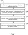
- the method can comprise: receiving an inspection data corresponding to a geometry of an inspected bladed rotor; performing a baseline evaluation based on the inspection data; determining a plurality of candidate repair profiles for a defect of the inspected bladed rotor; performing an updated evaluation for each candidate repair profile in the plurality of candidate repair profiles; selecting a selected candidate repair profile in the plurality of candidate repair profiles based on the updated evaluation for each candidate repair profile in the plurality of candidate repair profiles; and performing a repair based on the selected candidate repair profile.
- the baseline evaluation and the updated evaluations include an engine performance evaluation, an engine operability evaluation, a module aerodynamic performance evaluation, and a structural evaluation.
- the method can further comprise balancing output parameters from the updated evaluations prior to selecting the selected candidate repair profile.
- the plurality of candidate repair profiles includes a repair blend profile and a repair patch profile.
- the selected candidate repair profile is selected based on an impact to a second inspected bladed rotor based on an output parameter from the updated evaluation.
- the baseline evaluation and the updated evaluation includes performing a modal analysis, a static analysis, a turning and loss change analysis, and an engine performance analysis.
- the baseline evaluation includes evaluating a digital representation based on the geometry and an initial repair blend profile.
- the article of manufacture includes a tangible, non-transitory computer-readable storage medium having instructions stored thereon that, in response to execution by a processor, cause the processor to perform operations comprising: receiving, by the processor, a digital representation of a geometry of an inspected bladed rotor; receiving, by the processor, engine data from a gas turbine engine that had the inspected bladed rotor installed thereon; performing, by the processor, a baseline evaluation of the digital representation based on the digital representation, an initial repair shape, and the engine data; performing, by the processor, an updated evaluation for each candidate repair profile in a plurality of candidate repair profiles for the inspected bladed rotor; and generating, by the processor, results from the updated evaluation for each candidate repair profile.
- the operations further comprise receiving, by the processor, a candidate repair profile in the plurality of candidate repair profiles based on impacting the updated evaluation for a second inspected bladed rotor for a module level analysis.
- the baseline evaluation and the updated evaluations include an engine performance evaluation, an engine operability evaluation, a module aerodynamic performance evaluation, and a structural evaluation.
- the operations further comprise generating, by the processor, shape sensitivity data to a repair shape for the inspected bladed rotor.
- the operations further comprise determining, by the processor, whether the updated evaluation for each candidate repair profile in the plurality of candidate repair profiles meets an experience based criteria.
- the operations further comprise determining, by the processor, whether the updated evaluation for each candidate repair profile in the plurality of candidate repair profiles meets a deterministic criteria.
- the updated evaluation for each candidate repair profile in the plurality of candidate repair profiles includes a module level evaluation including a plurality of inspected bladed rotors.
- the system comprises: an inspection system configured to scan an inspected bladed rotor and generate a point cloud of at least a portion of the inspected bladed rotor; and an analysis system in electronic communication with the inspection system, the analysis system comprising a tangible, non-transitory computer-readable storage medium having instructions stored thereon that, in response to execution by a processor, cause the processor to perform operations comprising: receive, by the processor, a data set based on the point cloud; generate, by the processor, a digital representation of the inspected bladed rotor based on the data set; perform, by the processor, a baseline evaluation based on the digital representation; perform, by the processor, an updated evaluation for each candidate repair profile in a plurality of candidate repair profiles; and generate, by the processor, results from the updated evaluation for each candidate repair profile.
- the baseline evaluation and the updated evaluations include an engine performance evaluation, an engine operability evaluation, a module aerodynamic performance evaluation, and a structural evaluation.
- the operations further comprise receiving, by the processor, a candidate repair profile in the plurality of candidate repair profiles based on impacting the updated evaluation for a second inspected bladed rotor for a module level analysis.
- the operations further comprise generating, by the processor, shape sensitivity data to a repair shape for the inspected bladed rotor.
- the operations further comprise determining, by the processor, whether the updated evaluation for each candidate repair profile in the plurality of candidate repair profiles meets a deterministic criteria.
- the updated evaluation includes an aerodynamic simulation and a structural simulation.
- references to "a,” “an”, or “the” may include one or more than one and that reference to an item in the singular may also include the item in the plural. Further, all ranges may include upper and lower values and all ranges and ratio limits disclosed herein may be combined.
- tail refers to the direction associated with the tail (e.g., the back end) of an aircraft, or generally, to the direction of exhaust of the gas turbine.
- forward refers to the direction associated with the nose (e.g., the front end) of an aircraft, or generally, to the direction of flight or motion.
- Gas turbine engine 20 may be a two-spool turbofan that generally incorporates a fan section 22, a compressor section 24, a combustor section 26, and a turbine section 28.
- fan section 22 can drive air along a path of bypass airflow B while compressor section 24 can drive air along a core flow path C for compression and communication into combustor section 26 then expansion through turbine section 28.
- turbofan gas turbine engine 20 depicted as a turbofan gas turbine engine 20 herein, it should be understood that the concepts described herein are not limited to use with turbofans as the teachings may be applied to other types of turbine engines including three-spool architectures, single spool architecture or the like.
- Gas turbine engine 20 may generally comprise a low speed spool 30 and a high speed spool 32 mounted for rotation about an engine central longitudinal axis A-A' relative to an engine static structure 36 or engine case via several bearing systems 38, 38-1, etc.
- Engine central longitudinal axis A-A' is oriented in the Z direction on the provided X-Y-Z axes. It should be understood that various bearing systems 38 at various locations may alternatively or additionally be provided, including for example, bearing system 38, bearing system 38-1, etc.
- Low speed spool 30 may generally comprise an inner shaft 40 that interconnects a fan 42, a low pressure compressor 44 and a low pressure turbine 46.
- Inner shaft 40 may be connected to fan 42 through a geared architecture 48 that can drive fan 42 at a lower speed than low speed spool 30.
- Geared architecture 48 may comprise a gear assembly 60 enclosed within a gear housing 62.
- Gear assembly 60 couples' inner shaft 40 to a rotating fan structure.
- High speed spool 32 may comprise an outer shaft 50 that interconnects a high pressure compressor 52 and high pressure turbine 54.
- a combustor 56 may be located between high pressure compressor 52 and high pressure turbine 54.
- a mid-turbine frame 57 of engine static structure 36 may be located generally between high pressure turbine 54 and low pressure turbine 46.
- Mid-turbine frame 57 may support one or more bearing systems 38 in turbine section 28.
- Inner shaft 40 and outer shaft 50 may be concentric and rotate via bearing systems 38 about the engine central longitudinal axis A-A', which is collinear with their longitudinal axes.
- A-A' the engine central longitudinal axis A-A'
- the core airflow may be compressed by low pressure compressor 44 then high pressure compressor 52, mixed and burned with fuel in combustor 56, then expanded over high pressure turbine 54 and low pressure turbine 46.
- Turbines 46, 54 rotationally drive the respective low speed spool 30 and high speed spool 32 in response to the expansion.
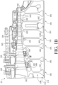
- high pressure compressor 52 of the compressor section 24 of gas turbine engine 20 is provided.
- the high pressure compressor 52 includes a plurality of blade stages 101 (i.e., rotor stages) and a plurality of vane stages 105 (i.e., stator stages).
- the blade stages 101 may each include an integrally bladed rotor ("IBR") 100, such that the blades 103 and rotor disks 102 are formed from a single integral component (i.e., a monolithic component formed of a single piece).
- IBR integrally bladed rotor
- the present disclosure is not limited in this regard.
- the inspection, analysis, and repair systems disclosed herein can be utilized with bladed rotors formed of separate blades 103 and rotor disks 102 and still be within the scope of this disclosure.
- the blades 103 extend radially outward from the rotor disk 102.
- the gas turbine engine 20 may further include an exit guide vane stage 106 that defines the aft end of the high pressure compressor 52.
- the low pressure compressor 44 may include a plurality of blade stages 101 and vane stages 105, each blade stage in the plurality of blade stages 101 including the IBR 100 and still be within the scope of this disclosure.
- the plurality of blade stages 101 form a stack of IBRs 110, which define, at least partially, a rotor module 111 of the high pressure compressor 52 of the gas turbine engine 20.
- the IBR 100 includes a rotor disk 102 and a plurality of blades 103 extending radially outward from the rotor disk 102.
- the debris When debris is ingested into the gas turbine engine 20, the debris can pass into the primary flowpath. Due to the rotation of the blades 103 in the primary flowpath, the debris can contact one or more of the blades 103. This contact can cause damage or wear to a blade 103, or a set of the blades 103.
- Disclosed herein are systems and methods for inspection, analysis, and repair of an IBR 100 and for returning an IBR 100 back to service after inspection (or after repair). The systems and methods disclosed herein facilitate more robust dispositions the more the process is utilized. In this regard, the systems and methods disclosed herein account for various performance parameters and select a repair process based on balancing these various performance parameters, in accordance with various embodiments.
- a damaged portion 130 from FIG. 2 of an IBR 100 including a substantial number of defects 140 e.g., damage, wear, etc.
- the size and shape of the defects 140 illustrated in FIG. 3 are exaggerated for illustrative effect.
- the defects 140 can extend to all of the blades 103 of the IBR 100, the rotor disk 102, a set of the blades 103 of the IBR 100, a single blade in the blades 103, none of the blades 103, or the like.
- a blending operation can be performed on the IBR 100.
- a blending operation uses a material removal process, such as milling or computer numerical control (CNC) machining, to remove the damaged portion of the IBR 100 and smooth the resulting voids such that the IBR 100 can be re-introduced into service for further use (i.e., meeting structural and/or aerodynamic criteria for further use in service).
- CNC computer numerical control
- the damaged portion 130 of an inspected IBR 131 with an additional blending mask 150 applied to each of the locations of the defects 140 is illustrated, in accordance with various embodiments.
- the blending masks 150 are highly exaggerated in scale for explanatory effect.
- the blending masks 150 can be physical masking applied to the IBR 100, or shaded colors on computer simulations of the IBR 100. In either case, the blending masks 150 indicate what portions of the material of the blade 103 and / or the rotor disk 102 should be removed in order for the IBR 100 to be suitable for utilization in the gas turbine engine 20 after blending.
- the blending mask 150 ensures that accurate and consistent blends are made in operations that manual removal operations for removal of material. Although illustrated as having blending mask 150, the present disclosure is not limited in this regard. For example, repair process can be performed, as described further herein, using automated processes, such as computer numerical control (CNC) machining or the like without the use of a blending mask 150 and still be within the scope of this disclosure.
- CNC computer numerical control
- blending mask 150 Once the blending mask 150 has been applied, material is removed using the generally manual material removal operation resulting in a repaired blade portion 172 of a repaired IBR 170 including a plurality of repair blend profiles 160, as is illustrated in FIG. 5A .
- each repair blend profile in the plurality of repair blend profiles 160 is based, at least partially, on a defect shape of a respective defect 140 from FIG. 3 .
- the systems and methods disclosed herein facilitate a greater number of potential repair options for a respective defect 140 from FIG. 3 .
- a repair blend was too large and fell out of experience based functional criteria, an IBR 100 could be scrapped as opposed to being blended as described further herein and placed back into service.
- a repair patch could be utilized instead of a repair blend to fill a void as opposed to scrapping an IBR 100, as described further herein.
- the processes disclosed herein can result in a greater number of repair options, which can facilitate choosing a repair option based on improving a desired performance parameter, in accordance with various embodiments, as described further herein.
- explicit instructions are derived from the automated process and supplied to a computer numerical controlled (CNC) machine.
- CNC computer numerical controlled
- blending masks may not be utilized as the manual blending operation is replaced by the machine automated process.
- Blends of IBR 100 can be by either manual or automated processes, or a combination of those processes. In wholly automated processes, the creation of the mask can be omitted.
- a blend aspect ratio (e.g., a length - depth ratio) is maintained in order to ensure that there is a smooth and gradual transition from the edge of the undamaged blade 103 to the bottom of the deepest portion of the blend, and then back to the undamaged surface of the blade 103 on the other side of the blend.
- FIGs. 2-5A illustrate repair solutions applied to the IBR 100 in locations including the rotor disk 102, the blade 103, an edge 121 (e.g., a leading edge or a trailing edge), a tip 122, an airfoil surface 123 (e.g., a pressure surface or a suction surface), it can be appreciated that a repair of each location shown on the same blade 103 is unlikely.
- the various locations are shown for illustrative purposes of potential repair locations, in accordance with various embodiments.
- the illustrated defects 140, blending masks 150, and repair blend profiles 160 on the IBR 100 are exemplary of the limited applications and not of every repair made according to the description herein.
- a semi - automated (or fully automated) system is utilized to inspect, analyze, and repair an IBR 100, in accordance with various embodiments.
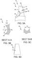
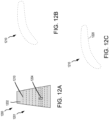
- repair blend profiles 160 can include a scallop shape (e.g., repair blend profile 162 from FIG. 5B ), a tear drop shape (e.g., repair blend profile 166 from FIG. 5A ), a material reduction along an edge (i.e., chord reduction) (e.g., repair blend profile 168 from FIG. 5D ), or the like.
- scallop shape e.g., repair blend profile 162 from FIG. 5B
- tear drop shape e.g., repair blend profile 166 from FIG. 5A
- a material reduction along an edge i.e., chord reduction
- the repair blend profile 162 comprises a convex shape and defines a recess in an outer surface of the repaired IBR 170 (e.g., a pressure surface, a suction surface, a rotor disk surface, or the like).
- the repair blend profile is recessed from the outer surface 164 of the repaired IBR 170.
- the repair blend profile 162 comprises a depth D1, a length L1 and a width W1.
- the repair blend has a length L1 that is greater than a width W1.
- the present disclosure is not limited in this regard.
- the length L1 can be equal to the width W1, in accordance with various embodiments.
- An aspect ratio of a blend profile refers to a length L1 dived by a width W1 of the repair blend profile.
- the repair blend profile is substantially symmetric about a plane defined by a first point, a second point and a third point.
- the first point can be a max depth location.
- the second point and the third point can define a line that measures a maximum length (e.g., length L1) of the repair blend, in various embodiments.
- the second point and the third point can define a line that measures a width in a perpendicular direction from the length L1.
- the present disclosure is not limited in this regard.
- substantially symmetrical is a first profile on a first side of the plane that is within a profile of between 0.01 inches (0.025 cm) and 0.25 inches (0.64 cm) from the second profile on the second side of the plane, or between 0.01 inches (0.025 cm) and 0.125 inches (0.32 cm), or between 0.01 inches (0.25 cm) and 0.0625 inches (0.16 cm).
- the repair blend profile can comprise a tear drop shape (e.g., repair blend profile 166 from FIG. 5B ), a chord reduction (i.e., shorting a chord length by a chord reduction length C1 along a span of the blade 103 of the repaired IBR 170 as shown in FIG. 5D ), or the like.
- the present disclosure is not limited in this regard.
- a defect e.g., defects 140 from FIG. 3
- a repair blend profile e.g., repair blend profile 162, 166
- the additive material 176 can be layers deposited by any additive manufacturing method.
- the additive material 176 can be a similar material to a material of the blade 103. For example, if the blade is a titanium alloy, the additive material 176 can also be a titanium alloy.
- the additive material 176 can have different material properties compared to the material of the blade 103.
- evaluations to ensure bond strength, properties for the additive material 176, etc. can be performed in response to analyzing a repair patch profile 174, in accordance with various embodiments.
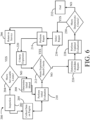
- process 200 for repairing an IBR 100 from FIG. 1B from a compressor section (e.g., compressor section 24) of a gas turbine engine 20 from FIG. 1A is illustrated, in accordance with various embodiments.
- the process 200 may be performed for one or more of IBR 100 in the compressor section 24 of the gas turbine engine 20.
- process 200 accumulates data over time, creating greater fidelity and improving future IBR repair determinations, in accordance with various embodiments.
- the process 200 comprises inspection of a bladed rotor (e.g., an IBR 100 from FIG. 1B ) (step 202).
- the dimensional inspection can be performed by an inspection system (e.g., inspection system 285 shown in FIGs. 7 and 8 further herein).
- the dimensional inspection can be facilitated by use of an optical scanner (e.g., structured light scanners, such as white light scanners, structured blue light scanners, or the like) and/or a coordinate-measuring machine.
- an optical scanner e.g., structured light scanners, such as white light scanners, structured blue light scanners, or the like
- a coordinate-measuring machine e.g., a coordinate-measuring machine.
- step 202 can further comprise scanning the IBR 100 with a scanner (e.g., structured light scanners, such as white light scanners, structured blue light scanners, and/or, a coordinate-measuring machine).
- a scanner e.g., structured light scanners, such as white light scanners, structured blue light scanners, and/or, a coordinate-measuring machine.
- a digital representation of the IBR 100 e.g., a point cloud, a surface model, or the like
- the defects 140 of the IBR 100 can be graphically depicted in a three-dimensional model (e.g., a Computer Aided Design (CAD) model or Finite Element Model (FEM), an aerodynamic model, or the like.
- CAD Computer Aided Design
- FEM Finite Element Model
- an FEM model (or aerodynamic model) that includes the defects 140 (i.e., with rough surfaces or the like), can cause issues with running structural and/or aerodynamic simulations.
- the inspection system 285 (as shown in FIGs. 7 and 8 ) can be configured to generate or determine an initial (or baseline) blend shape (e.g., repair blend profile 162 from FIG. 5B , repair blend profile 166 from FIG. 5A , etc.) based on data from inspection step 202 (i.e., scanner data), expertise (i.e., previously acceptable repair shapes or the like), etc. as described further herein.
- the inspection step 202 can be performed on an IBR in an uninstalled state or an installed state.
- the IBR 100 can be inspected while installed in the rotor module 111 in the high pressure compressor 52 of the gas-turbine engine 20 as illustrated in FIGs. 1A and 1B .
- a borescope can be utilized to inspect an IBR 100 while in an installed state, in accordance with various embodiments.
- the IBR 100 can be inspected via an inspection system 285 or a system 280 as described further herein.
- the three-dimensional model generated from step 202 includes a digital representation each defect of the IBR 100 from FIGs. 2-3 .
- the process 200 further comprises determining whether the IBR 100 meets serviceable limits (step 204).
- serviceable limits refers to objective parameter limits of defects (e.g., wear, damage, etc.) for the IBR 100.
- an objective parameter limit can be a threshold defect depth, a threshold defect length, a threshold defect aspect ratio, a threshold number of defects per blade, a threshold number of defects per IBR 100, any combination of the objective parameter limits disclosed herein, or the like.
- step 204 can be performed by an inspection system 285 or an analysis system 600 as described further herein.
- the present disclosure is not limited in this regard. If step 204 is performed by the inspection system 285, a determination on whether the IBR 100 is serviceable can be made rather quickly, on-site at an overhaul facility, in various embodiments. If step 204 is performed by the analysis system 600, a quick turnaround could still be achieved via cloud computing, or the like, as described further herein, in accordance with various embodiments. In this regard, step 204 can potentially be determined more quickly due to greater potential computing power in a cloud based environment.
- the process further comprises returning the IBR 100 to service (step 206).
- the IBR 100 can be re-installed on a gas turbine engine 20 from FIG. 1A if the IBR 100 is in an uninstalled state, or the IBR 100 can simply be approved for return to service if the IBR 100 is in an installed state.
- the IBR 100 is installed on the same gas turbine engine 20 from which it was removed from in response to being in an uninstalled state.
- the present disclosure is not limited in this regard, and the IBR 100 could be installed on a different gas turbine engine 20 from which it was removed and still be within the scope of this disclosure.
- an initial evaluation of the IBR 100 can be performed (step 210).
- the initial evaluation can include an initial, or baseline, blend profile (e.g., repair blend profile 162, repair blend profile 166, or repair blend profile 168 from FIGs. 5A-D ).
- an initial blend profile can be determined and/or generated for each defect 140 of the IBR 100.
- initial blend profiles can only be determined / generated for defects 140 that do not meet the objective defect parameter(s) from step 204.
- digital representation of a repair blend profile 160 is generated for all defects 140 of the IBR 100. The present disclosure is not limited in this regard.
- the initial blend profile is based on consistent parameters and is generated automatically via the process 200.
- each initial blend profile may be determined in step 208 to remove a predetermined amount of additional material and to generate a smooth blend across the entirety of the defect (e.g., transforming a digital representation of defects 140 to repair blend profiles 160).
- a model is generated in step 210 prior to the initial evaluation.
- the model generated in step 208 can be a three-dimensional model (e.g., a Computer Aided Design (CAD) model or Finite Element Model (FEM)), a plurality of two-dimensional section models (e.g., defining various cross-sections of a blade 103), or the like.
- CAD Computer Aided Design
- FEM Finite Element Model
- an initial model generated in step 208 is configured to greatly reduce a file size of inspection data from step 202 to transfer relevant inspection data to an external analysis system (e.g., analysis system 600 as described further herein).
- the scanner data can be converted in section data for an airfoil at various span lengths from a root of the airfoil, as described further herein.
- a point cloud generated from inspection data e.g., from a structured scanner or CMM machine as described previously herein
- excess data that may be irrelevant for analysis of the inspected IBR 100 can be removed, to facilitate a quick and/or easy transfer of the relevant data to the analysis system 600 as described further herein.
- the model generated in step 208 can be converted into a three-dimensional model for use in various third party software programs, such as ANSYS, ANSYS Workbench, ANSYS Computational Fluid Dynamics (CFD), or the like.
- the model from step 208 can be converted to a finite element model (FEM) for a structural analysis, an aerodynamic model for aerodynamic analysis, or the like.
- FEM finite element model
- a file size of the model from step 208 can be relatively small compared to a model size used in the structural analysis and/or the aerodynamic analysis as described further herein.
- an initial blend profile in step 208, the present disclosure is not limited in this regard.
- an initial blend profile may not be modeled and the actual defect may be modeled instead.
- the process 200 further comprises performing initial evaluations (step 210).
- the initial evaluations can be performed on a digital representation of the inspected IBR from step 202 with or without an initial blend profile from step 208 modeled therein (e.g., a "repaired IBR digital model" or an "inspected IBR digital model” as described further herein).
- structural, aerodynamic, and/or operability evaluations can be performed in step 210 for a digital representation of a repaired IBR 170 or an inspected IBR 131, in accordance with various embodiments.
- the repaired IBR digital model or the inspected IBR digital model can be a CAD model, an FEM model based on a specific analytical simulation being performed, a two dimensional section model (as described further herein), or the like.
- a repaired IBR as described herein refers to a repaired IBR 170 with at least one repaired blade portion 172 having at least one repair profile (e.g., repair blend profile 162, 166, or 168 from FIGs. 5A-D , repair patch profile 174, or the like).
- the digital representation of the repaired IBR digital model is based on the inspected IBR that was inspected in step 202 and modeled with initial blend profiles for a plurality of defects 140 in the IBR 100, in accordance with various embodiments.
- the process 200 can further comprise collecting data on a current state of the gas turbine engine 20 from FIG. 1A that had (or has) the inspected IBR 100 disposed thereon (step 205).
- the data can include a current physical state of the engine (e.g., module level and/or part level data).
- the physical state of the engine can include dimensional detail for each IBR in the rotor module 111 from FIG. 1B .
- all IBRs in the rotor module 111 can be inspected in accordance with step 202 and stored at step 205 prior to proceeding with the evaluation in step 210.
- the data can include recent engine operation data.
- recent engine operation data can include thrust, fuel burn, thrust specific fuel consumption, stall margin, compressor efficiency, temperature data, etc.
- the initial evaluations can in step 210 can be based on actual engine performance data, as opposed to design criteria data, in accordance with various embodiments.
- the initial evaluations performed in step 210 can be for engine performance, engine operability, aerodynamic module performance, aerodynamic part level performance, and/or structural performance.
- the initial evaluation in step 210 can be an engine performance evaluation.
- the engine performance evaluation can comprise a numerical propulsion system simulation (NPSS) (e.g., via a non-linear thermodynamic modeling environment), a reduced order engine model (e.g., via MATLAB or the like), influence coefficient matrix for gas path analysis, or the like.
- NPSS numerical propulsion system simulation
- input parameters for an engine performance evaluation can include a change in performance parameter (e.g., a change in flow capacity, a change in efficiency, and/or a change in clearance).
- the change in performance can be measured as compared to initial performance or design performance.
- An "initial performance” as disclosed herein refers to a performance of a gas turbine engine 20 from FIG. 1A directly after original manufacture.
- a "design performance” as disclosed herein refers to a design specification for the gas turbine engine 20 (i.e., a minimum level of performance for the gas turbine engine 20 from FIG. 1A ).
- output parameters for an engine performance analysis can include thrust, fuel burn, thrust specific fuel consumption, margins to maximum rated speed, pressure, and/or temperature, time on wing (e.g., for exhaust gas temperature margin, hot gas-path section repair intervals, and/or life limited parts).
- the output parameters can be evaluated to assess that engine specifications and engine metrics will be met for the repaired IBR or the inspected IBR without a repair, in accordance with various embodiments.
- the output parameters from the engine performance evaluation can be compared to engine metrics and/or engine specifications to determine whether the engine metrics and/or engine specifications are met for the respective initial blend profile from step 208 (or another repair option as described further herein) or the inspected IBR without a repair, in accordance with various embodiments.
- the engine metrics and/or engine specifications must be met in order to proceed to another evaluation.
- margins from the engine specifications and/or metrics can be optimized and/or balance with other evaluation factors, as described further herein. The present disclosure is not limited in this regard.
- the initial evaluation in step 210 can include an engine operability evaluation.
- the engine operability evaluation can comprise a numerical propulsion system simulation (NPSS) (e.g., via a non-linear thermodynamic modeling environment), a reduced order engine model (e.g., via MATLAB or the like), influence coefficient matrix for gas path analysis, or the like.
- NPSS numerical propulsion system simulation
- input parameters for an engine operability evaluation can include a change in performance parameter (e.g., a change in flow capacity, a change in efficiency, and/or a change in clearance).
- the change in operability can be measured as compared to initial operability or design operability.
- An "initial operability” as disclosed herein refers to a performance of a gas turbine engine 20 from FIG. 1A directly after original manufacture.
- a "design operability” as disclosed herein refers to a design specification for the gas turbine engine 20 (i.e., a minimum level of performance for the gas turbine engine 20 from FIG. 1A ).
- output parameters for an engine operability analysis can include remaining stall margin, transient time periods (e.g., for acceleration, deceleration, and/or starting of the gas turbine engine 20 from FIG. 1A ), stability bleed efficiency, compressor efficiency during inclement weather, or the like.
- the output parameters can be evaluated to assess that engine safety and regulatory criteria is met for the repaired IBR or the inspected IBR without a repair, in accordance with various embodiments.
- the output parameters from the engine operability evaluation can be compared to engine safety metrics and/or engine regulatory metrics to determine whether the engine safety metrics and/or engine regulatory metrics are met for the respective initial blend profile from step 208 (or another repair option as described further herein) or the inspected IBR without a repair, in accordance with various embodiments.
- the engine safety metrics and/or engine regulatory metrics must be met in order to proceed to another evaluation.
- margins from the engine safety metrics and/or engine regulatory metrics can be optimized and/or balance with other evaluation factors, as described further herein. The present disclosure is not limited in this regard.
- the initial evaluation in step 210 can include a module aerodynamic performance evaluation.
- the module aerodynamic evaluation can comprise a finite element analysis, a reduced order aerodynamic model (e.g., via MATLAB or the like), an empirical model based on empirical trends, or the like.
- input parameters for a module aerodynamic performance evaluation can include loss and turning models for the repaired IBR or the inspected IBR and operability limits (i.e., an operability envelope or the like) for the gas turbine engine 20 from FIG. 1A .
- a "loss and turning model" as described herein are models configured to determine probabilistic impact of geometric variability for a loss coefficient and turning angle for the repaired IBR or the inspected IBR, whichever IBR is being analyzed.
- output parameters can be analyzed.
- output parameters for a module aerodynamic performance analysis can include compressor efficiency, stall margin, or the like.
- the output parameters can be evaluated to assess that fuel burn, thrust capability, time on wing, and aerodynamic safety criteria are met for the repaired IBR or the inspected IBR without a repair, in accordance with various embodiments.
- the output parameters from the module aerodynamic performance evaluation can be compared to module aerodynamic design metrics (i.e., design efficiency and design stall margin for a nominal dimension IBR) to determine whether the module aerodynamic design metrics are met for the respective initial blend profile from step 208 (or another repair option as described further herein) or the inspected IBR without a repair, in accordance with various embodiments.
- the aerodynamic design metrics (or an acceptable deviation from the aerodynamic design metrics) must be met in order to proceed to another evaluation.
- margins from the aerodynamic design metrics can be optimized and/or balance with other evaluation factors, as described further herein. The present disclosure is not limited in this regard.
- the initial evaluation in step 210 can include a part aerodynamic performance evaluation.
- the part aerodynamic evaluation can comprise a finite element analysis, a reduced order aerodynamic model (e.g., via MATLAB or the like), an empirical model based on empirical trends, or the like.
- input parameters for a part aerodynamic performance evaluation can include airfoil geometry (e.g., determined from inspection data from the inspection step 202 of process 200), a description of a repair profile (e.g., location of repair and size of repair), or the like.
- the airfoil geometry can be in the form of two-dimensional section models, a three-dimensional finite element model, a text description of coordinates (e.g., two-dimensional or three-dimensional) for input into a reduced order aerodynamic model, or the like.
- output parameters can be used as input parameters in the module aerodynamic performance evaluation described above.
- output parameters for a part aerodynamic performance analysis can include change in turning angle and change in loss coefficient relative to a design IBR (e.g., a nominally dimensioned IBR).
- the initial evaluation in step 210 can include a low cycle fatigue (LCF) structural evaluation.
- the LCF structural evaluation can comprise a finite element analysis.
- a finite element model based on the inspection data from step 202 can be utilized to perform the LCF structural evaluation.
- input parameters for a LCF structural evaluation can include airfoil geometry (e.g., determined from inspection data from the inspection step 202 of process 200), a description of a repair profile (e.g., location of repair and size of repair), or the like.
- input parameters for LCF structural evaluations further comprise critical operating conditions (e.g., critical temperature and pressure conditions).
- output parameters for a LCF structural evaluation analysis can be steady stress (i.e., mean stress).
- the steady stress can be analyzed relative to a minimum number of flight cycles the airfoil could last without developing damage from the steady stress.
- an expected remaining life after repair can be determined and compared relative to a remaining life of the gas turbine engine 20 from FIG. 1A .
- the LCF structural evaluation can be balanced with other evaluations (e.g., a reduced life can be acceptable as long as the reduced life is above a minimum remaining life for the gas turbine engine 20 from FIG. 1A ), in accordance with various embodiments.
- input parameters for a HCF structural evaluation at the module level can include airfoil geometry (e.g., determined from inspection data from the inspection step 202 of process 200), a description of a repair profile (e.g., location of repair and size of repair), or the like.
- tuning margin is an acceptable margin in excitation frequency, as compared to a nominal design IBR.
- a tuning margin can be 5%, -3% to +4%, or the like. The present disclosure is not limited in this regard.
- the initial evaluation in step 210 can include a high cycle fatigue (HCF) structural evaluation at the part level.
- HCF structural evaluation at the part level can comprise a finite element analysis.
- a finite element model based on the inspection data from step 202 can be utilized to perform the HCF structural evaluation.
- input parameters for a HCF structural evaluation at the part level can include airfoil geometry (e.g., determined from inspection data from the inspection step 202 of process 200), a description of a repair profile (e.g., location of repair and size of repair), or the like.
- the input parameters can include critical operating conditions (e.g., critical temperature and pressure conditions) (e.g., for inputs in computational dynamics analysis).
- output parameters from the LCF evaluation can be utilized as input parameters in the HCF structural evaluation at the part level.
- the mean stress can be utilized as an assumption that the part is experiencing the mean stress during a vibratory response, in accordance with various embodiments.
- output parameters for an HCF structural evaluation analysis at the part level can be alternating stress of the repaired IBR (or the inspected IBR without the repair).
- the alternating stress can be analyzed relative to a Goodman margin.
- the alternating stress can be compared to a maximum alternating stress that could result in a crack, or damage to the repaired IBR.
- the Goodman margin can be debited for an additional factor of safety (e.g., 80% of maximum alternating stress, 70% of maximum alternating stress, or the like).
- the output parameters can further comprise flutter sensitivity due to the repair.
- a flutter margin relative to a design standard can be analyzed. As long as the flutter margin is within an acceptable range, the repaired IBR (or inspected IBR without a repair) can be deemed acceptable to return to service.
- the process 200 further comprises analyzing the repaired IBR digital model (step 210).
- the analysis in step 210 includes various evaluations, as described above.
- the various simulations can further include simulations to evaluate a modal assurance criteria (MAC), a resonant frequency, an aerodynamic efficiency, a stall margin, damage tolerance, dynamic stress from vibration, or the like.
- damage tolerance may be an optional criteria to analyze (e.g., if the bladed rotor is not an IBR but a bladed rotor having a distinct rotor disk and distinct blades).
- the simulations can be via various simulation software platforms described previously herein.
- analyzing the repaired IBR digital model can include optimizing the repair profile shape based on various parameters.
- step 210 can include iterating the repair profile shape based on the various evaluations and results of the various evaluations described above.
- the repair profile shape is only analyzed for the initial blend profile generated in step 208.
- the present disclosure is not limited in this regard.
- step 210 further comprises comparing the simulation results to experience based criteria.
- an IBR 100 is known, based on prior test data during development, to have a resonant frequency that varies by a threshold percentage (e.g., 3%, 5%, 8%, etc.) from a nominal frequency, and if a threshold number of the IBR 100 have been in service for a threshold number of cycles (e.g., 2,000 flight cycles, 10,000 flight cycles, or the like), then an experience based criteria for the resonant frequency can be created.
- a threshold percentage e.g., 3%, 5%, 8%, etc.
- a modal analysis determines a resonant frequency for the repaired IBR digital model is within the threshold percentage
- the experience based criteria for resonant frequency would be considered met because the experimental data from development that indicates that the IBR 100 varies in resonant frequency by the threshold percentage without issue has been validated by experience by the threshold number of the IBR 100 having been in service for the threshold number of cycles.
- the resonant frequency being acceptable within a threshold range of frequencies has been validated by experience in service.
- an IBR 100 is known, based on prior test data during development, to have a MAC that varies by a threshold percentage (e.g., 3%, 5%, 8%, etc.) from a nominal MAC, and if the threshold number of the IBR 100 have each been in service for the threshold number of cycles, then an experience based-criteria for the MAC can be created. For example, if the simulation to determine the MAC for the for repaired IBR digital model is less than the nominal MAC plus the threshold percentage, the MAC can be determined acceptable as being validated by experience in a similar manner as the resonant frequency example provided above.
- a threshold percentage e.g., 3%, 5%, 8%, etc.
- an IBR 100 is known, based on prior test data during development, to have an aerodynamic efficiency that varies by a threshold percentage (e.g., 3%, 5%, 8%, etc.) from a nominal aerodynamic efficiency, and if the threshold number of the IBR 100 have each been in service for the threshold number of cycles, then an experience based-criteria for the aerodynamic efficiency can be created. For example, if the simulation for the repaired IBR digital model has a greater aerodynamic efficiency than the nominal aerodynamic efficiency less the threshold percentage, than the aerodynamic efficiency being acceptable has been validated by experience in the field.
- a threshold percentage e.g., 3%, 5%, 8%, etc.
- the acceptable experience based criteria for aerodynamic efficiency can be based on being greater than the aerodynamic efficiency determined from testing and validated by experience in service, as opposed to being based on nominal less the threshold percentage.
- additional margin of error would be provided for the repaired IBR (i.e., a greater safety factor), in accordance with various embodiments.
- the present disclosure is not limited in this regard.
- an IBR 100 is known, based on prior test data during development, to have a stall margin that varies by a threshold percentage (e.g., 3%, 5%, 8%, etc.) from a nominal stall margin, and if the threshold number of the IBR 100 have each been in service for the threshold number of cycles, then an experience based-criteria for the stall margin can be created. For example, if the simulation to determine stall margin for the repaired IBR digital model has a greater stall margin than the nominal aerodynamic stall margin less the threshold percentage, than the stall margin being acceptable has been validated by experience in the field.
- a threshold percentage e.g., 3%, 5%, 8%, etc.
- the acceptable experience based criteria for stall margin can be based on being greater than the nominal stall margin determined from testing and validated by experience in service, as opposed to being based on nominal less the threshold percentage.
- additional margin of error would be provided for the repaired IBR (i.e., a greater safety factor), in accordance with various embodiments.
- the present disclosure is not limited in this regard.
- an IBR 100 is known, based on prior test data during development, to have a damage tolerance (e.g., a threshold crack size that results in no growth during operation) that varies by a threshold percentage (e.g., 3%, 5%, 8%, etc.) from a nominal damage tolerance, and if the threshold number of the IBR 100 (e.g., 1,000 IBRs or the like) have been in service for the threshold number of cycles (e.g., 25,000 flight cycles or the like), then an experience based-criteria for the damage tolerance can be created. For example, if the simulation to determine damage tolerance for the repaired IBR digital model has a lower threshold crack growth size than the nominal threshold crack growth size plus the threshold percentage, than the damage tolerance being acceptable has been validated by experience in the field.
- a damage tolerance e.g., a threshold crack size that results in no growth during operation
- a threshold percentage e.g., 3%, 5%, 8%, etc.
- the process 200 further comprises determining whether the experienced based criteria is met for each experience-based criteria parameter (step 212).
- the experience based criteria described herein is exemplary, and not all experience based parameters may be analyzed for a respective repaired IBR.
- the process further comprises performing the repair on the IBR 100 that was inspected in step 202 with a repair process that generates the initial blend profiles (e.g., repair blend profile 162, 166, or 168 from FIGs. 5A-D , or the like) for each defect (e.g., defects 140 from FIG. 3 ) (step 214).
- the repair process may be in accordance with the repair processes described with respect to FIGs. 2-5D .
- the repair process is performed by a repair system as described further herein. The present disclosure is not limited in this regard.
- step 212 is not performed and the analysis proceeds directly to step 226.
- the process 200 can proceed directly to determine candidate repairs in step 226.
- an initial evaluation e.g., with a potential initial repair or of the inspected IBR without repairs
- the process 200 can proceed directly to determine candidate repairs in step 226.
- it may be desirable to perform various evaluations for alternative repair options e.g., in step 228 as described further herein.
- the process 200 further comprises expansion of experience based criteria in step 220 after performing the repair in step 214.
- threshold values can be updated for the experience based criteria to provide greater fidelity and generate faster dispositions for future repair processes, in accordance with various embodiments.
- the process 200 further comprises determining candidate repairs (step 226).
- the candidate repairs can include alternative blend profile shapes, repair patch profiles (e.g., repair patch profile 174 from FIG. 5E ), borescope blend repair shapes (e.g., blends capable of being performed via a borescope for installed IBRs), chord reduction or restoration repairs, or the like.
- candidate repairs in step 226 can be based on additional factors from the initial evaluation in step 210. For example, if criteria from one of the evaluations is not being met, a candidate repair can be developed so that may improve an output parameter from the evaluation where the criteria is not being met.
- a repair blend shape of a first IBR can be modified in step 226, so that an output parameter from the evaluations meets a respective metric for a second IBR, in accordance with various embodiments.
- the candidate repairs can be chosen based on impacting other blades on single IBR or the like. The present disclosure is not limited in this regard.
- the process 200 further comprises performing updated evaluations for the candidate repair options determined in step 226.
- the evaluations outlined in step 210 can be updated for all the candidate repair options in step 228.
- the updated evaluations in step 228 can be compared to a deterministic criteria in step 230.
- the present disclosure is not limited in this regard.
- the updated evaluations can also be compared to an experience based criteria in a similar manner to step 212.
- the candidate repairs determined in step 226 can have experience based criteria as well and a simpler comparison can potentially be performed (or fewer evaluations performed), in accordance with various embodiments.
- the evaluations outlined in step 210 can be compared to deterministic criteria (i.e., design criteria or the like).
- a resonant frequency of the IBR may not be at a resonant frequency within the experience based range, the resonant frequency may result in a dynamic stress in stress limiting locations that is less than the dynamic stress induced by the IBR 100, which would result in an IBR 100 that is more robust with regards to dynamic stress relative to an ideal IBR (e.g., a newly manufactured IBR 100).
- the dynamic stress can still be less than a threshold dynamic stress based on a Goodman diagram threshold.
- the threshold dynamic stress can correspond to a maximum alternating stress for the material for a mean stress at the location of the dynamic stress.
- the repaired IBR 170 can still be acceptable based on the deterministic criteria, in accordance with various embodiments.
- a greater number of acceptable repairs for IBRs can be generated and a greater fidelity can be created for the experience based criteria as the process 200 is repeated for numerous IBRs 100 over time.
- a repair in response to the deterministic criteria being met in steps 230, a repair can be selected in step 234.
- the various evaluations outlined in steps 210, 228 can be reviewed, and a repair can be selected based on balancing the evaluations with a cost and time associated with a respective repair, in accordance with various embodiments.
- an optimal repair can be chosen based on the process 200 described herein, factoring in evaluations corresponding to engine performance, engine operability, module aerodynamic performance, part aerodynamic performance, low cycle fatigue, and high cycle fatigue.
- step 230 can output shape sensitivity data based on the updated evaluations in step 228. For example, various shapes and sizes of a repair blend can be analyzed in step 228 and a relative impact to each output parameter of the various evaluations can be output to provide a better picture of how a respective repair shape can impact various performance parameters, in accordance with various embodiments.
- the process 200 ends at step 232.
- the repaired IBR digital model in response to the process ending at step 232, can be stored in a database for later analysis (e.g., to see if a candidate repair in step 226 of another IBR can resolve the criteria not being met in step 230), and the IBR 100 can be placed in storage.
- the candidate repaired IBR digital models could be utilized in later module or engine level evaluations to determine if any of the candidate repairs for the IBR would be acceptable based on a candidate repair of another IBR.
- the process 200 can result in acceptability of repaired IBRs that may have otherwise been scrapped, in accordance with various embodiments.
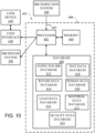
- the system 280 includes an inspection system 285, an analysis system 600, and a repair system 290.
- the present disclosure is not limited in this regard.
- the system 280 may include a single processor, a single memory, and a single user interface and still remain within the scope of this disclosure.
- inspection system 285 and repair system 290 are illustrated as separate systems with separate processors, memories and user interfaces, the present disclosure is not limited in this regard.
- the inspection system 285 and the repair system 290 may be combined into a single system that communicates with the analysis system 600, in accordance with various embodiments.
- the analysis system 600 may include one or more processors 602.
- the analysis system 600 may be configured to process a significant amount of data during an analysis step as described further herein.
- the analysis system 600 may be configured for remote computing (e.g., cloud-based computing), or the like.
- remote computing e.g., cloud-based computing
- a processing time and a volume of data analyzed may be greatly increased relative to typical repair systems, in accordance with various embodiments.
- the inspection system 285, the analysis system 600, and the repair system 290 each include a computer system comprising a processor (e.g., processor 286, processor(s) 602, and/or processor 292) and a memory (e.g., memory 287, memory 604, memory 294).
- the inspection system 285 and the repair system 290 may each comprise a user interface (UI) (e.g., UI 288, UI 296).
- UI user interface
- the inspection system 285 and the repair system 290 may utilize a single user interface to control both systems. The present disclosure is not limited in this regard.
- the analysis system 600 may further comprise a database 606.
- the database 606 comprises various stored data for use in the analysis system 600.
- the database 606 may include an inspected IBR database (e.g., with data from various prior inspected IBRs), a repair data database (e.g., with data from various prior repairs performed / approved), a load data database (e.g., with engine load data from structural and/or aerodynamic analysis), a test data database (e.g., with engine specific test data used for validation of structural and/or aerodynamic analysis), a design data database (e.g., with design models having nominal dimensions according to a product definition of the IBR 100), and/or a material data database (e.g., with material for each component utilized in an analysis step), in accordance with various embodiments.
- an inspected IBR database e.g., with data from various prior inspected IBRs
- a repair data database e.g., with data from various prior repairs performed / approved
- a load data database e.
- System 280 may be configured for inspecting, analyzing, and repairing an IBR 100, in accordance with various embodiments.
- a repair process for an IBR 100 may be fully automated, or nearly fully automated, in accordance with various embodiments, as described further herein.
- systems 285, 600, 290 may each store a software program configured to perform the methods described herein in a respective memory 287, 604, 294 and run the software program using the respective processor 286, 602, 292.
- the systems 285, 600, 290 may include any number of individual processors 286, 602, 292 and memories 287, 604, 294.
- Various data may be communicated between the systems 285, 600, 290 and a user via the user interfaces (e.g., UI 288, UI 296).
- Such information may also be communicated between the systems 285, 600, 290 and external devices, database 606, and/or any other computing device connected to the systems 285, 600, 290 (e.g., through any network such as a local area network (LAN), or wide area network (WAN) such as the Internet).
- LAN local area network
- WAN wide area network
- each processor 286, 602, 292 may retrieve and executes instructions stored in the respective memory 287, 604, 294 to control the operation of the respective system 285, 600, 290.
- Any number and type of processor(s) e.g., an integrated circuit microprocessor, microcontroller, and/or digital signal processor (DSP)
- DSP digital signal processor
- the processor 286, 602, 292 may include, and/or operate in conjunction with, any other suitable components and features, such as comparators, analog-to-digital converters (ADCs), and/or digital-to-analog converters (DACs).
- Functionality of various embodiments may also be implemented through various hardware components storing machine-readable instructions, such as application-specific integrated circuits (ASICs), field-programmable gate arrays (FPGAs) and/or complex programmable logic devices (CPLDs).
- ASICs application-specific integrated circuits
- FPGAs field-programmable gate arrays
- CPLDs complex programmable logic devices
- the memory 287, 604, 294 may include a non-transitory computer-readable medium (such as on a CD-ROM, DVD-ROM, hard drive or FLASH memory) storing computer-readable instructions stored thereon that can be executed by the processor 286, 602, 292 to perform the methods of the present disclosure.
- the memory 287, 604, 294 may include any combination of different memory storage devices, such as hard drives, random access memory (RAM), read only memory (ROM), FLASH memory, or any other type of volatile and/or nonvolatile memory.
- the system 285, 290 may receive and display information via a respective user interface (e.g., UI 288 and/or UI 296).
- the user interfaces e.g., UI 288 and/or UI 296) include various peripheral output devices (such as monitors and printers), as well as any suitable input or control devices (such as a mouse and keyboard) to allow users to control and interact with the software program.
- a user interface for the analysis system 600 can have a user interface to facilitate load inputs, retrieval of information from the inspection system 285, or the like.
- inspection system 285 and repair system 290 may each be in electronic communication with analysis system 600, directly or via a respective user interface (e.g., UI 288 and/or UI 296).
- inspection system 285 and repair system 290 may comprise any suitable hardware, software, and/or database components capable of sending, receiving, and storing data.
- inspection system 285 and/or repair system 290 may comprise a personal computer, personal digital assistant, cellular phone, smartphone (e.g., those running UNIX-based and/or Linux-based operating systems such as IPHONE ® , ANDROID ® , and/or the like), IoT device, kiosk, and/or the like.
- Inspection system 285 and/or repair system 290 may comprise an operating system, such as, for example, a WINDOWS ® mobile operating system, an ANDROID ® operating system, APPLE ® IOS ® , a LINUX ® operating system, and the like. Inspection system 285 and/or repair system 290 may also comprise software components installed on inspection system 285 and/or repair system 290 and configured to enable access to various system 280 components.
- an operating system such as, for example, a WINDOWS ® mobile operating system, an ANDROID ® operating system, APPLE ® IOS ® , a LINUX ® operating system, and the like.
- Inspection system 285 and/or repair system 290 may also comprise software components installed on inspection system 285 and/or repair system 290 and configured to enable access to various system 280 components.
- inspection system 285 and/or repair system 290 may comprise a web browser (e.g., MICROSOFT INTERNET EXPLORER ® , GOOGLE CHROME ® , APPLE SAFARI ® etc.), an application, a micro-app or mobile application, or the like, configured to allow the inspection system 285 and/or repair system 290 to access and interact with analysis system 600 (e.g., directly or via a respective UI, as discussed further herein).
- a web browser e.g., MICROSOFT INTERNET EXPLORER ® , GOOGLE CHROME ® , APPLE SAFARI ® etc.
- analysis system 600 e.g., directly or via a respective UI, as discussed further herein.
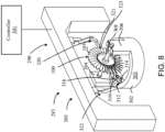
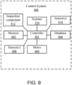
- FIGs. 8 and 9 a perspective view of a system 285 for use in an inspection step 202 and/or a repair step 214 of process 200 ( FIG. 8 ) and a control system 400 for the inspection system 285 ( FIG. 9 ) are illustrated in accordance with various embodiments.
- the system 285 comprises a repair system 290 and an inspection system 285.
- various components of the system 285 may be configured to inspect the IBR 100 and generate a digital map of the IBR 100 (e.g., a point cloud), the inspection system 285 may be configured to transmit the digital map to an analysis system (e.g., analysis system 600), the inspection system 285 may then receive the results from the analysis system 600, and/or perform a repair based on a determination from the analysis system 600, in accordance with various embodiments.
- a digital map of the IBR 100 e.g., a point cloud
- an analysis system e.g., analysis system 600
- the inspection system 285 may then receive the results from the analysis system 600, and/or perform a repair based on a determination from the analysis system 600, in accordance with various embodiments.
- the inspection system 285 comprises a controller 301, a support structure 302, a shaft 308, and a scanner 310.
- the control system 400 comprises the controller 301, the scanner 310, a memory 402, a motor 404, a database 406, and sensor(s) 408, sensor(s) 410, and inspection component 412.
- the inspection system 285 comprises a device 305 configured for bladed rotor repair and/or bladed rotor inspection.
- the support structure 302 comprises a base 303, a first vertical support 304, a second vertical support 306.
- the base 303 may be annular in shape. Although illustrated as being annular, the present disclosure is not limited in this regard.
- the base 303 may be semi-annular in shape, a flat plate, or the like.
- the vertical supports 304, 306 extend vertically upward from the base 303 on opposite sides of the base (e.g., 180 degrees apart, or opposite sides if the base 303 where a square plate).
- the shaft 308 extends from the first vertical support 304 to the second vertical support 306.
- the shaft 308 may be rotatably coupled to the motor 404, which may be disposed within the first vertical support 304, in accordance with various embodiments.
- the shaft 308 may be restrained vertically and horizontally at the second vertical support 306 but free to rotate relative to the second vertical support about a central longitudinal axis of the shaft 308.
- a bearing assembly may be coupled to the second vertical support 306 to facilitate rotation of the shaft, in accordance with various embodiments.
- the IBR 100 to be inspected in accordance with the inspection step 202 of the process 200 via the inspection system 285 may be coupled to the shaft 308 (e.g., via a rigid coupling, or the like).
- the shaft 308 may be coupled to the IBR 100 to be inspected by any method known in the art and be within the scope of this disclosure.
- the scanner 310 is operably coupled to a track system 312.
- the track system 312 may comprise a curved track 314 and a vertical track 316.
- the vertical track 316 may slidingly couple to the vertical track 316 (e.g., via rollers or the like).
- the scanner 310 may be slidingly coupled to the vertical track 316 (e.g., via a conveyor belt, linkages, or the like).
- the scanner 310 is configured to extend from the track system 312 towards the IBR 100 during inspection of the IBR 100 in accordance with step 202 of the process 200.
- the inspection system 285 may further comprise a control arm 322 (e.g., a robot arm), an actuator (e.g., in combination with the track system 312) or the like.
- a control arm 322 e.g., a robot arm
- an actuator e.g., in combination with the track system 312 or the like.
- tracks 314, 316. a control arm 322, and/or an actuator of track system 312 the present disclosure is not limited in this regard.
- any electronically controlled (e.g., wireless or wired) component configured to move the scanner 310, a machining tool (e.g., a mill, a cutter, a lathe, etc.), or the like in six degrees of freedom relative to the IBR 100 is within the scope of this disclosure.
- the inspection component 412 comprises rollers for the curved track, a conveyor belt for the vertical track, and/or a robotic arm coupled to the scanner 310.
- the inspection component 412 comprises only a control arm 322 (e.g., a robot arm).
- the inspection component 412 comprises only the rollers for the curved track 314 and the conveyor belt or linkages for the vertical track 316.
- the inspection component 412 is stationary and the IBR 100 being inspected is moveable along three-axis, five-axis, or the like. The present disclosure is not limited in this regard.
- the scanner 310 comprises a coordinate measuring machine (CMM), a mechanical scanner, a laser scanner, a structured scanner (e.g., a white light scanner, a blue light scanner, etc.), a non-structured optical scanner, a non-visual scanner (e.g., computed tomography), or the like.
- the scanner 310 is a blue light scanner.
- the scanner 310 may be swapped with another scanner at any point during an inspection step 202 as described further herein.
- the inspection system 285 may be configured to swap the scanner 310 with a different scanner during the inspection step 202 of process 200 as described further herein.
- a "blue light scanner” as disclosed herein refers to a non-contact structure light scanner.
- the blue light scanner may have a scan range of between 100 ⁇ 75 mm 2 - 400 x 300 mm 2 , in accordance with various embodiments.
- an accuracy of the blue light scanner may be between 0.005 and 0.015 mm.
- the blue light scanner be able to determine distances between adjacent points in the point cloud of between 0.04 and 0.16 mm as measured across three axes.
- a volume accuracy of the blue light scanner may be approximately 0.8 mm/m.
- a scan depth may be between approximately 100 and 400 mm.
- the blue light scanner may comprise a light source including a blue LED.
- the blue light scanner may be configured to emit an average wavelength between 400 and 450 nm, in accordance with various embodiments. Although described with various specifications herein, the blue light scanner is not limited in this regard, and one skilled in the art may recognize the parameters of the blue light scanner may extend outside the exemplary ranges. Use of a blue light scanner provides a high resolution point cloud for a three dimensional object.
- the inspection system 285 further comprises a control arm 320 of the repair system 290.
- the control arm 320 comprises a tool holder 321.
- the tool holder 321 is configured to couple to a subtractive component 323 (e.g., a mill, a lathe, a cutter, etc.).
- the control arm 322 of inspection system 285 may be a control arm for the repair system 290 as well.
- the control arms 320, 322 may be used in both the repair system 290 and the inspection system 285. The present disclosure is not limited in this regard.
- the controller 301 may be integrated into computer system of the inspection system 285 (e.g., in processor 286 and/or memory 287 from FIG. 2B). In various embodiments, the controller 301 may be configured as a central network element or hub to various systems and components of the control system 400. In various embodiments, controller 301 may comprise a processor (e.g., processor 286). In various embodiments, controller 301 may be implemented as a single controller (e.g., via a single processor 286 and associated memory 287). In various embodiments, controller 301 may be implemented as multiple processors (e.g., a main processor and local processors for various components).
- the controller 301 can be a general purpose processor, a digital signal processor (DSP), an application specific integrated circuit (ASIC), a field programable gate array (FPGA) or other programable logic device, discrete gate or transistor logic, discrete hardware components, or any combination thereof.
- the controller 301 may comprise a processor configured to implement various logical operations in response to execution of instructions, for example, instructions stored on a non-transitory, tangible, computer-readable medium configured to communicate with the controller 301.
- System program instructions and/or controller instructions may be loaded onto a non-transitory, tangible computer-readable medium having instructions stored thereon that, in response to execution by a controller, cause the controller to perform various operations.
- the term "non-transitory” is to be understood to remove only propagating transitory signals per se from the claim scope and does not relinquish rights to all standard computer-readable media that are not only propagating transitory signals per se. Stated another way, the meaning of the term “non-transitory computer-readable medium” and “non-transitory computer-readable storage medium” should be construed to exclude only those types of transitory computer-readable media which were found in In Re Nuijten to fall outside the scope of patentable subject matter under 35 U.S.C. ⁇ 101.
- the motor 404 of the control system 400 is operably coupled to the shaft 308 of the control system 400.
- the motor 404 may comprise a direct current (DC) stepper, an alternating current (AC) motor or the like.
- the sensor(s) 408 include Hall effect sensor(s), optical sensor(s), resolver(s), or the like.
- sensor(s) 408 may include sensor(s) configured to detect an angular position of the shaft 308 during an inspection step for an IBR 100 (e.g., step 202 from the process 200). In this regard, during inspection of the IBR 100, the controller 301 receives sensor data from the sensor(s) 408.
- the controller 301 can utilize the sensor data received from the sensor(s) 408 to correlate an angular position of the IBR 100 being inspected with a location of the scanner 310 as described further herein.
- the IBR 100 may remain stationary throughout an inspection process (e.g., inspection step 202 of process 200) and only a control arm (e.g., control arm 320 and/or control arm 322) may move.
- coordinates of the control arm(s) may be determined via sensor(s) 408 in a similar manner to orient and construct the IBR 100 being inspected.
- the sensor(s) 410 are configured to detect a position of the scanner 310 during the inspection step 202 of process 200.
- sensor(s) 410 may be position sensors (e.g., capacitive displacement sensors, eddy-current sensors, Hall effect sensors, inductive sensors, optical sensors, linear variable differential transformer (LVDT) sensors, photodiode array sensors, piezoelectric sensors, encoders, potentiometer sensors, ultrasonic sensors or the like).
- position sensors e.g., capacitive displacement sensors, eddy-current sensors, Hall effect sensors, inductive sensors, optical sensors, linear variable differential transformer (LVDT) sensors, photodiode array sensors, piezoelectric sensors, encoders, potentiometer sensors, ultrasonic sensors or the like.
- controller 301 is able to determine a location of the scanner 310 and an angular position of the IBR 100 throughout the inspection.
- a digital map (e.g., a robust point cloud) can be generated during the inspection step 202 of process 200 for the IBR 100 being inspected.
- the point cloud encompasses the entire IBR 100 (e.g., between 95% and 100% of a surface area of the IBR 100, or between 99% and 100% of the surface area of the IBR 100).
- an analysis system 600 for use in an inspection, analysis, and repair process (e.g., process 200 from FIG. 6 ) as described previously herein is illustrated, in accordance with various embodiments.
- the analysis system 600 comprises the processor 602, the memory 604, and the database 606 from FIG. 7 .
- the analysis system 600 is a computer-based system.
- the system 600 is a cloud-based computing system.
- the analysis system 600 comprises a machine learning system 601 (e.g., a deep neural network (DNN), an artificial neural network (ANN), or the like).
- DNN deep neural network
- ANN artificial neural network
- the analysis system 600 described herein can be configured for machine learning to constantly expand experience based criteria of step 212 in process 200 via step 220 as described previously herein.
- the processor 602 is configured to receive an input 603 from the inspection system 285 (e.g., via the control system 400 from FIG. 7 ).
- the input 603 can comprise, a point cloud, a three-dimensional model, two-dimensional section models, a text file of coordinates of an IBR 100 inspected in accordance with the process described further herein.
- the processor 602 in response to receiving the input 603, is configured to generate a digital model for evaluations (e.g., as outlined in steps 210, 228 from process 200).
- the analysis system 600 may include a port configured to couple to a hard drive, or any other device configured to transfer data obtained from inspecting the IBR 100 in step 202 of process 200.
- the processor 602 may be in direct electronic (e.g., wireless or wired) communication with the inspection system 285 from step 202 of process 200.
- the processor 602 is configured to communicate with the IBR inspection system over a network, or the like. The present disclosure is not limited in this regard.
- the processor 602 is in communication with a user interface ("UI") 630, which includes a user device 640.
- the analysis system 600 can be configured for determining a repaired IBR 170, 171 having repair blend profiles 160 as shown in FIGs. 5A-E , in accordance with various embodiments.
- the processor 602 of the analysis system 600 is configured to receive an input 603 (e.g., from the inspection system 285 of step 202 in process), perform various simulations and/or evaluations (e.g., in steps 210, 228), and output at the repair blend profiles 160 for respective defects 140 of the IBR 100.
- the analysis system 600 may be configured to perform simulations based on the stack of IBRs 110 from FIG.
- Each IBR in the stack of IBRs 110 can be an IBR 100 that was inspected in step 202 of process 200.
- a higher fidelity analysis can be performed in step 210 or step 228 at a system level for IBR that don't meet the experience based criteria in step 212 but could meet the deterministic criteria in step 230 based on a modification of an IBR 100 in the stack of IBRs 110.
- the input 603 may comprise a digital representation for each IBR 100 in a stack of IBRs 110 from FIG. 1B that have been inspected in accordance with process 200, in accordance with various embodiments.
- the database 606 includes an inspected IBR database 612 including available IBRs 100 for use in a stack of IBRs 110.
- the analysis system 600 may be configured to mix and match IBRs 100, which were on different gas turbine engines 20 from FIG. 1A previously, based on an optimal repair process, in accordance with various embodiments.
- the analysis system 600 may store a software program configured to perform the methods described herein in the memory 604 and run the software program using the processor 602.
- the analysis system 600 may include any number of individual processors 602 and memories 604.
- Various data may be communicated between the analysis system 600 and a user via the UI 630 and/or the inspection system 285.
- Such information may also be communicated between the analysis system 600 and any other external devices (e.g., a computer numerical control (CNC) machine, an additive manufacturing machine, such as a directed energy deposition (DED) machine, etc.), and/or any other computing device connected to the analysis system 600 (e.g., through any network such as a local area network (LAN), or wide area network (WAN) such as the Internet).
- CNC computer numerical control
- DED directed energy deposition
- the processor 602 of the analysis system 600 retrieves and executes instructions stored in the memory 604 to control the operation of the analysis system 600.
- the database 606 comprises various stored data for use in the analysis system 600 as described further herein.
- the database 606 may include an inspected IBR database 612, a repair data database 614, a load data database 616, a test data database 618, a design data database 620, and/or a material data database 622, in accordance with various embodiments.
- the inspected IBR database 612 comprises a digital representation of inspected IBRs 100 with or without potential repair shapes modeled therein and received from the inspection system 285 that are awaiting repair in step 214 of the process 200.
- the inspected IBR database 612 may include unrepaired IBRs 100 for use in the simulation and analysis steps of process 200 (e.g., steps 210 and/or 228).
- steps 210 and/or 2208 Although described herein as including the inspected IBR database 612, the present disclosure is not limited in this regard.
- repair options may be determined for an IBR 100 individually without analysis related to other IBRs 100 in the stack of IBRs 110 from FIG. 1B , in accordance with various embodiments.
- repair options may be determined for one or more blades 103 of an IBR 100 individually without analysis related to other blades 103 for the IBR 100, in accordance with various embodiments.
- more optimal repair options may be determined (e.g., based on cost, time, amount of material removed, etc.)
- an IBR 100 which may have had a previously unrepairable airfoil determined at a blade level may be repairable based on a component level or module level analysis, and/or blending an airfoil without a defect to offset module or component level effects (e.g., mistuning, aerodynamic capability, etc.), in accordance with various embodiments.
- the repair data database 614 includes previously performed repairs (e.g., blend shapes, additive repair shapes, etc.).
- the repair data database 614 may include any structural debits, aerodynamic debits or the like associated with the previously performed repairs for other IBRs (i.e., not the IBR being inspected).
- the repair data database may become more robust, improving the analysis system 600 the more the analysis system 600 is utilized, in accordance with various embodiments.
- the load data database 616 comprises boundary conditions for the gas turbine engine 20 for use in structural analysis and aerodynamic analysis as described further herein.
- the boundary conditions may include temperature (i.e., highest expected blade temperature, lowest expected blade temperature, etc.), rotor speed (e.g., max rotor speed, typical rotor speed, rotor speed as a function of flight cycle, etc., rotor speed generating modal response, etc.), or any other boundary condition for the IBR 100, the stack of IBRs 110, or the high pressure compressor 52.
- module level boundary conditions may include stack stiffness, clocking, clearances (cases, tips, back-bone bending, etc.), blade counts, axial gapping, imbalance, secondary flow influence, or the like.
- the test data database 618 includes engine test data associated with the IBR 100, the stack of IBRs 110, and/or the rotor module 111. For example, prior to certifying a gas turbine engine 20 from FIG. 1A for production, assumptions with respect to structural analysis performed during a design stage of development may be validated and verified through engine testing. During engine testing, strain gauges may be coupled in various locations on an IBR 100 (e.g., expected high stress locations based on the structural analysis). In response to receiving strain gauge data from the engine testing, analytical or predicted results from the structural analysis can be scaled using actual or measured results to correlate the model to actual data from the engine testing. Thus, the test data database 618 comprises actual test data to be used for scaling predicted data of the analysis system 600 during processes described further herein.
- the design data database 620 comprises three-dimensional models of surrounding components (e.g., blade stages 101, exit guide vane stage 106, outer engine case 120, etc.).
- the analysis system 600 may be configured to prepare a structural model (e.g., via ANSYS, ANSYS Workbench, etc.) and/or a computational fluid dynamics (CFD) model with the surrounding components and the input 603 received from the inspection system 285 and run various simulations with various repair options to determine an optimal repair for an IBR 100, for each IBR 100 in a stack of IBRs 110, or for matching repairs of IBRs 100 for various performance parameters (e.g., aerodynamic operability, mistuning, etc.).
- a structural model e.g., via ANSYS, ANSYS Workbench, etc.
- CFD computational fluid dynamics
- the design data database further comprises an original design of the IBR being inspected.
- an original three-dimensional model of the IBR 100 being inspected with nominal dimensions i.e., nominal in accordance with a product definition of the IBR, in accordance with various embodiments.
- the material data database 622 comprises material data corresponding to a material of the IBR 100.
- the IBR 100 is made of an iron-based alloy (e.g., stainless steel), nickel-based alloy, a titanium alloy, or the like. The present disclosure is not limited in this regard.
- material properties for the material the IBR 100 is made of are stored in the material data database 622.
- the empirical results may be compared to a threshold zone of acceptance (e.g., a Goodman diagram with steady state stress compared to vibratory stress), where the threshold zone of acceptance is based on the material properties and a margin of safety, in accordance with various embodiments.
- a threshold zone of acceptance e.g., a Goodman diagram with steady state stress compared to vibratory stress
- the processor 602 may output at least one repair process for a respective IBR 100 to the user device (e.g., through the UI 630, directly to the user device 640, or the like).
- the output may comprise manual instructions for a blend repair process, a computer numerical control ("CNC") machining process (e.g., blending or the like).
- the processor 602 sends CNC machining instructions to the repair system 290 directly, and the repair system 290 repairs the IBR 100 to generate a repaired IBR 170 from FIG. 5A , in accordance with various embodiments.
- the database 606 includes an inspected IBR database 612 including available IBRs 100 for use in a stack of IBRs 110 (i.e., as determined in step 232 of process 200).
- the analysis system 600 may be configured to mix and match IBRs 100, which were on different gas turbine engines 20 from FIG. 1A previously, based on IBRs 100 not meeting deterministic criteria at a component level, in accordance with various embodiments.
- the analysis system 600 may store a software program configured to perform the methods described herein in the memory 604 and run the software program using the processor 602.
- the analysis system 600 may include any number of individual processors 602 and memories 604.
- Various data may be communicated between the analysis system 600 and a user via the UI 630 and/or the inspection system 285.
- Such information may also be communicated between the analysis system 600 and any other external devices (e.g., a computer numerical control (“CNC") machine, etc.), and/or any other computing device connected to the analysis system 600 (e.g., through any network such as a local area network (LAN), or wide area network (WAN) such as the Internet).
- LAN local area network
- WAN wide area network
- the processor 602 of the analysis system 600 retrieves and executes instructions stored in the memory 604 to control the operation of the analysis system 600.
- the database 606 comprises various stored data for use in the analysis system 600 as described further herein.
- the database 606 may include an inspected IBR database 612, a repair data database 614, a load data database 616, a test data database 618, a design data database 620, a material data database 622, and/or a quality data database 624 in accordance with various embodiments.
- the inspected IBR database 612 comprises a digital representation of inspected IBRs 100 received from the inspection system 285 that are awaiting repair in step 214 of process 200 or did not meet deterministic criteria in step 230 of process 200.
- the inspected IBR database 612 may include unrepaired IBRs 100 for use in system level analysis of a stack of IBRs 110, in accordance with various embodiments.
- inspected IBRs that would otherwise be scrapped could potentially be combined in a stack of IBRs to meet satisfy structural criteria and system level aerodynamic criteria, in accordance with various embodiments.
- the repair data database 614 includes previously performed repairs (e.g., blend shapes).
- the repair data database 614 may include any structural debits, aerodynamic debits or the like associated with the previously performed repairs for other IBRs (i.e., not the IBR being inspected). As such, as more repairs are determined, performed, and tested, the repair data database may become more robust, improving the analysis system 600 the more the analysis system 600 is utilized, in accordance with various embodiments.
- the load data database 616 comprises boundary conditions for the gas turbine engine 20 for use in structural analysis and aerodynamic analysis as described further herein.
- the boundary conditions may include temperature (i.e., highest expected blade temperature, lowest expected blade temperature, etc.), rotor speed (e.g., max rotor speed, typical rotor speed, rotor speed as a function of flight cycle, etc., rotor speed generating modal response, etc.), or any other boundary condition for the IBR 100, the stack of IBRs 110, or the high pressure compressor 52.
- module level boundary conditions may include stack stiffness, clocking, clearances (cases, tips, back-bone bending, etc.), blade counts, axial gapping, imbalance, secondary flow influence, or the like.
- the test data database 618 includes engine test data associated with the IBR 100, the stack of IBRs 110, and/or the rotor module 111. For example, prior to certifying a gas turbine engine 20 from FIG. 1A for production, assumptions with respect to structural analysis performed during a design stage of development may be validated and verified through engine testing. During engine testing, strain gauges may be coupled in various locations on an IBR 100 (e.g., expected high stress locations based on the structural analysis). In response to receiving strain gauge data from the engine testing, analytical or predicted results from the structural analysis can be scaled using actual or measured results to correlate the model to actual data from the engine testing. Thus, the test data database 618 comprises actual test data to be used for scaling predicted data of the analysis system 600 during processes described further herein.
- the design data database 620 comprises three-dimensional models of surrounding components (e.g., blade stages 101, exit guide vane stage 106, outer engine case 120, etc.).
- the analysis system 600 may be configured to prepare a structural model (e.g., via ANSYS, ANSYS Workbench, etc.) and/or a computational fluid dynamics (CFD) model with the surrounding components and the input 603 received from the inspection system 285 and run various simulations with various repair options to determine an optimal repair for an IBR 100, for each IBR 100 in a stack of IBRs 110, or for matching repairs of IBRs 100 for various performance parameters (e.g., aerodynamic operability, mistuning, etc.) (i.e., for component level analysis in evaluation steps 210, 228, and/or for system level analysis performed in evaluation steps 210, 228 in process 200).
- a structural model e.g., via ANSYS, ANSYS Workbench, etc.
- CFD computational fluid dynamics
- the design data database further comprises an original design of the IBR being inspected.
- an original three-dimensional model of the IBR 100 being inspected with nominal dimensions i.e., nominal in accordance with a product definition of the IBR, in accordance with various embodiments.
- the material data database 622 comprises material data corresponding to a material of the IBR 100.
- the IBR 100 is made of an iron-based alloy (e.g., stainless steel), nickel-based alloy, a titanium alloy, or the like. The present disclosure is not limited in this regard.
- material properties for the material the IBR 100 is made of are stored in the material data database 622.
- the empirical results may be compared to a threshold zone of acceptance (e.g., a Goodman diagram with steady state stress compared to vibratory stress), where the threshold zone of acceptance is based on the material properties and a margin of safety, in accordance with various embodiments.
- a threshold zone of acceptance e.g., a Goodman diagram with steady state stress compared to vibratory stress
- the quality data database 624 comprises quality data associated with various quality information / dispositions for a known defect shapes, sizes, etc.
- quality data e.g., an estimated remaining life, or the like
- historical quality data can be utilized by the analysis system 600 for making dispositions and determinations for an inspected IBR as described further herein, in accordance with various embodiments.
- the process 1100 can be performed by an inspection system (e.g., inspection system 285 from FIGs. 7 and 8 ), a combined inspection and repair system (e.g., inspection system 285 and repair system 290 combined), or the like.
- the process 1100 is configured for facilitating fast and/or efficient transfer of relevant inspection data from an inspection system 285 to an analysis system 600 (e.g., a cloud-based computing system or remote computing system configured for significantly greater processing power).
- the inspection system 285 can be installed at overhaul and/or maintenance facilities and communicate relevant inspection data with an analysis system in a remote (or cloud-based) location to perform structural and/or aerodynamic simulations to determine acceptability, and the analysis system can transmit a result back to the inspection system 285 (and/or repair system 290 as described further herein.
- the process 1100 comprises receiving, via a processor (e.g., the processor 286 of FIG. 7 ), scanner data (e.g., from the scanner 310) of an inspected bladed rotor (e.g., IBR 100 from FIG. 7 ).
- scanner data e.g., from the scanner 310
- an inspected bladed rotor e.g., IBR 100 from FIG. 7
- blue light scanners can be accurate up to 0.0001 inches (0.00025 cm) (i.e., have a corresponding data point in a point cloud for every 0.0001 inch of a surface).
- 10 square inches (64.5 square centimeters) of surface area can correspond to approximately 1 billion data points in a point cloud generated by a scanner 310 of inspection system 285, in accordance with various embodiments.
- the process 1100 further comprises, generating, via the processor, a data set from the scanner data of the inspected bladed rotor for transfer (step 1104).
- the data set generated in step 1104 can be configured to greatly reduce a file size (i.e., by several orders of magnitude) compared to a file size of the scanner data alone.
- the point cloud generated from the scanner 310 can be compared to an ideal model (i.e., a design model), of a bladed rotor and any discrepancies between the ideal model and the point cloud can be included in the data set of step 1104.
- the point cloud 1202 of a blade 1201 of an inspected IBR 1200 can be reduced to section files 1210 (i.e., files defining a perimeter of a radial cross-section of a blade 103 of an IBR 100 at various spans along a blade 103)
- section files 1210 i.e., files defining a perimeter of a radial cross-section of a blade 103 of an IBR 100 at various spans along a blade 103
- section files can be created at various intervals such as every 0.1 inches (0.254 cm), 0.25 inches (0.635 cm), 0.5 inches (1.27 cm), 1 inch (2.54 cm), or the like.
- the section files can greatly reduce a size of the data (e.g., 2500 times for 0.25 inch (0.635) intervals, 10,000 times for 1 inch (2.54 cm) intervals, etc.) and still provide a general contour of the blade 103 of the inspected IBR 100.
- the process 1100 can generate a file size that is between 10 times and 1,000,000 times smaller relative to a file size of a point cloud generated from a scanner 310 of the inspection system 285, or between 100 times and 100,000 smaller, or between 1,000 times and 100,000 times smaller, in accordance with various embodiments.
- a smaller interval between section files can be created at a defect location 1204.
- section files 1210 can generally be spaced apart by an inch (2.54 cm), and then spaced apart by 0.25 inches (0.635 cm) at a defect location.
- an ideal IBR e.g., an IBR corresponding to nominal design data.
- the processor 286 of the inspection system 285 can transform the point cloud to have the initial blend profiles (e.g., in the defect location 1204) prior to generating section files 1210 in accordance with FIG. 12A .
- the processor, 286 can generate relatively smooth section files (even in a defect location 1204) that can easily be imported into a simulation (e.g., a structural simulation and/or an aerodynamic simulation) without causing any errors in the simulation.
- the initial blend profiles can be created in accordance with step 208 of FIG. 6 .
- either the point cloud (or the section files) can be compared to an ideal bladed rotor (e.g., a design model bladed rotor based on nominal dimensions of the bladed rotor for manufacture) to determine if any defects meet serviceable limits prior to modeling an initial blend.
- an ideal bladed rotor e.g., a design model bladed rotor based on nominal dimensions of the bladed rotor for manufacture
- even defects that meet serviceable limits can still be modeled as being relatively smooth to facilitate ease of simulation (e.g., preventing errors due to sharp edges in a finite element model, or the like) in the analysis system 600 after transfer of the data file.
- the reduced data set generated from the process 1100 can have even less data associated with a defect location and still be within the scope of this disclosure.
- a data point 1220 can correspond to a defect location (e.g., a maximum defect depth, an interpolated point along an airfoil surface, or the like). Included with the data point 1220, in the reduced data set, details of the respective blend profile can be transmitted (e.g., an initial blend profile to repair the defect at the data point 1220).
- blend profile details can include a blend depth, a radius of curvature, a blend length, a blend width, a blend aspect ratio, etc. Any blend detail is within the scope of this disclosure.
- the analysis system can take the data point 1220 with the respective defect details and modify (or transform) a digital representation of an ideal bladed rotor as described further herein.
- the process 1100 further comprises transmitting, via the processor, the reduced data set from the inspection system to an analysis system (e.g., analysis system 600).
- the reduced data set can be small enough in size to be transferred easily and/or quickly from the inspection system 285 (e.g., through any network such as a local area network (LAN), or wide area network (WAN) such as the Internet) to the analysis system 600.
- LAN local area network
- WAN wide area network
- the simulations can be performed.
- a result or disposition
- the disposition can include a location of a defect, a repair blend profile for the defect, etc. If the system is an inspection system 285 and a repair system 290, the system can automatically perform the repair. In various embodiments, the disposition can include holding the inspected bladed rotor for later use (e.g., due to a defect being too large at a given point in time). In this regard, after additional learning from the processes disclosed herein, a blend profile corresponding to the inspected bladed rotor that was held may be deemed acceptable, at which time the repair blend can be performed.
- references to "one embodiment,” “an embodiment,” “various embodiments,” etc. indicate that the embodiment described may include a particular feature, structure, or characteristic, but every embodiment may not necessarily include the particular feature, structure, or characteristic. Moreover, such phrases are not necessarily referring to the same embodiment. Further, when a particular feature, structure, or characteristic is described in connection with an embodiment, it is submitted that it is within the knowledge of one skilled in the art to affect such feature, structure, or characteristic in connection with other embodiments whether or not explicitly described. After reading the description, it will be apparent to one skilled in the relevant art(s) how to implement the disclosure in alternative embodiments.
- Numbers, percentages, or other values stated herein are intended to include that value, and also other values that are about or approximately equal to the stated value, as would be appreciated by one of ordinary skill in the art encompassed by various embodiments of the present disclosure.
- a stated value should therefore be interpreted broadly enough to encompass values that are at least close enough to the stated value to perform a desired function or achieve a desired result.
- the stated values include at least the variation to be expected in a suitable industrial process, and may include values that are within 10%, within 5%, within 1%, within 0.1%, or within 0.01% of a stated value.
- the terms “substantially,” “about” or “approximately” as used herein represent an amount close to the stated amount that still performs a desired function or achieves a desired result.
- the term “substantially,” “about” or “approximately” may refer to an amount that is within 10% of, within 5% of, within 1% of, within 0.1 % of, and within 0.01% of a stated amount
Abstract
A method can comprise: receiving an inspection data corresponding to a geometry of an inspected bladed rotor (131); performing a baseline evaluation based on the inspection data; determining a plurality of candidate repair profiles (160) for a defect of the inspected bladed rotor (131); performing an updated evaluation for each candidate repair profile in the plurality of candidate repair profiles (160); selecting a selected candidate repair profile in the plurality of candidate repair profiles (160) based on the updated evaluation for each candidate repair profile in the plurality of candidate repair profiles (160); and performing a repair based on the selected candidate repair profile.
Description
- The present disclosure relates to repair analysis methods and systems, and more particularly, the repair analysis systems and methods for bladed rotors of gas turbine engines.
- Gas turbine engines (such as those used in electrical power generation or used in modern aircraft) typically include a compressor, a combustor section, and a turbine. The compressor and the turbine typically include a series of alternating rotors and stators. A rotor generally comprises a rotor disk and a plurality of blades. The rotor may be an integrally bladed rotor ("IBR") or a mechanically bladed rotor.
- The rotor disk and blades in the IBR are one piece (i.e., monolithic, or nearly monolithic) with the blades spaced around the circumference of the rotor disk. Conventional IBRs may be formed using a variety of technical methods including integral casting, machining from a solid billet, or by welding or bonding the blades to the rotor disk.
- Repair methods for IBRs may be limited to maintaining the IBR within tolerances of a product definition for a design of the IBR, a volume or thickness of material addition, and/or a volume or thickness of material removal. Additionally, repair analysis methods for IBRs may fail to consider loads and/or boundary conditions encountered during engine operation included in the aerodynamic, structural, or other functional assessment of the IBR. In this regard, a damaged IBR may be scrapped because it is believed to unrepairable within the geometric assessment constraints (e.g., tolerances, material removal, material addition, etc.) without consideration of the functional assessment constraints (e.g., aerodynamic stability, structural durability, etc.). By being limited in this manner, less expensive repair options and/or more optimal repairs (e.g., in terms of aerodynamic or structural capability, etc.) that could otherwise be acceptable may be avoided.
- A method is disclosed herein. The method can comprise: receiving an inspection data corresponding to a geometry of an inspected bladed rotor; performing a baseline evaluation based on the inspection data; determining a plurality of candidate repair profiles for a defect of the inspected bladed rotor; performing an updated evaluation for each candidate repair profile in the plurality of candidate repair profiles; selecting a selected candidate repair profile in the plurality of candidate repair profiles based on the updated evaluation for each candidate repair profile in the plurality of candidate repair profiles; and performing a repair based on the selected candidate repair profile.
- In various embodiments, the baseline evaluation and the updated evaluations include an engine performance evaluation, an engine operability evaluation, a module aerodynamic performance evaluation, and a structural evaluation. The method can further comprise balancing output parameters from the updated evaluations prior to selecting the selected candidate repair profile.
- In various embodiments, the plurality of candidate repair profiles includes a repair blend profile and a repair patch profile.
- In various embodiments, the selected candidate repair profile is selected based on an impact to a second inspected bladed rotor based on an output parameter from the updated evaluation.
- In various embodiments, the baseline evaluation and the updated evaluation includes performing a modal analysis, a static analysis, a turning and loss change analysis, and an engine performance analysis.
- In various embodiments, the baseline evaluation includes evaluating a digital representation based on the geometry and an initial repair blend profile.
- An article of manufacture is disclosed herein. In various embodiments, the article of manufacture includes a tangible, non-transitory computer-readable storage medium having instructions stored thereon that, in response to execution by a processor, cause the processor to perform operations comprising: receiving, by the processor, a digital representation of a geometry of an inspected bladed rotor; receiving, by the processor, engine data from a gas turbine engine that had the inspected bladed rotor installed thereon; performing, by the processor, a baseline evaluation of the digital representation based on the digital representation, an initial repair shape, and the engine data; performing, by the processor, an updated evaluation for each candidate repair profile in a plurality of candidate repair profiles for the inspected bladed rotor; and generating, by the processor, results from the updated evaluation for each candidate repair profile.
- In various embodiments, the operations further comprise receiving, by the processor, a candidate repair profile in the plurality of candidate repair profiles based on impacting the updated evaluation for a second inspected bladed rotor for a module level analysis.
- In various embodiments, the baseline evaluation and the updated evaluations include an engine performance evaluation, an engine operability evaluation, a module aerodynamic performance evaluation, and a structural evaluation.
- In various embodiments, the operations further comprise generating, by the processor, shape sensitivity data to a repair shape for the inspected bladed rotor.
- In various embodiments, the operations further comprise determining, by the processor, whether the updated evaluation for each candidate repair profile in the plurality of candidate repair profiles meets an experience based criteria.
- In various embodiments, the operations further comprise determining, by the processor, whether the updated evaluation for each candidate repair profile in the plurality of candidate repair profiles meets a deterministic criteria.
- In various embodiments, the updated evaluation for each candidate repair profile in the plurality of candidate repair profiles includes a module level evaluation including a plurality of inspected bladed rotors.
- A system is disclosed herein. In various embodiments, the system comprises: an inspection system configured to scan an inspected bladed rotor and generate a point cloud of at least a portion of the inspected bladed rotor; and an analysis system in electronic communication with the inspection system, the analysis system comprising a tangible, non-transitory computer-readable storage medium having instructions stored thereon that, in response to execution by a processor, cause the processor to perform operations comprising: receive, by the processor, a data set based on the point cloud; generate, by the processor, a digital representation of the inspected bladed rotor based on the data set; perform, by the processor, a baseline evaluation based on the digital representation; perform, by the processor, an updated evaluation for each candidate repair profile in a plurality of candidate repair profiles; and generate, by the processor, results from the updated evaluation for each candidate repair profile.
- In various embodiments, the baseline evaluation and the updated evaluations include an engine performance evaluation, an engine operability evaluation, a module aerodynamic performance evaluation, and a structural evaluation.
- In various embodiments, the operations further comprise receiving, by the processor, a candidate repair profile in the plurality of candidate repair profiles based on impacting the updated evaluation for a second inspected bladed rotor for a module level analysis.
- In various embodiments, the operations further comprise generating, by the processor, shape sensitivity data to a repair shape for the inspected bladed rotor.
- In various embodiments, the operations further comprise determining, by the processor, whether the updated evaluation for each candidate repair profile in the plurality of candidate repair profiles meets a deterministic criteria.
- In various embodiments, the updated evaluation includes an aerodynamic simulation and a structural simulation.
- The foregoing features and elements may be combined in any combination, without exclusivity, unless expressly indicated herein otherwise. These features and elements as well as the operation of the disclosed embodiments will become more apparent in light of the following description and accompanying drawings.
- The subject matter of the present disclosure is particularly pointed out and distinctly claimed in the concluding portion of the specification. A more complete understanding of the present disclosure, however, may best be obtained by referring to the following detailed description and claims in connection with the following drawings. While the drawings illustrate various embodiments employing the principles described herein, the drawings do not limit the scope of the claims.
-
FIG. 1A illustrates a cross-sectional view of a gas-turbine engine, in accordance with various embodiments; -
FIG. 1B illustrates a cross-sectional view of a high pressure compressor, in accordance with various embodiments; -
FIG. 2 illustrates a front view of a bladed rotor, in accordance with various embodiment; -
FIG. 3 illustrates a portion of an inspected bladed rotor, in accordance with various embodiments; -
FIG. 4 illustrates a portion of the inspected bladed rotor during repair, in accordance with various embodiments; -
FIG. 5A illustrates a portion of a repaired bladed rotor, in accordance with various embodiments; -
FIG. 5B illustrates a repair blend profile, in accordance with various embodiments; -
FIG. 5C illustrates a repair blend profile, in accordance with various embodiments; -
FIG. 5D illustrates a repair blend profile, in accordance with various embodiments; -
FIG. 5E illustrates a repair patch profile, in accordance with various embodiments; -
FIG. 6 illustrates an inspection, analysis, and repair process for a bladed rotor, in accordance with various embodiments; -
FIG. 7 , illustrates a system to perform the inspection, analysis, and repair process ofFIG. 6 , in accordance with various embodiments; -
FIG. 8 illustrates an inspection and/or repair system, in accordance with various embodiments; -
FIG. 9 illustrates a schematic view of a control system for an inspection system, in accordance with various embodiments; -
FIG. 10 illustrates a schematic view analysis system, in accordance with various embodiments; and -
FIG. 11 illustrates a process for reducing a data file size, in accordance with various embodiments; -
FIG. 12A illustrates a point cloud of an inspected bladed rotor, in accordance with various embodiments; -
FIG. 12B illustrates a section file of an inspected bladed rotor, in accordance with various embodiments; and -
FIG. 12C illustrates a section file of an inspected bladed rotor, in accordance with various embodiments. - The following detailed description of various embodiments herein refers to the accompanying drawings, which show various embodiments by way of illustration. While these various embodiments are described in sufficient detail to enable those skilled in the art to practice the disclosure, it should be understood that other embodiments may be realized and that changes may be made without departing from the scope of the disclosure. Thus, the detailed description herein is presented for purposes of illustration only and not of limitation. Furthermore, any reference to singular includes plural embodiments, and any reference to more than one component or step may include a singular embodiment or step. Also, any reference to attached, fixed, connected, or the like may include permanent, removable, temporary, partial, full or any other possible attachment option. Additionally, any reference to without contact (or similar phrases) may also include reduced contact or minimal contact. It should also be understood that unless specifically stated otherwise, references to "a," "an", or "the" may include one or more than one and that reference to an item in the singular may also include the item in the plural. Further, all ranges may include upper and lower values and all ranges and ratio limits disclosed herein may be combined.
- As used herein, "aft" refers to the direction associated with the tail (e.g., the back end) of an aircraft, or generally, to the direction of exhaust of the gas turbine. As used herein, "forward" refers to the direction associated with the nose (e.g., the front end) of an aircraft, or generally, to the direction of flight or motion.
- With reference to
FIG. 1A , agas turbine engine 20 is shown according to various embodiments.Gas turbine engine 20 may be a two-spool turbofan that generally incorporates afan section 22, acompressor section 24, acombustor section 26, and aturbine section 28. In operation,fan section 22 can drive air along a path of bypass airflow B whilecompressor section 24 can drive air along a core flow path C for compression and communication intocombustor section 26 then expansion throughturbine section 28. Although depicted as a turbofangas turbine engine 20 herein, it should be understood that the concepts described herein are not limited to use with turbofans as the teachings may be applied to other types of turbine engines including three-spool architectures, single spool architecture or the like. -
Gas turbine engine 20 may generally comprise alow speed spool 30 and ahigh speed spool 32 mounted for rotation about an engine central longitudinal axis A-A' relative to an enginestatic structure 36 or engine case viaseveral bearing systems 38, 38-1, etc. Engine central longitudinal axis A-A' is oriented in the Z direction on the provided X-Y-Z axes. It should be understood that various bearingsystems 38 at various locations may alternatively or additionally be provided, including for example, bearingsystem 38, bearing system 38-1, etc. -
Low speed spool 30 may generally comprise aninner shaft 40 that interconnects afan 42, alow pressure compressor 44 and alow pressure turbine 46.Inner shaft 40 may be connected to fan 42 through a gearedarchitecture 48 that can drivefan 42 at a lower speed thanlow speed spool 30.Geared architecture 48 may comprise agear assembly 60 enclosed within agear housing 62.Gear assembly 60 couples'inner shaft 40 to a rotating fan structure.High speed spool 32 may comprise anouter shaft 50 that interconnects ahigh pressure compressor 52 and high pressure turbine 54. Acombustor 56 may be located betweenhigh pressure compressor 52 and high pressure turbine 54. A mid-turbine frame 57 of enginestatic structure 36 may be located generally between high pressure turbine 54 andlow pressure turbine 46. Mid-turbine frame 57 may support one ormore bearing systems 38 inturbine section 28.Inner shaft 40 andouter shaft 50 may be concentric and rotate via bearingsystems 38 about the engine central longitudinal axis A-A', which is collinear with their longitudinal axes. As used herein, a "high pressure" compressor or turbine experiences a higher pressure than a corresponding "low pressure" compressor or turbine. - The core airflow may be compressed by
low pressure compressor 44 thenhigh pressure compressor 52, mixed and burned with fuel incombustor 56, then expanded over high pressure turbine 54 andlow pressure turbine 46.Turbines 46, 54 rotationally drive the respectivelow speed spool 30 andhigh speed spool 32 in response to the expansion. - In various embodiments, and with reference to
FIG. 1B ,high pressure compressor 52 of thecompressor section 24 ofgas turbine engine 20 is provided. Thehigh pressure compressor 52 includes a plurality of blade stages 101 (i.e., rotor stages) and a plurality of vane stages 105 (i.e., stator stages). The blade stages 101 may each include an integrally bladed rotor ("IBR") 100, such that theblades 103 androtor disks 102 are formed from a single integral component (i.e., a monolithic component formed of a single piece). Although described herein with respect to anIBR 100, the present disclosure is not limited in this regard. For example, the inspection, analysis, and repair systems disclosed herein can be utilized with bladed rotors formed ofseparate blades 103 androtor disks 102 and still be within the scope of this disclosure. - The
blades 103 extend radially outward from therotor disk 102. Thegas turbine engine 20 may further include an exitguide vane stage 106 that defines the aft end of thehigh pressure compressor 52. Although illustrated with respect tohigh pressure compressor 52, the present disclosure is not limited in this regard. For example, thelow pressure compressor 44 may include a plurality of blade stages 101 and vane stages 105, each blade stage in the plurality of blade stages 101 including theIBR 100 and still be within the scope of this disclosure. In various embodiments, the plurality of blade stages 101 form a stack ofIBRs 110, which define, at least partially, arotor module 111 of thehigh pressure compressor 52 of thegas turbine engine 20. - Referring now to
FIG. 2 , a front view of anIBR 100 is illustrated, in accordance with various embodiments. TheIBR 100 includes arotor disk 102 and a plurality ofblades 103 extending radially outward from therotor disk 102. - When debris is ingested into the
gas turbine engine 20, the debris can pass into the primary flowpath. Due to the rotation of theblades 103 in the primary flowpath, the debris can contact one or more of theblades 103. This contact can cause damage or wear to ablade 103, or a set of theblades 103. Disclosed herein are systems and methods for inspection, analysis, and repair of anIBR 100 and for returning anIBR 100 back to service after inspection (or after repair). The systems and methods disclosed herein facilitate more robust dispositions the more the process is utilized. In this regard, the systems and methods disclosed herein account for various performance parameters and select a repair process based on balancing these various performance parameters, in accordance with various embodiments. - With combined reference to
FIGs. 2 and 3 , a damagedportion 130 fromFIG. 2 of anIBR 100 including a substantial number of defects 140 (e.g., damage, wear, etc.) resulting from use of theIBR 100 in thegas turbine engine 20 fromFIG. 1A over time is illustrated, in accordance with various embodiments. The size and shape of thedefects 140 illustrated inFIG. 3 are exaggerated for illustrative effect. Further, thedefects 140 can extend to all of theblades 103 of theIBR 100, therotor disk 102, a set of theblades 103 of theIBR 100, a single blade in theblades 103, none of theblades 103, or the like. - In order to repair the
defect 140, a blending operation can be performed on theIBR 100. A blending operation uses a material removal process, such as milling or computer numerical control (CNC) machining, to remove the damaged portion of theIBR 100 and smooth the resulting voids such that theIBR 100 can be re-introduced into service for further use (i.e., meeting structural and/or aerodynamic criteria for further use in service). - Referring now to
FIG. 4 , the damagedportion 130 of an inspectedIBR 131 with anadditional blending mask 150 applied to each of the locations of thedefects 140 is illustrated, in accordance with various embodiments. As with the locations of thedefects 140, the blendingmasks 150 are highly exaggerated in scale for explanatory effect. The blending masks 150 can be physical masking applied to theIBR 100, or shaded colors on computer simulations of theIBR 100. In either case, the blendingmasks 150 indicate what portions of the material of theblade 103 and / or therotor disk 102 should be removed in order for theIBR 100 to be suitable for utilization in thegas turbine engine 20 after blending. The blendingmask 150 ensures that accurate and consistent blends are made in operations that manual removal operations for removal of material. Although illustrated as havingblending mask 150, the present disclosure is not limited in this regard. For example, repair process can be performed, as described further herein, using automated processes, such as computer numerical control (CNC) machining or the like without the use of a blendingmask 150 and still be within the scope of this disclosure. - Once the blending
mask 150 has been applied, material is removed using the generally manual material removal operation resulting in a repairedblade portion 172 of a repairedIBR 170 including a plurality ofrepair blend profiles 160, as is illustrated inFIG. 5A . - In various embodiments, each repair blend profile in the plurality of repair blend profiles 160 is based, at least partially, on a defect shape of a
respective defect 140 fromFIG. 3 . In various embodiments, as described further herein, the systems and methods disclosed herein facilitate a greater number of potential repair options for arespective defect 140 fromFIG. 3 . For example, if a repair blend was too large and fell out of experience based functional criteria, anIBR 100 could be scrapped as opposed to being blended as described further herein and placed back into service. Additionally, in various embodiments, a repair patch could be utilized instead of a repair blend to fill a void as opposed to scrapping anIBR 100, as described further herein. In this regard, the processes disclosed herein can result in a greater number of repair options, which can facilitate choosing a repair option based on improving a desired performance parameter, in accordance with various embodiments, as described further herein. - In various embodiments, explicit instructions are derived from the automated process and supplied to a computer numerical controlled (CNC) machine. In this instance, blending masks may not be utilized as the manual blending operation is replaced by the machine automated process. Blends of
IBR 100 can be by either manual or automated processes, or a combination of those processes. In wholly automated processes, the creation of the mask can be omitted. - In addition to removing the locations of the
defects 140, it is beneficial to remove material deeper than the observed damage in order to ensure that all damage is removed and to prevent the propagation of new damage. In various embodiments, a blend aspect ratio (e.g., a length - depth ratio) is maintained in order to ensure that there is a smooth and gradual transition from the edge of theundamaged blade 103 to the bottom of the deepest portion of the blend, and then back to the undamaged surface of theblade 103 on the other side of the blend. - Although
FIGs. 2-5A illustrate repair solutions applied to theIBR 100 in locations including therotor disk 102, theblade 103, an edge 121 (e.g., a leading edge or a trailing edge), atip 122, an airfoil surface 123 (e.g., a pressure surface or a suction surface), it can be appreciated that a repair of each location shown on thesame blade 103 is unlikely. The various locations are shown for illustrative purposes of potential repair locations, in accordance with various embodiments. The illustrateddefects 140, blendingmasks 150, and repair blend profiles 160 on theIBR 100 are exemplary of the limited applications and not of every repair made according to the description herein. - In order to assist with the blending process and, facilitate efficient determination of acceptability of an
IBR 100 to return into service, a semi - automated (or fully automated) system is utilized to inspect, analyze, and repair anIBR 100, in accordance with various embodiments. - In various embodiments,
repair blend profiles 160 can include a scallop shape (e.g., repairblend profile 162 fromFIG. 5B ), a tear drop shape (e.g., repairblend profile 166 fromFIG. 5A ), a material reduction along an edge (i.e., chord reduction) (e.g., repairblend profile 168 fromFIG. 5D ), or the like. The present disclosure is not limited in this regard. - For example, with reference now to
FIGs. 5B, and 5C , arepair blend profile 162 is illustrated. In various embodiments, therepair blend profile 162 comprises a convex shape and defines a recess in an outer surface of the repaired IBR 170 (e.g., a pressure surface, a suction surface, a rotor disk surface, or the like). In various embodiments, the repair blend profile is recessed from theouter surface 164 of the repairedIBR 170. In various embodiments, therepair blend profile 162 comprises a depth D1, a length L1 and a width W1. In various embodiments, the repair blend has a length L1 that is greater than a width W1. However, the present disclosure is not limited in this regard. For example, the length L1 can be equal to the width W1, in accordance with various embodiments. An aspect ratio of a blend profile, as referred to herein, refers to a length L1 dived by a width W1 of the repair blend profile. In various embodiments, the repair blend profile is substantially symmetric about a plane defined by a first point, a second point and a third point. The first point can be a max depth location. The second point and the third point can define a line that measures a maximum length (e.g., length L1) of the repair blend, in various embodiments. In various embodiments, the second point and the third point can define a line that measures a width in a perpendicular direction from the length L1. The present disclosure is not limited in this regard. As referred to herein, "substantially symmetrical" is a first profile on a first side of the plane that is within a profile of between 0.01 inches (0.025 cm) and 0.25 inches (0.64 cm) from the second profile on the second side of the plane, or between 0.01 inches (0.025 cm) and 0.125 inches (0.32 cm), or between 0.01 inches (0.25 cm) and 0.0625 inches (0.16 cm). - Although described herein as being substantially symmetrical, the present disclosure is not limited in this regard. For example, the repair blend profile can comprise a tear drop shape (e.g., repair
blend profile 166 fromFIG. 5B ), a chord reduction (i.e., shorting a chord length by a chord reduction length C1 along a span of theblade 103 of the repairedIBR 170 as shown inFIG. 5D ), or the like. The present disclosure is not limited in this regard. In - Referring now to
FIG. 5E , a portion of a repairedIBR 171 having arepair patch profile 174 is illustrated, in accordance with various embodiments, various embodiments, a defect (e.g.,defects 140 fromFIG. 3 ), or a repair blend profile (e.g., repairblend profile 162, 166) can be filled withadditive material 176 to define arepair patch profile 174. In various embodiments, theadditive material 176 can be layers deposited by any additive manufacturing method. In various embodiments, theadditive material 176 can be a similar material to a material of theblade 103. For example, if the blade is a titanium alloy, theadditive material 176 can also be a titanium alloy. However, due to additive manufacturing producing a different composition relative to traditional manufacturing, theadditive material 176 can have different material properties compared to the material of theblade 103. In this regard, evaluations to ensure bond strength, properties for theadditive material 176, etc. can be performed in response to analyzing arepair patch profile 174, in accordance with various embodiments. - Referring now to
FIG. 6 , aprocess 200 for repairing anIBR 100 fromFIG. 1B from a compressor section (e.g., compressor section 24) of agas turbine engine 20 fromFIG. 1A is illustrated, in accordance with various embodiments. For example, after a predetermined number of flight cycles, or due to an unscheduled maintenance, theprocess 200 may be performed for one or more ofIBR 100 in thecompressor section 24 of thegas turbine engine 20. In various embodiments,process 200 accumulates data over time, creating greater fidelity and improving future IBR repair determinations, in accordance with various embodiments. - The
process 200 comprises inspection of a bladed rotor (e.g., anIBR 100 fromFIG. 1B ) (step 202). In various embodiments, the dimensional inspection can be performed by an inspection system (e.g.,inspection system 285 shown inFIGs. 7 and8 further herein). In various embodiments, the dimensional inspection can be facilitated by use of an optical scanner (e.g., structured light scanners, such as white light scanners, structured blue light scanners, or the like) and/or a coordinate-measuring machine. The present disclosure is not limited in this regard. Thus, step 202 can further comprise scanning theIBR 100 with a scanner (e.g., structured light scanners, such as white light scanners, structured blue light scanners, and/or, a coordinate-measuring machine). In response to scanning theIBR 100, a digital representation of the IBR 100 (e.g., a point cloud, a surface model, or the like) fromFIGs. 2-3 can be generated (e.g., via theinspection system 285 fromFIGs. 7 and8 ). In this regard, thedefects 140 of theIBR 100 can be graphically depicted in a three-dimensional model (e.g., a Computer Aided Design (CAD) model or Finite Element Model (FEM), an aerodynamic model, or the like. However, an FEM model (or aerodynamic model) that includes the defects 140 (i.e., with rough surfaces or the like), can cause issues with running structural and/or aerodynamic simulations. In this regard, the inspection system 285 (as shown inFIGs. 7 and8 ) can be configured to generate or determine an initial (or baseline) blend shape (e.g., repairblend profile 162 fromFIG. 5B , repairblend profile 166 fromFIG. 5A , etc.) based on data from inspection step 202 (i.e., scanner data), expertise (i.e., previously acceptable repair shapes or the like), etc. as described further herein. - In various embodiments, the
inspection step 202 can be performed on an IBR in an uninstalled state or an installed state. In an installed state, theIBR 100 can be inspected while installed in therotor module 111 in thehigh pressure compressor 52 of the gas-turbine engine 20 as illustrated inFIGs. 1A and1B . For example, a borescope can be utilized to inspect anIBR 100 while in an installed state, in accordance with various embodiments. In an uninstalled state, theIBR 100 can be inspected via aninspection system 285 or asystem 280 as described further herein. - In various embodiments, the three-dimensional model generated from
step 202 includes a digital representation each defect of theIBR 100 fromFIGs. 2-3 . In this regard, theprocess 200 further comprises determining whether theIBR 100 meets serviceable limits (step 204). In various embodiments, "serviceable limits" as described herein refers to objective parameter limits of defects (e.g., wear, damage, etc.) for theIBR 100. For example, an objective parameter limit can be a threshold defect depth, a threshold defect length, a threshold defect aspect ratio, a threshold number of defects per blade, a threshold number of defects perIBR 100, any combination of the objective parameter limits disclosed herein, or the like. The present disclosure is not limited in this regard, and one skilled in the art may recognize various objective parameters for quantifying whether an IBR meets serviceable limits and be within the scope of this disclosure. In various embodiments, step 204 can be performed by aninspection system 285 or ananalysis system 600 as described further herein. The present disclosure is not limited in this regard. Ifstep 204 is performed by theinspection system 285, a determination on whether theIBR 100 is serviceable can be made rather quickly, on-site at an overhaul facility, in various embodiments. Ifstep 204 is performed by theanalysis system 600, a quick turnaround could still be achieved via cloud computing, or the like, as described further herein, in accordance with various embodiments. In this regard, step 204 can potentially be determined more quickly due to greater potential computing power in a cloud based environment. - In various embodiments, in response to the
IBR 100 meeting serviceable limits instep 204, the process further comprises returning theIBR 100 to service (step 206). In this regard, theIBR 100 can be re-installed on agas turbine engine 20 fromFIG. 1A if theIBR 100 is in an uninstalled state, or theIBR 100 can simply be approved for return to service if theIBR 100 is in an installed state. In various embodiments, theIBR 100 is installed on the samegas turbine engine 20 from which it was removed from in response to being in an uninstalled state. However, the present disclosure is not limited in this regard, and theIBR 100 could be installed on a differentgas turbine engine 20 from which it was removed and still be within the scope of this disclosure. - In various embodiments, in response to the
IBR 100 not meeting serviceable limits instep 204, an initial evaluation of theIBR 100 can be performed (step 210). In various embodiments, the initial evaluation can include an initial, or baseline, blend profile (e.g., repairblend profile 162, repairblend profile 166, or repairblend profile 168 fromFIGs. 5A-D ). For example, an initial blend profile can be determined and/or generated for eachdefect 140 of theIBR 100. In various embodiments, initial blend profiles can only be determined / generated fordefects 140 that do not meet the objective defect parameter(s) fromstep 204. In various embodiments, digital representation of arepair blend profile 160 is generated for alldefects 140 of theIBR 100. The present disclosure is not limited in this regard. - In various embodiments, the initial blend profile is based on consistent parameters and is generated automatically via the
process 200. For example, each initial blend profile may be determined instep 208 to remove a predetermined amount of additional material and to generate a smooth blend across the entirety of the defect (e.g., transforming a digital representation ofdefects 140 to repair blend profiles 160). In various embodiments, a model is generated instep 210 prior to the initial evaluation. The model generated instep 208 can be a three-dimensional model (e.g., a Computer Aided Design (CAD) model or Finite Element Model (FEM)), a plurality of two-dimensional section models (e.g., defining various cross-sections of a blade 103), or the like. - In various embodiments, an initial model generated in
step 208 is configured to greatly reduce a file size of inspection data fromstep 202 to transfer relevant inspection data to an external analysis system (e.g.,analysis system 600 as described further herein). In this regard, instead of a three-dimensional model, the scanner data can be converted in section data for an airfoil at various span lengths from a root of the airfoil, as described further herein. Thus, by converting a point cloud generated from inspection data (e.g., from a structured scanner or CMM machine as described previously herein), excess data that may be irrelevant for analysis of the inspectedIBR 100 can be removed, to facilitate a quick and/or easy transfer of the relevant data to theanalysis system 600 as described further herein. - In various embodiments, the model generated in
step 208 can be converted into a three-dimensional model for use in various third party software programs, such as ANSYS, ANSYS Workbench, ANSYS Computational Fluid Dynamics (CFD), or the like. In this regard, after transferring the model fromstep 208 from the inspection system to the analysis system, the model fromstep 208 can be converted to a finite element model (FEM) for a structural analysis, an aerodynamic model for aerodynamic analysis, or the like. In this regard, a file size of the model fromstep 208 can be relatively small compared to a model size used in the structural analysis and/or the aerodynamic analysis as described further herein. - Although described herein as including an initial blend profile in
step 208, the present disclosure is not limited in this regard. For example, for defects that are relatively smooth and can have digital representations that are capable of being read by various simulations, an initial blend profile may not be modeled and the actual defect may be modeled instead. - In various embodiments, the
process 200 further comprises performing initial evaluations (step 210). In various embodiments, the initial evaluations can be performed on a digital representation of the inspected IBR fromstep 202 with or without an initial blend profile fromstep 208 modeled therein (e.g., a "repaired IBR digital model" or an "inspected IBR digital model" as described further herein). In this regard, structural, aerodynamic, and/or operability evaluations can be performed instep 210 for a digital representation of a repairedIBR 170 or an inspectedIBR 131, in accordance with various embodiments. The repaired IBR digital model or the inspected IBR digital model can be a CAD model, an FEM model based on a specific analytical simulation being performed, a two dimensional section model (as described further herein), or the like. A repaired IBR as described herein refers to a repairedIBR 170 with at least one repairedblade portion 172 having at least one repair profile (e.g., repairblend profile FIGs. 5A-D , repairpatch profile 174, or the like). The digital representation of the repaired IBR digital model is based on the inspected IBR that was inspected instep 202 and modeled with initial blend profiles for a plurality ofdefects 140 in theIBR 100, in accordance with various embodiments. - In various embodiments, the
process 200 can further comprise collecting data on a current state of thegas turbine engine 20 fromFIG. 1A that had (or has) the inspectedIBR 100 disposed thereon (step 205). In various embodiments, the data can include a current physical state of the engine (e.g., module level and/or part level data). In various embodiments, the physical state of the engine can include dimensional detail for each IBR in therotor module 111 fromFIG. 1B . In this regard, all IBRs in therotor module 111 can be inspected in accordance withstep 202 and stored atstep 205 prior to proceeding with the evaluation instep 210. In various embodiments, the data can include recent engine operation data. For example, recent engine operation data can include thrust, fuel burn, thrust specific fuel consumption, stall margin, compressor efficiency, temperature data, etc. In this regard, the initial evaluations can instep 210 can be based on actual engine performance data, as opposed to design criteria data, in accordance with various embodiments. - In various embodiments, the initial evaluations performed in
step 210 can be for engine performance, engine operability, aerodynamic module performance, aerodynamic part level performance, and/or structural performance. - In various embodiments, the initial evaluation in
step 210 can be an engine performance evaluation. In various embodiments, the engine performance evaluation can comprise a numerical propulsion system simulation (NPSS) (e.g., via a non-linear thermodynamic modeling environment), a reduced order engine model (e.g., via MATLAB or the like), influence coefficient matrix for gas path analysis, or the like. - In various embodiments, input parameters for an engine performance evaluation can include a change in performance parameter (e.g., a change in flow capacity, a change in efficiency, and/or a change in clearance). In various embodiments, the change in performance can be measured as compared to initial performance or design performance. The present disclosure is not limited in this regard. An "initial performance" as disclosed herein refers to a performance of a
gas turbine engine 20 fromFIG. 1A directly after original manufacture. A "design performance" as disclosed herein refers to a design specification for the gas turbine engine 20 (i.e., a minimum level of performance for thegas turbine engine 20 fromFIG. 1A ). - In various embodiments, based on the engine performance analysis performed, various output parameters can be analyzed. For example, output parameters for an engine performance analysis can include thrust, fuel burn, thrust specific fuel consumption, margins to maximum rated speed, pressure, and/or temperature, time on wing (e.g., for exhaust gas temperature margin, hot gas-path section repair intervals, and/or life limited parts). In various embodiments, the output parameters can be evaluated to assess that engine specifications and engine metrics will be met for the repaired IBR or the inspected IBR without a repair, in accordance with various embodiments. In this regard, the output parameters from the engine performance evaluation can be compared to engine metrics and/or engine specifications to determine whether the engine metrics and/or engine specifications are met for the respective initial blend profile from step 208 (or another repair option as described further herein) or the inspected IBR without a repair, in accordance with various embodiments. In various embodiments, the engine metrics and/or engine specifications must be met in order to proceed to another evaluation. In various embodiments, margins from the engine specifications and/or metrics can be optimized and/or balance with other evaluation factors, as described further herein. The present disclosure is not limited in this regard.
- In various embodiments, the initial evaluation in
step 210 can include an engine operability evaluation. In various embodiments, the engine operability evaluation can comprise a numerical propulsion system simulation (NPSS) (e.g., via a non-linear thermodynamic modeling environment), a reduced order engine model (e.g., via MATLAB or the like), influence coefficient matrix for gas path analysis, or the like. - In various embodiments, input parameters for an engine operability evaluation can include a change in performance parameter (e.g., a change in flow capacity, a change in efficiency, and/or a change in clearance). In various embodiments, the change in operability can be measured as compared to initial operability or design operability. The present disclosure is not limited in this regard. An "initial operability" as disclosed herein refers to a performance of a
gas turbine engine 20 fromFIG. 1A directly after original manufacture. A "design operability" as disclosed herein refers to a design specification for the gas turbine engine 20 (i.e., a minimum level of performance for thegas turbine engine 20 fromFIG. 1A ). - In various embodiments, based on the engine operability analysis performed, various output parameters can be analyzed. For example, output parameters for an engine operability analysis can include remaining stall margin, transient time periods (e.g., for acceleration, deceleration, and/or starting of the
gas turbine engine 20 fromFIG. 1A ), stability bleed efficiency, compressor efficiency during inclement weather, or the like. In various embodiments, the output parameters can be evaluated to assess that engine safety and regulatory criteria is met for the repaired IBR or the inspected IBR without a repair, in accordance with various embodiments. In this regard, the output parameters from the engine operability evaluation can be compared to engine safety metrics and/or engine regulatory metrics to determine whether the engine safety metrics and/or engine regulatory metrics are met for the respective initial blend profile from step 208 (or another repair option as described further herein) or the inspected IBR without a repair, in accordance with various embodiments. In various embodiments, the engine safety metrics and/or engine regulatory metrics must be met in order to proceed to another evaluation. In various embodiments, margins from the engine safety metrics and/or engine regulatory metrics can be optimized and/or balance with other evaluation factors, as described further herein. The present disclosure is not limited in this regard. - In various embodiments, the initial evaluation in
step 210 can include a module aerodynamic performance evaluation. In various embodiments, the module aerodynamic evaluation can comprise a finite element analysis, a reduced order aerodynamic model (e.g., via MATLAB or the like), an empirical model based on empirical trends, or the like. - In various embodiments, input parameters for a module aerodynamic performance evaluation can include loss and turning models for the repaired IBR or the inspected IBR and operability limits (i.e., an operability envelope or the like) for the
gas turbine engine 20 fromFIG. 1A . A "loss and turning model" as described herein are models configured to determine probabilistic impact of geometric variability for a loss coefficient and turning angle for the repaired IBR or the inspected IBR, whichever IBR is being analyzed. - In various embodiments, based on the module aerodynamic performance analysis performed, various output parameters can be analyzed. For example, output parameters for a module aerodynamic performance analysis can include compressor efficiency, stall margin, or the like. In various embodiments, the output parameters can be evaluated to assess that fuel burn, thrust capability, time on wing, and aerodynamic safety criteria are met for the repaired IBR or the inspected IBR without a repair, in accordance with various embodiments. In this regard, the output parameters from the module aerodynamic performance evaluation can be compared to module aerodynamic design metrics (i.e., design efficiency and design stall margin for a nominal dimension IBR) to determine whether the module aerodynamic design metrics are met for the respective initial blend profile from step 208 (or another repair option as described further herein) or the inspected IBR without a repair, in accordance with various embodiments. In various embodiments, the aerodynamic design metrics (or an acceptable deviation from the aerodynamic design metrics) must be met in order to proceed to another evaluation. In various embodiments, margins from the aerodynamic design metrics can be optimized and/or balance with other evaluation factors, as described further herein. The present disclosure is not limited in this regard.
- In various embodiments, the initial evaluation in
step 210 can include a part aerodynamic performance evaluation. In various embodiments, the part aerodynamic evaluation can comprise a finite element analysis, a reduced order aerodynamic model (e.g., via MATLAB or the like), an empirical model based on empirical trends, or the like. - In various embodiments, input parameters for a part aerodynamic performance evaluation can include airfoil geometry (e.g., determined from inspection data from the
inspection step 202 of process 200), a description of a repair profile (e.g., location of repair and size of repair), or the like. In various embodiments, the airfoil geometry can be in the form of two-dimensional section models, a three-dimensional finite element model, a text description of coordinates (e.g., two-dimensional or three-dimensional) for input into a reduced order aerodynamic model, or the like. - In various embodiments, based on the part aerodynamic performance analysis performed, various output parameters can be used as input parameters in the module aerodynamic performance evaluation described above. For example, output parameters for a part aerodynamic performance analysis can include change in turning angle and change in loss coefficient relative to a design IBR (e.g., a nominally dimensioned IBR).
- In various embodiments, the initial evaluation in
step 210 can include a low cycle fatigue (LCF) structural evaluation. In various embodiments, the LCF structural evaluation can comprise a finite element analysis. For example, a finite element model based on the inspection data fromstep 202 can be utilized to perform the LCF structural evaluation. - In various embodiments, input parameters for a LCF structural evaluation can include airfoil geometry (e.g., determined from inspection data from the
inspection step 202 of process 200), a description of a repair profile (e.g., location of repair and size of repair), or the like. In various embodiments, input parameters for LCF structural evaluations further comprise critical operating conditions (e.g., critical temperature and pressure conditions). - In various embodiments, based on the LCF structural evaluation performed, various output parameters can be analyzed. For example, output parameters for a LCF structural evaluation analysis can be steady stress (i.e., mean stress). The steady stress can be analyzed relative to a minimum number of flight cycles the airfoil could last without developing damage from the steady stress. In this regard, an expected remaining life after repair can be determined and compared relative to a remaining life of the
gas turbine engine 20 fromFIG. 1A . In various embodiments, the LCF structural evaluation can be balanced with other evaluations (e.g., a reduced life can be acceptable as long as the reduced life is above a minimum remaining life for thegas turbine engine 20 fromFIG. 1A ), in accordance with various embodiments. - In various embodiments, the initial evaluation in
step 210 can include a high cycle fatigue (HCF) structural evaluation at the module level. In various embodiments, the HCF structural evaluation at the module level can comprise a finite element analysis. For example, a finite element model based on the inspection data fromstep 202 can be utilized to perform the HCF structural evaluation. - In various embodiments, input parameters for a HCF structural evaluation at the module level can include airfoil geometry (e.g., determined from inspection data from the
inspection step 202 of process 200), a description of a repair profile (e.g., location of repair and size of repair), or the like. - In various embodiments, based on the HCF structural evaluation performed, various output parameters can be analyzed. For example, output parameters for a HCF structural evaluation analysis can be alternating stress of adjacent hardware (e.g., stators). For example, output parameters for the HCF structural evaluation analysis at the module level can be utilized to determine the impact the repaired IBR (or inspected IBR without the repair) can have on adjacent hardware. In this regard, the alternating stress of adjacent hardware from modal responses induced by the repaired IBR (or inspected IBR without repair) can be analyzed and evaluated, in accordance with various embodiments. In various embodiments, the output parameter for the HCF structural evaluation at the module level can comprise a tuning margin. A "tuning margin" as referred to herein is an acceptable margin in excitation frequency, as compared to a nominal design IBR. For example, a tuning margin can be 5%, -3% to +4%, or the like. The present disclosure is not limited in this regard.
- In various embodiments, the initial evaluation in
step 210 can include a high cycle fatigue (HCF) structural evaluation at the part level. In various embodiments, the HCF structural evaluation at the part level can comprise a finite element analysis. For example, a finite element model based on the inspection data fromstep 202 can be utilized to perform the HCF structural evaluation. - In various embodiments, input parameters for a HCF structural evaluation at the part level can include airfoil geometry (e.g., determined from inspection data from the
inspection step 202 of process 200), a description of a repair profile (e.g., location of repair and size of repair), or the like. In various embodiments, the input parameters can include critical operating conditions (e.g., critical temperature and pressure conditions) (e.g., for inputs in computational dynamics analysis). In various embodiments, output parameters from the LCF evaluation can be utilized as input parameters in the HCF structural evaluation at the part level. For example, the mean stress can be utilized as an assumption that the part is experiencing the mean stress during a vibratory response, in accordance with various embodiments. - In various embodiments, based on the HCF structural evaluation performed, various output parameters can be analyzed. For example, output parameters for an HCF structural evaluation analysis at the part level can be alternating stress of the repaired IBR (or the inspected IBR without the repair). In various embodiments, the alternating stress can be analyzed relative to a Goodman margin. In this regard, the alternating stress can be compared to a maximum alternating stress that could result in a crack, or damage to the repaired IBR. In various embodiments, the Goodman margin can be debited for an additional factor of safety (e.g., 80% of maximum alternating stress, 70% of maximum alternating stress, or the like). The present disclosure is not limited in this regard. In various embodiments, the output parameters can further comprise flutter sensitivity due to the repair. In this regard, a flutter margin relative to a design standard can be analyzed. As long as the flutter margin is within an acceptable range, the repaired IBR (or inspected IBR without a repair) can be deemed acceptable to return to service.
- In various embodiments, the
process 200 further comprises analyzing the repaired IBR digital model (step 210). In various embodiments, the analysis instep 210 includes various evaluations, as described above. For example, the various simulations can further include simulations to evaluate a modal assurance criteria (MAC), a resonant frequency, an aerodynamic efficiency, a stall margin, damage tolerance, dynamic stress from vibration, or the like. In various embodiments, damage tolerance may be an optional criteria to analyze (e.g., if the bladed rotor is not an IBR but a bladed rotor having a distinct rotor disk and distinct blades). The simulations can be via various simulation software platforms described previously herein. - In various embodiments, analyzing the repaired IBR digital model can include optimizing the repair profile shape based on various parameters. For example, step 210 can include iterating the repair profile shape based on the various evaluations and results of the various evaluations described above. In various embodiments, the repair profile shape is only analyzed for the initial blend profile generated in
step 208. However, the present disclosure is not limited in this regard. - In various embodiment, step 210 further comprises comparing the simulation results to experience based criteria.
- For example, if an
IBR 100 is known, based on prior test data during development, to have a resonant frequency that varies by a threshold percentage (e.g., 3%, 5%, 8%, etc.) from a nominal frequency, and if a threshold number of theIBR 100 have been in service for a threshold number of cycles (e.g., 2,000 flight cycles, 10,000 flight cycles, or the like), then an experience based criteria for the resonant frequency can be created. For example, if a modal analysis determines a resonant frequency for the repaired IBR digital model is within the threshold percentage, the experience based criteria for resonant frequency would be considered met because the experimental data from development that indicates that theIBR 100 varies in resonant frequency by the threshold percentage without issue has been validated by experience by the threshold number of theIBR 100 having been in service for the threshold number of cycles. Stated another way, the resonant frequency being acceptable within a threshold range of frequencies has been validated by experience in service. - Similarly, if an
IBR 100 is known, based on prior test data during development, to have a MAC that varies by a threshold percentage (e.g., 3%, 5%, 8%, etc.) from a nominal MAC, and if the threshold number of theIBR 100 have each been in service for the threshold number of cycles, then an experience based-criteria for the MAC can be created. For example, if the simulation to determine the MAC for the for repaired IBR digital model is less than the nominal MAC plus the threshold percentage, the MAC can be determined acceptable as being validated by experience in a similar manner as the resonant frequency example provided above. - If an
IBR 100 is known, based on prior test data during development, to have an aerodynamic efficiency that varies by a threshold percentage (e.g., 3%, 5%, 8%, etc.) from a nominal aerodynamic efficiency, and if the threshold number of theIBR 100 have each been in service for the threshold number of cycles, then an experience based-criteria for the aerodynamic efficiency can be created. For example, if the simulation for the repaired IBR digital model has a greater aerodynamic efficiency than the nominal aerodynamic efficiency less the threshold percentage, than the aerodynamic efficiency being acceptable has been validated by experience in the field. - In various embodiments, the acceptable experience based criteria for aerodynamic efficiency can be based on being greater than the aerodynamic efficiency determined from testing and validated by experience in service, as opposed to being based on nominal less the threshold percentage. In this regard, additional margin of error would be provided for the repaired IBR (i.e., a greater safety factor), in accordance with various embodiments. The present disclosure is not limited in this regard.
- If an
IBR 100 is known, based on prior test data during development, to have a stall margin that varies by a threshold percentage (e.g., 3%, 5%, 8%, etc.) from a nominal stall margin, and if the threshold number of theIBR 100 have each been in service for the threshold number of cycles, then an experience based-criteria for the stall margin can be created. For example, if the simulation to determine stall margin for the repaired IBR digital model has a greater stall margin than the nominal aerodynamic stall margin less the threshold percentage, than the stall margin being acceptable has been validated by experience in the field. - In various embodiments, the acceptable experience based criteria for stall margin can be based on being greater than the nominal stall margin determined from testing and validated by experience in service, as opposed to being based on nominal less the threshold percentage. In this regard, additional margin of error would be provided for the repaired IBR (i.e., a greater safety factor), in accordance with various embodiments. The present disclosure is not limited in this regard.
- If an
IBR 100 is known, based on prior test data during development, to have a damage tolerance (e.g., a threshold crack size that results in no growth during operation) that varies by a threshold percentage (e.g., 3%, 5%, 8%, etc.) from a nominal damage tolerance, and if the threshold number of the IBR 100 (e.g., 1,000 IBRs or the like) have been in service for the threshold number of cycles (e.g., 25,000 flight cycles or the like), then an experience based-criteria for the damage tolerance can be created. For example, if the simulation to determine damage tolerance for the repaired IBR digital model has a lower threshold crack growth size than the nominal threshold crack growth size plus the threshold percentage, than the damage tolerance being acceptable has been validated by experience in the field. - Thus, after analyzing the repaired IBR digital model in
step 210, theprocess 200 further comprises determining whether the experienced based criteria is met for each experience-based criteria parameter (step 212). In various embodiments, the experience based criteria described herein is exemplary, and not all experience based parameters may be analyzed for a respective repaired IBR. - In various embodiments, in response to the evaluation data from the various evaluations showing that the experience based criteria is met, the process further comprises performing the repair on the
IBR 100 that was inspected instep 202 with a repair process that generates the initial blend profiles (e.g., repairblend profile FIGs. 5A-D , or the like) for each defect (e.g.,defects 140 fromFIG. 3 ) (step 214). In various embodiments, the repair process may be in accordance with the repair processes described with respect toFIGs. 2-5D . In various embodiments, the repair process is performed by a repair system as described further herein. The present disclosure is not limited in this regard. In various embodiments,step 212 is not performed and the analysis proceeds directly to step 226. In this regard, after performing an initial evaluation (e.g., with a potential initial repair or of the inspected IBR without repairs), theprocess 200 can proceed directly to determine candidate repairs instep 226. In this regard, in response to wanting to determine as many potential repair options and select a potential repair based on balancing various evaluations as described previously herein, it may be desirable to perform various evaluations for alternative repair options (e.g., instep 228 as described further herein. - In various embodiments, the
process 200 further comprises expansion of experience based criteria instep 220 after performing the repair instep 214. In this regard, based on additional testing after performing the repair, threshold values can be updated for the experience based criteria to provide greater fidelity and generate faster dispositions for future repair processes, in accordance with various embodiments. - In various embodiments, in response to the experience based criteria not being met (or examining experience based criteria being skipped), the
process 200 further comprises determining candidate repairs (step 226). In various embodiments, the candidate repairs can include alternative blend profile shapes, repair patch profiles (e.g., repairpatch profile 174 fromFIG. 5E ), borescope blend repair shapes (e.g., blends capable of being performed via a borescope for installed IBRs), chord reduction or restoration repairs, or the like. In various embodiments, candidate repairs instep 226 can be based on additional factors from the initial evaluation instep 210. For example, if criteria from one of the evaluations is not being met, a candidate repair can be developed so that may improve an output parameter from the evaluation where the criteria is not being met. In this regard, a repair blend shape of a first IBR can be modified instep 226, so that an output parameter from the evaluations meets a respective metric for a second IBR, in accordance with various embodiments. In various embodiments, the candidate repairs can be chosen based on impacting other blades on single IBR or the like. The present disclosure is not limited in this regard. - In various embodiments, the
process 200 further comprises performing updated evaluations for the candidate repair options determined instep 226. In this regard, the evaluations outlined instep 210 can be updated for all the candidate repair options instep 228. - In various embodiments, the updated evaluations in
step 228 can be compared to a deterministic criteria instep 230. However, the present disclosure is not limited in this regard. For example, the updated evaluations can also be compared to an experience based criteria in a similar manner to step 212. For example, the candidate repairs determined instep 226 can have experience based criteria as well and a simpler comparison can potentially be performed (or fewer evaluations performed), in accordance with various embodiments. In this regard, the evaluations outlined instep 210 can be compared to deterministic criteria (i.e., design criteria or the like). For example, although a resonant frequency of the IBR may not be at a resonant frequency within the experience based range, the resonant frequency may result in a dynamic stress in stress limiting locations that is less than the dynamic stress induced by theIBR 100, which would result in anIBR 100 that is more robust with regards to dynamic stress relative to an ideal IBR (e.g., a newly manufactured IBR 100). In various embodiments, even if a resonant frequency that is not within the experience based range of resonant frequencies results in a greater dynamic stress in limiting locations, the dynamic stress can still be less than a threshold dynamic stress based on a Goodman diagram threshold. In various embodiments, the threshold dynamic stress can correspond to a maximum alternating stress for the material for a mean stress at the location of the dynamic stress. Thus, even if the resonant frequency is outside a range of resonant frequencies that are known to be acceptable based on experience, and the resonant frequency generates a greater dynamic stress relative to theideal IBR 100, the repairedIBR 170 can still be acceptable based on the deterministic criteria, in accordance with various embodiments. In this regard, a greater number of acceptable repairs for IBRs can be generated and a greater fidelity can be created for the experience based criteria as theprocess 200 is repeated fornumerous IBRs 100 over time. - In various embodiments, in response to the deterministic criteria being met in
steps 230, a repair can be selected instep 234. In this regard, the various evaluations outlined insteps process 200 described herein, factoring in evaluations corresponding to engine performance, engine operability, module aerodynamic performance, part aerodynamic performance, low cycle fatigue, and high cycle fatigue. - In various embodiments, step 230 can output shape sensitivity data based on the updated evaluations in
step 228. For example, various shapes and sizes of a repair blend can be analyzed instep 228 and a relative impact to each output parameter of the various evaluations can be output to provide a better picture of how a respective repair shape can impact various performance parameters, in accordance with various embodiments. - In various embodiments, in response to the deterministic criteria not being met, the
process 200 ends atstep 232. In various embodiments, in response to the process ending atstep 232, the repaired IBR digital model can be stored in a database for later analysis (e.g., to see if a candidate repair instep 226 of another IBR can resolve the criteria not being met in step 230), and theIBR 100 can be placed in storage. In this regard, the candidate repaired IBR digital models could be utilized in later module or engine level evaluations to determine if any of the candidate repairs for the IBR would be acceptable based on a candidate repair of another IBR. Thus, theprocess 200 can result in acceptability of repaired IBRs that may have otherwise been scrapped, in accordance with various embodiments. - Referring now to
FIG. 7 , asystem 280 for inspecting, analyzing, and repairing anIBR 100 is illustrated, in accordance with various embodiments. In various embodiments, thesystem 280 includes aninspection system 285, ananalysis system 600, and arepair system 290. Although illustrated as separate systems with separate processors (e.g.,processors system 280 may include a single processor, a single memory, and a single user interface and still remain within the scope of this disclosure. - Similarly, although
inspection system 285 andrepair system 290 are illustrated as separate systems with separate processors, memories and user interfaces, the present disclosure is not limited in this regard. For example, theinspection system 285 and therepair system 290 may be combined into a single system that communicates with theanalysis system 600, in accordance with various embodiments. - In various embodiments, the
analysis system 600 may include one ormore processors 602. Theanalysis system 600 may be configured to process a significant amount of data during an analysis step as described further herein. In this regard, theanalysis system 600 may be configured for remote computing (e.g., cloud-based computing), or the like. Thus, a processing time and a volume of data analyzed may be greatly increased relative to typical repair systems, in accordance with various embodiments. - In various embodiments, the
inspection system 285, theanalysis system 600, and therepair system 290 each include a computer system comprising a processor (e.g.,processor 286, processor(s) 602, and/or processor 292) and a memory (e.g.,memory 287,memory 604, memory 294). Theinspection system 285 and therepair system 290 may each comprise a user interface (UI) (e.g.,UI 288, UI 296). In various embodiments, theinspection system 285 and therepair system 290 may utilize a single user interface to control both systems. The present disclosure is not limited in this regard. - The
analysis system 600 may further comprise adatabase 606. In various embodiments, thedatabase 606 comprises various stored data for use in theanalysis system 600. Thedatabase 606 may include an inspected IBR database (e.g., with data from various prior inspected IBRs), a repair data database (e.g., with data from various prior repairs performed / approved), a load data database (e.g., with engine load data from structural and/or aerodynamic analysis), a test data database (e.g., with engine specific test data used for validation of structural and/or aerodynamic analysis), a design data database (e.g., with design models having nominal dimensions according to a product definition of the IBR 100), and/or a material data database (e.g., with material for each component utilized in an analysis step), in accordance with various embodiments. -
System 280 may be configured for inspecting, analyzing, and repairing anIBR 100, in accordance with various embodiments. In this regard, a repair process for anIBR 100 may be fully automated, or nearly fully automated, in accordance with various embodiments, as described further herein. - In various embodiments,
systems respective memory respective processor systems individual processors memories systems UI 288, UI 296). Such information may also be communicated between thesystems database 606, and/or any other computing device connected to thesystems - In various embodiments, for
systems processor respective memory respective system processor - The
memory processor memory - The
system UI 288 and/or UI 296). The user interfaces (e.g.,UI 288 and/or UI 296) include various peripheral output devices (such as monitors and printers), as well as any suitable input or control devices (such as a mouse and keyboard) to allow users to control and interact with the software program. Although illustrated as not including a user interface, theanalysis system 600 is not limited in this regard. For example, a user interface for theanalysis system 600 can have a user interface to facilitate load inputs, retrieval of information from theinspection system 285, or the like. - In various embodiments,
inspection system 285 andrepair system 290 may each be in electronic communication withanalysis system 600, directly or via a respective user interface (e.g.,UI 288 and/or UI 296).inspection system 285 andrepair system 290 may comprise any suitable hardware, software, and/or database components capable of sending, receiving, and storing data. For example,inspection system 285 and/orrepair system 290 may comprise a personal computer, personal digital assistant, cellular phone, smartphone (e.g., those running UNIX-based and/or Linux-based operating systems such as IPHONE®, ANDROID®, and/or the like), IoT device, kiosk, and/or the like.Inspection system 285 and/orrepair system 290 may comprise an operating system, such as, for example, a WINDOWS® mobile operating system, an ANDROID® operating system, APPLE® IOS®, a LINUX® operating system, and the like.Inspection system 285 and/orrepair system 290 may also comprise software components installed oninspection system 285 and/orrepair system 290 and configured to enable access tovarious system 280 components. For example,inspection system 285 and/orrepair system 290 may comprise a web browser (e.g., MICROSOFT INTERNET EXPLORER®, GOOGLE CHROME®, APPLE SAFARI® etc.), an application, a micro-app or mobile application, or the like, configured to allow theinspection system 285 and/orrepair system 290 to access and interact with analysis system 600 (e.g., directly or via a respective UI, as discussed further herein). - Referring now to
FIGs. 8 and9 , a perspective view of asystem 285 for use in aninspection step 202 and/or arepair step 214 of process 200 (FIG. 8 ) and acontrol system 400 for the inspection system 285 (FIG. 9 ) are illustrated in accordance with various embodiments. In various embodiments, thesystem 285 comprises arepair system 290 and aninspection system 285. For example, various components of thesystem 285 may be configured to inspect theIBR 100 and generate a digital map of the IBR 100 (e.g., a point cloud), theinspection system 285 may be configured to transmit the digital map to an analysis system (e.g., analysis system 600), theinspection system 285 may then receive the results from theanalysis system 600, and/or perform a repair based on a determination from theanalysis system 600, in accordance with various embodiments. - The
inspection system 285 comprises acontroller 301, asupport structure 302, ashaft 308, and ascanner 310. In various embodiments, thecontrol system 400 comprises thecontroller 301, thescanner 310, amemory 402, amotor 404, adatabase 406, and sensor(s) 408, sensor(s) 410, andinspection component 412. In various embodiments, theinspection system 285 comprises adevice 305 configured for bladed rotor repair and/or bladed rotor inspection. - In various embodiments, the
support structure 302 comprises abase 303, a firstvertical support 304, a secondvertical support 306. In various embodiments, thebase 303 may be annular in shape. Although illustrated as being annular, the present disclosure is not limited in this regard. For example, thebase 303 may be semi-annular in shape, a flat plate, or the like. In various embodiments, thevertical supports shaft 308 extends from the firstvertical support 304 to the secondvertical support 306. Theshaft 308 may be rotatably coupled to themotor 404, which may be disposed within the firstvertical support 304, in accordance with various embodiments. Theshaft 308 may be restrained vertically and horizontally at the secondvertical support 306 but free to rotate relative to the second vertical support about a central longitudinal axis of theshaft 308. In various embodiments, a bearing assembly may be coupled to the secondvertical support 306 to facilitate rotation of the shaft, in accordance with various embodiments. - In various embodiments, the
IBR 100 to be inspected in accordance with theinspection step 202 of theprocess 200 via theinspection system 285 may be coupled to the shaft 308 (e.g., via a rigid coupling, or the like). The present disclosure is not limited in this regard, and theshaft 308 may be coupled to theIBR 100 to be inspected by any method known in the art and be within the scope of this disclosure. - In various embodiments, the
scanner 310 is operably coupled to atrack system 312. In various embodiments, thetrack system 312 may comprise acurved track 314 and avertical track 316. Thevertical track 316 may slidingly couple to the vertical track 316 (e.g., via rollers or the like). Thescanner 310 may be slidingly coupled to the vertical track 316 (e.g., via a conveyor belt, linkages, or the like). In various embodiments, thescanner 310 is configured to extend from thetrack system 312 towards theIBR 100 during inspection of theIBR 100 in accordance withstep 202 of theprocess 200. In this regard, theinspection system 285 may further comprise a control arm 322 (e.g., a robot arm), an actuator (e.g., in combination with the track system 312) or the like. Although described herein withtracks control arm 322, and/or an actuator oftrack system 312, the present disclosure is not limited in this regard. For example, any electronically controlled (e.g., wireless or wired) component configured to move thescanner 310, a machining tool (e.g., a mill, a cutter, a lathe, etc.), or the like in six degrees of freedom relative to theIBR 100 is within the scope of this disclosure. - In various embodiments, the
inspection component 412 comprises rollers for the curved track, a conveyor belt for the vertical track, and/or a robotic arm coupled to thescanner 310. In various embodiments, theinspection component 412 comprises only a control arm 322 (e.g., a robot arm). In various embodiments, theinspection component 412 comprises only the rollers for thecurved track 314 and the conveyor belt or linkages for thevertical track 316. The present disclosure is not limited in this regard. In various embodiments, theinspection component 412 is stationary and theIBR 100 being inspected is moveable along three-axis, five-axis, or the like. The present disclosure is not limited in this regard. - In various embodiments, the
scanner 310 comprises a coordinate measuring machine (CMM), a mechanical scanner, a laser scanner, a structured scanner (e.g., a white light scanner, a blue light scanner, etc.), a non-structured optical scanner, a non-visual scanner (e.g., computed tomography), or the like. In various embodiments, thescanner 310 is a blue light scanner. In various embodiments, thescanner 310 may be swapped with another scanner at any point during aninspection step 202 as described further herein. In various embodiments, theinspection system 285 may be configured to swap thescanner 310 with a different scanner during theinspection step 202 ofprocess 200 as described further herein. - A "blue light scanner" as disclosed herein refers to a non-contact structure light scanner. The blue light scanner may have a scan range of between 100 × 75 mm2- 400 x 300 mm2, in accordance with various embodiments. In various embodiments, an accuracy of the blue light scanner may be between 0.005 and 0.015 mm. In various embodiments, the blue light scanner be able to determine distances between adjacent points in the point cloud of between 0.04 and 0.16 mm as measured across three axes. In various embodiments, a volume accuracy of the blue light scanner may be approximately 0.8 mm/m. In various embodiments, a scan depth may be between approximately 100 and 400 mm. In various embodiments, the blue light scanner may comprise a light source including a blue LED. In this regard, the blue light scanner may be configured to emit an average wavelength between 400 and 450 nm, in accordance with various embodiments. Although described with various specifications herein, the blue light scanner is not limited in this regard, and one skilled in the art may recognize the parameters of the blue light scanner may extend outside the exemplary ranges. Use of a blue light scanner provides a high resolution point cloud for a three dimensional object.
- In various embodiments, the
inspection system 285 further comprises acontrol arm 320 of therepair system 290. In various embodiments thecontrol arm 320 comprises atool holder 321. Thetool holder 321 is configured to couple to a subtractive component 323 (e.g., a mill, a lathe, a cutter, etc.). In various embodiments, thecontrol arm 322 ofinspection system 285 may be a control arm for therepair system 290 as well. In various embodiments, thecontrol arms repair system 290 and theinspection system 285. The present disclosure is not limited in this regard. - The
controller 301 may be integrated into computer system of the inspection system 285 (e.g., inprocessor 286 and/ormemory 287 from FIG. 2B). In various embodiments, thecontroller 301 may be configured as a central network element or hub to various systems and components of thecontrol system 400. In various embodiments,controller 301 may comprise a processor (e.g., processor 286). In various embodiments,controller 301 may be implemented as a single controller (e.g., via asingle processor 286 and associated memory 287). In various embodiments,controller 301 may be implemented as multiple processors (e.g., a main processor and local processors for various components). Thecontroller 301 can be a general purpose processor, a digital signal processor (DSP), an application specific integrated circuit (ASIC), a field programable gate array (FPGA) or other programable logic device, discrete gate or transistor logic, discrete hardware components, or any combination thereof. Thecontroller 301 may comprise a processor configured to implement various logical operations in response to execution of instructions, for example, instructions stored on a non-transitory, tangible, computer-readable medium configured to communicate with thecontroller 301. - System program instructions and/or controller instructions may be loaded onto a non-transitory, tangible computer-readable medium having instructions stored thereon that, in response to execution by a controller, cause the controller to perform various operations. The term "non-transitory" is to be understood to remove only propagating transitory signals per se from the claim scope and does not relinquish rights to all standard computer-readable media that are not only propagating transitory signals per se. Stated another way, the meaning of the term "non-transitory computer-readable medium" and "non-transitory computer-readable storage medium" should be construed to exclude only those types of transitory computer-readable media which were found in In Re Nuijten to fall outside the scope of patentable subject matter under 35 U.S.C. § 101.
- In various embodiments, the
motor 404 of thecontrol system 400 is operably coupled to theshaft 308 of thecontrol system 400. In various embodiments, themotor 404 may comprise a direct current (DC) stepper, an alternating current (AC) motor or the like. The present disclosure is not limited in this regard. In various embodiments, the sensor(s) 408 include Hall effect sensor(s), optical sensor(s), resolver(s), or the like. In various embodiments, sensor(s) 408 may include sensor(s) configured to detect an angular position of theshaft 308 during an inspection step for an IBR 100 (e.g., step 202 from the process 200). In this regard, during inspection of theIBR 100, thecontroller 301 receives sensor data from the sensor(s) 408. Thecontroller 301 can utilize the sensor data received from the sensor(s) 408 to correlate an angular position of theIBR 100 being inspected with a location of thescanner 310 as described further herein. In various embodiments, theIBR 100 may remain stationary throughout an inspection process (e.g.,inspection step 202 of process 200) and only a control arm (e.g.,control arm 320 and/or control arm 322) may move. Thus, coordinates of the control arm(s) may be determined via sensor(s) 408 in a similar manner to orient and construct theIBR 100 being inspected. - In various embodiments, the sensor(s) 410 are configured to detect a position of the
scanner 310 during theinspection step 202 ofprocess 200. In this regard, sensor(s) 410 may be position sensors (e.g., capacitive displacement sensors, eddy-current sensors, Hall effect sensors, inductive sensors, optical sensors, linear variable differential transformer (LVDT) sensors, photodiode array sensors, piezoelectric sensors, encoders, potentiometer sensors, ultrasonic sensors or the like). The present disclosure is not limited in this regard. Thus, during inspection of theIBR 100 in accordance withstep 202 ofprocess 200,controller 301 is able to determine a location of thescanner 310 and an angular position of theIBR 100 throughout the inspection. Thus, based on the location of thescanner 310, an angular location of theIBR 100 and scanning data received from thescanner 310, a digital map (e.g., a robust point cloud) can be generated during theinspection step 202 ofprocess 200 for theIBR 100 being inspected. In various embodiments, the point cloud encompasses the entire IBR 100 (e.g., between 95% and 100% of a surface area of theIBR 100, or between 99% and 100% of the surface area of the IBR 100). - Referring now to
FIG. 10 , ananalysis system 600 for use in an inspection, analysis, and repair process (e.g.,process 200 fromFIG. 6 ) as described previously herein is illustrated, in accordance with various embodiments. Theanalysis system 600 comprises theprocessor 602, thememory 604, and thedatabase 606 fromFIG. 7 . In various embodiments, theanalysis system 600 is a computer-based system. In various embodiments, thesystem 600 is a cloud-based computing system. The present disclosure is not limited in this regard. In various embodiments, theanalysis system 600 comprises a machine learning system 601 (e.g., a deep neural network (DNN), an artificial neural network (ANN), or the like). In this regard, theanalysis system 600 described herein can be configured for machine learning to constantly expand experience based criteria ofstep 212 inprocess 200 viastep 220 as described previously herein. - The
processor 602 is configured to receive aninput 603 from the inspection system 285 (e.g., via thecontrol system 400 fromFIG. 7 ). Theinput 603 can comprise, a point cloud, a three-dimensional model, two-dimensional section models, a text file of coordinates of anIBR 100 inspected in accordance with the process described further herein. In various embodiments, in response to receiving theinput 603, theprocessor 602 is configured to generate a digital model for evaluations (e.g., as outlined insteps - In various embodiments, the
analysis system 600 may include a port configured to couple to a hard drive, or any other device configured to transfer data obtained from inspecting theIBR 100 instep 202 ofprocess 200. In various embodiments, theprocessor 602 may be in direct electronic (e.g., wireless or wired) communication with theinspection system 285 fromstep 202 ofprocess 200. In various embodiments, theprocessor 602 is configured to communicate with the IBR inspection system over a network, or the like. The present disclosure is not limited in this regard. - In various embodiments, the
processor 602 is in communication with a user interface ("UI") 630, which includes auser device 640. Theanalysis system 600 can be configured for determining a repairedIBR repair blend profiles 160 as shown inFIGs. 5A-E , in accordance with various embodiments. In this regard, theprocessor 602 of theanalysis system 600 is configured to receive an input 603 (e.g., from theinspection system 285 ofstep 202 in process), perform various simulations and/or evaluations (e.g., insteps 210, 228), and output at therepair blend profiles 160 forrespective defects 140 of theIBR 100. In various embodiments, theanalysis system 600 may be configured to perform simulations based on the stack of IBRs 110 fromFIG. 1B (e.g., the module level evaluations described previously herein). Each IBR in the stack ofIBRs 110 can be anIBR 100 that was inspected instep 202 ofprocess 200. In this regard, a higher fidelity analysis can be performed instep 210 or step 228 at a system level for IBR that don't meet the experience based criteria instep 212 but could meet the deterministic criteria instep 230 based on a modification of anIBR 100 in the stack ofIBRs 110. In this regard, theinput 603 may comprise a digital representation for eachIBR 100 in a stack of IBRs 110 fromFIG. 1B that have been inspected in accordance withprocess 200, in accordance with various embodiments. - In various embodiments, the
database 606 includes an inspected IBR database 612 includingavailable IBRs 100 for use in a stack ofIBRs 110. In this regard, theanalysis system 600 may be configured to mix and matchIBRs 100, which were on differentgas turbine engines 20 fromFIG. 1A previously, based on an optimal repair process, in accordance with various embodiments. - In various embodiments, the
analysis system 600 may store a software program configured to perform the methods described herein in thememory 604 and run the software program using theprocessor 602. Theanalysis system 600 may include any number ofindividual processors 602 andmemories 604. Various data may be communicated between theanalysis system 600 and a user via theUI 630 and/or theinspection system 285. Such information may also be communicated between theanalysis system 600 and any other external devices (e.g., a computer numerical control (CNC) machine, an additive manufacturing machine, such as a directed energy deposition (DED) machine, etc.), and/or any other computing device connected to the analysis system 600 (e.g., through any network such as a local area network (LAN), or wide area network (WAN) such as the Internet). - In various embodiments, the
processor 602 of theanalysis system 600 retrieves and executes instructions stored in thememory 604 to control the operation of theanalysis system 600. - In various embodiments, the
database 606 comprises various stored data for use in theanalysis system 600 as described further herein. Thedatabase 606 may include an inspected IBR database 612, arepair data database 614, aload data database 616, atest data database 618, adesign data database 620, and/or amaterial data database 622, in accordance with various embodiments. - In various embodiments, the inspected IBR database 612 comprises a digital representation of inspected
IBRs 100 with or without potential repair shapes modeled therein and received from theinspection system 285 that are awaiting repair instep 214 of theprocess 200. In this regard, the inspected IBR database 612 may includeunrepaired IBRs 100 for use in the simulation and analysis steps of process 200 (e.g., steps 210 and/or 228). Although described herein as including the inspected IBR database 612, the present disclosure is not limited in this regard. For example, repair options may be determined for anIBR 100 individually without analysis related toother IBRs 100 in the stack of IBRs 110 fromFIG. 1B , in accordance with various embodiments. Similarly, repair options may be determined for one ormore blades 103 of anIBR 100 individually without analysis related toother blades 103 for theIBR 100, in accordance with various embodiments. However, by increasing the scope to theIBR 100 component level and/or to therotor module 111 level as described further herein, more optimal repair options may be determined (e.g., based on cost, time, amount of material removed, etc.), anIBR 100 which may have had a previously unrepairable airfoil determined at a blade level may be repairable based on a component level or module level analysis, and/or blending an airfoil without a defect to offset module or component level effects (e.g., mistuning, aerodynamic capability, etc.), in accordance with various embodiments. - In various embodiments, the
repair data database 614 includes previously performed repairs (e.g., blend shapes, additive repair shapes, etc.). In this regard, therepair data database 614 may include any structural debits, aerodynamic debits or the like associated with the previously performed repairs for other IBRs (i.e., not the IBR being inspected). As such, as more repairs are determined, performed, and tested, the repair data database may become more robust, improving theanalysis system 600 the more theanalysis system 600 is utilized, in accordance with various embodiments. - In various embodiments, the
load data database 616 comprises boundary conditions for thegas turbine engine 20 for use in structural analysis and aerodynamic analysis as described further herein. In this regard, for structural analysis, the boundary conditions may include temperature (i.e., highest expected blade temperature, lowest expected blade temperature, etc.), rotor speed (e.g., max rotor speed, typical rotor speed, rotor speed as a function of flight cycle, etc., rotor speed generating modal response, etc.), or any other boundary condition for theIBR 100, the stack ofIBRs 110, or thehigh pressure compressor 52. In various embodiments, module level boundary conditions may include stack stiffness, clocking, clearances (cases, tips, back-bone bending, etc.), blade counts, axial gapping, imbalance, secondary flow influence, or the like. - In various embodiments, the
test data database 618 includes engine test data associated with theIBR 100, the stack ofIBRs 110, and/or therotor module 111. For example, prior to certifying agas turbine engine 20 fromFIG. 1A for production, assumptions with respect to structural analysis performed during a design stage of development may be validated and verified through engine testing. During engine testing, strain gauges may be coupled in various locations on an IBR 100 (e.g., expected high stress locations based on the structural analysis). In response to receiving strain gauge data from the engine testing, analytical or predicted results from the structural analysis can be scaled using actual or measured results to correlate the model to actual data from the engine testing. Thus, thetest data database 618 comprises actual test data to be used for scaling predicted data of theanalysis system 600 during processes described further herein. - In various embodiments, the
design data database 620 comprises three-dimensional models of surrounding components (e.g., blade stages 101, exitguide vane stage 106, outer engine case 120, etc.). In this regard, theanalysis system 600 may be configured to prepare a structural model (e.g., via ANSYS, ANSYS Workbench, etc.) and/or a computational fluid dynamics (CFD) model with the surrounding components and theinput 603 received from theinspection system 285 and run various simulations with various repair options to determine an optimal repair for anIBR 100, for eachIBR 100 in a stack ofIBRs 110, or for matching repairs ofIBRs 100 for various performance parameters (e.g., aerodynamic operability, mistuning, etc.). In various embodiments, the design data database further comprises an original design of the IBR being inspected. In this regard, an original three-dimensional model of theIBR 100 being inspected with nominal dimensions (i.e., nominal in accordance with a product definition of the IBR), in accordance with various embodiments. - In various embodiments, the
material data database 622 comprises material data corresponding to a material of theIBR 100. In various embodiments, theIBR 100 is made of an iron-based alloy (e.g., stainless steel), nickel-based alloy, a titanium alloy, or the like. The present disclosure is not limited in this regard. In various embodiments, material properties for the material theIBR 100 is made of are stored in thematerial data database 622. In this regard, in response to performing a structural analysis via the IBR analysis system, the empirical results (after being scaled based on test data from the test data database 618) may be compared to a threshold zone of acceptance (e.g., a Goodman diagram with steady state stress compared to vibratory stress), where the threshold zone of acceptance is based on the material properties and a margin of safety, in accordance with various embodiments. - In various embodiments, after the
processor 602 performs the various processes disclosed further herein, theprocessor 602 may output at least one repair process for arespective IBR 100 to the user device (e.g., through theUI 630, directly to theuser device 640, or the like). In various embodiments, the output may comprise manual instructions for a blend repair process, a computer numerical control ("CNC") machining process (e.g., blending or the like). In various embodiments, theprocessor 602 sends CNC machining instructions to therepair system 290 directly, and therepair system 290 repairs theIBR 100 to generate a repairedIBR 170 fromFIG. 5A , in accordance with various embodiments. - In various embodiments, the
database 606 includes an inspected IBR database 612 includingavailable IBRs 100 for use in a stack of IBRs 110 (i.e., as determined instep 232 of process 200). In this regard, theanalysis system 600 may be configured to mix and matchIBRs 100, which were on differentgas turbine engines 20 fromFIG. 1A previously, based onIBRs 100 not meeting deterministic criteria at a component level, in accordance with various embodiments. - In various embodiments, the
analysis system 600 may store a software program configured to perform the methods described herein in thememory 604 and run the software program using theprocessor 602. Theanalysis system 600 may include any number ofindividual processors 602 andmemories 604. Various data may be communicated between theanalysis system 600 and a user via theUI 630 and/or theinspection system 285. Such information may also be communicated between theanalysis system 600 and any other external devices (e.g., a computer numerical control ("CNC") machine, etc.), and/or any other computing device connected to the analysis system 600 (e.g., through any network such as a local area network (LAN), or wide area network (WAN) such as the Internet). - In various embodiments, the
processor 602 of theanalysis system 600 retrieves and executes instructions stored in thememory 604 to control the operation of theanalysis system 600. - In various embodiments, the
database 606 comprises various stored data for use in theanalysis system 600 as described further herein. Thedatabase 606 may include an inspected IBR database 612, arepair data database 614, aload data database 616, atest data database 618, adesign data database 620, amaterial data database 622, and/or aquality data database 624 in accordance with various embodiments. - In various embodiments, the inspected IBR database 612 comprises a digital representation of inspected
IBRs 100 received from theinspection system 285 that are awaiting repair instep 214 ofprocess 200 or did not meet deterministic criteria instep 230 ofprocess 200. In this regard, the inspected IBR database 612 may includeunrepaired IBRs 100 for use in system level analysis of a stack ofIBRs 110, in accordance with various embodiments. In various embodiments by increasing the scope to theIBR 100 component level and/or to therotor module 111 level, inspected IBRs that would otherwise be scrapped could potentially be combined in a stack of IBRs to meet satisfy structural criteria and system level aerodynamic criteria, in accordance with various embodiments. - In various embodiments, the
repair data database 614 includes previously performed repairs (e.g., blend shapes). In this regard, therepair data database 614 may include any structural debits, aerodynamic debits or the like associated with the previously performed repairs for other IBRs (i.e., not the IBR being inspected). As such, as more repairs are determined, performed, and tested, the repair data database may become more robust, improving theanalysis system 600 the more theanalysis system 600 is utilized, in accordance with various embodiments. - In various embodiments, the
load data database 616 comprises boundary conditions for thegas turbine engine 20 for use in structural analysis and aerodynamic analysis as described further herein. In this regard, for structural analysis, the boundary conditions may include temperature (i.e., highest expected blade temperature, lowest expected blade temperature, etc.), rotor speed (e.g., max rotor speed, typical rotor speed, rotor speed as a function of flight cycle, etc., rotor speed generating modal response, etc.), or any other boundary condition for theIBR 100, the stack ofIBRs 110, or thehigh pressure compressor 52. In various embodiments, module level boundary conditions may include stack stiffness, clocking, clearances (cases, tips, back-bone bending, etc.), blade counts, axial gapping, imbalance, secondary flow influence, or the like. - In various embodiments, the
test data database 618 includes engine test data associated with theIBR 100, the stack ofIBRs 110, and/or therotor module 111. For example, prior to certifying agas turbine engine 20 fromFIG. 1A for production, assumptions with respect to structural analysis performed during a design stage of development may be validated and verified through engine testing. During engine testing, strain gauges may be coupled in various locations on an IBR 100 (e.g., expected high stress locations based on the structural analysis). In response to receiving strain gauge data from the engine testing, analytical or predicted results from the structural analysis can be scaled using actual or measured results to correlate the model to actual data from the engine testing. Thus, thetest data database 618 comprises actual test data to be used for scaling predicted data of theanalysis system 600 during processes described further herein. - In various embodiments, the
design data database 620 comprises three-dimensional models of surrounding components (e.g., blade stages 101, exitguide vane stage 106, outer engine case 120, etc.). In this regard, theanalysis system 600 may be configured to prepare a structural model (e.g., via ANSYS, ANSYS Workbench, etc.) and/or a computational fluid dynamics (CFD) model with the surrounding components and theinput 603 received from theinspection system 285 and run various simulations with various repair options to determine an optimal repair for anIBR 100, for eachIBR 100 in a stack ofIBRs 110, or for matching repairs ofIBRs 100 for various performance parameters (e.g., aerodynamic operability, mistuning, etc.) (i.e., for component level analysis inevaluation steps evaluation steps IBR 100 being inspected with nominal dimensions (i.e., nominal in accordance with a product definition of the IBR), in accordance with various embodiments. - In various embodiments, the
material data database 622 comprises material data corresponding to a material of theIBR 100. In various embodiments, theIBR 100 is made of an iron-based alloy (e.g., stainless steel), nickel-based alloy, a titanium alloy, or the like. The present disclosure is not limited in this regard. In various embodiments, material properties for the material theIBR 100 is made of are stored in thematerial data database 622. In this regard, in response to performing a structural analysis via the analysis system 600 (e.g., steps 210, 228), the empirical results (after being scaled based on test data from the test data database 618) may be compared to a threshold zone of acceptance (e.g., a Goodman diagram with steady state stress compared to vibratory stress), where the threshold zone of acceptance is based on the material properties and a margin of safety, in accordance with various embodiments. - In various embodiments, the
quality data database 624 comprises quality data associated with various quality information / dispositions for a known defect shapes, sizes, etc. For example, quality data (e.g., an estimated remaining life, or the like), associated with a known defect can be used for a defect having a size and shape corresponding to a known defect associated with a prior quality determination. In this regard, historical quality data can be utilized by theanalysis system 600 for making dispositions and determinations for an inspected IBR as described further herein, in accordance with various embodiments. - Referring now to
FIG. 11 , aprocess 1100 for facilitating efficient transfer of inspected bladed rotor data to an analysis system is illustrated, in accordance with various embodiments. In various embodiments, theprocess 1100 can be performed by an inspection system (e.g.,inspection system 285 fromFIGs. 7 and8 ), a combined inspection and repair system (e.g.,inspection system 285 andrepair system 290 combined), or the like. In this regard, theprocess 1100 is configured for facilitating fast and/or efficient transfer of relevant inspection data from aninspection system 285 to an analysis system 600 (e.g., a cloud-based computing system or remote computing system configured for significantly greater processing power). Thus, theinspection system 285 can be installed at overhaul and/or maintenance facilities and communicate relevant inspection data with an analysis system in a remote (or cloud-based) location to perform structural and/or aerodynamic simulations to determine acceptability, and the analysis system can transmit a result back to the inspection system 285 (and/orrepair system 290 as described further herein. - The
process 1100 comprises receiving, via a processor (e.g., theprocessor 286 ofFIG. 7 ), scanner data (e.g., from the scanner 310) of an inspected bladed rotor (e.g.,IBR 100 fromFIG. 7 ). As described previously herein, blue light scanners can be accurate up to 0.0001 inches (0.00025 cm) (i.e., have a corresponding data point in a point cloud for every 0.0001 inch of a surface). Stated another way, 10 square inches (64.5 square centimeters) of surface area can correspond to approximately 1 billion data points in a point cloud generated by ascanner 310 ofinspection system 285, in accordance with various embodiments. Transferring such a large volume of data points over a network or the like to theanalysis system 600 can be slow and time consuming. As such, theprocess 1100 further comprises, generating, via the processor, a data set from the scanner data of the inspected bladed rotor for transfer (step 1104). - The data set generated in
step 1104 can be configured to greatly reduce a file size (i.e., by several orders of magnitude) compared to a file size of the scanner data alone. For example, the point cloud generated from thescanner 310 can be compared to an ideal model (i.e., a design model), of a bladed rotor and any discrepancies between the ideal model and the point cloud can be included in the data set ofstep 1104. - In various embodiments, with combined reference to
FIG. 12A , thepoint cloud 1202 of ablade 1201 of an inspectedIBR 1200 can be reduced to section files 1210 (i.e., files defining a perimeter of a radial cross-section of ablade 103 of anIBR 100 at various spans along a blade 103) In this regard, section files can be created at various intervals such as every 0.1 inches (0.254 cm), 0.25 inches (0.635 cm), 0.5 inches (1.27 cm), 1 inch (2.54 cm), or the like. Thus, the section files can greatly reduce a size of the data (e.g., 2500 times for 0.25 inch (0.635) intervals, 10,000 times for 1 inch (2.54 cm) intervals, etc.) and still provide a general contour of theblade 103 of the inspectedIBR 100. In various embodiments, theprocess 1100 can generate a file size that is between 10 times and 1,000,000 times smaller relative to a file size of a point cloud generated from ascanner 310 of theinspection system 285, or between 100 times and 100,000 smaller, or between 1,000 times and 100,000 times smaller, in accordance with various embodiments. In various embodiments, as shown inFIG. 12A , a smaller interval between section files can be created at adefect location 1204. For example, section files 1210 can generally be spaced apart by an inch (2.54 cm), and then spaced apart by 0.25 inches (0.635 cm) at a defect location. Thus, more detail can be transferred to theanalysis system 600 fordefect locations 1204 relative to locations that are within a predetermined tolerance of an ideal IBR (e.g., an IBR corresponding to nominal design data). - In various embodiments, the
processor 286 of theinspection system 285 can transform the point cloud to have the initial blend profiles (e.g., in the defect location 1204) prior to generatingsection files 1210 in accordance withFIG. 12A . In this regard, the processor, 286 can generate relatively smooth section files (even in a defect location 1204) that can easily be imported into a simulation (e.g., a structural simulation and/or an aerodynamic simulation) without causing any errors in the simulation. In various embodiments, the initial blend profiles can be created in accordance withstep 208 ofFIG. 6 . In this regard, either the point cloud (or the section files) can be compared to an ideal bladed rotor (e.g., a design model bladed rotor based on nominal dimensions of the bladed rotor for manufacture) to determine if any defects meet serviceable limits prior to modeling an initial blend. In various embodiments, even defects that meet serviceable limits can still be modeled as being relatively smooth to facilitate ease of simulation (e.g., preventing errors due to sharp edges in a finite element model, or the like) in theanalysis system 600 after transfer of the data file. - In various embodiments, although described as providing greater detail at defect locations, the present disclosure is not limited in this regard. For example, the reduced data set generated from the
process 1100 can have even less data associated with a defect location and still be within the scope of this disclosure. For example, with reference toFIG. 12C , adata point 1220 can correspond to a defect location (e.g., a maximum defect depth, an interpolated point along an airfoil surface, or the like). Included with thedata point 1220, in the reduced data set, details of the respective blend profile can be transmitted (e.g., an initial blend profile to repair the defect at the data point 1220). Thus, blend profile details can include a blend depth, a radius of curvature, a blend length, a blend width, a blend aspect ratio, etc. Any blend detail is within the scope of this disclosure. In this regard, the analysis system can take thedata point 1220 with the respective defect details and modify (or transform) a digital representation of an ideal bladed rotor as described further herein. - In various embodiments, the
process 1100 further comprises transmitting, via the processor, the reduced data set from the inspection system to an analysis system (e.g., analysis system 600). In this regard, the reduced data set can be small enough in size to be transferred easily and/or quickly from the inspection system 285 (e.g., through any network such as a local area network (LAN), or wide area network (WAN) such as the Internet) to theanalysis system 600. Then, with high-powered computing (e.g., via a cloud-based computing system, a remote system with significant processing power), the simulations can be performed. After the are performed, a result (or disposition), can be transferred back to the inspection system (and/or repair system) (step 1108). In this regard, if the system is only aninspection system 285, the disposition can include a location of a defect, a repair blend profile for the defect, etc. If the system is aninspection system 285 and arepair system 290, the system can automatically perform the repair. In various embodiments, the disposition can include holding the inspected bladed rotor for later use (e.g., due to a defect being too large at a given point in time). In this regard, after additional learning from the processes disclosed herein, a blend profile corresponding to the inspected bladed rotor that was held may be deemed acceptable, at which time the repair blend can be performed. - Benefits, other advantages, and solutions to problems have been described herein with regard to specific embodiments. Furthermore, the connecting lines shown in the various figures contained herein are intended to represent exemplary functional relationships and/or physical couplings between the various elements. It should be noted that many alternative or additional functional relationships or physical connections may be present in a practical system. However, the benefits, advantages, solutions to problems, and any elements that may cause any benefit, advantage, or solution to occur or become more pronounced are not to be construed as critical, required, or essential features or elements of the disclosure. The scope of the disclosure is accordingly to be limited by nothing other than the appended claims, in which reference to an element in the singular is not intended to mean "one and only one" unless explicitly so stated, but rather "one or more." Moreover, where a phrase similar to "at least one of A, B, or C" is used in the claims, it is intended that the phrase be interpreted to mean that A alone may be present in an embodiment, B alone may be present in an embodiment, C alone may be present in an embodiment, or that any combination of the elements A, Band C may be present in a single embodiment; for example, A and B, A and C, B and C, or A and B and C. Different cross-hatching is used throughout the figures to denote different parts but not necessarily to denote the same or different materials.
- Systems, methods, and apparatus are provided herein. In the detailed description herein, references to "one embodiment," "an embodiment," "various embodiments," etc., indicate that the embodiment described may include a particular feature, structure, or characteristic, but every embodiment may not necessarily include the particular feature, structure, or characteristic. Moreover, such phrases are not necessarily referring to the same embodiment. Further, when a particular feature, structure, or characteristic is described in connection with an embodiment, it is submitted that it is within the knowledge of one skilled in the art to affect such feature, structure, or characteristic in connection with other embodiments whether or not explicitly described. After reading the description, it will be apparent to one skilled in the relevant art(s) how to implement the disclosure in alternative embodiments.
- Numbers, percentages, or other values stated herein are intended to include that value, and also other values that are about or approximately equal to the stated value, as would be appreciated by one of ordinary skill in the art encompassed by various embodiments of the present disclosure. A stated value should therefore be interpreted broadly enough to encompass values that are at least close enough to the stated value to perform a desired function or achieve a desired result. The stated values include at least the variation to be expected in a suitable industrial process, and may include values that are within 10%, within 5%, within 1%, within 0.1%, or within 0.01% of a stated value. Additionally, the terms "substantially," "about" or "approximately" as used herein represent an amount close to the stated amount that still performs a desired function or achieves a desired result. For example, the term "substantially," "about" or "approximately" may refer to an amount that is within 10% of, within 5% of, within 1% of, within 0.1 % of, and within 0.01% of a stated amount or value.
- Furthermore, no element, component, or method step in the present disclosure is intended to be dedicated to the public regardless of whether the element, component, or method step is explicitly recited in the claims. No claim element herein is to be construed under the provisions of 35 U.S.C. 112(f) unless the element is expressly recited using the phrase "means for." As used herein, the terms "comprises," "comprising," or any other variation thereof, are intended to cover a non-exclusive inclusion, such that a process, method, article, or apparatus that comprises a list of elements does not include only those elements but may include other elements not expressly listed or inherent to such process, method, article, or apparatus.
- Finally, it should be understood that any of the above described concepts can be used alone or in combination with any or all of the other above described concepts. Although various embodiments have been disclosed and described, one of ordinary skill in this art would recognize that certain modifications would come within the scope of this disclosure. Accordingly, the description is not intended to be exhaustive or to limit the principles described or illustrated herein to any precise form. Many modifications and variations are possible in light of the above teaching.
Claims (15)
- A method, comprising:receiving an inspection data corresponding to a geometry of an inspected bladed rotor (131);performing a baseline evaluation based on the inspection data;determining a plurality of candidate repair profiles (160) for a defect (140) of the inspected bladed rotor (131);performing an updated evaluation for each candidate repair profile in the plurality of candidate repair profiles (160);selecting a selected candidate repair profile in the plurality of candidate repair profiles (160) based on the updated evaluation for each candidate repair profile in the plurality of candidate repair profiles (160); andperforming a repair based on the selected candidate repair profile (160).
- The method of claim 1, wherein the baseline evaluation and the updated evaluations include an engine performance evaluation, an engine operability evaluation, a module aerodynamic performance evaluation, and a structural evaluation.
- The method of claim 1 or 2, further comprising balancing output parameters from the updated evaluations prior to selecting the selected candidate repair profile.
- The method of any preceding claim, wherein the plurality of candidate repair profiles (160) includes a repair blend profile (162, 166) and a repair patch profile (174).
- The method of any preceding claim, wherein the selected candidate repair profile is selected based on an impact to a second inspected bladed rotor based on an output parameter from the updated evaluation.
- The method of any preceding claim, wherein the baseline evaluation and the updated evaluation includes performing a modal analysis, a static analysis, a turning and loss change analysis, and an engine performance analysis.
- The method of any preceding claim, wherein the baseline evaluation includes evaluating a digital representation based on the geometry and an initial repair blend profile (162, 166).
- An article of manufacture including a tangible, non-transitory computer-readable storage medium (604) having instructions stored thereon that, in response to execution by a processor (602), cause the processor (602) to perform operations comprising:receiving, by the processor (602), a digital representation of a geometry of an inspected bladed rotor (131);receiving, by the processor (602), engine data from a gas turbine engine (20) that had the inspected bladed rotor (131) installed thereon;performing, by the processor (602), a baseline evaluation of the digital representation based on the digital representation, an initial repair shape, and the engine data;performing, by the processor (602), an updated evaluation for each candidate repair profile in a plurality of candidate repair profiles for the inspected bladed rotor (131); andgenerating, by the processor (602), results from the updated evaluation for each candidate repair profile.
- The article of manufacture of claim 8, wherein the operations further comprise receiving, via the processor (602), a candidate repair profile in the plurality of candidate repair profiles (160) based on impacting the updated evaluation for a second inspected bladed rotor for a module level analysis.
- The article of manufacture of claim 8 or 9, wherein the baseline evaluation and the updated evaluations include an engine performance evaluation, an engine operability evaluation, a module aerodynamic performance evaluation, and a structural evaluation.
- The article of manufacture of any of claims 8 to 10, wherein:The operations further comprise generating, via the processor (602), shape sensitivity data to a repair shape for the inspected bladed rotor (131);the operations further comprise determining, via the processor (602), whether the updated evaluation for each candidate repair profile in the plurality of candidate repair profiles (160) meets an experience based criteria;the operations further comprise determining, via the processor (602), whether the updated evaluation for each candidate repair profile in the plurality of candidate repair profiles (160) meets a deterministic criteria; and/orthe updated evaluation for each candidate repair profile in the plurality of candidate repair profiles (160) includes a module level evaluation including a plurality of inspected bladed rotors (131).
- A system (280), comprising:an inspection system (285) configured to scan an inspected bladed rotor (131) and generate a point cloud of at least a portion of the inspected bladed rotor (131); andan analysis system (600) in electronic communication with the inspection system (285), the analysis system (600) comprising a tangible, non-transitory computer-readable storage medium (604) having instructions stored thereon that, in response to execution by a processor (602), cause the processor (602) to perform operations comprising:receive, by the processor (602), a data set based on the point cloud;generate, by the processor (602), a digital representation of the inspected bladed rotor (131) based on the data set;perform, by the processor (602), a baseline evaluation based on the digital representation;perform, by the processor (602), an updated evaluation for each candidate repair profile in a plurality of candidate repair profiles (160); andgenerate, by the processor (602), results from the updated evaluation for each candidate repair profile.
- The system (280) of claim 12, wherein the baseline evaluation and the updated evaluations include an engine performance evaluation, an engine operability evaluation, a module aerodynamic performance evaluation, and a structural evaluation.
- The system (280) of claim 12 or 13, wherein the operations further comprise receiving, by the processor (602), a candidate repair profile in the plurality of candidate repair profiles (160) based on impacting the updated evaluation for a second inspected bladed rotor for a module level analysis.
- The system (280) of any of claims 12 to 14, wherein:the operations further comprise generating, by the processor (602), shape sensitivity data to a repair shape for the inspected bladed rotor (131);the operations further comprise determining, by the processor (602), whether the updated evaluation for each candidate repair profile in the plurality of candidate repair profiles (160) meets a deterministic criteria; and/orthe updated evaluation includes an aerodynamic simulation and a structural simulation.
Applications Claiming Priority (2)
| Application Number | Priority Date | Filing Date | Title |
|---|---|---|---|
| US202263327748P | 2022-04-05 | 2022-04-05 | |
| US17/845,656 US20230313684A1 (en) | 2022-04-05 | 2022-06-21 | Systems and methods for parameterization of inspected bladed rotor analysis |
Publications (1)
| Publication Number | Publication Date |
|---|---|
| EP4258075A1 true EP4258075A1 (en) | 2023-10-11 |
Family
ID=85775964
Family Applications (1)
| Application Number | Title | Priority Date | Filing Date |
|---|---|---|---|
| EP23166856.7A Pending EP4258075A1 (en) | 2022-04-05 | 2023-04-05 | Systems and methods for parameterization of inspected bladed rotor analysis |
Country Status (2)
| Country | Link |
|---|---|
| US (1) | US20230313684A1 (en) |
| EP (1) | EP4258075A1 (en) |
Citations (3)
| Publication number | Priority date | Publication date | Assignee | Title |
|---|---|---|---|---|
| US20170176342A1 (en) * | 2015-12-18 | 2017-06-22 | General Electric Company | System and method for inspecting turbine blades |
| US20200102827A1 (en) * | 2018-08-13 | 2020-04-02 | United Technologies Corporation | Process for repairing turbine engine components |
| US20200159879A1 (en) * | 2018-04-24 | 2020-05-21 | Blade Diagnostices Corporation | Refinement of finite element model of integrally bladed disk |
-
2022
- 2022-06-21 US US17/845,656 patent/US20230313684A1/en active Pending
-
2023
- 2023-04-05 EP EP23166856.7A patent/EP4258075A1/en active Pending
Patent Citations (3)
| Publication number | Priority date | Publication date | Assignee | Title |
|---|---|---|---|---|
| US20170176342A1 (en) * | 2015-12-18 | 2017-06-22 | General Electric Company | System and method for inspecting turbine blades |
| US20200159879A1 (en) * | 2018-04-24 | 2020-05-21 | Blade Diagnostices Corporation | Refinement of finite element model of integrally bladed disk |
| US20200102827A1 (en) * | 2018-08-13 | 2020-04-02 | United Technologies Corporation | Process for repairing turbine engine components |
Also Published As
| Publication number | Publication date |
|---|---|
| US20230313684A1 (en) | 2023-10-05 |
Similar Documents
| Publication | Publication Date | Title |
|---|---|---|
| EP3611337B1 (en) | Process for repairing turbine engine components | |
| US20100095526A1 (en) | Method of repairing machined components such as turbomachine blades or blades of blisks | |
| EP3255517B1 (en) | A method of manufacturing and inspecting gas washed components in a gas turbine engine | |
| JP2007064218A (en) | Method of measuring flow passage area of nozzle between vanes of gas turbine engine | |
| Ikeguchi et al. | Design and development of a 14-stage axial compressor for industrial gas turbine | |
| EP4258074A1 (en) | Systems and methods for aerodynamic analysis for inspected bladed rotors | |
| EP4257804A1 (en) | Mistuning analysis systems and methods for repairing inspected bladed rotors | |
| EP4258073A1 (en) | Partial repair systems and methods for integrally bladed rotors | |
| Heinze et al. | The impact of geometric scatter on high-cycle-fatigue of compressor blades | |
| EP3255518A1 (en) | A method of manufacturing and inspecting gas washed components in a gas turbine engine | |
| CN110866311A (en) | Blade determination | |
| EP4258075A1 (en) | Systems and methods for parameterization of inspected bladed rotor analysis | |
| EP4257799A1 (en) | Bladed rotor inspection, analysis and repair systems and methods | |
| EP4257802A1 (en) | Structural repair analysis system and method for inspected bladed rotors | |
| EP4257801A1 (en) | Repair analysis systems and methods for inspected bladed rotors | |
| EP4257803A1 (en) | Data transfer systems and methods for providing repair analysis inputs | |
| EP4257800A1 (en) | Inspection data management systems and methods | |
| EP4257798A1 (en) | Stack based repair systems and methods | |
| EP4257283A2 (en) | Blend approach based inspection and analysis systems and methods | |
| EP4257282A1 (en) | Systems and methods for generating blend repair models | |
| US11860060B2 (en) | Integrally bladed rotor analysis and repair systems and methods | |
| US20230304476A1 (en) | Feedback inspection systems and methods | |
| US20230314116A1 (en) | Airfoil tool mount | |
| US20230304943A1 (en) | Multi-stage inspection systems and methods | |
| US20230305156A1 (en) | Dual scanner inspection systems and methods |
Legal Events
| Date | Code | Title | Description |
|---|---|---|---|
| PUAI | Public reference made under article 153(3) epc to a published international application that has entered the european phase |
Free format text: ORIGINAL CODE: 0009012 |
|
| STAA | Information on the status of an ep patent application or granted ep patent |
Free format text: STATUS: THE APPLICATION HAS BEEN PUBLISHED |
|
| AK | Designated contracting states |
Kind code of ref document: A1 Designated state(s): AL AT BE BG CH CY CZ DE DK EE ES FI FR GB GR HR HU IE IS IT LI LT LU LV MC ME MK MT NL NO PL PT RO RS SE SI SK SM TR |
|
| RAP3 | Party data changed (applicant data changed or rights of an application transferred) |
Owner name: RTX CORPORATION |
|
| STAA | Information on the status of an ep patent application or granted ep patent |
Free format text: STATUS: REQUEST FOR EXAMINATION WAS MADE |