EP4257959A1 - Method of quality control and service inspection for metallic electro-mechanical components - Google Patents
Method of quality control and service inspection for metallic electro-mechanical components Download PDFInfo
- Publication number
- EP4257959A1 EP4257959A1 EP23163534.3A EP23163534A EP4257959A1 EP 4257959 A1 EP4257959 A1 EP 4257959A1 EP 23163534 A EP23163534 A EP 23163534A EP 4257959 A1 EP4257959 A1 EP 4257959A1
- Authority
- EP
- European Patent Office
- Prior art keywords
- component
- fluorescent agent
- added layer
- protective coating
- coating
- Prior art date
- Legal status (The legal status is an assumption and is not a legal conclusion. Google has not performed a legal analysis and makes no representation as to the accuracy of the status listed.)
- Pending
Links
- 238000000034 method Methods 0.000 title claims abstract description 42
- 238000007689 inspection Methods 0.000 title claims abstract description 31
- 238000003908 quality control method Methods 0.000 title claims abstract description 25
- 238000000576 coating method Methods 0.000 claims abstract description 57
- 239000011248 coating agent Substances 0.000 claims abstract description 56
- 239000007850 fluorescent dye Substances 0.000 claims abstract description 19
- 239000002872 contrast media Substances 0.000 claims abstract description 8
- 229940039231 contrast media Drugs 0.000 claims abstract description 8
- 230000001681 protective effect Effects 0.000 claims abstract description 6
- 239000003795 chemical substances by application Substances 0.000 claims description 88
- 239000011253 protective coating Substances 0.000 claims description 75
- 239000000049 pigment Substances 0.000 claims description 8
- 239000000975 dye Substances 0.000 claims description 7
- 238000013034 coating degradation Methods 0.000 claims description 5
- 230000000712 assembly Effects 0.000 abstract description 15
- 238000000429 assembly Methods 0.000 abstract description 15
- 230000007797 corrosion Effects 0.000 abstract description 15
- 238000005260 corrosion Methods 0.000 abstract description 15
- 230000015556 catabolic process Effects 0.000 abstract description 5
- 238000006731 degradation reaction Methods 0.000 abstract description 5
- 239000010410 layer Substances 0.000 description 94
- 230000008569 process Effects 0.000 description 9
- 239000003086 colorant Substances 0.000 description 8
- 238000001514 detection method Methods 0.000 description 5
- 230000009897 systematic effect Effects 0.000 description 5
- 230000006872 improvement Effects 0.000 description 4
- 238000012986 modification Methods 0.000 description 4
- 230000004048 modification Effects 0.000 description 4
- 229920000642 polymer Polymers 0.000 description 4
- 229920001187 thermosetting polymer Polymers 0.000 description 4
- 230000005284 excitation Effects 0.000 description 3
- 239000011159 matrix material Substances 0.000 description 3
- 238000005457 optimization Methods 0.000 description 3
- 239000011241 protective layer Substances 0.000 description 3
- 230000008439 repair process Effects 0.000 description 3
- MJKVTPMWOKAVMS-UHFFFAOYSA-N 3-hydroxy-1-benzopyran-2-one Chemical compound C1=CC=C2OC(=O)C(O)=CC2=C1 MJKVTPMWOKAVMS-UHFFFAOYSA-N 0.000 description 2
- 230000004888 barrier function Effects 0.000 description 2
- 238000012423 maintenance Methods 0.000 description 2
- 239000000203 mixture Substances 0.000 description 2
- 229920002866 paraformaldehyde Polymers 0.000 description 2
- 239000002952 polymeric resin Substances 0.000 description 2
- 238000001303 quality assessment method Methods 0.000 description 2
- 239000000243 solution Substances 0.000 description 2
- 229920003002 synthetic resin Polymers 0.000 description 2
- 238000001429 visible spectrum Methods 0.000 description 2
- XWZOKATWICIEMU-UHFFFAOYSA-N (3,5-difluoro-4-formylphenyl)boronic acid Chemical compound OB(O)C1=CC(F)=C(C=O)C(F)=C1 XWZOKATWICIEMU-UHFFFAOYSA-N 0.000 description 1
- VTTIRZOBMDIMKF-UHFFFAOYSA-N 10-thiahexacyclo[12.12.0.02,11.04,9.015,24.017,22]hexacosa-1(14),2(11),4,6,8,12,15,17,19,21,23,25-dodecaene Chemical compound C1=CC=C2C=C3C4=CC=C5SC6=CC=CC=C6CC5=C4C=CC3=CC2=C1 VTTIRZOBMDIMKF-UHFFFAOYSA-N 0.000 description 1
- YDQLECBCTASDOZ-UHFFFAOYSA-N 12671-74-8 Chemical compound S1C2=CC=CC=C2C2=CC=C3C(=O)N(CCCCCCCCCCCCCCCCCC)C(=O)C4=CC=C1C2=C43 YDQLECBCTASDOZ-UHFFFAOYSA-N 0.000 description 1
- CSJZKSXYLTYFPU-UHFFFAOYSA-N 2-azaniumyl-3-(4-tert-butylphenyl)propanoate Chemical compound CC(C)(C)C1=CC=C(CC(N)C(O)=O)C=C1 CSJZKSXYLTYFPU-UHFFFAOYSA-N 0.000 description 1
- DXWHZJXKTHGHQF-UHFFFAOYSA-N 2-butyl-6-(butylamino)benzo[de]isoquinoline-1,3-dione Chemical compound O=C1N(CCCC)C(=O)C2=CC=CC3=C2C1=CC=C3NCCCC DXWHZJXKTHGHQF-UHFFFAOYSA-N 0.000 description 1
- DZNJMLVCIZGWSC-UHFFFAOYSA-N 3',6'-bis(diethylamino)spiro[2-benzofuran-3,9'-xanthene]-1-one Chemical compound O1C(=O)C2=CC=CC=C2C21C1=CC=C(N(CC)CC)C=C1OC1=CC(N(CC)CC)=CC=C21 DZNJMLVCIZGWSC-UHFFFAOYSA-N 0.000 description 1
- GOLORTLGFDVFDW-UHFFFAOYSA-N 3-(1h-benzimidazol-2-yl)-7-(diethylamino)chromen-2-one Chemical compound C1=CC=C2NC(C3=CC4=CC=C(C=C4OC3=O)N(CC)CC)=NC2=C1 GOLORTLGFDVFDW-UHFFFAOYSA-N 0.000 description 1
- UTTFXJZCRVZYQF-UHFFFAOYSA-N 3-(diethylamino)-7-oxo-7h-(1)benzopyrano(3',2':3,4)pyrido(1,2-a)benzimidazole-6-carbonitrile Chemical compound C1=CC=C2N(C(=O)C(C#N)=C3C4=CC5=CC=C(C=C5O3)N(CC)CC)C4=NC2=C1 UTTFXJZCRVZYQF-UHFFFAOYSA-N 0.000 description 1
- CZXHXVWATBIYFS-UHFFFAOYSA-N 3-(oxiran-2-ylmethoxy)chromen-2-one Chemical compound O=C1OC=2C=CC=CC=2C=C1OCC1CO1 CZXHXVWATBIYFS-UHFFFAOYSA-N 0.000 description 1
- HUKPVYBUJRAUAG-UHFFFAOYSA-N 7-benzo[a]phenalenone Chemical compound C1=CC(C(=O)C=2C3=CC=CC=2)=C2C3=CC=CC2=C1 HUKPVYBUJRAUAG-UHFFFAOYSA-N 0.000 description 1
- PQJUJGAVDBINPI-UHFFFAOYSA-N 9H-thioxanthene Chemical compound C1=CC=C2CC3=CC=CC=C3SC2=C1 PQJUJGAVDBINPI-UHFFFAOYSA-N 0.000 description 1
- GJCOSYZMQJWQCA-UHFFFAOYSA-N 9H-xanthene Chemical compound C1=CC=C2CC3=CC=CC=C3OC2=C1 GJCOSYZMQJWQCA-UHFFFAOYSA-N 0.000 description 1
- KYNSBQPICQTCGU-UHFFFAOYSA-N Benzopyrane Chemical compound C1=CC=C2C=CCOC2=C1 KYNSBQPICQTCGU-UHFFFAOYSA-N 0.000 description 1
- XSQUKJJJFZCRTK-UHFFFAOYSA-N Urea Chemical class NC(N)=O XSQUKJJJFZCRTK-UHFFFAOYSA-N 0.000 description 1
- 239000000956 alloy Substances 0.000 description 1
- 229910045601 alloy Inorganic materials 0.000 description 1
- PYKYMHQGRFAEBM-UHFFFAOYSA-N anthraquinone Natural products CCC(=O)c1c(O)c2C(=O)C3C(C=CC=C3O)C(=O)c2cc1CC(=O)OC PYKYMHQGRFAEBM-UHFFFAOYSA-N 0.000 description 1
- 150000004056 anthraquinones Chemical class 0.000 description 1
- XJHABGPPCLHLLV-UHFFFAOYSA-N benzo[de]isoquinoline-1,3-dione Chemical compound C1=CC(C(=O)NC2=O)=C3C2=CC=CC3=C1 XJHABGPPCLHLLV-UHFFFAOYSA-N 0.000 description 1
- YLNJGHNUXCVDIX-UHFFFAOYSA-N bis(2-methylpropyl) perylene-3,9-dicarboxylate Chemical compound C=12C3=CC=CC2=C(C(=O)OCC(C)C)C=CC=1C1=CC=CC2=C1C3=CC=C2C(=O)OCC(C)C YLNJGHNUXCVDIX-UHFFFAOYSA-N 0.000 description 1
- 239000001055 blue pigment Substances 0.000 description 1
- 239000007795 chemical reaction product Substances 0.000 description 1
- 239000000805 composite resin Substances 0.000 description 1
- 238000010276 construction Methods 0.000 description 1
- 229920001577 copolymer Polymers 0.000 description 1
- XHXMPURWMSJENN-UHFFFAOYSA-N coumarin 480 Chemical compound C12=C3CCCN2CCCC1=CC1=C3OC(=O)C=C1C XHXMPURWMSJENN-UHFFFAOYSA-N 0.000 description 1
- 239000000835 fiber Substances 0.000 description 1
- QDLAGTHXVHQKRE-UHFFFAOYSA-N lichenxanthone Natural products COC1=CC(O)=C2C(=O)C3=C(C)C=C(OC)C=C3OC2=C1 QDLAGTHXVHQKRE-UHFFFAOYSA-N 0.000 description 1
- 238000004519 manufacturing process Methods 0.000 description 1
- 239000003973 paint Substances 0.000 description 1
- 125000002080 perylenyl group Chemical group C1(=CC=C2C=CC=C3C4=CC=CC5=CC=CC(C1=C23)=C45)* 0.000 description 1
- CSHWQDPOILHKBI-UHFFFAOYSA-N peryrene Natural products C1=CC(C2=CC=CC=3C2=C2C=CC=3)=C3C2=CC=CC3=C1 CSHWQDPOILHKBI-UHFFFAOYSA-N 0.000 description 1
- 229920006149 polyester-amide block copolymer Polymers 0.000 description 1
- 239000006104 solid solution Substances 0.000 description 1
- 239000002904 solvent Substances 0.000 description 1
- 238000006467 substitution reaction Methods 0.000 description 1
- 239000004634 thermosetting polymer Substances 0.000 description 1
Images

Classifications
-
- G—PHYSICS
- G01—MEASURING; TESTING
- G01N—INVESTIGATING OR ANALYSING MATERIALS BY DETERMINING THEIR CHEMICAL OR PHYSICAL PROPERTIES
- G01N17/00—Investigating resistance of materials to the weather, to corrosion, or to light
- G01N17/02—Electrochemical measuring systems for weathering, corrosion or corrosion-protection measurement
-
- G—PHYSICS
- G01—MEASURING; TESTING
- G01N—INVESTIGATING OR ANALYSING MATERIALS BY DETERMINING THEIR CHEMICAL OR PHYSICAL PROPERTIES
- G01N21/00—Investigating or analysing materials by the use of optical means, i.e. using sub-millimetre waves, infrared, visible or ultraviolet light
- G01N21/84—Systems specially adapted for particular applications
- G01N21/8422—Investigating thin films, e.g. matrix isolation method
-
- G—PHYSICS
- G01—MEASURING; TESTING
- G01N—INVESTIGATING OR ANALYSING MATERIALS BY DETERMINING THEIR CHEMICAL OR PHYSICAL PROPERTIES
- G01N21/00—Investigating or analysing materials by the use of optical means, i.e. using sub-millimetre waves, infrared, visible or ultraviolet light
- G01N21/17—Systems in which incident light is modified in accordance with the properties of the material investigated
- G01N21/25—Colour; Spectral properties, i.e. comparison of effect of material on the light at two or more different wavelengths or wavelength bands
- G01N21/31—Investigating relative effect of material at wavelengths characteristic of specific elements or molecules, e.g. atomic absorption spectrometry
- G01N21/33—Investigating relative effect of material at wavelengths characteristic of specific elements or molecules, e.g. atomic absorption spectrometry using ultraviolet light
-
- G—PHYSICS
- G01—MEASURING; TESTING
- G01N—INVESTIGATING OR ANALYSING MATERIALS BY DETERMINING THEIR CHEMICAL OR PHYSICAL PROPERTIES
- G01N21/00—Investigating or analysing materials by the use of optical means, i.e. using sub-millimetre waves, infrared, visible or ultraviolet light
- G01N21/62—Systems in which the material investigated is excited whereby it emits light or causes a change in wavelength of the incident light
- G01N21/63—Systems in which the material investigated is excited whereby it emits light or causes a change in wavelength of the incident light optically excited
- G01N21/64—Fluorescence; Phosphorescence
-
- G—PHYSICS
- G01—MEASURING; TESTING
- G01N—INVESTIGATING OR ANALYSING MATERIALS BY DETERMINING THEIR CHEMICAL OR PHYSICAL PROPERTIES
- G01N21/00—Investigating or analysing materials by the use of optical means, i.e. using sub-millimetre waves, infrared, visible or ultraviolet light
- G01N21/62—Systems in which the material investigated is excited whereby it emits light or causes a change in wavelength of the incident light
- G01N21/63—Systems in which the material investigated is excited whereby it emits light or causes a change in wavelength of the incident light optically excited
- G01N21/64—Fluorescence; Phosphorescence
- G01N21/645—Specially adapted constructive features of fluorimeters
- G01N21/6456—Spatial resolved fluorescence measurements; Imaging
-
- G—PHYSICS
- G01—MEASURING; TESTING
- G01N—INVESTIGATING OR ANALYSING MATERIALS BY DETERMINING THEIR CHEMICAL OR PHYSICAL PROPERTIES
- G01N21/00—Investigating or analysing materials by the use of optical means, i.e. using sub-millimetre waves, infrared, visible or ultraviolet light
- G01N21/84—Systems specially adapted for particular applications
- G01N21/88—Investigating the presence of flaws or contamination
- G01N21/8851—Scan or image signal processing specially adapted therefor, e.g. for scan signal adjustment, for detecting different kinds of defects, for compensating for structures, markings, edges
-
- G—PHYSICS
- G01—MEASURING; TESTING
- G01N—INVESTIGATING OR ANALYSING MATERIALS BY DETERMINING THEIR CHEMICAL OR PHYSICAL PROPERTIES
- G01N21/00—Investigating or analysing materials by the use of optical means, i.e. using sub-millimetre waves, infrared, visible or ultraviolet light
- G01N21/84—Systems specially adapted for particular applications
- G01N21/88—Investigating the presence of flaws or contamination
- G01N21/95—Investigating the presence of flaws or contamination characterised by the material or shape of the object to be examined
- G01N21/9515—Objects of complex shape, e.g. examined with use of a surface follower device
-
- G—PHYSICS
- G01—MEASURING; TESTING
- G01N—INVESTIGATING OR ANALYSING MATERIALS BY DETERMINING THEIR CHEMICAL OR PHYSICAL PROPERTIES
- G01N33/00—Investigating or analysing materials by specific methods not covered by groups G01N1/00 - G01N31/00
- G01N33/20—Metals
- G01N33/208—Coatings, e.g. platings
-
- G—PHYSICS
- G01—MEASURING; TESTING
- G01N—INVESTIGATING OR ANALYSING MATERIALS BY DETERMINING THEIR CHEMICAL OR PHYSICAL PROPERTIES
- G01N21/00—Investigating or analysing materials by the use of optical means, i.e. using sub-millimetre waves, infrared, visible or ultraviolet light
- G01N21/62—Systems in which the material investigated is excited whereby it emits light or causes a change in wavelength of the incident light
- G01N21/63—Systems in which the material investigated is excited whereby it emits light or causes a change in wavelength of the incident light optically excited
- G01N21/64—Fluorescence; Phosphorescence
- G01N2021/6497—Miscellaneous applications
-
- G—PHYSICS
- G01—MEASURING; TESTING
- G01N—INVESTIGATING OR ANALYSING MATERIALS BY DETERMINING THEIR CHEMICAL OR PHYSICAL PROPERTIES
- G01N21/00—Investigating or analysing materials by the use of optical means, i.e. using sub-millimetre waves, infrared, visible or ultraviolet light
- G01N21/84—Systems specially adapted for particular applications
- G01N21/8422—Investigating thin films, e.g. matrix isolation method
- G01N2021/8427—Coatings
-
- G—PHYSICS
- G01—MEASURING; TESTING
- G01N—INVESTIGATING OR ANALYSING MATERIALS BY DETERMINING THEIR CHEMICAL OR PHYSICAL PROPERTIES
- G01N33/00—Investigating or analysing materials by specific methods not covered by groups G01N1/00 - G01N31/00
- G01N33/0096—Testing material properties on thin layers or coatings
Definitions
- the present disclosure relates to assemblies, systems and methods of quality control and service inspection for metallic electro-mechanical components and, more particularly, to assemblies, systems and methods of quality control and service inspection for metallic electro-mechanical components (e.g., stator components) utilizing fluorescent agents.
- metallic electro-mechanical components e.g., stator components
- a protective coating can be used as an applied sprayed barrier layer (e.g., paint).
- an applied sprayed barrier layer e.g., paint
- there is a risk of inadequate coating coverage e.g., with spottiness of the applied layer. Therefore, quality control of coating coverage can be a challenge for various reasons (e.g., due to complex surface shapes, hard-to-see internal corners, small sizes of imperfectly coated areas (spottiness), etc.).
- the present disclosure provides assemblies for quality control and service inspection for metallic electro-mechanical components, and improved systems/methods of quality control and service inspection for metallic electro-mechanical components. More particularly, the present disclosure provides embodiments that may result in improved assemblies, systems and methods of quality control and service inspection for metallic electro-mechanical components (e.g., aircraft stator components) utilizing fluorescent agents.
- metallic electro-mechanical components e.g., aircraft stator components
- the present disclosure provides for a coated assembly including a metallic electro-mechanical component having an outer surface; and a protective coating or a first added layer positioned proximal to the outer surface, the protective coating or the first added layer comprising a first fluorescent agent; and wherein the first fluorescent agent operates as bright contrast media under a light source to identify imperfect coating or coating degradation during service of the metallic electro-mechanical component.
- the protective coating is positioned on the outer surface, and the first added layer is positioned on the protective coating.
- the first added layer comprises the first fluorescent agent, and the protective coating is free of the first fluorescent agent.
- the protective coating is positioned on the outer surface, and the metallic electro-mechanical component is free of the first added layer, the protective coating comprising the first fluorescent agent.
- the protective coating comprises the first fluorescent agent, and the first added layer comprises a second fluorescent agent.
- the first added layer is positioned on the outer surface, and the protective coating is positioned on the first added layer, the first added layer comprising the first fluorescent agent.
- the protective coating comprises a second fluorescent agent.
- a second added layer is positioned on the protective coating, the second added layer comprising a second fluorescent agent.
- the protective coating comprises a third fluorescent agent.
- the metallic electro-mechanical component is a stator metallic component
- the first fluorescent agent is a dye or a pigment
- the outer surface defines a plurality of protrusions and recesses.
- the present disclosure provides for an inspection method including providing a metallic electro-mechanical component having an outer surface; and positioning a protective coating or a first added layer proximal to the outer surface, the protective coating or the first added layer comprising a first fluorescent agent; and applying a light source onto the metallic electro-mechanical component, with the first fluorescent agent operating as bright contrast media under the light source to identify imperfect coating or coating degradation during service of the metallic electro-mechanical component.
- the protective coating is positioned on the outer surface, and the first added layer is positioned on the protective coating; and the first added layer comprises the first fluorescent agent, and the protective coating is free of the first fluorescent agent; and wherein by applying light via the light source to the component, areas of imperfect or degraded coating of the component show an indication of no reflection of light, in contrast with neighboring undamaged regions of the component having bright reflection from the first fluorescent agent, and the areas of no reflection indicate the location and size of imperfect or degraded coating to the component during service inspection.
- the protective coating is positioned on the outer surface, and the metallic electro-mechanical component is free of the first added layer, the protective coating comprising the first fluorescent agent; and wherein by applying light via the light source to the component, areas of imperfect or degraded coating of the component show an indication of no reflection of light, in contrast with neighboring undamaged regions of the component having bright reflection from the first fluorescent agent, and the areas of no reflection indicate the location and size of imperfect or degraded coating to the component during service inspection.
- the protective coating is positioned on the outer surface, and the first added layer is positioned on the protective coating; and the protective coating comprises the first fluorescent agent, and the first added layer comprises a second fluorescent agent; and wherein by applying light via the light source to the component, areas of imperfect or degraded coating of the component show an indication of no reflection of light, in contrast with neighboring undamaged regions of the component having bright reflection from the first or second fluorescent agents, and the areas of no reflection indicate the location and size of imperfect or degraded coating to the component during service inspection.
- the first added layer is positioned on the outer surface, and the protective coating is positioned on the first added layer, the first added layer comprising the first fluorescent agent; and wherein by applying light via the light source to the component, areas of spottiness of the protective coating show an indication of reflection from the first fluorescent agent of the first added layer, in contrast with neighboring protective coated regions of the component with no reflection from the first fluorescent agent, and the areas of reflection indicate the location and size of imperfections of the protective coating of the component during a quality control assessment.
- the first added layer is positioned on the outer surface, and the protective coating is positioned on the first added layer, the first added layer comprising the first fluorescent agent; and further comprising a second added layer positioned on the protective coating, the second added layer comprising a second fluorescent agent; and wherein by applying light via the light source to the component, areas of imperfect or degraded coating of the component show an indication of no reflection of light, in contrast with neighboring undamaged regions of the component having bright reflection from the first or second fluorescent agents, and the areas of no reflection indicate the location and size of imperfect or degraded coating to the component during service inspection.
- the metallic electro-mechanical component is a stator metallic component
- the first fluorescent agent is a dye or a pigment
- the outer surface defines a plurality of protrusions and recesses.
- the present disclosure provides for an inspection method including providing a metallic electro-mechanical component having an outer surface; and positioning an added layer on the outer surface, the added layer comprising a fluorescent agent; and applying a light source onto the added layer to determine if the added layer was applied uniformly; and re-apply the added layer on the outer surface if the added layer was determined to be not applied uniformly; and positioning a protective coating on the uniformly applied added layer; and applying a light source onto the metallic electro-mechanical component, with the fluorescent agent operating as bright contrast media under the light source to identify imperfect coating of the metallic electro-mechanical component.
- areas of spottiness of the protective coating show an indication of reflection from the fluorescent agent of the added layer, in contrast with neighboring protective coated regions of the component with no reflection from the fluorescent agent, and the areas of reflection indicate the location and size of imperfections of the protective coating of the component during a quality control assessment.
- the metallic electro-mechanical component is a stator metallic component
- the fluorescent agent is a dye or a pigment
- the outer surface defines a plurality of protrusions and recesses.
- the example embodiments disclosed herein are illustrative of assemblies for quality control and service inspection for metallic electro-mechanical components, and systems of the present disclosure and methods/techniques thereof. It should be understood, however, that the disclosed embodiments are merely examples of the present disclosure, which may be embodied in various forms. Therefore, details disclosed herein with reference to example assemblies for quality control and service inspection for metallic electro-mechanical components and associated processes/techniques of fabrication/assembly and use are not to be interpreted as limiting, but merely as the basis for teaching one skilled in the art how to make and use the assemblies/systems and/or alternative assemblies/systems of the present disclosure.
- the present disclosure provides assemblies, systems and methods of quality control and service inspection for metallic electro-mechanical components.
- the present disclosure provides assemblies, systems and methods of quality control and service inspection for metallic electro-mechanical components (e.g., aircraft metallic stator components) utilizing fluorescent agents.
- metallic electro-mechanical components e.g., aircraft metallic stator components
- a protective coating e.g., applied sprayed barrier layer
- quality control of coating coverage can be a challenge for various reasons as discussed above.
- detection of operational corrosion can be needed for pro-active maintenance and/or optimization of a protective coating but accurate detection of such corrosion can be a difficult task.
- fluorescent agents can be mixed with protective and/or added layers to serve as bright contrast media under a light source (e.g., ultraviolet ("UV") light source).
- a light source e.g., ultraviolet ("UV") light source.
- UV ultraviolet
- gaps in fluorescent reflection can serve as clear indications of either inadequate quality or excessive corrosion-driven degradation of the components.
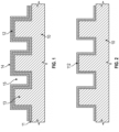
- FIG. 1 is a cross-sectional side view of a coated component 10 (e.g., coated metallic electro-mechanical component 10, such as, for example, a coated stator component 10 or the like), according to certain embodiments of the present disclosure.
- a coated component 10 e.g., coated metallic electro-mechanical component 10, such as, for example, a coated stator component 10 or the like
- the component 10 includes a protective coating 12 positioned on a surface 11 (e.g., outer surface 11) of the component 10. It is noted that surface 11 of component 10 can include or define protrusions 13 and/or recesses 15, with protective coating 12 positioned on the protrusions 13 and/or recesses 15 defined by surface 11.
- an external added layer 14 can be positioned on the protective coating 12 of component 10.
- the external added layer 14 includes a fluorescent agent, as discussed further below.
- FIG. 2 is a cross-sectional side view of another example coated component 10 (e.g., coated metallic electro-mechanical component 10, such as, for example, a coated stator component 10 or the like), according to other embodiments of the present disclosure.
- coated component 10 e.g., coated metallic electro-mechanical component 10, such as, for example, a coated stator component 10 or the like
- component 10 includes a protective coating 112 positioned on a surface 11 of the component 10.
- the protective coating varies from the coating in FIG. 1 at least in that it also includes a fluorescent agent disposed therein.
- FIG. 3 is a cross-sectional side view of another example coated component 10, according to other embodiments of the present disclosure.
- component 10 includes a protective coating 112 positioned on a surface 11 of the component 10.
- an external added layer 14 can be positioned on the protective coating 112 of component 10.
- the external added layer 14 includes a first fluorescent agent
- the protective coating 112 includes a second fluorescent agent.
- the second fluorescent agent of coating 112 is different than the first fluorescent agent of layer 14.
- the different second fluorescent agent of coating 112 versus the first fluorescent agent of layer 14 provides differences in reflection depending on the type of imperfections of component 10.
- the first and second fluorescent agents can be the same as one another.
- the fluorescent agent of external added layer 14 can be mixed in a polymer matrix of the external added layer 14. As noted and as shown in FIG. 1 , this external added layer 14 with the fluorescent agent can be added on top of the existing protective layer 12. In another embodiment and as shown in FIG. 3 , this external added layer 14 with the fluorescent agent can be added on top of the existing protective layer 112, with the layer 112 including a fluorescent agent as discussed above. Moreover and with reference to FIG. 2 , the protective layer can include a fluorescent agent, and can have no external layer 14 positioned thereon.
- FIG. 4 is a cross-sectional side view of FIG. 1 , with a light source 18 (e.g., UV light source 18) for detecting surface degradation of the example coated component 10. It is noted that the component 10 of FIGS. 2 and 3 can also be utilized as shown in FIG. 4 .
- a light source 18 e.g., UV light source 18
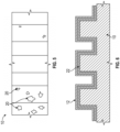
- FIG. 5 is a top view of an example component 10, after a light source detects damage to the example coated component 10 (e.g., a surface view of recorded damage patterns to component 10).
- a light source detects damage to the example coated component 10 (e.g., a surface view of recorded damage patterns to component 10).
- the areas of imperfect or degraded (damaged) coating 20 of component 10 will show a clear indication of no reflection 20, in contrast with neighboring undamaged regions of component 10 with bright reflection from the fluorescent agents (from layers 112 and/or 14). These areas of no reflection 20 indicate the location and size of such damages 20 for a more systematic assessment and decision-making process for service inspection for metallic electro-mechanical components 10.
- light e.g., UV light
- FIG. 6 is a cross-sectional side view of another example coated component 10, according to certain embodiments of the present disclosure.
- component 10 includes an internal added layer 22 positioned on the surface 11 of component 10.
- the internal added layer 22 includes a fluorescent agent.
- component 10 includes a protective coating 12 positioned on internal added layer 22 of the component 10.
- coating 112 (with a fluorescent agent) can be positioned on layer 22 instead of coating 12.
- the fluorescent agent of internal added layer 22 can be mixed in a polymer matrix of the internal added layer 22.
- the internal added layer 22 is positioned on the metallic surface 11 of component 10 below the coating 12.
- the component 10 in a first step, can be covered first with layer 22, the added layer 22 including a fluorescent agent.
- a next step by applying light (e.g., UV light via source 18) to the component 10 with layer 22, a user can check if the reflection of layer 22 is uniform.
- Layer 22 can be re-applied until it is uniformly applied, via checking with applying light via source 18.
- coating 12 can be applied to layer 22.
- this step by applying light (e.g., UV light via source 18) to the component 10 with layer 22 and coating 12, a user can check if the there is still reflections of layer 22, with reflection areas of layer 22 indicating missed areas of coating 12.
- Coating 12 can be re-applied until it is uniformly applied (e.g., via an automated device), via checking with applying light via source 18.
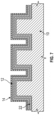
- FIG. 7 is a cross-sectional side view of another example coated component 10, according to certain embodiments of the present disclosure.
- component 10 includes an internal added layer 22 positioned on the surface 11 of component 10.
- the internal added layer 22 includes a fluorescent agent.
- component 10 includes a protective coating 12 positioned on internal added layer 22 of the component 10.
- coating 112 (with a fluorescent agent) can be positioned on layer 22 instead of coating 12.
- the fluorescent agent of internal added layer 22 can be mixed in a polymer matrix of the internal added layer 22.
- the internal added layer 22 is positioned on the metallic surface 11 of component 10 below the coating 12.
- an external added layer 14 can be positioned on the protective coating 12 of component 10.
- the external added layer 14 includes a fluorescent agent (e.g., different than the fluorescent agent of layer 22, although the present disclosure is not limited thereto).
- the present disclosure provides the coatings/layers can be applied as a two-step process, e.g., checking quality before applying layer 14 and then after applying layer 14, the process can be used for assessment of degradations during service, as described below.
- component 10 of FIG. 7 can be changed due to service damage (e.g., corrosion, scratches, etc. of layers 12, 112, 14, 22 and/or component 10 during previous use of component 10).
- service damage e.g., corrosion, scratches, etc. of layers 12, 112, 14, 22 and/or component 10 during previous use of component 10.
- light e.g., UV light via source 18
- the areas of damage of component 10 will show a clear indication of no reflection, in contrast with neighboring undamaged regions of component 10 with bright reflection from the fluorescent agents (from layers 112, 14 and/or 22).
- These areas of no reflection indicate the location and size of such damages 20 for a more systematic assessment and decision-making process for service inspection for metallic electro-mechanical components 10 (e.g., regarding repair, replacement of component 10).
- Some example fluorescent agents for layers 14, 22 and/or coating 112 include, without limitation, dyes and/or pigments.
- fluorescent agents and/or dyes that absorb UV light e.g., around 350 nm
- fluoresce in the visible spectrum can be utilized (e.g., added in the polymer composite resins and/or fibers of layers 14, 22 and/or coating 112).
- fluorescent agents include, without limitation: anthrathioxanthene, thioxanthene benzanthrone or anthraquinone series based chemistries.
- One example has the following molecular formula:
- xanthene benzothioxanthene-dicarboximide, and aminoketones series-based chemistries can be utilized. Examples have the following molecular formulae:
- Solvent yellow 98 Fluorescent YELLOW 3GF
- Hostasol Yellow 3G Solvent Fluorescent Yellow 3G
- Rosaplast Yellow F5G Keyplast Fluorecent Yellow 3R
- RADGLo CFS-6-03 RED Solvent Red 49.
- Another example includes benzopyran based chemistry.
- One example has the following molecular formula:
- This colorant is known under the trade name RADGLO CFS-6-02 RED, and Solvent Red 196.
- Another example is azomethine based chemistry.
- One example has the following molecular formula:
- This colorant is known under the trade name RADGLO VSF-0-01 Yellow. Upon UV excitation, it fluoresces in yellow/green color.
- UV fluorescent thermoset resin pigments under several commercial names can be utilized, such as, for example: (i) RADGLO ® P-09 UV Blue pigment (solid solution of dyestuffs in a thermoset sulphonamide-melamine-paraformaldehyde polymer resin); (ii) RADGLO GM family of dyed/pigmented (range of colors) thermoset modified benzoguanamine-formaldehyde copolymer; (iii) RADGLO GRT family of dyed/pigmented (range of colors) thermoset polyester amide copolymers; and/or (iv) RADGLO PC and RADGLO PS families of dyed/pigmented (range of colors) thermoset sulphonamide-melamine-paraformaldehyde polymer resin.
- RADGLO ® P-09 UV Blue pigment solid solution of dyestuffs in a thermoset sulphonamide-melamine-paraformaldehyde polymer resin
- ranges disclosed herein are inclusive of the endpoints, and the endpoints are independently combinable with each other (e.g., ranges of "up to 25 wt.%, or, more specifically, 5 wt.% to 20 wt.%", is inclusive of the endpoints and all intermediate values of the ranges of "5 wt.% to 25 wt.%,” etc.).
- “Combinations” is inclusive of blends, mixtures, alloys, reaction products, and the like.
- the terms “first,” “second,” and the like, do not denote any order, quantity, or importance, but rather are used to distinguish one element from another.
Landscapes
- Physics & Mathematics (AREA)
- Health & Medical Sciences (AREA)
- Life Sciences & Earth Sciences (AREA)
- Chemical & Material Sciences (AREA)
- Pathology (AREA)
- Biochemistry (AREA)
- General Health & Medical Sciences (AREA)
- General Physics & Mathematics (AREA)
- Immunology (AREA)
- Analytical Chemistry (AREA)
- Engineering & Computer Science (AREA)
- Nuclear Medicine, Radiotherapy & Molecular Imaging (AREA)
- Spectroscopy & Molecular Physics (AREA)
- Signal Processing (AREA)
- Computer Vision & Pattern Recognition (AREA)
- Mathematical Physics (AREA)
- Environmental Sciences (AREA)
- Environmental & Geological Engineering (AREA)
- Ecology (AREA)
- Biodiversity & Conservation Biology (AREA)
- Food Science & Technology (AREA)
- Medicinal Chemistry (AREA)
- Investigating Materials By The Use Of Optical Means Adapted For Particular Applications (AREA)
Abstract
Description
- The present disclosure relates to assemblies, systems and methods of quality control and service inspection for metallic electro-mechanical components and, more particularly, to assemblies, systems and methods of quality control and service inspection for metallic electro-mechanical components (e.g., stator components) utilizing fluorescent agents.
- In general, to protect electro-mechanical components from corrosion, a protective coating can be used as an applied sprayed barrier layer (e.g., paint). However, there is a risk of inadequate coating coverage (e.g., with spottiness of the applied layer). Therefore, quality control of coating coverage can be a challenge for various reasons (e.g., due to complex surface shapes, hard-to-see internal corners, small sizes of imperfectly coated areas (spottiness), etc.).
- Another challenge is expected corrosion during operation due to harsh environments or the like. Thus, detection of operational corrosion can be needed for pro-active maintenance (e.g., replacement, repair, etc.) and/or optimization of a protective coating. However, accurate detection of operational corrosion can be a difficult task (e.g., due to poor contrast, limited visibility and access, and potential subjectivity of assessment, especially, at the beginning of a corrosion process).
- The present disclosure provides assemblies for quality control and service inspection for metallic electro-mechanical components, and improved systems/methods of quality control and service inspection for metallic electro-mechanical components. More particularly, the present disclosure provides embodiments that may result in improved assemblies, systems and methods of quality control and service inspection for metallic electro-mechanical components (e.g., aircraft stator components) utilizing fluorescent agents.
- The present disclosure provides for a coated assembly including a metallic electro-mechanical component having an outer surface; and a protective coating or a first added layer positioned proximal to the outer surface, the protective coating or the first added layer comprising a first fluorescent agent; and wherein the first fluorescent agent operates as bright contrast media under a light source to identify imperfect coating or coating degradation during service of the metallic electro-mechanical component.
- In embodiments, the protective coating is positioned on the outer surface, and the first added layer is positioned on the protective coating.
- In embodiments, the first added layer comprises the first fluorescent agent, and the protective coating is free of the first fluorescent agent.
- In embodiments, the protective coating is positioned on the outer surface, and the metallic electro-mechanical component is free of the first added layer, the protective coating comprising the first fluorescent agent.
- In embodiments, the protective coating comprises the first fluorescent agent, and the first added layer comprises a second fluorescent agent.
- In embodiments, the first added layer is positioned on the outer surface, and the protective coating is positioned on the first added layer, the first added layer comprising the first fluorescent agent.
- In embodiments, the protective coating comprises a second fluorescent agent.
- In embodiments, a second added layer is positioned on the protective coating, the second added layer comprising a second fluorescent agent.
- In embodiments, the protective coating comprises a third fluorescent agent.
- In embodiments, the metallic electro-mechanical component is a stator metallic component, and the first fluorescent agent is a dye or a pigment; and the outer surface defines a plurality of protrusions and recesses.
- The present disclosure provides for an inspection method including providing a metallic electro-mechanical component having an outer surface; and positioning a protective coating or a first added layer proximal to the outer surface, the protective coating or the first added layer comprising a first fluorescent agent; and applying a light source onto the metallic electro-mechanical component, with the first fluorescent agent operating as bright contrast media under the light source to identify imperfect coating or coating degradation during service of the metallic electro-mechanical component.
- In embodiments, the protective coating is positioned on the outer surface, and the first added layer is positioned on the protective coating; and the first added layer comprises the first fluorescent agent, and the protective coating is free of the first fluorescent agent; and wherein by applying light via the light source to the component, areas of imperfect or degraded coating of the component show an indication of no reflection of light, in contrast with neighboring undamaged regions of the component having bright reflection from the first fluorescent agent, and the areas of no reflection indicate the location and size of imperfect or degraded coating to the component during service inspection.
- In embodiments, the protective coating is positioned on the outer surface, and the metallic electro-mechanical component is free of the first added layer, the protective coating comprising the first fluorescent agent; and wherein by applying light via the light source to the component, areas of imperfect or degraded coating of the component show an indication of no reflection of light, in contrast with neighboring undamaged regions of the component having bright reflection from the first fluorescent agent, and the areas of no reflection indicate the location and size of imperfect or degraded coating to the component during service inspection.
- In embodiments, the protective coating is positioned on the outer surface, and the first added layer is positioned on the protective coating; and the protective coating comprises the first fluorescent agent, and the first added layer comprises a second fluorescent agent; and wherein by applying light via the light source to the component, areas of imperfect or degraded coating of the component show an indication of no reflection of light, in contrast with neighboring undamaged regions of the component having bright reflection from the first or second fluorescent agents, and the areas of no reflection indicate the location and size of imperfect or degraded coating to the component during service inspection.
- In embodiments, the first added layer is positioned on the outer surface, and the protective coating is positioned on the first added layer, the first added layer comprising the first fluorescent agent; and wherein by applying light via the light source to the component, areas of spottiness of the protective coating show an indication of reflection from the first fluorescent agent of the first added layer, in contrast with neighboring protective coated regions of the component with no reflection from the first fluorescent agent, and the areas of reflection indicate the location and size of imperfections of the protective coating of the component during a quality control assessment.
- In embodiments, the first added layer is positioned on the outer surface, and the protective coating is positioned on the first added layer, the first added layer comprising the first fluorescent agent; and further comprising a second added layer positioned on the protective coating, the second added layer comprising a second fluorescent agent; and wherein by applying light via the light source to the component, areas of imperfect or degraded coating of the component show an indication of no reflection of light, in contrast with neighboring undamaged regions of the component having bright reflection from the first or second fluorescent agents, and the areas of no reflection indicate the location and size of imperfect or degraded coating to the component during service inspection.
- In embodiments, wherein the metallic electro-mechanical component is a stator metallic component, and the first fluorescent agent is a dye or a pigment; and the outer surface defines a plurality of protrusions and recesses.
- The present disclosure provides for an inspection method including providing a metallic electro-mechanical component having an outer surface; and positioning an added layer on the outer surface, the added layer comprising a fluorescent agent; and applying a light source onto the added layer to determine if the added layer was applied uniformly; and re-apply the added layer on the outer surface if the added layer was determined to be not applied uniformly; and positioning a protective coating on the uniformly applied added layer; and applying a light source onto the metallic electro-mechanical component, with the fluorescent agent operating as bright contrast media under the light source to identify imperfect coating of the metallic electro-mechanical component.
- In embodiments, wherein by applying light via the light source to the component, areas of spottiness of the protective coating show an indication of reflection from the fluorescent agent of the added layer, in contrast with neighboring protective coated regions of the component with no reflection from the fluorescent agent, and the areas of reflection indicate the location and size of imperfections of the protective coating of the component during a quality control assessment.
- In embodiments, the metallic electro-mechanical component is a stator metallic component, and the fluorescent agent is a dye or a pigment; and the outer surface defines a plurality of protrusions and recesses.
- The above described and other features are exemplified by the following figures and detailed description.
- Any combination or permutation of embodiments is envisioned provided it falls within the scope of the claims. Additional features, functions and applications of the disclosed assemblies, systems and methods of the present disclosure will be apparent from the description which follows, particularly when read in conjunction with the appended figures.
- The following figures are example embodiments wherein the like elements are numbered alike.
- Features and aspects of embodiments are described below with reference to the accompanying drawings, in which elements are not necessarily depicted to scale.
- Example embodiments of the present disclosure are further described with reference to the appended figures. It is to be noted that the various features, steps, and combinations of features/steps described below and illustrated in the figures can be arranged and organized differently to result in embodiments which are still within the scope of the present invention as defined by the claims. To assist those of ordinary skill in the art in making and using the disclosed assemblies, systems and methods, reference is made to the appended figures, wherein:
-
FIG. 1 is a cross-sectional side view of an example coated component, according to the present disclosure; -
FIG. 2 is a cross-sectional side view of another example coated component, according to the present disclosure; -
FIG. 3 is a cross-sectional side view of another example coated component, according to the present disclosure; -
FIG. 4 is a cross-sectional side view ofFIG. 1 , with a light source for detecting damage to the example coated component; -
FIG. 5 is a top view of an example component, after a light source detects damage to the example coated component; -
FIG. 6 is a cross-sectional side view of another example coated component, according to the present disclosure; and -
FIG. 7 is a cross-sectional side view of another example coated component, according to the present disclosure. - The example embodiments disclosed herein are illustrative of assemblies for quality control and service inspection for metallic electro-mechanical components, and systems of the present disclosure and methods/techniques thereof. It should be understood, however, that the disclosed embodiments are merely examples of the present disclosure, which may be embodied in various forms. Therefore, details disclosed herein with reference to example assemblies for quality control and service inspection for metallic electro-mechanical components and associated processes/techniques of fabrication/assembly and use are not to be interpreted as limiting, but merely as the basis for teaching one skilled in the art how to make and use the assemblies/systems and/or alternative assemblies/systems of the present disclosure.
- The present disclosure provides assemblies, systems and methods of quality control and service inspection for metallic electro-mechanical components.
- More particularly, the present disclosure provides assemblies, systems and methods of quality control and service inspection for metallic electro-mechanical components (e.g., aircraft metallic stator components) utilizing fluorescent agents.
- Current practice provides that a protective coating (e.g., applied sprayed barrier layer) can be used to attempt to protect electro-mechanical components from corrosion; however, quality control of coating coverage can be a challenge for various reasons as discussed above. Moreover, detection of operational corrosion can be needed for pro-active maintenance and/or optimization of a protective coating but accurate detection of such corrosion can be a difficult task.
- The present disclosure provides both (i) surface/assembly designs, and (ii) methods of their inspection. In example embodiments of the present disclosure, fluorescent agents can be mixed with protective and/or added layers to serve as bright contrast media under a light source (e.g., ultraviolet ("UV") light source). It is noted that in a case of imperfect coating or coating degraded during service (e.g., due to corrosion), gaps in fluorescent reflection can serve as clear indications of either inadequate quality or excessive corrosion-driven degradation of the components.
-
FIG. 1 is a cross-sectional side view of a coated component 10 (e.g., coated metallic electro-mechanical component 10, such as, for example, a coatedstator component 10 or the like), according to certain embodiments of the present disclosure. - The
component 10 includes aprotective coating 12 positioned on a surface 11 (e.g., outer surface 11) of thecomponent 10. It is noted that surface 11 ofcomponent 10 can include or defineprotrusions 13 and/orrecesses 15, withprotective coating 12 positioned on theprotrusions 13 and/orrecesses 15 defined by surface 11. - As depicted in
FIG. 1 , an external addedlayer 14 can be positioned on theprotective coating 12 ofcomponent 10. In certain embodiments, the external addedlayer 14 includes a fluorescent agent, as discussed further below. -
FIG. 2 is a cross-sectional side view of another example coated component 10 (e.g., coated metallic electro-mechanical component 10, such as, for example, a coatedstator component 10 or the like), according to other embodiments of the present disclosure. - As shown in
FIG. 2 ,component 10 includes aprotective coating 112 positioned on a surface 11 of thecomponent 10. InFIG. 2 , the protective coating varies from the coating inFIG. 1 at least in that it also includes a fluorescent agent disposed therein. -
FIG. 3 is a cross-sectional side view of another example coatedcomponent 10, according to other embodiments of the present disclosure. As shown inFIG. 3 ,component 10 includes aprotective coating 112 positioned on a surface 11 of thecomponent 10. As depicted inFIG. 3 , an external addedlayer 14 can be positioned on theprotective coating 112 ofcomponent 10. In certain embodiments, the external addedlayer 14 includes a first fluorescent agent, and theprotective coating 112 includes a second fluorescent agent. In general and without limitation regardingFIG. 3 , the second fluorescent agent ofcoating 112 is different than the first fluorescent agent oflayer 14. In such embodiments, the different second fluorescent agent ofcoating 112 versus the first fluorescent agent oflayer 14 provides differences in reflection depending on the type of imperfections ofcomponent 10. In other embodiments, it is noted that the first and second fluorescent agents can be the same as one another. - With reference again to
FIG. 1 , the fluorescent agent of external addedlayer 14 can be mixed in a polymer matrix of the external addedlayer 14. As noted and as shown inFIG. 1 , this external addedlayer 14 with the fluorescent agent can be added on top of the existingprotective layer 12. In another embodiment and as shown inFIG. 3 , this external addedlayer 14 with the fluorescent agent can be added on top of the existingprotective layer 112, with thelayer 112 including a fluorescent agent as discussed above. Moreover and with reference toFIG. 2 , the protective layer can include a fluorescent agent, and can have noexternal layer 14 positioned thereon. - In regards to a system and method for service inspection for metallic electro-mechanical components 10 (e.g., a
metallic stator component 10 or the like) and with continued reference toFIGS. 1-3 , it is noted that the ability ofcomponent 10 ofFIGS. 1-3 to reflect light in relatively dark confined spaces can be changed due to operational damage (e.g., corrosion, scratches, etc. oflayers component 10 during previous use of component 10). By applying light (e.g., UV light) to thecomponent 10 ofFIGS. 1-3 , the areas of damage ofcomponent 10 will show a clear indication of no reflection, in contrast with neighboring undamaged regions ofcomponent 10 with bright reflection from the fluorescent agents (fromlayers 112 and/or 14). These areas of no reflection indicate the location and size of such areas of degraded coating for a more systematic assessment and decision-making process for service inspection for metallic electro-mechanical components 10 (e.g., regarding repair, replacement ofcomponent 10 or taking no actions at current level of coating degradation). -
FIG. 4 is a cross-sectional side view ofFIG. 1 , with a light source 18 (e.g., UV light source 18) for detecting surface degradation of the example coatedcomponent 10. It is noted that thecomponent 10 ofFIGS. 2 and3 can also be utilized as shown inFIG. 4 . -
FIG. 5 is a top view of anexample component 10, after a light source detects damage to the example coated component 10 (e.g., a surface view of recorded damage patterns to component 10). - As described above and with reference now to
FIGS. 4 and5 , by applying light (e.g., UV light) vialight source 18 to thecomponent 10 ofFIGS. 1-3 , the areas of imperfect or degraded (damaged) coating 20 ofcomponent 10 will show a clear indication of noreflection 20, in contrast with neighboring undamaged regions ofcomponent 10 with bright reflection from the fluorescent agents (fromlayers 112 and/or 14). These areas of noreflection 20 indicate the location and size ofsuch damages 20 for a more systematic assessment and decision-making process for service inspection for metallic electro-mechanical components 10. -
FIG. 6 is a cross-sectional side view of another example coatedcomponent 10, according to certain embodiments of the present disclosure. As depicted inFIG. 6 ,component 10 includes an internal addedlayer 22 positioned on the surface 11 ofcomponent 10. In certain embodiments, the internal addedlayer 22 includes a fluorescent agent. As shown inFIG. 6 ,component 10 includes aprotective coating 12 positioned on internal addedlayer 22 of thecomponent 10. In another embodiment, it is noted that coating 112 (with a fluorescent agent) can be positioned onlayer 22 instead of coating 12. - With continued reference to
FIG. 6 , the fluorescent agent of internal addedlayer 22 can be mixed in a polymer matrix of the internal addedlayer 22. In example embodiments, the internal addedlayer 22 is positioned on the metallic surface 11 ofcomponent 10 below thecoating 12. - In regards to a system and method for quality control for metallic electro-mechanical components 10 (e.g., quality control for new, repaired and/or un-serviced components 10) and with continued reference to
FIG. 6 , it is noted that the ability ofcomponent 10 ofFIG. 6 to reflect light in relatively dark confined spaces can be changed due to inadequate coating coverage of coating 12 of component 10 (e.g., spottiness of coating 12). By applying light (e.g., UV light via source 18) to thecomponent 10 ofFIG. 6 , the areas of spottiness of coating 12 ofcomponent 10 will show a clear indication of reflection fromlayer 22, in contrast with neighboringcoated regions 12 ofcomponent 10 with no reflection from the fluorescent agent fromlayer 22. These areas of reflection indicate the location and size of such local imperfections of thecoating 12 for a more systematic quality assessment and decision-making process for quality control of metallic electro-mechanical components 10 (e.g., regarding quality-based acceptance/rejection or improvement solutions for component 10). - In example embodiments for a system and method for quality control for
components 10, it is noted that in a first step, thecomponent 10 can be covered first withlayer 22, the addedlayer 22 including a fluorescent agent. In a next step, by applying light (e.g., UV light via source 18) to thecomponent 10 withlayer 22, a user can check if the reflection oflayer 22 is uniform.Layer 22 can be re-applied until it is uniformly applied, via checking with applying light viasource 18. Afterlayer 22 is uniformly applied, then coating 12 can be applied tolayer 22. After this step, by applying light (e.g., UV light via source 18) to thecomponent 10 withlayer 22 andcoating 12, a user can check if the there is still reflections oflayer 22, with reflection areas oflayer 22 indicating missed areas ofcoating 12.Coating 12 can be re-applied until it is uniformly applied (e.g., via an automated device), via checking with applying light viasource 18. -
FIG. 7 is a cross-sectional side view of another example coatedcomponent 10, according to certain embodiments of the present disclosure. As depicted inFIG. 7 ,component 10 includes an internal addedlayer 22 positioned on the surface 11 ofcomponent 10. In certain embodiments, the internal addedlayer 22 includes a fluorescent agent. As shown inFIG. 7 ,component 10 includes aprotective coating 12 positioned on internal addedlayer 22 of thecomponent 10. In another embodiment, it is noted that coating 112 (with a fluorescent agent) can be positioned onlayer 22 instead of coating 12. - With continued reference to
FIG. 7 , the fluorescent agent of internal addedlayer 22 can be mixed in a polymer matrix of the internal addedlayer 22. In example embodiments, the internal addedlayer 22 is positioned on the metallic surface 11 ofcomponent 10 below thecoating 12. - As depicted in
FIG. 7 , an external addedlayer 14 can be positioned on theprotective coating 12 ofcomponent 10. In certain embodiments, the external addedlayer 14 includes a fluorescent agent (e.g., different than the fluorescent agent oflayer 22, although the present disclosure is not limited thereto). - In a system and method for quality control for components 10 (e.g., quality control for new, repaired and/or un-serviced components 10) and with continued reference to
FIG. 7 , it is noted that the ability ofun-serviced component 10 ofFIG. 7 to reflect light in relatively dark confined spaces can be changed due to inadequate coating coverage of coating 12 of component 10 (e.g., spottiness ofcoating 12, before applying layer 14). By applying light (e.g., UV light via source 18) to thecomponent 10 ofFIG. 7 (before applying layer 14), the areas of spottiness of coating 12 ofcomponent 10 will show a clear indication of reflection fromlayer 22, in contrast with neighboringcoated regions 12 ofcomponent 10 with no reflection from the fluorescent agent frominternal layer 22. These areas of reflection indicate the location and size of such local imperfections of thecoating 12 for a more systematic quality assessment and decision-making process for quality control of metallic electro-mechanical components 10 (e.g., regarding acceptance/rejection or improvement solutions for component 10). As such, the present disclosure provides the coatings/layers can be applied as a two-step process, e.g., checking quality before applyinglayer 14 and then after applyinglayer 14, the process can be used for assessment of degradations during service, as described below. - With continued reference to
FIG. 7 and in regards to a system and method for service inspection forcomponents 10, it is noted that the ability ofcomponent 10 ofFIG. 7 to reflect light in relatively dark confined spaces can be changed due to service damage (e.g., corrosion, scratches, etc. oflayers component 10 during previous use of component 10). By applying light (e.g., UV light via source 18) to thecomponent 10 ofFIG. 7 , the areas of damage ofcomponent 10 will show a clear indication of no reflection, in contrast with neighboring undamaged regions ofcomponent 10 with bright reflection from the fluorescent agents (fromlayers such damages 20 for a more systematic assessment and decision-making process for service inspection for metallic electro-mechanical components 10 (e.g., regarding repair, replacement of component 10). - Some example fluorescent agents for
layers coating 112 include, without limitation, dyes and/or pigments. - For example, fluorescent agents and/or dyes that absorb UV light (e.g., around 350 nm) and fluoresce in the visible spectrum can be utilized (e.g., added in the polymer composite resins and/or fibers of
layers - Some example fluorescent agents include, without limitation: anthrathioxanthene, thioxanthene benzanthrone or anthraquinone series based chemistries. One example has the following molecular formula:

- These family of colorants are known under the trade names Solvent Orange 63, Fluorescent Red GG, Hostasol Red GG, or Macolox Fluorescent Red GG.
- In other example embodiments, xanthene, benzothioxanthene-dicarboximide, and aminoketones series-based chemistries can be utilized. Examples have the following molecular formulae:

- These family of colorant(s) are known under the trade names Solvent yellow 98, Fluorescent YELLOW 3GF, Hostasol Yellow 3G, Solvent Fluorescent Yellow 3G, Rosaplast Yellow F5G, Keyplast Fluorecent Yellow 3R, RADGLo CFS-6-03 RED or Solvent Red 49.
- Other examples include coumarin, coumarin 480, hydroxycoumarin, and glycidyl-oxycoumarin of the molecular formulae below:

- These chemistries upon UV excitation fluoresce in the blue range of the visible spectrum (e.g., 400 to 500 nm).
- Another example includes benzopyran based chemistry. One example has the following molecular formula:

- This colorant is known under the trade name RADGLO CFS-6-02 RED, and Solvent Red 196.
- Another example is azomethine based chemistry. One example has the following molecular formula:

- This colorant is known under the trade name RADGLO VSF-0-01 Yellow. Upon UV excitation, it fluoresces in yellow/green color.
- Other examples include naphthalimide and perylene based chemistries. Examples have the following molecular formulae:

- These colorants are known under the trade name RADGLO CFS-0-01 Yellow or Solvent Yellow 43, RADGLO CFS-0-05 or Solvent Green 5. Upon UV excitation, it fluoresces in yellow/green color.
- Some various UV fluorescent thermoset resin pigments under several commercial names can be utilized, such as, for example: (i) RADGLO® P-09 UV Blue pigment (solid solution of dyestuffs in a thermoset sulphonamide-melamine-paraformaldehyde polymer resin); (ii) RADGLO GM family of dyed/pigmented (range of colors) thermoset modified benzoguanamine-formaldehyde copolymer; (iii) RADGLO GRT family of dyed/pigmented (range of colors) thermoset polyester amide copolymers; and/or (iv) RADGLO PC and RADGLO PS families of dyed/pigmented (range of colors) thermoset sulphonamide-melamine-paraformaldehyde polymer resin.
- There are many benefits of the assemblies, systems and methods of the present disclosure, including, without limitation: high reliability of detection of inadequate quality or excessive corrosion degradation; efficiency (convenience and robustness) of implementation; low cost and low demand of specially trained labor; opportunity to apply it as express method for coating optimization and/or benchmarking; opportunity to use available fluorescent agents; and/or the opportunity to utilize with both aircraft and non-aircraft components.
- While particular embodiments have been described, alternatives, modifications, variations, improvements, and substantial equivalents that are or may be presently unforeseen may arise to applicants or others skilled in the art. Accordingly, the appended claims as filed and as they may be amended are intended to embrace all such alternatives, modifications variations, improvements, and substantial equivalents.
- The ranges disclosed herein are inclusive of the endpoints, and the endpoints are independently combinable with each other (e.g., ranges of "up to 25 wt.%, or, more specifically, 5 wt.% to 20 wt.%", is inclusive of the endpoints and all intermediate values of the ranges of "5 wt.% to 25 wt.%," etc.). "Combinations" is inclusive of blends, mixtures, alloys, reaction products, and the like. The terms "first," "second," and the like, do not denote any order, quantity, or importance, but rather are used to distinguish one element from another. The terms "a" and "an" and "the" do not denote a limitation of quantity and are to be construed to cover both the singular and the plural, unless otherwise indicated herein or clearly contradicted by context. "Or" means "and/or" unless clearly stated otherwise. Reference throughout the specification to "some embodiments", "an embodiment", and so forth, means that a particular element described in connection with the embodiment is included in at least one embodiment described herein, and may or may not be present in other embodiments. In addition, it is to be understood that the described elements may be combined in any suitable manner in the various embodiments. A "combination thereof' is open and includes any combination comprising at least one of the listed components or properties optionally together with a like or equivalent component or property not listed.
- Unless defined otherwise, technical and scientific terms used herein have the same meaning as is commonly understood by one of skill in the art to which this application belongs.
- Although the systems and methods of the present disclosure have been described with reference to example embodiments thereof, the present disclosure is not limited to such example embodiments and/or implementations. Rather, the systems and methods of the present disclosure are susceptible to many implementations and applications, as will be readily apparent to persons skilled in the art from the disclosure hereof, and as fall within the scope of the claims. The present disclosure expressly encompasses such modifications, enhancements and/or variations of the disclosed embodiments. Since many changes could be made in the above construction and many widely different embodiments of this disclosure could be made without departing from the scope of the claims, it is intended that all matter contained in the drawings and specification shall be interpreted as illustrative and not in a limiting sense. Additional modifications, changes, and substitutions are intended in the foregoing disclosure.
Claims (15)
- A coated assembly comprising:a metallic electro-mechanical component (10) having an outer surface (11); anda protective coating (12) or a first added layer (14) positioned proximal to the outer surface, the protective coating or the first added layer comprising a first fluorescent agent;wherein the first fluorescent agent operates as bright contrast media under a light source to identify imperfect coating or coating degradation during service of the metallic electro-mechanical component.
- The assembly of claim 1, wherein the protective coating is positioned on the outer surface, and the first added layer is positioned on the protective coating
- The assembly of claim 2, wherein the first added layer comprises the first fluorescent agent, and the protective coating is free of the first fluorescent agent.
- The assembly of claim 1, wherein the protective coating is positioned on the outer surface, and the metallic electro-mechanical component is free of the first added layer, the protective coating comprising the first fluorescent agent.
- The assembly of claim 2, wherein the protective coating comprises the first fluorescent agent, and the first added layer comprises a second fluorescent agent.
- The assembly of claim 1, wherein the first added layer is positioned on the outer surface, and the protective coating is positioned on the first added layer, the first added layer comprising the first fluorescent agent.
- The assembly of claim 6, wherein the protective coating comprises a second fluorescent agent.
- The assembly of claim 6 further comprising a second added layer positioned on the protective coating, the second added layer comprising a second fluorescent agent, and optionally wherein the protective coating comprises a third fluorescent agent.
- The assembly of any preceding claim, wherein the metallic electro-mechanical component is a stator metallic component, and the first fluorescent agent is a dye or a pigment; and
wherein the outer surface defines a plurality of protrusions and recesses. - An inspection method comprising:providing a metallic electro-mechanical component (10) having an outer surface (11); andpositioning a protective coating (12) or a first added layer (14) proximal to the outer surface, the protective coating or the first added layer comprising a first fluorescent agent;applying a light source (18) onto the metallic electro-mechanical component, with the first fluorescent agent operating as bright contrast media under the light source to identify imperfect coating or coating degradation during service of the metallic electro-mechanical component.
- The method of claim 10, wherein the protective coating is positioned on the outer surface, and the first added layer is positioned on the protective coating; andwherein the first added layer comprises the first fluorescent agent, and the protective coating is free of the first fluorescent agent; andwherein by applying light via the light source to the component, areas of imperfect or degraded coating of the component show an indication of no reflection of light, in contrast with neighboring undamaged regions of the component having bright reflection from the first fluorescent agent, and the areas of no reflection indicate the location and size of imperfect or degraded coating to the component during service inspection; orwherein the protective coating is positioned on the outer surface, and the metallic electro-mechanical component is free of the first added layer, the protective coating comprising the first fluorescent agent; andwherein by applying light via the light source to the component, areas of imperfect or degraded coating of the component show an indication of no reflection of light, in contrast with neighboring undamaged regions of the component having bright reflection from the first fluorescent agent, and the areas of no reflection indicate the location and size of imperfect or degraded coating to the component during service inspection; orwherein the protective coating is positioned on the outer surface, and the first added layer is positioned on the protective coating; andwherein the protective coating comprises the first fluorescent agent, and the first added layer comprises a second fluorescent agent;wherein by applying light via the light source to the component, areas of imperfect or degraded coating of the component show an indication of no reflection of light, in contrast with neighboring undamaged regions of the component having bright reflection from the first or second fluorescent agents, and the areas of no reflection indicate the location and size of imperfect or degraded coating to the component during service inspection; orwherein the first added layer is positioned on the outer surface, and the protective coating is positioned on the first added layer, the first added layer comprising the first fluorescent agent; andwherein by applying light via the light source to the component, areas of spottiness of the protective coating show an indication of reflection from the first fluorescent agent of the first added layer, in contrast with neighboring protective coated regions of the component with no reflection from the first fluorescent agent, and the areas of reflection indicate the location and size of imperfections of the protective coating of the component during a quality control assessment; orwherein the first added layer is positioned on the outer surface, and the protective coating is positioned on the first added layer, the first added layer comprising the first fluorescent agent;further comprising a second added layer positioned on the protective coating, the second added layer comprising a second fluorescent agent;wherein by applying light via the light source to the component, areas of imperfect or degraded coating of the component show an indication of no reflection of light, in contrast with neighboring undamaged regions of the component having bright reflection from the first or second fluorescent agents, and the areas of no reflection indicate the location and size of imperfect or degraded coating to the component during service inspection.
- The method of claim 10, wherein the metallic electro-mechanical component is a stator metallic component, and the first fluorescent agent is a dye or a pigment; and
wherein the outer surface defines a plurality of protrusions and recesses. - An inspection method comprising:providing a metallic electro-mechanical component (10) having an outer surface (11); andpositioning an added layer (14) on the outer surface, the added layer comprising a fluorescent agent;applying a light source (18) onto the added layer to determine if the added layer was applied uniformly;re-apply the added layer on the outer surface if the added layer was determined to be not applied uniformly;positioning a protective coating on the uniformly applied added layer;applying a light source onto the metallic electro-mechanical component, with the fluorescent agent operating as bright contrast media under the light source to identify imperfect coating of the metallic electro-mechanical component.
- The method of claim 13, wherein by applying light via the light source to the component, areas of spottiness of the protective coating show an indication of reflection from the fluorescent agent of the added layer, in contrast with neighboring protective coated regions of the component with no reflection from the fluorescent agent, and the areas of reflection indicate the location and size of imperfections of the protective coating of the component during a quality control assessment.
- The method of claim 13 or 14, wherein the metallic electro-mechanical component is a stator metallic component, and the fluorescent agent is a dye or a pigment; and
wherein the outer surface defines a plurality of protrusions and recesses.
Applications Claiming Priority (1)
| Application Number | Priority Date | Filing Date | Title |
|---|---|---|---|
| US17/713,903 US20230314304A1 (en) | 2022-04-05 | 2022-04-05 | Method of quality control and service inspection for metallic electro-mechanical components |
Publications (1)
| Publication Number | Publication Date |
|---|---|
| EP4257959A1 true EP4257959A1 (en) | 2023-10-11 |
Family
ID=85726976
Family Applications (1)
| Application Number | Title | Priority Date | Filing Date |
|---|---|---|---|
| EP23163534.3A Pending EP4257959A1 (en) | 2022-04-05 | 2023-03-22 | Method of quality control and service inspection for metallic electro-mechanical components |
Country Status (2)
| Country | Link |
|---|---|
| US (1) | US20230314304A1 (en) |
| EP (1) | EP4257959A1 (en) |
Citations (7)
| Publication number | Priority date | Publication date | Assignee | Title |
|---|---|---|---|---|
| US5241184A (en) * | 1991-09-26 | 1993-08-31 | Electric Power Research Institute | Apparatus and method for quantizing remaining lifetime of transmission cable insulation |
| WO1995032060A1 (en) * | 1994-05-20 | 1995-11-30 | Deardorff James R | Ultraviolet reactive coating system |
| FR2836229A1 (en) * | 2002-02-15 | 2003-08-22 | Lilian Martinez | Control of the integrity and/or degradation of a coating involves using a coating that has detectable luminescence under electromagnetic excitation |
| US20040113070A1 (en) * | 2002-12-13 | 2004-06-17 | Bruce Nichols | Method and apparatus for determining electrical contact wear |
| JP2008061345A (en) * | 2006-08-30 | 2008-03-13 | Sumitomo Wiring Syst Ltd | Concentrated power distribution member for motor |
| US8304242B2 (en) * | 2007-12-17 | 2012-11-06 | Life Technologies Corporation | Methods for detecting defects in inorganic-coated polymer surfaces |
| WO2021090208A1 (en) * | 2019-11-08 | 2021-05-14 | 3M Innovative Properties Company | Ultraviolet light-based inspection for detecting coating defects in manufactured webs using fluorescing agents |
Family Cites Families (4)
| Publication number | Priority date | Publication date | Assignee | Title |
|---|---|---|---|---|
| US5472878A (en) * | 1992-11-16 | 1995-12-05 | Microbiomed Corp. | Fluorescent method for monitoring oil degradation |
| WO2013052484A1 (en) * | 2011-10-03 | 2013-04-11 | Immunomedics, Inc. | Dye conjugated peptides for fluorescent imaging |
| US8530861B1 (en) * | 2012-05-01 | 2013-09-10 | Empire Technology Development Llc | Detectably-labeled carbon fiber |
| CN106637187A (en) * | 2016-11-16 | 2017-05-10 | 中国人民解放军第五七九工厂 | Laser cladding restoration method for damage of stator blade of welding assembly of large fan casing of aeroengine |
-
2022
- 2022-04-05 US US17/713,903 patent/US20230314304A1/en not_active Abandoned
-
2023
- 2023-03-22 EP EP23163534.3A patent/EP4257959A1/en active Pending
Patent Citations (7)
| Publication number | Priority date | Publication date | Assignee | Title |
|---|---|---|---|---|
| US5241184A (en) * | 1991-09-26 | 1993-08-31 | Electric Power Research Institute | Apparatus and method for quantizing remaining lifetime of transmission cable insulation |
| WO1995032060A1 (en) * | 1994-05-20 | 1995-11-30 | Deardorff James R | Ultraviolet reactive coating system |
| FR2836229A1 (en) * | 2002-02-15 | 2003-08-22 | Lilian Martinez | Control of the integrity and/or degradation of a coating involves using a coating that has detectable luminescence under electromagnetic excitation |
| US20040113070A1 (en) * | 2002-12-13 | 2004-06-17 | Bruce Nichols | Method and apparatus for determining electrical contact wear |
| JP2008061345A (en) * | 2006-08-30 | 2008-03-13 | Sumitomo Wiring Syst Ltd | Concentrated power distribution member for motor |
| US8304242B2 (en) * | 2007-12-17 | 2012-11-06 | Life Technologies Corporation | Methods for detecting defects in inorganic-coated polymer surfaces |
| WO2021090208A1 (en) * | 2019-11-08 | 2021-05-14 | 3M Innovative Properties Company | Ultraviolet light-based inspection for detecting coating defects in manufactured webs using fluorescing agents |
Non-Patent Citations (1)
| Title |
|---|
| LAURENT C ET AL: "Semi-quantitative analysis of photoluminescence in thermoelectrically aged cables: I-identification of optical signatures", IEEE TRANSACTIONS ON DIELECTRICS AND ELECTRICAL INSULATION, IEEE SERVICE CENTER, PISCATAWAY, NJ, US, vol. 16, no. 4, 1 August 2009 (2009-08-01), pages 1180 - 1188, XP011272688, ISSN: 1070-9878, DOI: 10.1109/TDEI.2009.5211873 * |
Also Published As
| Publication number | Publication date |
|---|---|
| US20230314304A1 (en) | 2023-10-05 |
Similar Documents
| Publication | Publication Date | Title |
|---|---|---|
| US20020165294A1 (en) | Luminescent coating | |
| KR101550427B1 (en) | Colored composition for color filters, and color filters | |
| US9964455B2 (en) | Methods for monitoring strain and temperature in a hot gas path component | |
| US20190126660A1 (en) | Security element formed from at least two inks applied in overlapping patterns, articles carrying the security element, and authentication methods | |
| US20230314304A1 (en) | Method of quality control and service inspection for metallic electro-mechanical components | |
| EP2362181B1 (en) | An apparatus and a method of determining the prescence of an alumina layer on a surface of a component | |
| Royon et al. | Quality control of fluorescence imaging systems: a new tool for performance assessment and monitoring | |
| JP2019524948A (en) | Thermochromic paint | |
| CN109605964A (en) | A kind of standardized printing control method | |
| WO1995032060A1 (en) | Ultraviolet reactive coating system | |
| EP3632992A1 (en) | Additive for quality determination of adhesive bond primers | |
| US20210332249A1 (en) | Additive for quality determination of conversion coatings | |
| CZ36896A3 (en) | Method of individual monitoring of products | |
| WO2003044494A1 (en) | Method for determinig whether a fluid in an air-conditioning or refrigeration system has been altered | |
| CN213744538U (en) | Bearing seal ring capable of identifying rotation state | |
| CN101846830B (en) | Improvement method of color cast of liquid crystal display | |
| CN111679557A (en) | Colored curable resin composition containing blue dye, color filter, and image display device | |
| EP3748336B1 (en) | Silicone detectability under uv light | |
| US7230335B2 (en) | Inspection methods and structures for visualizing and/or detecting specific chip structures | |
| EP4206639A1 (en) | Detection method and detection apparatus of display screen | |
| US20230243798A1 (en) | Commercial and residential meter bypass system | |
| RU226512U1 (en) | INDICATOR BASED ON HEAT-SENSITIVE COMPOUNDS | |
| LU103385B1 (en) | Microfluidic device and method of manufacture thereof | |
| CN120898205A (en) | Methods for determining product authenticity | |
| JP2005214694A (en) | Printing inspection method, printing inspection system and material to be printed subjected to them |
Legal Events
| Date | Code | Title | Description |
|---|---|---|---|
| PUAI | Public reference made under article 153(3) epc to a published international application that has entered the european phase |
Free format text: ORIGINAL CODE: 0009012 |
|
| STAA | Information on the status of an ep patent application or granted ep patent |
Free format text: STATUS: THE APPLICATION HAS BEEN PUBLISHED |
|
| AK | Designated contracting states |
Kind code of ref document: A1 Designated state(s): AL AT BE BG CH CY CZ DE DK EE ES FI FR GB GR HR HU IE IS IT LI LT LU LV MC ME MK MT NL NO PL PT RO RS SE SI SK SM TR |
|
| RIN1 | Information on inventor provided before grant (corrected) |
Inventor name: SYPEK, JOHN T. Inventor name: STONER, REBECCA R. Inventor name: ZAFIRIS, GEORGIOS S. Inventor name: GURVICH, MARK R. |
|
| STAA | Information on the status of an ep patent application or granted ep patent |
Free format text: STATUS: REQUEST FOR EXAMINATION WAS MADE |
|
| 17P | Request for examination filed |
Effective date: 20240411 |
|
| RBV | Designated contracting states (corrected) |
Designated state(s): AL AT BE BG CH CY CZ DE DK EE ES FI FR GB GR HR HU IE IS IT LI LT LU LV MC ME MK MT NL NO PL PT RO RS SE SI SK SM TR |