EP4257933A1 - Ensemble bobine pour un débitmètre et procédé de fabrication d'un ensemble bobine - Google Patents
Ensemble bobine pour un débitmètre et procédé de fabrication d'un ensemble bobine Download PDFInfo
- Publication number
- EP4257933A1 EP4257933A1 EP23165953.3A EP23165953A EP4257933A1 EP 4257933 A1 EP4257933 A1 EP 4257933A1 EP 23165953 A EP23165953 A EP 23165953A EP 4257933 A1 EP4257933 A1 EP 4257933A1
- Authority
- EP
- European Patent Office
- Prior art keywords
- coil
- bobbin
- coil arrangement
- printing step
- casing
- Prior art date
- Legal status (The legal status is an assumption and is not a legal conclusion. Google has not performed a legal analysis and makes no representation as to the accuracy of the status listed.)
- Granted
Links
Images




Classifications
-
- G—PHYSICS
- G01—MEASURING; TESTING
- G01F—MEASURING VOLUME, VOLUME FLOW, MASS FLOW OR LIQUID LEVEL; METERING BY VOLUME
- G01F1/00—Measuring the volume flow or mass flow of fluid or fluent solid material wherein the fluid passes through a meter in a continuous flow
- G01F1/56—Measuring the volume flow or mass flow of fluid or fluent solid material wherein the fluid passes through a meter in a continuous flow by using electric or magnetic effects
- G01F1/58—Measuring the volume flow or mass flow of fluid or fluent solid material wherein the fluid passes through a meter in a continuous flow by using electric or magnetic effects by electromagnetic flowmeters
- G01F1/586—Measuring the volume flow or mass flow of fluid or fluent solid material wherein the fluid passes through a meter in a continuous flow by using electric or magnetic effects by electromagnetic flowmeters constructions of coils, magnetic circuits, accessories therefor
-
- G—PHYSICS
- G01—MEASURING; TESTING
- G01F—MEASURING VOLUME, VOLUME FLOW, MASS FLOW OR LIQUID LEVEL; METERING BY VOLUME
- G01F1/00—Measuring the volume flow or mass flow of fluid or fluent solid material wherein the fluid passes through a meter in a continuous flow
- G01F1/76—Devices for measuring mass flow of a fluid or a fluent solid material
- G01F1/78—Direct mass flowmeters
- G01F1/80—Direct mass flowmeters operating by measuring pressure, force, momentum, or frequency of a fluid flow to which a rotational movement has been imparted
- G01F1/84—Coriolis or gyroscopic mass flowmeters
- G01F1/8404—Coriolis or gyroscopic mass flowmeters details of flowmeter manufacturing methods
-
- G—PHYSICS
- G01—MEASURING; TESTING
- G01F—MEASURING VOLUME, VOLUME FLOW, MASS FLOW OR LIQUID LEVEL; METERING BY VOLUME
- G01F1/00—Measuring the volume flow or mass flow of fluid or fluent solid material wherein the fluid passes through a meter in a continuous flow
- G01F1/76—Devices for measuring mass flow of a fluid or a fluent solid material
- G01F1/78—Direct mass flowmeters
- G01F1/80—Direct mass flowmeters operating by measuring pressure, force, momentum, or frequency of a fluid flow to which a rotational movement has been imparted
- G01F1/84—Coriolis or gyroscopic mass flowmeters
- G01F1/8409—Coriolis or gyroscopic mass flowmeters constructional details
- G01F1/8422—Coriolis or gyroscopic mass flowmeters constructional details exciters
-
- G—PHYSICS
- G01—MEASURING; TESTING
- G01F—MEASURING VOLUME, VOLUME FLOW, MASS FLOW OR LIQUID LEVEL; METERING BY VOLUME
- G01F1/00—Measuring the volume flow or mass flow of fluid or fluent solid material wherein the fluid passes through a meter in a continuous flow
- G01F1/76—Devices for measuring mass flow of a fluid or a fluent solid material
- G01F1/78—Direct mass flowmeters
- G01F1/80—Direct mass flowmeters operating by measuring pressure, force, momentum, or frequency of a fluid flow to which a rotational movement has been imparted
- G01F1/84—Coriolis or gyroscopic mass flowmeters
- G01F1/8409—Coriolis or gyroscopic mass flowmeters constructional details
- G01F1/8427—Coriolis or gyroscopic mass flowmeters constructional details detectors
Definitions
- the invention relates to a coil arrangement for a flow measuring device, in particular for a Coriolis flow measuring device or for a magnetic-inductive flow measuring device, with a coil, wherein the coil has a bobbin and has at least one coil turn made of an electrically conductive material.
- the invention also relates to a flow measuring device with a coil arrangement and a method for producing such a coil arrangement.
- Coil arrangements are indispensable components of Coriolis flowmeters and magnetic-inductive flowmeters in particular.
- Coriolis flowmeters for example, coil arrangements are used as actuators to cause the measuring tubes to vibrate.
- coil arrangements are required to generate a magnetic field that passes through the measuring tube.
- the coil arrangements generally have a coil body on which at least one, but regularly several coil turns made of an electrically conductive material are wound. Current flows through the coil turns. If there are several coil turns, they are electrically isolated from each other to prevent a short circuit in the coil arrangement. As a rule, a copper wire is used for the coil turns. It is known from the prior art to produce the bobbins from different materials. For example, these can be made from a plastic. However, coil bodies made of ceramics are particularly suitable for high-temperature applications. Ceramics are much less sensitive to temperature than plastics, so even measuring environments with more than 400°C do not pose a problem for the coil formers. Ceramics are also suitable because of their electrical insulation properties.
- the invention is based on the object of specifying a coil arrangement which is advantageously designed compared to the coil arrangements known from the prior art.
- the invention is also based on the object of providing a method for producing a coil arrangement that is more simplified than the prior art.
- the object is initially and essentially solved in the coil arrangement according to the invention, namely with the features of the characterizing part of patent claim 1, that the coil body is made of a ceramic material and that the coil body is manufactured by means of an additive manufacturing process.
- the coil formers of the coil arrangements according to the invention can have a significantly finer structure than the coil formers known from the prior art.
- the coil formers of the coil arrangements according to the invention are also suitable for high-temperature applications due to the ceramic used.
- the additive manufacturing process is particularly preferably implemented by stereolithography, sinther lithography or another 3D printing process known from the prior art.
- a particularly preferred embodiment of the coil arrangement according to the invention is characterized in that the coil body is at least partially hollow in its interior delimited by the coil body walls. In one variant, this is achieved in that the material inside the bobbin is at least partially arranged in an irregular structure. In a further variant, the material inside the bobbin is at least partially arranged in a regular structure. In particular, the bobbin can also have areas in which the material is in is arranged in an irregular structure and has further areas in which the material is arranged in a regular structure.
- an irregular structure is a spongy or porous structure.
- the material of the bobbin can therefore, for example, have a predetermined porosity.
- the material can have an open porosity, i.e. have cavities that are connected to one another.
- the material can, for example, also have a closed porosity, i.e. cavities that are not connected to one another.
- the material can also have areas of open and areas of closed porosity at the same time. Overall, the cavities in the material are randomly or statistically distributed, so that an irregular structure is present.
- a regular structure can be achieved, for example, by lining up polyhedra.
- a regular structure can be realized by lining up cubes or by lining up pyramids or prisms. Any polyhedron that can be lined up without gaps and thus completely fills the space is conceivable.
- several different spatial bodies can also be used.
- the polyhedra are preferably hollow on the inside.
- Another regular structure can be realized by using a two-dimensional basic structure as a basis, which is then pulled up in the third spatial direction, for example a honeycomb structure which is pulled up into hollow columns.
- all oblique, right-angled, hexagonal or square basic structures can be used as a two-dimensional basic structure.
- Such bobbins therefore have a columnar structure inside, at least in some areas.
- a regular structure can preferably also be realized by ribs formed in the bobbin, so the bobbin has a rib structure in its interior at least in some areas.
- the coil body has a grid structure in its interior, at least in some areas.
- a grid structure is realized in that webs made of the ceramic material are arranged in a grid-like manner and connected to one another.
- the underlying grid can be designed in any way, for example as a honeycomb-shaped grid or as a cubic grid.
- the bobbin is completely hollow on the inside.
- a significantly lighter coil arrangement enables the vibration behavior of the measuring tubes to be less influenced.
- a particularly preferred embodiment which can be implemented additionally or alternatively, is characterized in that the bobbin has at least one undercut. This can be easily achieved due to production using an additive manufacturing process.
- the at least one coil turn is arranged at least partially in the undercut. More preferably, the at least one coil turn is arranged completely in the undercut.
- a particularly preferred embodiment of the coil arrangement is characterized in that the coil arrangement has a casing that at least partially closes off from the outside. Very particularly preferably, the casing completely encloses at least the at least one coil turn, so that there is no connection to the outside space. Such a coil winding is protected in particular from dust or other media that are located outside. In addition, the coating also protects the coil windings from damage caused by external influences.
- the casing completely encloses the at least one coil turn, enables, for example, the use of the coil arrangement in areas requiring explosion protection.
- the casing is also made of a ceramic material.
- the casing also has a low temperature sensitivity.
- the casing is produced using an additive manufacturing process. More preferably, the casing is formed in one piece with the bobbin. In such a configuration, both the bobbin and the casing are produced at the same time using the same additive manufacturing process. In particular, even in the case of a non-one-piece design, it is advisable that the same additive manufacturing process is used to produce the casing and the coil former.
- the coil arrangement has a fastening element for fastening the coil arrangement.
- This fastening element is also particularly preferably made of a ceramic material and manufactured using an additive manufacturing process. Such a configuration is particularly advantageous because thermal insulation of the component of the flow measuring device can be achieved due to the ceramic material. If the fastening element is designed, for example, to fasten the coil arrangement to a Coriolis measuring tube, a high-temperature medium can flow through the measuring tube without this having a harmful influence on the coil arrangement.
- the fastening element is particularly preferably formed in one piece with the bobbin. More preferably, the bobbin and the fastening element are manufactured in a single process step. If a casing is provided which encases the bobbin, in a further preferred embodiment the fastening element can also be attached to this casing or can be formed in one piece with the casing. Such a configuration, in which the fastening element is formed in one piece with the coil body and/or with the casing, reduces the number of necessary components and also enables easier assembly of the coil arrangement in or on the flow measuring device.
- a further embodiment of the coil arrangement according to the invention is characterized in that the at least one coil turn is formed by an additive Manufacturing process is produced.
- the at least one coil turn is made of an electrically conductive ceramic.
- Such a configuration enables the coil arrangement to be completely manufactured using additive manufacturing technology.
- Such a configuration has the advantage that both the at least one coil turn and the coil body have the same or at least similar coefficient of thermal expansion and when the temperature of the coil arrangement changes, material stresses are significantly lower than is the case when using completely different materials.
- the invention also relates to a flow measuring device for determining the flow of a medium.
- the flow measuring device has a coil arrangement, wherein the coil arrangement has a coil body and at least one coil turn made of an electrically conductive material.
- the task is solved in that the coil body is made of a ceramic material and that the coil body is manufactured using an additive manufacturing process.
- the coil arrangement is implemented according to at least one of the embodiments explained in connection with the coil arrangement according to the invention. Accordingly, all statements and configurations made in connection with the coil arrangement according to the invention, with their respective advantages, apply accordingly to the flow measuring device according to the invention.
- the flow measuring device is particularly preferably a Coriolis flow measuring device or a magnetic-inductive flow measuring device.
- the invention also relates to a method for producing a coil arrangement for a flow measuring device, wherein the coil arrangement has a coil body and has at least one coil turn made of an electrically conductive material.
- the method according to the invention is initially characterized by the fact that a 3D model of at least the bobbin is provided in a provision step.
- the method according to the invention includes two alternative variants.
- the bobbin is produced in a bobbin printing step using an additive manufacturing process based on the 3D model made of a ceramic material and the at least one coil turn is arranged around the coil body in one winding step. So first the bobbin is printed and then the coil winding is arranged around the bobbin. This can be done, for example, by wrapping or “plugging” the coil turn on.
- the at least one coil turn is first provided in a coil turn provision step.
- the coil winding can, for example, be wound around a temporary coil former and this provisional coil former can be removed again, so that only the coil winding remains.
- a bobbin printing step the bobbin is at least partially printed into the interior of the provided coil turn using an additive manufacturing process based on the 3D model made of a ceramic material, such that the provided coil turn is arranged around the printed bobbin.
- the method according to the invention allows particularly advantageous coil arrangements to be produced in a simplified manner.
- the use of an additive manufacturing process using a ceramic material enables the realization of coil arrangements suitable for high temperatures, which preferably have a fine structure.
- the method according to the invention enables a reduction in the material required compared to methods known from the prior art for producing coil assemblies, for example compared to injection molding processes.
- a particularly preferred embodiment of the method according to the invention is characterized in that the bobbin printing step is divided into at least a first partial bobbin printing step and a second partial bobbin printing step.
- the first partial bobbin printing step a first bobbin part is manufactured.
- the at least one coil turn is then arranged around the first coil body part in the winding step.
- the second bobbin part is manufactured. This is particularly advantageously done in such a way that the second bobbin part is formed in one piece with the first bobbin part.
- a 3D model of the bobbin is provided in the provision step, in which the Coil body is at least partially hollow in its interior.
- the material inside the coil former is at least partially arranged in an irregular structure and/or is at least partially arranged in a regular structure. It is therefore possible to increase material savings and to produce significantly lighter coil arrangements compared to coil arrangements that have a solid coil body.
- the structures according to the invention can be easily manufactured.
- the at least one coil turn is also realized by means of an additive manufacturing process.
- a particularly preferred embodiment of the method according to the invention is characterized in that in a coil winding model provision step a 3D model of the at least one coil winding is provided and in that in a coil winding printing step the at least one coil winding is made from an electrically conductive material using an additive manufacturing process based on the 3D model is manufactured.
- An electrically conductive ceramic is particularly preferably used.
- a further preferred embodiment of the coil arrangement according to the invention has a casing that at least partially closes towards the outside.
- a further development of the method according to the invention for producing such a coil arrangement is characterized by the fact that in a third provision step a 3D model of the casing is provided and that in a casing printing step the casing is manufactured from a ceramic material using an additive manufacturing process based on the 3D model becomes.
- the bobbin printing step and the sheath printing step are particularly preferably carried out at the same time.
- the bobbin and the casing are realized in one piece.
- a further preferred embodiment of the coil arrangement has at least one fastening element for fastening the coil arrangement to a component of a flow measuring device.
- a particularly preferred embodiment of the method according to the invention is characterized in that in a fourth provision step a 3D model of the fastening element is provided and in that in a fastener printing step the fastener is manufactured from a ceramic material using an additive manufacturing process based on the 3D model.
- the fastening element printing step and the bobbin printing step and/or the sheathing printing step take place at the same time, in particular in such a way that the fastening element and the bobbin and/or the sheathing are realized in one piece.
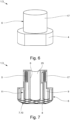
- Fig. 1 shows a first embodiment of a coil arrangement 1 for a flowmeter 2, with a flowmeter 2 in parts in the Fig. 7 and 8th is shown.
- the coil arrangement 1 has a coil 3, which has a coil body 4 and at least one coil turn 5 made of an electrically conductive material.
- the coil 3 has several coil turns 5 made of copper.
- the bobbin 4 is made of a ceramic material.
- the coil former 4 is manufactured using an additive manufacturing process, in the present case using stereolithography.
- the bobbin 4 is designed in its interior 11 delimited by the bobbin walls 6 in such a way that the material in the interior 11 of the bobbin 4 is arranged in an irregular structure.
- the bobbin 4 has both areas with an open porosity and areas with a closed porosity.
- the realization of such structures in the interior 11 of the coil former 4 is easily possible. In this way, material can be saved in particular, so that the coil bodies 4 and thus the coil arrangements 1 can be produced more cost-effectively.
- such coil arrangements 1 have a reduced weight compared to coil arrangements 1 with solid coil formers 4.
- Fig. 2 shows a second embodiment of a coil arrangement 1, which also has a coil 3.
- the one in Fig. 2 Coil body 2 shown is made of a ceramic material and was manufactured using an additive manufacturing process, in this case using sinter lithography.
- the bobbin 4 does not have an irregular structure in its interior 11 delimited by the bobbin walls 6, but rather has a regular structure 7.
- the regular structure 7 is based on a two-dimensional honeycomb grid 8, which was then pulled up in the third spatial direction to form columns 9.
- the regular structure 7 in the present case is realized by a column structure 10.
- All coil formers 4 shown in the figures are manufactured using an additive manufacturing process and consist of a ceramic material.
- Another embodiment of a coil arrangement 1 is in Fig. 3 shown.
- the bobbin 4 is hollow from the inside. No ceramic material is therefore arranged in the interior 11 delimited by the bobbin walls 6.
- the coil windings 5 are made of copper and wound around the ceramic coil former 4.
- the 5a and 5b show an embodiment in which the regular structure 7 in the interior 11 of the ceramic coil former 4 is realized by a lattice structure 12.
- a three-dimensional honeycomb grid 13 is realized by webs 14 connecting the grid points of the honeycomb grid 13.
- the material required is further reduced. Due to the grid structure 12, the bobbin 4 nevertheless has sufficient mechanical stability.
- FIG. 4 Another embodiment of a coil arrangement 1 is in Fig. 4 shown.
- the coil arrangement 1 shown here is identical in its interior 11 to that in Fig. 2 illustrated embodiment, so has an ordered structure 7 in the form of a column structure 10.
- the embodiment shown has the in Fig. 4 illustrated embodiment has an undercut 15 in which the coil turns 5 are at least partially arranged.
- the realization of an undercut 15 in the ceramic bobbin 4 is easily possible due to the production of the bobbin 4 using an additive manufacturing process. Because the coil turns 5 are at least partially arranged in the undercut 15, the undercut 15 forms protection against the outer space 16 of the coil arrangement 1.
- the coil arrangement 1 shown has a casing 17 in addition to the coil body 4 and the invisible coil turns 5.
- Both the bobbin 4 and the casing 17 are made of a ceramic material and made using additive manufacturing.
- the casing 17 is arranged in the area of the coil windings 5 and thus forms a closure to the external space 16.
- the coil windings 5 are completely insulated from the external space 16 by the casing 17.
- the bobbin 4 is solid in its interior 11.
- Fig. 7 also shows a representation of a coil arrangement, which is also like that in Fig. 6
- the coil arrangement shown has a casing 17.
- Fig. 7 shows a cross section through the coil arrangement 1, so that in Fig. 7 It is particularly clear that the casing 17 is formed in one piece with the coil body 4 and also completely delimits the coil turns 5 from the outer space 16.
- Such a coil arrangement 1 can be realized particularly advantageously due to additive manufacturing.
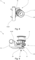
- the coil arrangements 1 have a fastening element 18 for fastening the coil arrangements 1 to a component 19 of the flow measuring device 2.
- the coil arrangements 1 are attached to the measuring tube 20 of the flow measuring device 2, in this case a Coriolis flow measuring device.
- the fastening element 18 is made of a ceramic material and is also manufactured using an additive manufacturing process.
- the fastening element 18 is formed in one piece with the bobbin 4. In particular, the fastening element 18 and the bobbin 4 were additively manufactured in a common printing step.
- the fastening element 18 is the one in Fig. 9 illustrated embodiment realized as a separate component.
- the bobbin 4 and the fastening element 18 are connected to one another by additional connecting means 21.
- this is implemented in such a way that the fastening element 18 has a recess 22 through which a connecting rod 23 connected to the bobbin is passed.
- the coil former 4 has a channel 25 for guiding electrical connections.
- Fig. 6 Another special feature is that in Fig. 6 coil arrangement 1 shown.
- the at least one coil turn 5, which is arranged behind the casing 17 and is therefore not visible, is made of an electrically conductive ceramic and has also been manufactured using an additive manufacturing process.
- Fig. 10a shows a block diagram of a first variant of a first method 100 for producing a coil arrangement, as shown, for example, in Fig. 1 is shown.
- a provision step 101 a 3D model of at least the bobbin is provided.
- the bobbin is manufactured from a ceramic material using an additive manufacturing process using the 3D model and in a winding step 103 the at least one coil turn is arranged around the bobbin.
- a 3D model of the bobbin is provided in the provision step 101, in which the bobbin is at least partially hollow in its interior, in that the material inside the bobbin is at least partially arranged in an irregular structure .
- Fig. 10b shows a block diagram of a second variant of a first method 100 for producing a coil arrangement, as shown in Fig. 1 is shown.
- a 3D model of at least the bobbin is also initially provided in a provision step 101.
- the at least one coil turn is now provided in a coil turn provision step 103 '.
- the bobbin is at least partially printed into the interior of the coil winding provided using an additive manufacturing process based on the 3D model made of a ceramic material. This is done in such a way that the coil winding provided is arranged around the printed coil body.
- Fig. 11 shows a second embodiment of a method 100' for producing a coil arrangement.
- a 3D model of the bobbin is also provided in a provision step 100.
- a 3D model of the bobbin is provided, in which the bobbin is at least partially inside is hollow, in that the material inside the bobbin is at least partially arranged in a regular structure.
- a coil turn providing step 104 a 3D model of the at least one coil turn is provided.
- the at least one coil winding is manufactured from an electrically conductive material, in the present case from an electrically conductive ceramic, using an additive manufacturing process based on the provided 3D model.
- the bobbin printing step 102 is divided into at least a first partial printing step 102' and a second partial printing step 102".
- a first bobbin part is manufactured in the first partial printing step 102'.
- the winding step 103 the at least a coil turn is arranged around the first bobbin part and then the second bobbin part is manufactured in the second partial printing step 102".
- the first bobbin part and the second bobbin part are manufactured in such a way that they are formed in one piece, that is to say they are inextricably connected to one another.
- Fig. 12 shows a block diagram of a method 100" for producing a coil arrangement, in which the coil arrangement has both a sheath that at least partially closes the coil arrangement towards the outside and a fastening element for fastening the coil arrangement to a component of a flow measuring device.
- the provision step 101 in addition to the 3D -Model of the bobbin also provides a 3D model of the casing and a 3D model of the fastening element.
- the first sub-step 102 'of the bobbin printing step 102 is then carried out at the same time as a casing printing step 106.
- the casing is produced using an additive manufacturing process, in the present case i.e.
- the fastening element printing step 107 the fastening element is manufactured from a ceramic material using an additive manufacturing process based on the 3D model. In the present case, the same process and the same material are used as for the production of the bobbin and the casing. In the illustrated method, the fastener printing step 107 occurs independently.
- the fastener pressure step 107, the bobbin pressure step 102 and the sheath pressure step 106 are carried out at the same time, such that the fastener, the bobbin and the sheath are realized in one piece.
Landscapes
- Physics & Mathematics (AREA)
- Fluid Mechanics (AREA)
- General Physics & Mathematics (AREA)
- Engineering & Computer Science (AREA)
- Power Engineering (AREA)
- Electromagnetism (AREA)
- Manufacturing & Machinery (AREA)
- Measuring Volume Flow (AREA)
- Manufacturing Cores, Coils, And Magnets (AREA)
Applications Claiming Priority (1)
| Application Number | Priority Date | Filing Date | Title |
|---|---|---|---|
| DE202022108431 | 2022-04-07 |
Publications (2)
| Publication Number | Publication Date |
|---|---|
| EP4257933A1 true EP4257933A1 (fr) | 2023-10-11 |
| EP4257933B1 EP4257933B1 (fr) | 2025-11-12 |
Family
ID=87891032
Family Applications (1)
| Application Number | Title | Priority Date | Filing Date |
|---|---|---|---|
| EP23165953.3A Active EP4257933B1 (fr) | 2022-04-07 | 2023-03-31 | Ensemble bobine pour un débitmètre et procédé de fabrication d'un ensemble bobine |
Country Status (1)
| Country | Link |
|---|---|
| EP (1) | EP4257933B1 (fr) |
Citations (2)
| Publication number | Priority date | Publication date | Assignee | Title |
|---|---|---|---|---|
| DE102017207663A1 (de) * | 2017-05-08 | 2018-11-08 | Audi Ag | Verfahren zur Herstellung einer Spulenanordnung |
| WO2022031328A1 (fr) * | 2020-08-06 | 2022-02-10 | Micro Motion, Inc. | Transducteur destiné à un appareil de mesure de fluide vibrant |
-
2023
- 2023-03-31 EP EP23165953.3A patent/EP4257933B1/fr active Active
Patent Citations (2)
| Publication number | Priority date | Publication date | Assignee | Title |
|---|---|---|---|---|
| DE102017207663A1 (de) * | 2017-05-08 | 2018-11-08 | Audi Ag | Verfahren zur Herstellung einer Spulenanordnung |
| WO2022031328A1 (fr) * | 2020-08-06 | 2022-02-10 | Micro Motion, Inc. | Transducteur destiné à un appareil de mesure de fluide vibrant |
Non-Patent Citations (1)
| Title |
|---|
| ANONYMOUS: "3D-Druck", WIKIPEDIA, 26 January 2017 (2017-01-26), pages 1 - 9, XP055579281, Retrieved from the Internet <URL:https://de.wikipedia.org/w/index.php?title=3D-Druck&oldid=162016514> [retrieved on 20190409] * |
Also Published As
| Publication number | Publication date |
|---|---|
| EP4257933B1 (fr) | 2025-11-12 |
Similar Documents
| Publication | Publication Date | Title |
|---|---|---|
| DE102013114352A1 (de) | Gleichtaktfilter | |
| EP2155418A1 (fr) | Procédé de fabrication d'une pièce coulée, moule de coulée et pièce coulée fabriquée avec ce dernier | |
| DE102019100007B4 (de) | Gleichtaktfilter | |
| EP2625430A1 (fr) | Procédé de fabrication d'un carter de turbocompresseur | |
| DE102019100013A1 (de) | Gleichtaktfilter | |
| WO2012076644A2 (fr) | Procédé de fabrication d'un stator | |
| DE102015105143B4 (de) | Luftreinigerbaugruppe für Kraftfahrzeuge mit einem Befestigungs- / Isolierungsmerkmal sowie Verfahren zum Betreiben solch einer Luftreinigerbaugruppe | |
| EP2796726A1 (fr) | Élément de stator pour un étage de pompe Holweck, pompe à vide dotée d'un étage de pompe Holweck et procédé de fabrication d'un élément de stator pour un étage de pompe de Holweck | |
| WO1992016955A1 (fr) | Procede de production de bobines en resine de coulee et bobines en resine de coulee ainsi produites | |
| EP4257933B1 (fr) | Ensemble bobine pour un débitmètre et procédé de fabrication d'un ensemble bobine | |
| DE102022108431A1 (de) | Spulenanordnung für ein Durchflussmessgerät und Verfahren zum Herstellen einer Spulenanordnung | |
| WO2020038680A1 (fr) | Stator pour machine électrique | |
| EP3853983B1 (fr) | Fabrication d'une spirale, moule permanent pour une spirale et spirale associée | |
| EP3093681B1 (fr) | Conception modulaire pour plusieurs bobines à gradient ou de shim | |
| DE102018215987A1 (de) | Herstellung einer Wendel, Dauerform für eine Wendel sowie Wendel | |
| DE102018106725A1 (de) | Verfahren zur Herstellung einer Gussform zum Einfüllen von Schmelze sowie Gussform | |
| EP3805475B1 (fr) | Support pour treillis | |
| EP2527258B1 (fr) | Procédé de fabrication d'un bras pour véhicule spatial | |
| EP1313938A1 (fr) | Moteur-fusee a segments | |
| EP1815554B1 (fr) | Lignes de couplage pour un filtre yig ou un oscillateur yig et procede pour produire ces lignes de couplage | |
| DE102022129881B4 (de) | Struktur zur Schallabsorption | |
| EP3772546B1 (fr) | Fabrication d'une structure au moyen d'un procédé de pulvérisation de gaz froid | |
| EP1619480A1 (fr) | Débitmètre magnéto-inductif et procédé pour la fabrication d'un conduit de mesure pour un débitmètre magnéto-inductif | |
| DE102019129747A1 (de) | Verfahren zur Herstellung einer Messeinheit und Messeinheit | |
| DE10024335A1 (de) | Ohmscher Spannungsfühler |
Legal Events
| Date | Code | Title | Description |
|---|---|---|---|
| PUAI | Public reference made under article 153(3) epc to a published international application that has entered the european phase |
Free format text: ORIGINAL CODE: 0009012 |
|
| STAA | Information on the status of an ep patent application or granted ep patent |
Free format text: STATUS: THE APPLICATION HAS BEEN PUBLISHED |
|
| AK | Designated contracting states |
Kind code of ref document: A1 Designated state(s): AL AT BE BG CH CY CZ DE DK EE ES FI FR GB GR HR HU IE IS IT LI LT LU LV MC ME MK MT NL NO PL PT RO RS SE SI SK SM TR |
|
| STAA | Information on the status of an ep patent application or granted ep patent |
Free format text: STATUS: REQUEST FOR EXAMINATION WAS MADE |
|
| 17P | Request for examination filed |
Effective date: 20240227 |
|
| RBV | Designated contracting states (corrected) |
Designated state(s): AL AT BE BG CH CY CZ DE DK EE ES FI FR GB GR HR HU IE IS IT LI LT LU LV MC ME MK MT NL NO PL PT RO RS SE SI SK SM TR |
|
| STAA | Information on the status of an ep patent application or granted ep patent |
Free format text: STATUS: EXAMINATION IS IN PROGRESS |
|
| 17Q | First examination report despatched |
Effective date: 20250207 |
|
| GRAP | Despatch of communication of intention to grant a patent |
Free format text: ORIGINAL CODE: EPIDOSNIGR1 |
|
| STAA | Information on the status of an ep patent application or granted ep patent |
Free format text: STATUS: GRANT OF PATENT IS INTENDED |
|
| INTG | Intention to grant announced |
Effective date: 20250702 |
|
| GRAS | Grant fee paid |
Free format text: ORIGINAL CODE: EPIDOSNIGR3 |
|
| GRAA | (expected) grant |
Free format text: ORIGINAL CODE: 0009210 |
|
| STAA | Information on the status of an ep patent application or granted ep patent |
Free format text: STATUS: THE PATENT HAS BEEN GRANTED |
|
| AK | Designated contracting states |
Kind code of ref document: B1 Designated state(s): AL AT BE BG CH CY CZ DE DK EE ES FI FR GB GR HR HU IE IS IT LI LT LU LV MC ME MK MT NL NO PL PT RO RS SE SI SK SM TR |
|
| REG | Reference to a national code |
Ref country code: CH Ref legal event code: F10 Free format text: ST27 STATUS EVENT CODE: U-0-0-F10-F00 (AS PROVIDED BY THE NATIONAL OFFICE) Effective date: 20251112 Ref country code: GB Ref legal event code: FG4D Free format text: NOT ENGLISH |
|
| REG | Reference to a national code |
Ref country code: IE Ref legal event code: FG4D Free format text: LANGUAGE OF EP DOCUMENT: GERMAN |
|
| REG | Reference to a national code |
Ref country code: DE Ref legal event code: R096 Ref document number: 502023002179 Country of ref document: DE |
|
| P01 | Opt-out of the competence of the unified patent court (upc) registered |
Free format text: CASE NUMBER: UPC_APP_0012905_4257933/2025 Effective date: 20251111 |
|
| REG | Reference to a national code |
Ref country code: NL Ref legal event code: MP Effective date: 20251112 |
|
| REG | Reference to a national code |
Ref country code: CH Ref legal event code: U11 Free format text: ST27 STATUS EVENT CODE: U-0-0-U10-U11 (AS PROVIDED BY THE NATIONAL OFFICE) Effective date: 20260401 |
|
| PG25 | Lapsed in a contracting state [announced via postgrant information from national office to epo] |
Ref country code: ES Free format text: LAPSE BECAUSE OF FAILURE TO SUBMIT A TRANSLATION OF THE DESCRIPTION OR TO PAY THE FEE WITHIN THE PRESCRIBED TIME-LIMIT Effective date: 20251112 |
|
| REG | Reference to a national code |
Ref country code: LT Ref legal event code: MG9D |
|
| PG25 | Lapsed in a contracting state [announced via postgrant information from national office to epo] |
Ref country code: NO Free format text: LAPSE BECAUSE OF FAILURE TO SUBMIT A TRANSLATION OF THE DESCRIPTION OR TO PAY THE FEE WITHIN THE PRESCRIBED TIME-LIMIT Effective date: 20260212 |
|
| PG25 | Lapsed in a contracting state [announced via postgrant information from national office to epo] |
Ref country code: FI Free format text: LAPSE BECAUSE OF FAILURE TO SUBMIT A TRANSLATION OF THE DESCRIPTION OR TO PAY THE FEE WITHIN THE PRESCRIBED TIME-LIMIT Effective date: 20251112 Ref country code: HR Free format text: LAPSE BECAUSE OF FAILURE TO SUBMIT A TRANSLATION OF THE DESCRIPTION OR TO PAY THE FEE WITHIN THE PRESCRIBED TIME-LIMIT Effective date: 20251112 |
|
| PG25 | Lapsed in a contracting state [announced via postgrant information from national office to epo] |
Ref country code: NL Free format text: LAPSE BECAUSE OF FAILURE TO SUBMIT A TRANSLATION OF THE DESCRIPTION OR TO PAY THE FEE WITHIN THE PRESCRIBED TIME-LIMIT Effective date: 20251112 |
|
| PG25 | Lapsed in a contracting state [announced via postgrant information from national office to epo] |
Ref country code: RS Free format text: LAPSE BECAUSE OF FAILURE TO SUBMIT A TRANSLATION OF THE DESCRIPTION OR TO PAY THE FEE WITHIN THE PRESCRIBED TIME-LIMIT Effective date: 20260212 |
|
| PG25 | Lapsed in a contracting state [announced via postgrant information from national office to epo] |
Ref country code: IS Free format text: LAPSE BECAUSE OF FAILURE TO SUBMIT A TRANSLATION OF THE DESCRIPTION OR TO PAY THE FEE WITHIN THE PRESCRIBED TIME-LIMIT Effective date: 20260312 |
|
| PGFP | Annual fee paid to national office [announced via postgrant information from national office to epo] |
Ref country code: FR Payment date: 20260323 Year of fee payment: 4 |
|
| PG25 | Lapsed in a contracting state [announced via postgrant information from national office to epo] |
Ref country code: PT Free format text: LAPSE BECAUSE OF FAILURE TO SUBMIT A TRANSLATION OF THE DESCRIPTION OR TO PAY THE FEE WITHIN THE PRESCRIBED TIME-LIMIT Effective date: 20260312 |
|
| PG25 | Lapsed in a contracting state [announced via postgrant information from national office to epo] |
Ref country code: PL Free format text: LAPSE BECAUSE OF FAILURE TO SUBMIT A TRANSLATION OF THE DESCRIPTION OR TO PAY THE FEE WITHIN THE PRESCRIBED TIME-LIMIT Effective date: 20251112 |
|
| PG25 | Lapsed in a contracting state [announced via postgrant information from national office to epo] |
Ref country code: LV Free format text: LAPSE BECAUSE OF FAILURE TO SUBMIT A TRANSLATION OF THE DESCRIPTION OR TO PAY THE FEE WITHIN THE PRESCRIBED TIME-LIMIT Effective date: 20251112 |