EP4257916A1 - Generativ gefertigtes montagefreies werkzeug zur wartung eines fahrzeugmotors - Google Patents
Generativ gefertigtes montagefreies werkzeug zur wartung eines fahrzeugmotors Download PDFInfo
- Publication number
- EP4257916A1 EP4257916A1 EP22166482.4A EP22166482A EP4257916A1 EP 4257916 A1 EP4257916 A1 EP 4257916A1 EP 22166482 A EP22166482 A EP 22166482A EP 4257916 A1 EP4257916 A1 EP 4257916A1
- Authority
- EP
- European Patent Office
- Prior art keywords
- tool
- bar
- housing
- lock element
- chamber
- Prior art date
- Legal status (The legal status is an assumption and is not a legal conclusion. Google has not performed a legal analysis and makes no representation as to the accuracy of the status listed.)
- Granted
Links
Images


Classifications
-
- G—PHYSICS
- G01—MEASURING; TESTING
- G01B—MEASURING LENGTH, THICKNESS OR SIMILAR LINEAR DIMENSIONS; MEASURING ANGLES; MEASURING AREAS; MEASURING IRREGULARITIES OF SURFACES OR CONTOURS
- G01B5/00—Measuring arrangements characterised by the use of mechanical techniques
- G01B5/003—Measuring of motor parts
-
- B—PERFORMING OPERATIONS; TRANSPORTING
- B23—MACHINE TOOLS; METAL-WORKING NOT OTHERWISE PROVIDED FOR
- B23P—METAL-WORKING NOT OTHERWISE PROVIDED FOR; COMBINED OPERATIONS; UNIVERSAL MACHINE TOOLS
- B23P15/00—Making specific metal objects by operations not covered by a single other subclass or a group in this subclass
-
- B—PERFORMING OPERATIONS; TRANSPORTING
- B33—ADDITIVE MANUFACTURING TECHNOLOGY
- B33Y—ADDITIVE MANUFACTURING, i.e. MANUFACTURING OF THREE-DIMENSIONAL [3D] OBJECTS BY ADDITIVE DEPOSITION, ADDITIVE AGGLOMERATION OR ADDITIVE LAYERING, e.g. BY 3D PRINTING, STEREOLITHOGRAPHY OR SELECTIVE LASER SINTERING
- B33Y10/00—Processes of additive manufacturing
-
- B—PERFORMING OPERATIONS; TRANSPORTING
- B33—ADDITIVE MANUFACTURING TECHNOLOGY
- B33Y—ADDITIVE MANUFACTURING, i.e. MANUFACTURING OF THREE-DIMENSIONAL [3D] OBJECTS BY ADDITIVE DEPOSITION, ADDITIVE AGGLOMERATION OR ADDITIVE LAYERING, e.g. BY 3D PRINTING, STEREOLITHOGRAPHY OR SELECTIVE LASER SINTERING
- B33Y80/00—Products made by additive manufacturing
-
- G—PHYSICS
- G01—MEASURING; TESTING
- G01B—MEASURING LENGTH, THICKNESS OR SIMILAR LINEAR DIMENSIONS; MEASURING ANGLES; MEASURING AREAS; MEASURING IRREGULARITIES OF SURFACES OR CONTOURS
- G01B3/00—Measuring instruments characterised by the use of mechanical techniques
- G01B3/22—Feeler-pin gauges, e.g. dial gauges
- G01B3/28—Depth gauges
-
- G—PHYSICS
- G01—MEASURING; TESTING
- G01B—MEASURING LENGTH, THICKNESS OR SIMILAR LINEAR DIMENSIONS; MEASURING ANGLES; MEASURING AREAS; MEASURING IRREGULARITIES OF SURFACES OR CONTOURS
- G01B5/00—Measuring arrangements characterised by the use of mechanical techniques
- G01B5/14—Measuring arrangements characterised by the use of mechanical techniques for measuring distance or clearance between spaced objects or spaced apertures
-
- B—PERFORMING OPERATIONS; TRANSPORTING
- B22—CASTING; POWDER METALLURGY
- B22F—WORKING METALLIC POWDER; MANUFACTURE OF ARTICLES FROM METALLIC POWDER; MAKING METALLIC POWDER; APPARATUS OR DEVICES SPECIALLY ADAPTED FOR METALLIC POWDER
- B22F10/00—Additive manufacturing of workpieces or articles from metallic powder
- B22F10/20—Direct sintering or melting
- B22F10/28—Powder bed fusion, e.g. selective laser melting [SLM] or electron beam melting [EBM]
-
- B—PERFORMING OPERATIONS; TRANSPORTING
- B22—CASTING; POWDER METALLURGY
- B22F—WORKING METALLIC POWDER; MANUFACTURE OF ARTICLES FROM METALLIC POWDER; MAKING METALLIC POWDER; APPARATUS OR DEVICES SPECIALLY ADAPTED FOR METALLIC POWDER
- B22F5/00—Manufacture of workpieces or articles from metallic powder characterised by the special shape of the product
- B22F2005/002—Tools other than cutting tools
-
- F—MECHANICAL ENGINEERING; LIGHTING; HEATING; WEAPONS; BLASTING
- F01—MACHINES OR ENGINES IN GENERAL; ENGINE PLANTS IN GENERAL; STEAM ENGINES
- F01L—CYCLICALLY OPERATING VALVES FOR MACHINES OR ENGINES
- F01L2301/00—Using particular materials
-
- F—MECHANICAL ENGINEERING; LIGHTING; HEATING; WEAPONS; BLASTING
- F01—MACHINES OR ENGINES IN GENERAL; ENGINE PLANTS IN GENERAL; STEAM ENGINES
- F01L—CYCLICALLY OPERATING VALVES FOR MACHINES OR ENGINES
- F01L2303/00—Manufacturing of components used in valve arrangements
-
- F—MECHANICAL ENGINEERING; LIGHTING; HEATING; WEAPONS; BLASTING
- F01—MACHINES OR ENGINES IN GENERAL; ENGINE PLANTS IN GENERAL; STEAM ENGINES
- F01L—CYCLICALLY OPERATING VALVES FOR MACHINES OR ENGINES
- F01L2303/00—Manufacturing of components used in valve arrangements
- F01L2303/01—Tools for producing, mounting or adjusting, e.g. some part of the distribution
Definitions
- the disclosure relates to an additive manufactured assembly-free tool for maintenance of an engine in a vehicle.
- Fig.1 (a) shows a special setting tool 10 with a series number 88800031 which is used in maintenance of engines in heavy duty trucks, e.g. when checking for proper camshaft position sensor clearance to determine if shims are required for sensor depth.
- the special setting tool 10 is used to measure the distance between two components, e.g. a tooth of a camshaft toothed wheel and a timing gear cover, in an engine.
- the distance or gap between the two components is indicated by edges shown outside one end of the tool 10. Based on the measured result, different layers of shims will be added accordingly in the following maintenance step. For example, if no edge is shown outside the tool 10, as indicated in Fig.
- Fig. 1 (e) shows a cross-section view of the original setting tool 10.
- the original setting tool 10 has four parts, a first part 11: an outer housing; a second part 12: an inner part; a third part 13: a spring pin; a fourth part 14: a screw. After the four parts are manufactured separately, the assembly process is firstly, inserting the second part 12 into the first part 11, secondly, inserting the third part 13 through the holes in the first 11 and second parts 12, then screwing in the fourth part 14.
- the spring pin 13 is to hold the second part 12 so that it is not falling off from the first part 11.
- the spring pin 13 is made of spring steel and is very small and easy to be lost.
- the original setting tool 10 is using the force of the screw 14 to secure the position of the inner part 12. There is a possibility of slippery during operation and also a wear problem on the inner part 12.
- An object of the disclosure is to provide a setting tool for maintenance of an engine in a vehicle with improved performance and simplified usage.
- the object is achieved by an assembly-free tool for maintenance of an engine in a vehicle according to claim 1.
- the tool comprises a bar extending in an axial direction and having a first portion with a first end and a second portion with a second end.
- the tool further comprises a housing surrounding the first portion of the bar.
- the bar is axially translatable in relation to the housing.
- the housing comprises an embedded locking structure for holding the bar in a locking position such that the movement of the bar in the axial direction is stopped.
- the bar, the housing and the locking structure are retained as one unit such that they are non-detachable from each other.
- the tool according to embodiments herein consolidates four parts of the original tool into one unit and can use the same type of steel material for the whole tool instead of using different steel material which will simplify the manufacturing process. That is the tool according to embodiments herein is self-assembled and consolidated without using the small spring pin, which will make the maintainability of the tool better and the usage of the tool simpler compared to the original tool.
- the embedded locking structure may comprise a chamber and a lock element.
- the chamber is adapted to hold the lock element in an unlocking position and a locking position.
- the lock element is axially displaceable and rotatable within the chamber between the unlocking position and locking position.
- the lock element may be a pin with a protrusion bar i.e., a 'rotate-locking' pin or a screw.
- the bar may comprise a jagged structure adjacent to the first end of the bar.
- the jagged structure is adapted to encounter the tip of the lock element when the lock element is in the locking position.
- the bar may comprise a retaining structure at the first portion of the bar for retaining the bar in the housing such that the bar and housing are non-detachable from each other.
- the bar may comprise two or more markers at a position of the first portion of the bar spaced apart from the first end of the bar.
- the markers are for indicting measured distance.
- the tool according to embodiments herein is configured to be manufactured by 3D-printing as one unit during a single additive manufacturing process.
- the tool may be made of stainless steel, tool steel or titanium alloy.
- any one or all of the bar the housing and the lock element may have a hollow structure with or without strengthening ribs.
- the object is achieved by a method for manufacturing the tool described above according to claim 13.
- the method comprises printing the whole tool by using a 3D-printing machine on a building plate starting from the first end of the bar, a first end of the housing, a first end of the embedded locking structure and continuing up to the second end of the bar.
- the bar, the housing and the embedded locking structure are 3D-printed as one unit during a single manufacturing process.
- the method further comprises separating the whole tool as one unit from the building plate.
- the optional retaining structure and jagged structure, the optional markers, the embedded locking structure with the pin and protrusion bar and the chamber with two surfaces, or the embedded locking structure with the chamber with threads and the screw are directly 3D-printed during the same single manufacturing process, such that the whole tool is 3D-printed as one unit during the single manufacturing process.
- the tool is designed in a way that it can be metal 3D-printed without support structures and thus it can be used directly after printing without additional machining steps.
- the manufacturing process for the tool is therefore simplified compared to that of the original tool and a decrease in price can be expected.
- the tool is self-assembled and does not need assembly process before usage. That is the tool according to embodiments herein is an assembly-free tool which makes it easy to use and operate, the service maintenance time is therefore shortened, and maintainability of the tool is improved.
- an assembly-free tool for maintenance of an engine in a vehicle e.g. measuring distance between two components in the engine of the vehicle, is provided according to embodiments herein.
- Three dimensions (3D) printing or additive manufacturing (AM) is a construction of a three-dimensional object from a computer-aided design (CAD) model or a digital 3D model.
- 3D-printing or AM can be used for producing everything, such as spare parts, prototypes etc.
- Products are manufactured layer by layer and are close to their final shape, thereby reducing wastage.
- Materials such as metals, polymers, wood flour, biocompatible materials, sand and composites are used at present.
- 3D-printing or AM paves a way for manufacturing on demand for many industries.
- Embodiments herein take the advantages of the 3D-printing or AM and provide an assembly-free tool for maintenance of an engine in a vehicle.
- the assembly-free tool according to embodiments herein consolidates four parts of the original tool 10 into one unit and can be additive manufactured by a single manufacturing process.
- the assembly-free tool according to embodiments herein can use the same type of steel material for the whole tool instead of using different steel materials which will simplify the manufacturing process.
- the tool according to embodiments herein is an assembly-free tool which makes it easy to use and operate, the service maintenance time for an engine is therefore shortened, and maintainability of the tool is improved.
- the assembly-free tool according to embodiments herein can be applied in maintenance of engines in heavy-duty vehicles, such as trucks.
- heavy-duty vehicles such as trucks.
- the disclosure will be described with respect to an engine in a heavy duty truck, the disclosure is not restricted to this particular engine, but may also be used in other engines of vehicles such as buses and medium duty vehicles etc.
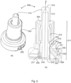
- Fig. 2 (a) shows a perspective view of an assembly-free tool 200 according to embodiments herein for maintenance of an engine in a vehicle.
- Fig. 2 (b) shows a cross-section view of the tool 200.
- the tool 200 comprises a bar 210 extending in an axial A direction and having a first portion 211 with a first end 212 and a second portion 213 with a second end 214.
- the tool 200 further comprise a housing 220 surrounding the first portion 211 of the bar 210.
- the bar 210 is axially translatable in relation to the housing 220.
- the housing 220 comprises an embedded locking structure 230 for holding the bar 210 in a locking position to stop the movement of the bar 210 in the axial A direction.
- the bar 210, the housing 220 and the locking structure 230 are retained as one unit such that they are non-detachable from each other.
- the housing 220 may have any kind of shape. To have the same functionality as the original setting tool, the size and shape of the housing 220 are the same as the outer housing of the original setting tool.
- the embedded locking structure 230 may comprise a chamber 231 and a lock element 232.
- the chamber 231 is adapted to hold the lock element 232 in an unlocking position and a locking position.
- the lock element 232 is axially displaceable and rotatable within the chamber 231 between the unlocking position and locking position.
- the embedded locking structure 230 shown in Fig.2 (b) is an example embodiment of the embedded locking structure 230, where the lock element 232 is a pin with a protrusion bar 233.
- This embedded locking structure 230 is further shown in Fig.3 , where (a) shows a cross-section view of the embedded locking structure 230 when the lock element 232 is in an unlocking position 311, (b) shows a cross-section view of the embedded locking structure 230 when the lock element 232 is in a locking position 312, (c) shows a cross-section view of the embedded locking structure 230 from a certain angel to show the structure of the chamber 231, and (d) shows a top perspective view of the embedded locking structure 230.
- the lock element 232 in this embodiment is a pin with a protrusion bar 233 and the chamber 231, as shown in Fig. 3 (c) , comprises a groove having a first surface 310 to hold the lock element 232 in the unlocking position 311 and a second surface 320 to hold the lock element 232 in the locking position 312.
- the lock element 232 can be pushed along an axial direction indicated by arrow A1 and rotated in a direction indicted by arrow R to the locking position.
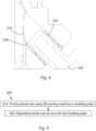
- Fig.4 shows another example embodiment of the embedded locking structure 230, where the lock element 232 is a screw 235 and the chamber 231 comprises threads 237.
- the screw 235 can be rotated and axially translated to the locking position.
- the bar 210 may comprise a jagged structure 215 adjacent to the first end 212 of the bar 210, as shown in Fig. 2(b) , Fig. 3(a) , (b) and Fig.4 .
- the jagged structure 215 is adapted to encounter the tip 236, 238 of the lock element 232, 235 when the lock element 232, 235 is in the locking position 312, as shown in Fig. 3(b) .
- the bar 210 may comprise a retaining structure 216 at the first portion 211 of the bar 210 for retaining the bar 210 in the housing 220 such that the bar 210 and housing 220 are non-detachable from each other.
- the retaining structure 216 may locate at any position within the first portion 211 of the bar 210, e.g. 1-3 cm from the first end 212 of the bar 210.
- the retaining structure 216 may be any shape, e.g. a protrusion around the bar 210 as shown in Fig.2 (b) .
- the bar 210 may comprise two or more markers 217 at a position 218 of the first portion of the bar 210 spaced apart from the first end 212 of the bar 210, as shown in Fig.2 (b) .
- the two or more markers 217 may be gaps.
- the two or more markers 217 is for indicating measured distance between two components.
- any one or all of the bar 210, the housing 220 and the lock element 230 may have a hollow structure.
- any one or all of the bar 210, the housing 220 and the lock element 230 may comprise strengthening ribs.
- the tool 200 is configured to be manufactured by 3D-printing as one unit during a single additive manufacturing process.
- the tool 200 may be made of stainless steel, tool steel or titanium alloy by 3D printing.
- Fig. 5 shows a flow chart of a method 500 for manufacturing the tool 200.
- the method 500 comprises the following actions.
- the bar 210, the housing 220 and the embedded locking structure 230 are 3D-printed as one unit during a single manufacturing process.
- the optional retaining structure 216 and jagged structure 215, the optional markers 217, the optional pin 232 with protrusion bar 233 and the chamber 231 with two surfaces or the optional chamber 231 with threads and the screw 235 are directly 3D-printed during the same single manufacturing process, such that the whole tool 200 is 3D-printed as one unit during the single manufacturing process.
- important face-down surfaces e.g. surface 241 of the chamber 231, surface 242 of the lock element 232, surface 243 of the retaining structure 216 on the bar 210, etc., all are designed such that they can be printed layer by layer without extra support structures during 3D printing.
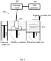
- Fig.6 is a simplified cross-section view of an example 3D printing machine 600, which may be used to manufacture the tool 200 by Selective Laser Melting (SLM) process.
- SLM Selective Laser Melting
- a product is formed by selectively melting successive layers of powder by the interaction of a laser beam.
- the powder material is heated and, if sufficient power is applied, melts and forms a liquid pool.
- the molten pool solidifies and cools down quickly, and the consolidated material starts to form the product.
- the building platform is lowered by an amount equal to the layer thickness and a new layer of powder is deposited. This process is repeated until the product is completed.
- metal powder 610 in a dispenser plate 620 is heated close to its melting point and spread by a power recoater 630 on a building plate 640.
- a scanning head 650 connected to a laser generator 660 draws or scans a cross section of a part, e.g. the tool 200, into the powder material, i.e. the cross section of the first end 212 of the bar 210, the first end 223 of the housing 220 and the first end 234 of the embedded locking structure 230 are formed by the laser beam.
- the building plate 640 is lowered corresponding to one layer thickness which is approximately 0.1mm, after which the process is repeated until the 3D tool 100 is completed.
- a collecting plate 670 is used for collecting the rest of un-melted metal powder.
- the SLM may be used to selectively melt nickel-based superalloys, Ti-based alloys, Al-based alloys and Nb-based alloys to fabricate components and structures for automobile and aerospace application.
- the usage of the tool 200 is similar to the original setting tool 10:
- advantages and improved performances of the tool 200 according to embodiments herein may include and not limited to the following:
Landscapes
- Engineering & Computer Science (AREA)
- Physics & Mathematics (AREA)
- General Physics & Mathematics (AREA)
- Chemical & Material Sciences (AREA)
- Manufacturing & Machinery (AREA)
- Materials Engineering (AREA)
- Plasma & Fusion (AREA)
- Mechanical Engineering (AREA)
- Powder Metallurgy (AREA)
Priority Applications (2)
| Application Number | Priority Date | Filing Date | Title |
|---|---|---|---|
| EP22166482.4A EP4257916B1 (de) | 2022-04-04 | 2022-04-04 | Generativ gefertigtes montagefreies werkzeug zur wartung eines fahrzeugmotors |
| US18/295,348 US12601580B2 (en) | 2022-04-04 | 2023-04-04 | Additive manufactured assembly-free tool for maintenance of vehicle engine |
Applications Claiming Priority (1)
| Application Number | Priority Date | Filing Date | Title |
|---|---|---|---|
| EP22166482.4A EP4257916B1 (de) | 2022-04-04 | 2022-04-04 | Generativ gefertigtes montagefreies werkzeug zur wartung eines fahrzeugmotors |
Publications (3)
| Publication Number | Publication Date |
|---|---|
| EP4257916A1 true EP4257916A1 (de) | 2023-10-11 |
| EP4257916B1 EP4257916B1 (de) | 2024-07-03 |
| EP4257916C0 EP4257916C0 (de) | 2024-07-03 |
Family
ID=81324915
Family Applications (1)
| Application Number | Title | Priority Date | Filing Date |
|---|---|---|---|
| EP22166482.4A Active EP4257916B1 (de) | 2022-04-04 | 2022-04-04 | Generativ gefertigtes montagefreies werkzeug zur wartung eines fahrzeugmotors |
Country Status (2)
| Country | Link |
|---|---|
| US (1) | US12601580B2 (de) |
| EP (1) | EP4257916B1 (de) |
Families Citing this family (1)
| Publication number | Priority date | Publication date | Assignee | Title |
|---|---|---|---|---|
| EP4257916B1 (de) * | 2022-04-04 | 2024-07-03 | Volvo Truck Corporation | Generativ gefertigtes montagefreies werkzeug zur wartung eines fahrzeugmotors |
Citations (2)
| Publication number | Priority date | Publication date | Assignee | Title |
|---|---|---|---|---|
| US9255778B2 (en) * | 2012-12-11 | 2016-02-09 | Honda Motor Co., Ltd. | Gauge apparatus having profile assembly |
| WO2019113622A1 (en) * | 2017-12-13 | 2019-06-20 | Dion Michael Johnson | In situ shotcrete depth indicator |
Family Cites Families (3)
| Publication number | Priority date | Publication date | Assignee | Title |
|---|---|---|---|---|
| WO2019073277A1 (en) * | 2017-10-13 | 2019-04-18 | Volvo Truck Corporation | HEAT EXCHANGER AND ADDITIVE HEAT EXCHANGER MANUFACTURING METHOD |
| CA3120796A1 (en) * | 2018-11-21 | 2020-05-28 | MELD Manufacturing Corporation | Hybrid solid-state additive and subtractive manufacturing processes, materials used and parts fabricated with the hybrid processes |
| EP4257916B1 (de) * | 2022-04-04 | 2024-07-03 | Volvo Truck Corporation | Generativ gefertigtes montagefreies werkzeug zur wartung eines fahrzeugmotors |
-
2022
- 2022-04-04 EP EP22166482.4A patent/EP4257916B1/de active Active
-
2023
- 2023-04-04 US US18/295,348 patent/US12601580B2/en active Active
Patent Citations (2)
| Publication number | Priority date | Publication date | Assignee | Title |
|---|---|---|---|---|
| US9255778B2 (en) * | 2012-12-11 | 2016-02-09 | Honda Motor Co., Ltd. | Gauge apparatus having profile assembly |
| WO2019113622A1 (en) * | 2017-12-13 | 2019-06-20 | Dion Michael Johnson | In situ shotcrete depth indicator |
Non-Patent Citations (2)
| Title |
|---|
| 01: "Special Bulletin", 22 June 2011 (2011-06-22), pages 1 - 25, XP055969914, Retrieved from the Internet <URL:https://static.nhtsa.gov/odi/tsbs/2012/SB-10044284-2627.pdf> [retrieved on 20221011] * |
| ANONYMOUS: "ServiceBulletin Mack Trucks Trucks - JustAnswer - ...ww2.justanswer.com/uploads/HE/HeavyEquipmentTech/2013-12...2013/12/09 . ServiceBulletin Mack Trucks, Inc. Greensboro,NCUSA Trucks - [PDF Document]", 1 April 2010 (2010-04-01), XP055969958, Retrieved from the Internet <URL:https://fdocuments.net/document/servicebulletin-mack-trucks-trucks-justanswer-ww2-mack-trucks-inc-greensboroncusa.html?page=1> [retrieved on 20221011] * |
Also Published As
| Publication number | Publication date |
|---|---|
| US20230324160A1 (en) | 2023-10-12 |
| EP4257916B1 (de) | 2024-07-03 |
| EP4257916C0 (de) | 2024-07-03 |
| US12601580B2 (en) | 2026-04-14 |
Similar Documents
| Publication | Publication Date | Title |
|---|---|---|
| EP3580434B1 (de) | Ringförmiges turbinenbauteil und verfahren zu dessen herstellung | |
| Dutta et al. | Science, technology and applications of metals in additive manufacturing | |
| Yang et al. | Additive manufacturing of metals: the technology, materials, design and production | |
| Duda et al. | 3D metal printing technology | |
| Cheah et al. | Rapid prototyping and tooling techniques: a review of applications for rapid investment casting | |
| EP2524750B1 (de) | Verfahren zur Herstellung metallischer Bauteile mit einer Öffnung | |
| Pham et al. | A comparison of rapid prototyping technologies | |
| RU2705841C1 (ru) | Способы получения изделий посредством аддитивного производства | |
| EP2754515B1 (de) | Verfahren zur herstellung von gasturbinenmotorkomponenten mittels additiver herstellungsverfahren. | |
| EP3621758B1 (de) | Verfahren für ein additiv herzustellendes bauteil mit vorbestimmter oberflächenstruktur | |
| EP3658317A1 (de) | Verfahren und vorrichtung für generativ gefertigte exoskelettbasierte transportstrukturen | |
| CA3011463C (en) | Methods for producing forged products and other worked products | |
| WO2008046388A1 (de) | Hochdruckturbinen-rotor und verfahren zur herstellung eines hochdruckturbinen-rotors | |
| US12601580B2 (en) | Additive manufactured assembly-free tool for maintenance of vehicle engine | |
| EP2940340A1 (de) | Drehmomentstift und herstellungsverfahren | |
| DE102014200381A1 (de) | Verfahren für das generative Herstellen eines Turbinenrades mit einem Deckband | |
| US20180029123A1 (en) | Removable support package for additive manufacture | |
| EP3530380A1 (de) | Verfahren zur generativen fertigung von turbinenmotorkomponenten über bindemittelstrahldruck mit ausscheidungsgehärteten gamma-prime-superlegierungen | |
| US11148199B2 (en) | Deposition of metal dies for part fabrication | |
| Kumar | Additive manufacturing advantage | |
| EP4257292A1 (de) | Generativ gefertigtes baugruppenfreies werkzeug für kraftfahrzeuggetriebewartung | |
| EP2869961B1 (de) | Verfahren zum herstellen eines bauteils mit erwärmung der ersten komponente und des zweiten materials auf einer reaktionstemperatur | |
| WO2023011805A1 (de) | Additives herstellungsverfahren mit gepulster bestrahlung für bauteil mit definierter oberflächentextur | |
| Dewidar | Direct and indirect laser sintering of metals | |
| Udroiu | Additive Manufacturing Technologies Used for Superalloys Processing |
Legal Events
| Date | Code | Title | Description |
|---|---|---|---|
| PUAI | Public reference made under article 153(3) epc to a published international application that has entered the european phase |
Free format text: ORIGINAL CODE: 0009012 |
|
| STAA | Information on the status of an ep patent application or granted ep patent |
Free format text: STATUS: THE APPLICATION HAS BEEN PUBLISHED |
|
| AK | Designated contracting states |
Kind code of ref document: A1 Designated state(s): AL AT BE BG CH CY CZ DE DK EE ES FI FR GB GR HR HU IE IS IT LI LT LU LV MC MK MT NL NO PL PT RO RS SE SI SK SM TR |
|
| STAA | Information on the status of an ep patent application or granted ep patent |
Free format text: STATUS: REQUEST FOR EXAMINATION WAS MADE |
|
| RBV | Designated contracting states (corrected) |
Designated state(s): AL AT BE BG CH CY CZ DE DK EE ES FI FR GB GR HR HU IE IS IT LI LT LU LV MC MK MT NL NO PL PT RO RS SE SI SK SM TR |
|
| 17P | Request for examination filed |
Effective date: 20231130 |
|
| GRAP | Despatch of communication of intention to grant a patent |
Free format text: ORIGINAL CODE: EPIDOSNIGR1 |
|
| STAA | Information on the status of an ep patent application or granted ep patent |
Free format text: STATUS: GRANT OF PATENT IS INTENDED |
|
| INTG | Intention to grant announced |
Effective date: 20240314 |
|
| GRAS | Grant fee paid |
Free format text: ORIGINAL CODE: EPIDOSNIGR3 |
|
| GRAA | (expected) grant |
Free format text: ORIGINAL CODE: 0009210 |
|
| STAA | Information on the status of an ep patent application or granted ep patent |
Free format text: STATUS: THE PATENT HAS BEEN GRANTED |
|
| AK | Designated contracting states |
Kind code of ref document: B1 Designated state(s): AL AT BE BG CH CY CZ DE DK EE ES FI FR GB GR HR HU IE IS IT LI LT LU LV MC MK MT NL NO PL PT RO RS SE SI SK SM TR |
|
| REG | Reference to a national code |
Ref country code: CH Ref legal event code: EP |
|
| REG | Reference to a national code |
Ref country code: DE Ref legal event code: R096 Ref document number: 602022004229 Country of ref document: DE |
|
| U01 | Request for unitary effect filed |
Effective date: 20240705 |
|
| U07 | Unitary effect registered |
Designated state(s): AT BE BG DE DK EE FI FR IT LT LU LV MT NL PT SE SI Effective date: 20240716 |
|
| PG25 | Lapsed in a contracting state [announced via postgrant information from national office to epo] |
Ref country code: NO Free format text: LAPSE BECAUSE OF FAILURE TO SUBMIT A TRANSLATION OF THE DESCRIPTION OR TO PAY THE FEE WITHIN THE PRESCRIBED TIME-LIMIT Effective date: 20241003 |
|
| PG25 | Lapsed in a contracting state [announced via postgrant information from national office to epo] |
Ref country code: PL Free format text: LAPSE BECAUSE OF FAILURE TO SUBMIT A TRANSLATION OF THE DESCRIPTION OR TO PAY THE FEE WITHIN THE PRESCRIBED TIME-LIMIT Effective date: 20240703 Ref country code: GR Free format text: LAPSE BECAUSE OF FAILURE TO SUBMIT A TRANSLATION OF THE DESCRIPTION OR TO PAY THE FEE WITHIN THE PRESCRIBED TIME-LIMIT Effective date: 20241004 |
|
| PG25 | Lapsed in a contracting state [announced via postgrant information from national office to epo] |
Ref country code: IS Free format text: LAPSE BECAUSE OF FAILURE TO SUBMIT A TRANSLATION OF THE DESCRIPTION OR TO PAY THE FEE WITHIN THE PRESCRIBED TIME-LIMIT Effective date: 20241103 |
|
| PG25 | Lapsed in a contracting state [announced via postgrant information from national office to epo] |
Ref country code: CZ Free format text: LAPSE BECAUSE OF FAILURE TO SUBMIT A TRANSLATION OF THE DESCRIPTION OR TO PAY THE FEE WITHIN THE PRESCRIBED TIME-LIMIT Effective date: 20240703 Ref country code: HR Free format text: LAPSE BECAUSE OF FAILURE TO SUBMIT A TRANSLATION OF THE DESCRIPTION OR TO PAY THE FEE WITHIN THE PRESCRIBED TIME-LIMIT Effective date: 20240703 |
|
| PG25 | Lapsed in a contracting state [announced via postgrant information from national office to epo] |
Ref country code: RS Free format text: LAPSE BECAUSE OF FAILURE TO SUBMIT A TRANSLATION OF THE DESCRIPTION OR TO PAY THE FEE WITHIN THE PRESCRIBED TIME-LIMIT Effective date: 20241003 Ref country code: ES Free format text: LAPSE BECAUSE OF FAILURE TO SUBMIT A TRANSLATION OF THE DESCRIPTION OR TO PAY THE FEE WITHIN THE PRESCRIBED TIME-LIMIT Effective date: 20240703 |
|
| PG25 | Lapsed in a contracting state [announced via postgrant information from national office to epo] |
Ref country code: RS Free format text: LAPSE BECAUSE OF FAILURE TO SUBMIT A TRANSLATION OF THE DESCRIPTION OR TO PAY THE FEE WITHIN THE PRESCRIBED TIME-LIMIT Effective date: 20241003 Ref country code: PL Free format text: LAPSE BECAUSE OF FAILURE TO SUBMIT A TRANSLATION OF THE DESCRIPTION OR TO PAY THE FEE WITHIN THE PRESCRIBED TIME-LIMIT Effective date: 20240703 Ref country code: NO Free format text: LAPSE BECAUSE OF FAILURE TO SUBMIT A TRANSLATION OF THE DESCRIPTION OR TO PAY THE FEE WITHIN THE PRESCRIBED TIME-LIMIT Effective date: 20241003 Ref country code: IS Free format text: LAPSE BECAUSE OF FAILURE TO SUBMIT A TRANSLATION OF THE DESCRIPTION OR TO PAY THE FEE WITHIN THE PRESCRIBED TIME-LIMIT Effective date: 20241103 Ref country code: HR Free format text: LAPSE BECAUSE OF FAILURE TO SUBMIT A TRANSLATION OF THE DESCRIPTION OR TO PAY THE FEE WITHIN THE PRESCRIBED TIME-LIMIT Effective date: 20240703 Ref country code: GR Free format text: LAPSE BECAUSE OF FAILURE TO SUBMIT A TRANSLATION OF THE DESCRIPTION OR TO PAY THE FEE WITHIN THE PRESCRIBED TIME-LIMIT Effective date: 20241004 Ref country code: ES Free format text: LAPSE BECAUSE OF FAILURE TO SUBMIT A TRANSLATION OF THE DESCRIPTION OR TO PAY THE FEE WITHIN THE PRESCRIBED TIME-LIMIT Effective date: 20240703 Ref country code: CZ Free format text: LAPSE BECAUSE OF FAILURE TO SUBMIT A TRANSLATION OF THE DESCRIPTION OR TO PAY THE FEE WITHIN THE PRESCRIBED TIME-LIMIT Effective date: 20240703 |
|
| PG25 | Lapsed in a contracting state [announced via postgrant information from national office to epo] |
Ref country code: SM Free format text: LAPSE BECAUSE OF FAILURE TO SUBMIT A TRANSLATION OF THE DESCRIPTION OR TO PAY THE FEE WITHIN THE PRESCRIBED TIME-LIMIT Effective date: 20240703 |
|
| PG25 | Lapsed in a contracting state [announced via postgrant information from national office to epo] |
Ref country code: SK Free format text: LAPSE BECAUSE OF FAILURE TO SUBMIT A TRANSLATION OF THE DESCRIPTION OR TO PAY THE FEE WITHIN THE PRESCRIBED TIME-LIMIT Effective date: 20240703 |
|
| PLBE | No opposition filed within time limit |
Free format text: ORIGINAL CODE: 0009261 |
|
| STAA | Information on the status of an ep patent application or granted ep patent |
Free format text: STATUS: NO OPPOSITION FILED WITHIN TIME LIMIT |
|
| U20 | Renewal fee for the european patent with unitary effect paid |
Year of fee payment: 4 Effective date: 20250424 |
|
| 26N | No opposition filed |
Effective date: 20250404 |
|
| REG | Reference to a national code |
Ref country code: CH Ref legal event code: H13 Free format text: ST27 STATUS EVENT CODE: U-0-0-H10-H13 (AS PROVIDED BY THE NATIONAL OFFICE) Effective date: 20251125 |
|
| PG25 | Lapsed in a contracting state [announced via postgrant information from national office to epo] |
Ref country code: MC Free format text: LAPSE BECAUSE OF FAILURE TO SUBMIT A TRANSLATION OF THE DESCRIPTION OR TO PAY THE FEE WITHIN THE PRESCRIBED TIME-LIMIT Effective date: 20240703 |
|
| PG25 | Lapsed in a contracting state [announced via postgrant information from national office to epo] |
Ref country code: CH Free format text: LAPSE BECAUSE OF NON-PAYMENT OF DUE FEES Effective date: 20250430 |
|
| PG25 | Lapsed in a contracting state [announced via postgrant information from national office to epo] |
Ref country code: IE Free format text: LAPSE BECAUSE OF NON-PAYMENT OF DUE FEES Effective date: 20250404 |
|
| PG25 | Lapsed in a contracting state [announced via postgrant information from national office to epo] |
Ref country code: RO Free format text: LAPSE BECAUSE OF FAILURE TO SUBMIT A TRANSLATION OF THE DESCRIPTION OR TO PAY THE FEE WITHIN THE PRESCRIBED TIME-LIMIT Effective date: 20240703 |