EP4257900A1 - Linear hinge assembly for appliance - Google Patents
Linear hinge assembly for appliance Download PDFInfo
- Publication number
- EP4257900A1 EP4257900A1 EP21902459.3A EP21902459A EP4257900A1 EP 4257900 A1 EP4257900 A1 EP 4257900A1 EP 21902459 A EP21902459 A EP 21902459A EP 4257900 A1 EP4257900 A1 EP 4257900A1
- Authority
- EP
- European Patent Office
- Prior art keywords
- door
- pivot axis
- shaft
- linkage
- cabinet
- Prior art date
- Legal status (The legal status is an assumption and is not a legal conclusion. Google has not performed a legal analysis and makes no representation as to the accuracy of the status listed.)
- Granted
Links
Images


Classifications
-
- E—FIXED CONSTRUCTIONS
- E05—LOCKS; KEYS; WINDOW OR DOOR FITTINGS; SAFES
- E05D—HINGES OR SUSPENSION DEVICES FOR DOORS, WINDOWS OR WINGS
- E05D15/00—Suspension arrangements for wings
- E05D15/56—Suspension arrangements for wings with successive different movements
- E05D15/58—Suspension arrangements for wings with successive different movements with both swinging and sliding movements
- E05D15/581—Suspension arrangements for wings with successive different movements with both swinging and sliding movements the swinging axis laying in the sliding direction
-
- F—MECHANICAL ENGINEERING; LIGHTING; HEATING; WEAPONS; BLASTING
- F25—REFRIGERATION OR COOLING; COMBINED HEATING AND REFRIGERATION SYSTEMS; HEAT PUMP SYSTEMS; MANUFACTURE OR STORAGE OF ICE; LIQUEFACTION SOLIDIFICATION OF GASES
- F25D—REFRIGERATORS; COLD ROOMS; ICE-BOXES; COOLING OR FREEZING APPARATUS NOT OTHERWISE PROVIDED FOR
- F25D23/00—General constructional features
- F25D23/02—Doors; Covers
- F25D23/028—Details
-
- E—FIXED CONSTRUCTIONS
- E05—LOCKS; KEYS; WINDOW OR DOOR FITTINGS; SAFES
- E05D—HINGES OR SUSPENSION DEVICES FOR DOORS, WINDOWS OR WINGS
- E05D3/00—Hinges with pins
- E05D3/06—Hinges with pins with two or more pins
-
- E—FIXED CONSTRUCTIONS
- E05—LOCKS; KEYS; WINDOW OR DOOR FITTINGS; SAFES
- E05D—HINGES OR SUSPENSION DEVICES FOR DOORS, WINDOWS OR WINGS
- E05D3/00—Hinges with pins
- E05D3/06—Hinges with pins with two or more pins
- E05D3/14—Hinges with pins with two or more pins with four parallel pins and two arms
-
- E—FIXED CONSTRUCTIONS
- E05—LOCKS; KEYS; WINDOW OR DOOR FITTINGS; SAFES
- E05D—HINGES OR SUSPENSION DEVICES FOR DOORS, WINDOWS OR WINGS
- E05D3/00—Hinges with pins
- E05D3/06—Hinges with pins with two or more pins
- E05D3/18—Hinges with pins with two or more pins with sliding pins or guides
-
- E—FIXED CONSTRUCTIONS
- E05—LOCKS; KEYS; WINDOW OR DOOR FITTINGS; SAFES
- E05Y—INDEXING SCHEME ASSOCIATED WITH SUBCLASSES E05D AND E05F, RELATING TO CONSTRUCTION ELEMENTS, ELECTRIC CONTROL, POWER SUPPLY, POWER SIGNAL OR TRANSMISSION, USER INTERFACES, MOUNTING OR COUPLING, DETAILS, ACCESSORIES, AUXILIARY OPERATIONS NOT OTHERWISE PROVIDED FOR, APPLICATION THEREOF
- E05Y2201/00—Constructional elements; Accessories therefor
- E05Y2201/60—Suspension or transmission members; Accessories therefor
- E05Y2201/622—Suspension or transmission members elements
- E05Y2201/624—Arms
- E05Y2201/626—Levers
-
- E—FIXED CONSTRUCTIONS
- E05—LOCKS; KEYS; WINDOW OR DOOR FITTINGS; SAFES
- E05Y—INDEXING SCHEME ASSOCIATED WITH SUBCLASSES E05D AND E05F, RELATING TO CONSTRUCTION ELEMENTS, ELECTRIC CONTROL, POWER SUPPLY, POWER SIGNAL OR TRANSMISSION, USER INTERFACES, MOUNTING OR COUPLING, DETAILS, ACCESSORIES, AUXILIARY OPERATIONS NOT OTHERWISE PROVIDED FOR, APPLICATION THEREOF
- E05Y2201/00—Constructional elements; Accessories therefor
- E05Y2201/60—Suspension or transmission members; Accessories therefor
- E05Y2201/622—Suspension or transmission members elements
- E05Y2201/638—Cams; Ramps
-
- E—FIXED CONSTRUCTIONS
- E05—LOCKS; KEYS; WINDOW OR DOOR FITTINGS; SAFES
- E05Y—INDEXING SCHEME ASSOCIATED WITH SUBCLASSES E05D AND E05F, RELATING TO CONSTRUCTION ELEMENTS, ELECTRIC CONTROL, POWER SUPPLY, POWER SIGNAL OR TRANSMISSION, USER INTERFACES, MOUNTING OR COUPLING, DETAILS, ACCESSORIES, AUXILIARY OPERATIONS NOT OTHERWISE PROVIDED FOR, APPLICATION THEREOF
- E05Y2201/00—Constructional elements; Accessories therefor
- E05Y2201/60—Suspension or transmission members; Accessories therefor
- E05Y2201/622—Suspension or transmission members elements
- E05Y2201/686—Rods, links
-
- E—FIXED CONSTRUCTIONS
- E05—LOCKS; KEYS; WINDOW OR DOOR FITTINGS; SAFES
- E05Y—INDEXING SCHEME ASSOCIATED WITH SUBCLASSES E05D AND E05F, RELATING TO CONSTRUCTION ELEMENTS, ELECTRIC CONTROL, POWER SUPPLY, POWER SIGNAL OR TRANSMISSION, USER INTERFACES, MOUNTING OR COUPLING, DETAILS, ACCESSORIES, AUXILIARY OPERATIONS NOT OTHERWISE PROVIDED FOR, APPLICATION THEREOF
- E05Y2201/00—Constructional elements; Accessories therefor
- E05Y2201/60—Suspension or transmission members; Accessories therefor
- E05Y2201/622—Suspension or transmission members elements
- E05Y2201/71—Toothed gearing
- E05Y2201/716—Pinions
-
- E—FIXED CONSTRUCTIONS
- E05—LOCKS; KEYS; WINDOW OR DOOR FITTINGS; SAFES
- E05Y—INDEXING SCHEME ASSOCIATED WITH SUBCLASSES E05D AND E05F, RELATING TO CONSTRUCTION ELEMENTS, ELECTRIC CONTROL, POWER SUPPLY, POWER SIGNAL OR TRANSMISSION, USER INTERFACES, MOUNTING OR COUPLING, DETAILS, ACCESSORIES, AUXILIARY OPERATIONS NOT OTHERWISE PROVIDED FOR, APPLICATION THEREOF
- E05Y2900/00—Application of doors, windows, wings or fittings thereof
- E05Y2900/30—Application of doors, windows, wings or fittings thereof for domestic appliances
- E05Y2900/31—Application of doors, windows, wings or fittings thereof for domestic appliances for refrigerators
-
- F—MECHANICAL ENGINEERING; LIGHTING; HEATING; WEAPONS; BLASTING
- F25—REFRIGERATION OR COOLING; COMBINED HEATING AND REFRIGERATION SYSTEMS; HEAT PUMP SYSTEMS; MANUFACTURE OR STORAGE OF ICE; LIQUEFACTION SOLIDIFICATION OF GASES
- F25D—REFRIGERATORS; COLD ROOMS; ICE-BOXES; COOLING OR FREEZING APPARATUS NOT OTHERWISE PROVIDED FOR
- F25D2323/00—General constructional features not provided for in other groups of this subclass
- F25D2323/02—Details of doors or covers not otherwise covered
- F25D2323/024—Door hinges
Definitions
- the present disclosure relates generally to refrigerator appliances, and more particularly, to linear hinges for refrigerator appliances.
- Refrigerator appliances generally include a cabinet that defines a chilled chamber for receipt of food articles for storage.
- refrigerator appliances include one or more doors rotatably hinged to the cabinet to permit selective access to food items stored in chilled chamber(s).
- the refrigerator appliances can also include various storage components mounted within the chilled chamber and designed to facilitate storage of food items therein.
- Such storage components can include racks, bins, shelves, or drawers that receive food items and assist with organizing and arranging of such food items within the chilled chamber.
- Refrigerator appliances are commonly positioned within a recess in a row of cabinets mounted to a wall in a kitchen.
- certain refrigerator appliances are designed to be flush mount, where the front of the appliance door sits substantially flush with a front of the cabinets when the doors are closed.
- such refrigerators may be designed for receiving a cabinet panel, such that the front appearance of the refrigerator appliance matches the appearance of the cabinetry.
- conventional refrigerator appliances include doors that pivot around a single pivoting axis or hinge, which may cause the door or the panel mounted thereon to rub or conflict with adjacent cabinetry.
- refrigerator doors may frequently experience gasket rub or wear as the door is opened and closed repeatedly.
- a refrigerator appliance with an improved hinge assembly would be useful. More particularly, a hinge assembly that reduces the likelihood of contact between the refrigerator door and adjacent cabinetry would be particularly beneficial.
- a domestic appliance may include a cabinet, a door, and a linear hinge coupling the door to the cabinet.
- the linear hinge may include a bearing assembly, an elongated shaft, a door linkage, and a cabinet linkage.
- the bearing assembly may be mounted to the cabinet.
- the elongated shaft may be received within the bearing assembly such that the elongated shaft is slidable along a translation axis on the bearing assembly.
- the elongated shaft may define a first shaft pivot axis perpendicular to the translation axis and a second shaft pivot axis parallel to the first shaft pivot axis.
- the door linkage may couple the door to the elongated shaft.
- the door linkage may be pivotally connected to the elongated shaft at the first shaft pivot axis.
- the cabinet linkage may couple the cabinet to the elongated shaft.
- the cabinet linkage may be pivotally connected to the elongated shaft at the second shaft pivot axis.
- a refrigerator appliance may include a cabinet, a door, and a linear hinge coupling the door to the cabinet.
- the linear hinge may include a bearing assembly, an elongated shaft, a door linkage, a cabinet linkage, and an offset link.
- the bearing assembly may be mounted to the cabinet.
- the elongated shaft may be received within the bearing assembly such that the elongated shaft is slidable along a translation axis on the bearing assembly.
- the elongated shaft may define a first shaft pivot axis, a second shaft pivot axis, and a third shaft pivot axis.
- the first shaft pivot axis may be perpendicular to the translation axis.
- the second and third shaft pivot axes may be parallel to the first shaft pivot axis.
- the door linkage may couple the door to the elongated shaft.
- the door linkage may be pivotally connected to the elongated shaft at the first shaft pivot axis.
- the cabinet linkage may couple the cabinet to the elongated shaft.
- the cabinet linkage may be pivotally connected to the elongated shaft at the second shaft pivot axis.
- the offset link may be pivotally connected to the elongated shaft at the third shaft pivot axis and to the door at a door pivot axis.
- FIG. 1 is a perspective view of an appliance 100, such as a refrigerator appliance, according to exemplary embodiments of the present disclosure.
- appliance 100 includes a housing or cabinet 102 that extends between a top 104 and a bottom 106 along a vertical direction V, between a first side 108 and a second side 110 along a lateral direction L, and between a front side 112 and a rear side 114 along a transverse direction T.
- Each of the vertical direction V, lateral direction L, and transverse direction T are mutually perpendicular to one another.
- Cabinet 102 generally defines one or more chilled chambers 120 for receipt of food items for storage.
- Cabinet 102 may be insulated and refrigerator appliance 100 may further include a sealed system (not shown) that is operable to cool chilled chamber 120 and food items stored therein.
- refrigerator appliance 100 is illustrated as a single compartment refrigerator, it should be appreciated that aspects of the present disclosure may be applied to other types of refrigerator appliances, such as bottom mount, top mount, and side-by-side refrigerator appliances.
- aspects of the present disclosure may be used for any other suitable appliance that includes a rotating door.
- aspects of the present disclosure may be used in or with French door oven appliances, dishwasher appliances, etc. to mount a door to a cabinet, such as a base, a tub, etc.
- a door 122 is coupled to cabinet 102 with one or more linear hinge assemblies 200 (e.g., located at a top and a bottom of door 122).
- a user may rotate door 122 open to access and interior of cabinet 102 (e.g., chilled chamber 120), and the user may rotate door 122 closed to seal the interior of cabinet 102.
- Door 122 may also include a handle 124 that a user may pull when opening and closing door 122.
- Linear hinge assemblies 200 will be described herein in more detail according to exemplary embodiments of the present disclosure. In general, linear hinges are used to allow doors to translate away from adjacent cabinetry or appliances in addition to rotating open and closed. By translating in addition to rotating, interference between the doors and the adjacent cabinetry or the appliance itself can be avoided.
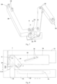
- FIGS. 1 through 12 linear hinge assemblies 200 will be described in more detail according to exemplary embodiments of the present disclosure.
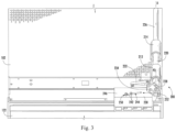
- FIGS. 1 and 3 illustrate a linear hinge assembly 200 in a closed position.
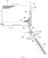
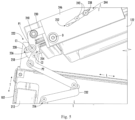
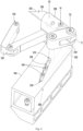
- FIG. 2 and 4 illustrate the same embodiment of linear hinge assembly 200 in an open position, while FIGS. 5 through 7 illustrate various portions of the same embodiment.
- FIG. 8 illustrates further exemplary embodiments of linear hinge assembly.
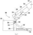
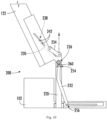
- FIGS. 9 and 10 illustrate other exemplary embodiments of linear hinge assembly.
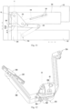
- FIG. 11 illustrates a portion of still other exemplary embodiments of the present disclosure.
- FIG. 12 illustrates a portion of yet other exemplary embodiments of the present disclosure.
- refrigerator appliance 100 may include bottom hinge assemblies that are substantially similar to the top linear hinge assemblies 200.
- linear hinge assembly 200 includes at least one bearing assembly 210 mounted to cabinet 102.
- bearing assembly 210 may be fastened or otherwise suitably fixed to cabinet 102. More specifically, as illustrated, bearing assembly 210 includes a front bearing 212 and a rear bearing 214 spaced apart along a translation axis A, which may correspond to the transverse direction T of appliance 100 (or another suitable direction).
- bearing assembly 210 is illustrated as including two linear slide bearings, it should be appreciated that bearing assembly 210 may include any suitable number and type of bearing configuration, such as ball bearings, low friction sleeves, or any other suitable slide or linear shaft bearings.
- Elongated shaft 220 is received within bearing assembly 210.
- elongated shaft 220 may slide along translation axis A on or within bearing assembly 210.
- elongated shaft 220 may extend and retract along the translation axis A on bearing assembly 210 as door 122 opens and closes.
- this translation provides clearance or minimizes interference between door 122 and adjacent cabinetry or other structures.
- Elongated shaft 220 may be formed from any suitably rigid material or materials.
- elongated shaft 220 may include a rigid translation body 226 (e.g., formed from cylindrical steel bar).
- a shaft bracket 228 may be provided at a distal end portion 222 of elongated shaft 220 (e.g., in fixed attachment to rigid translation body 226).
- one or more portions of elongated shaft 220 may be coated in any suitable coating, such as anodized aluminum or another suitable corrosion resistant coating.
- elongated shaft 220 extends along the translation axis A between a proximal end portion 224 and the distal end portion 222.
- distal end portion 222 may be cantilevered from bearing assembly 210 while proximal end portion 224 is generally positioned rearward from bearing assembly 210 (e.g., above cabinet 102).
- proximal end portion 224 is generally positioned rearward from bearing assembly 210 (e.g., above cabinet 102).
- multiple pivot axes may be defined to direct movement of door 122.
- distal end portion 222 of elongated shaft 220 is rotatably connected to door 122 (e.g., at shaft bracket 228).
- door 122 is rotatable about a door axis D offset from and translatable relative to elongated shaft 220.
- the door axis D may be perpendicular to the translation axis A.
- the door axis D may be vertically oriented (e.g., parallel to the vertical direction V), and the translation axis A may be horizontally oriented.
- door 122 is connected to cabinet 102 with linear hinge assembly 200 such that door 122 is translatable along the translation axis A relative to cabinet 102 and is also rotatable about the door axis D relative to cabinet 102.
- Door axis D itself may also be translatable (e.g., horizontally) relative to translation axis A as door 122 moves forward/rearward along translation axis A.
- linear hinge assembly 200 may translate door 122 along the translation axis A away from cabinet 102 as door 122 is rotated open about the door axis D.
- Translating door 122 away from cabinet 102 as door 122 rotates open notably assists with reducing interference between door 122 and adjacent cabinetry.
- translating door 122 away from cabinet 102 and relative to translation axis A as door 122 rotates open may also advantageously assist with limiting scraping of door 122 on a gasket (not shown) that extends between cabinet 102 and door 122 to seal the interior of cabinet 102.
- Elongated shaft 220 defines two or more shaft pivot axes coupled to separate linkages (e.g., via corresponding connection pins).
- elongated shaft 220 may define a first shaft pivot axis P1 at which a door linkage 230 is pivotally connected (e.g., via a corresponding connection pin extending along first shaft pivot axis P1) to couple door 122 to elongated shaft 220.
- elongated shaft 220 may define a second shaft pivot axis P2 at which a cabinet linkage 232 is pivotally connected (e.g., via a corresponding connection pin extending along second shaft pivot axis P2) to couple cabinet 102 to elongated shaft 220.
- first shaft pivot axis P1 and second shaft pivot axis P2 are perpendicular to the translation axis A. Moreover, first shaft pivot axis P1 and second shaft pivot axis P2 may be parallel to each other. As shown, first shaft pivot axis P1 and second shaft pivot axis P2 may be vertically oriented (e.g., parallel to the vertical direction V). In some embodiments, the first shaft pivot axis P1 is spaced apart from the second shaft pivot axis P2, as illustrated in FIGS. 1 through 7 , 9 , 10 , and 12 . Specifically, first shaft pivot axis P1 may be positioned apart from second shaft pivot axis P2 along the translation axis A.
- first shaft pivot axis P1 may be positioned forward from second shaft pivot axis P2 such that first shaft pivot axis P1 is closer to door 122 relative to the transverse direction T than second shaft pivot axis P2.
- first shaft pivot axis P1 may proximal to door 122 in comparison to second shaft pivot axis P2 along the translation axis A.
- first shaft pivot axis P1 and second shaft pivot axis P2 are coaxial or concentric with each other, as illustrated in FIGS. 8 and 11 .
- a third shaft pivot axis P3 is defined on elongated shaft 220.
- third shaft pivot axis P3 may be defined parallel to first shaft pivot axis P1 or second shaft pivot axis P2 (e.g., vertically oriented).
- third shaft pivot axis P3 is defined forward from first shaft pivot axis P1 or second shaft pivot axis P2 along the translation axis A (e.g., as the forwardmost shaft pivot axis).
- an offset link 234 may pivotally connect to elongated shaft 220 at a joint 240 defining third shaft pivot axis P3 (e.g., as or including a corresponding connection pin extending along third shaft pivot axis P3) to further couple elongated shaft 220 to door 122.
- offset link 234 also pivotally connects to door 122 at door axis D (e.g., via a corresponding connection pin extending along door axis D).
- offset link 234 may rotate about both door axis D and third shaft pivot axis P3.
- door linkage 230 generally includes one or more rigid arms or gears that join elongated shaft 220 to door 122 while being pivotable about first shaft pivot axis P1.
- door linkage 230 extends (e.g., horizontally) between a shaft end 236 proximal to distal end portion 222 of elongated shaft 220 and a guided end 238 disposed on door 122 (e.g., distal to distal end portion 222).
- shaft end 236 may be disposed at or adjacent to first shaft pivot axis P1.
- guided end 238 may be slidably disposed along a guide path 244 defined on the door 122.
- one or more slider pins 242 may be fixed to door linkage 230 while extending (e.g., vertically) through guide path 244, which may be defined on a support bracket 246 fixed to door 122, as illustrated in FIGS. 1 through 10 .
- guide path 244 may be defined on a support bracket 246 fixed to door 122, as illustrated in FIGS. 1 through 10 .
- a single rigid slider bar 248 may be fixed to door linkage 230 while being slidably mated to a rail 249 defining a guide path (e.g., as illustrated in FIG. 12 ), or another suitable sliding connection may be formed as would be understood.
- guide path 244 When door 122 is in the closed position, guide path 244 may extend, at least in part along the lateral direction L (e.g., at a nonorthogonal angle relative thereto). Thus, opposite path ends 250, 252 of guide path 244 may be laterally spaced apart when door 122 is in the closed position.
- An outer end 250 of guide path 244 may be distal to door axis D while an inner end 252 of guide path 244 is proximal to door axis D (e.g., along a horizontal direction, such as the lateral direction L).
- guided end 238 of door linkage 230 e.g., at least one slider pin 242
- guided end 238 (e.g., at least one slider pin 242) may be disposed at or proximal to the inner end 252.
- guide path 244 may be rotated outward and guided end 238 may slide along guide path 244 to move the guided end 238 away from the outer end 250 and closer to the inner end 252.
- guide path 244 may be rotated inward and guided end 238 may slide along guide path 244 to move the guided end 238 away from the inner end 252 and closer to the outer end 250.
- door linkage 230 is arranged such that at least a portion of the rotational force of door linkage 230 about first shaft pivot axis P1 is directed to cabinet linkage 232.
- shaft end 236 of door linkage 230 may be in mechanical communication with an extendable end 254 of cabinet linkage 232.
- an intermediate link 258 may be provided, as shown in FIGS. 1 through 7 .
- intermediate link 258 is movably mounted on elongated shaft 220 at a location that is between first shaft pivot axis P1 and second shaft pivot axis P2 (e.g., between P1 and P2 along or relative to translation axis A).
- intermediate link 258 may extend between a first cam axis C1 and a second cam axis C2, both of which may be parallel to first shaft pivot axis P1 and second shaft pivot axis P2.
- intermediate link 258 may be coupled to door linkage 230 at first cam axis C1 and to cabinet linkage 232 at second cam axis C2 (e.g., via discrete corresponding connection pins).
- First cam axis C1 of intermediate link 258 may specifically couple to the shaft end 236 of door linkage 230 while second cam axis C2 couples to the extendable end 254 of cabinet linkage 232.
- an intermediate gear set 260 may be provided, as shown in various embodiments between FIGS. 8 through 12 .
- intermediate gear set 260 may be enmeshed in mechanical communication between the door linkage 230 at the first shaft pivot axis P1 and the cabinet linkage 232 at the second shaft pivot axis P2.
- mated gear teeth may be provided on the shaft end 236 of door linkage 230 and the extendable end 254 of cabinet linkage 232.
- two or more scissor gear arms may be provided with one end (e.g., arm) coupled to the coaxial first and second shaft pivot axes P1, P2 and another arm coupled to door 122 (e.g., at a separate gear axis).
- Cabinet linkage 232 generally includes one or more rigid arms or gears that further join elongated shaft 220 to cabinet 102. During use, cabinet linkage 232 may specifically help transfer rotation of door 122 to linear translation of elongated shaft 220. As shown, cabinet linkage 232 may extend (e.g., horizontally) between the extendable end 254 coupled to distal end portion 222 of elongated shaft 220 and the rearward end 256 disposed on cabinet 102 (e.g., apart from distal end portion 222). For instance, extendable end 254 may be disposed at or adjacent to second shaft pivot axis P2. By contrast, rearward end 256 may be slidably or pivotally disposed on cabinet 102. In some such embodiments, such as those illustrated in FIGS.
- cabinet linkage 232 includes multiple rigid arms pivotally coupled between extendable end 254 and rearward end 256.
- Rotation at second shaft pivot axis P2 (e.g., motivated at least in part by rotation of door 122) may thus motivate expansion or contract of the rigid arms depending on whether the door 122 is being opened or closed, respectively.
- a single rigid bar is provided between extendable end 254 and rearward end 256, which may slide horizontally (e.g., parallel to the lateral direction L) along a cabinet 102 guide while rotating to permit translation of extendable end 254 relative to cabinet 102.
- cabinet linkage 232 may thus force elongated shaft 220 forward with extendable end 254 as rearward end 256 pivots or slides on cabinet 102.
- cabinet linkage 232 may force elongated shaft 220 rearward with extendable end 254 as rearward end 256 pivots or slides in the opposite direction from the opening.
Landscapes
- Engineering & Computer Science (AREA)
- Mechanical Engineering (AREA)
- Chemical & Material Sciences (AREA)
- Combustion & Propulsion (AREA)
- Physics & Mathematics (AREA)
- Thermal Sciences (AREA)
- General Engineering & Computer Science (AREA)
- Refrigerator Housings (AREA)
- Hinges (AREA)
Abstract
Description
- The present disclosure relates generally to refrigerator appliances, and more particularly, to linear hinges for refrigerator appliances.
- Refrigerator appliances generally include a cabinet that defines a chilled chamber for receipt of food articles for storage. In addition, refrigerator appliances include one or more doors rotatably hinged to the cabinet to permit selective access to food items stored in chilled chamber(s). The refrigerator appliances can also include various storage components mounted within the chilled chamber and designed to facilitate storage of food items therein. Such storage components can include racks, bins, shelves, or drawers that receive food items and assist with organizing and arranging of such food items within the chilled chamber.
- Refrigerator appliances are commonly positioned within a recess in a row of cabinets mounted to a wall in a kitchen. In order to improve the appearance of the refrigerator appliance and minimize protrusion into kitchen walkways, certain refrigerator appliances are designed to be flush mount, where the front of the appliance door sits substantially flush with a front of the cabinets when the doors are closed. In addition, such refrigerators may be designed for receiving a cabinet panel, such that the front appearance of the refrigerator appliance matches the appearance of the cabinetry. However, conventional refrigerator appliances include doors that pivot around a single pivoting axis or hinge, which may cause the door or the panel mounted thereon to rub or conflict with adjacent cabinetry. In addition, refrigerator doors may frequently experience gasket rub or wear as the door is opened and closed repeatedly.
- Accordingly, a refrigerator appliance with an improved hinge assembly would be useful. More particularly, a hinge assembly that reduces the likelihood of contact between the refrigerator door and adjacent cabinetry would be particularly beneficial.
- Aspects and advantages of the invention will be set forth in part in the following description, or may be obvious from the description, or may be learned through practice of the invention.
- In one exemplary aspect of the present disclosure, a domestic appliance is provided. The domestic appliance may include a cabinet, a door, and a linear hinge coupling the door to the cabinet. The linear hinge may include a bearing assembly, an elongated shaft, a door linkage, and a cabinet linkage. The bearing assembly may be mounted to the cabinet. The elongated shaft may be received within the bearing assembly such that the elongated shaft is slidable along a translation axis on the bearing assembly. The elongated shaft may define a first shaft pivot axis perpendicular to the translation axis and a second shaft pivot axis parallel to the first shaft pivot axis. The door linkage may couple the door to the elongated shaft. The door linkage may be pivotally connected to the elongated shaft at the first shaft pivot axis. The cabinet linkage may couple the cabinet to the elongated shaft. The cabinet linkage may be pivotally connected to the elongated shaft at the second shaft pivot axis.
- In another exemplary aspect of the present disclosure, a refrigerator appliance is provided. The refrigerator appliance may include a cabinet, a door, and a linear hinge coupling the door to the cabinet. The linear hinge may include a bearing assembly, an elongated shaft, a door linkage, a cabinet linkage, and an offset link. The bearing assembly may be mounted to the cabinet. The elongated shaft may be received within the bearing assembly such that the elongated shaft is slidable along a translation axis on the bearing assembly. The elongated shaft may define a first shaft pivot axis, a second shaft pivot axis, and a third shaft pivot axis. The first shaft pivot axis may be perpendicular to the translation axis. The second and third shaft pivot axes may be parallel to the first shaft pivot axis. The door linkage may couple the door to the elongated shaft. The door linkage may be pivotally connected to the elongated shaft at the first shaft pivot axis. The cabinet linkage may couple the cabinet to the elongated shaft. The cabinet linkage may be pivotally connected to the elongated shaft at the second shaft pivot axis. The offset link may be pivotally connected to the elongated shaft at the third shaft pivot axis and to the door at a door pivot axis.
- These and other features, aspects and advantages of the present invention will become better understood with reference to the following description and appended claims. The accompanying drawings, which are incorporated in and constitute a part of this specification, illustrate embodiments of the invention and, together with the description, serve to explain the principles of the invention.
- A full and enabling disclosure of the present invention, including the best mode thereof, directed to one of ordinary skill in the art, is set forth in the specification, which makes reference to the appended figures.
-
FIG. 1 provides a top perspective view of a refrigerator appliance according to exemplary embodiments of the present disclosure. -
FIG. 2 provides a top perspective view of the exemplary refrigerator appliance ofFIG. 1 , wherein the door is an open position. -
FIG. 3 provides a magnified perspective view of a portion of the linear hinge assembly of the exemplary refrigerator appliance ofFIG. 1 . -
FIG. 4 provides a top plan view of a portion of the exemplary refrigerator appliance ofFIG. 1 , wherein the door is an open position -
FIG. 5 provides a top perspective view of a portion of the linear hinge assembly of the exemplary refrigerator appliance ofFIG. 1 . -
FIG. 6 provides a front perspective view of a portion of the linear hinge assembly of the exemplary refrigerator appliance ofFIG. 1 . -
FIG. 7 provides a front perspective view of a portion of the linear hinge assembly of the exemplary refrigerator appliance ofFIG. 1 . -
FIG. 8 provides a top plan view of a linear hinge assembly of a refrigerator appliance according to exemplary embodiments of the present disclosure, wherein a door is in a closed position. -
FIG. 9 provides a top plan view of a linear hinge assembly of a refrigerator appliance according to exemplary embodiments of the present disclosure, wherein the door is in an intermediate position. -
FIG. 10 provides a top plan view of the exemplary linear hinge ofFIG. 9 , wherein the door is in an open position. -
FIG. 11 provides a top plan view of a linear hinge assembly of a refrigerator appliance according to exemplary embodiments of the present disclosure, wherein a door is in a closed position. -
FIG. 12 provides a side perspective view of a portion of a linear hinge assembly of a refrigerator appliance according to exemplary embodiments of the present disclosure, wherein a door is in a closed position. - Reference now will be made in detail to embodiments of the invention, one or more examples of which are illustrated in the drawings. Each example is provided by way of explanation of the invention, not limitation of the invention. In fact, it will be apparent to those skilled in the art that various modifications and variations can be made in the present invention without departing from the scope of the invention. For instance, features illustrated or described as part of one embodiment can be used with another embodiment to yield a still further embodiment. Thus, it is intended that the present invention covers such modifications and variations as come within the scope of the appended claims and their equivalents.
- Reference will now be made in detail to present embodiments of the invention, one or more examples of which are illustrated in the accompanying drawings. The detailed description uses numerical and letter designations to refer to features in the drawings. Like or similar designations in the drawings and description have been used to refer to like or similar parts of the invention. As used herein, the term "or" is generally intended to be inclusive (i.e., "A or B" is intended to mean "A or B or both"). The terms "first," "second," and "third" may be used interchangeably to distinguish one component from another and are not intended to signify location or importance of the individual components.
-
FIG. 1 is a perspective view of anappliance 100, such as a refrigerator appliance, according to exemplary embodiments of the present disclosure. As may be seen inFIG. 1 ,appliance 100 includes a housing orcabinet 102 that extends between a top 104 and a bottom 106 along a vertical direction V, between afirst side 108 and asecond side 110 along a lateral direction L, and between afront side 112 and arear side 114 along a transverse direction T. Each of the vertical direction V, lateral direction L, and transverse direction T are mutually perpendicular to one another. -
Cabinet 102 generally defines one or morechilled chambers 120 for receipt of food items for storage.Cabinet 102 may be insulated andrefrigerator appliance 100 may further include a sealed system (not shown) that is operable to cool chilledchamber 120 and food items stored therein. Althoughrefrigerator appliance 100 is illustrated as a single compartment refrigerator, it should be appreciated that aspects of the present disclosure may be applied to other types of refrigerator appliances, such as bottom mount, top mount, and side-by-side refrigerator appliances. Moreover, aspects of the present disclosure may be used for any other suitable appliance that includes a rotating door. For example, aspects of the present disclosure may be used in or with French door oven appliances, dishwasher appliances, etc. to mount a door to a cabinet, such as a base, a tub, etc. - Referring still to
FIG. 1 , adoor 122 is coupled tocabinet 102 with one or more linear hinge assemblies 200 (e.g., located at a top and a bottom of door 122). A user may rotatedoor 122 open to access and interior of cabinet 102 (e.g., chilled chamber 120), and the user may rotatedoor 122 closed to seal the interior ofcabinet 102.Door 122 may also include ahandle 124 that a user may pull when opening and closingdoor 122.Linear hinge assemblies 200 will be described herein in more detail according to exemplary embodiments of the present disclosure. In general, linear hinges are used to allow doors to translate away from adjacent cabinetry or appliances in addition to rotating open and closed. By translating in addition to rotating, interference between the doors and the adjacent cabinetry or the appliance itself can be avoided. - Referring generally to
FIGS. 1 through 12 ,linear hinge assemblies 200 will be described in more detail according to exemplary embodiments of the present disclosure. Specifically,FIGS. 1 and3 illustrate alinear hinge assembly 200 in a closed position.FIG. 2 and4 illustrate the same embodiment oflinear hinge assembly 200 in an open position, whileFIGS. 5 through 7 illustrate various portions of the same embodiment.FIG. 8 illustrates further exemplary embodiments of linear hinge assembly.FIGS. 9 and10 illustrate other exemplary embodiments of linear hinge assembly.FIG. 11 illustrates a portion of still other exemplary embodiments of the present disclosure.FIG. 12 illustrates a portion of yet other exemplary embodiments of the present disclosure. As noted above, due to the similarity between the embodiments oflinear hinge assemblies 200 described herein, like reference numerals will be used to refer to the same of substantially similar features between embodiments. Although only toplinear hinge assemblies 200 are illustrated and described in detail, it should be appreciated thatrefrigerator appliance 100 may include bottom hinge assemblies that are substantially similar to the toplinear hinge assemblies 200. - As illustrated,
linear hinge assembly 200 includes at least onebearing assembly 210 mounted tocabinet 102. As an example, bearingassembly 210 may be fastened or otherwise suitably fixed tocabinet 102. More specifically, as illustrated, bearingassembly 210 includes afront bearing 212 and arear bearing 214 spaced apart along a translation axis A, which may correspond to the transverse direction T of appliance 100 (or another suitable direction). Although bearingassembly 210 is illustrated as including two linear slide bearings, it should be appreciated that bearingassembly 210 may include any suitable number and type of bearing configuration, such as ball bearings, low friction sleeves, or any other suitable slide or linear shaft bearings. - An
elongated shaft 220 is received within bearingassembly 210. In particular,elongated shaft 220 may slide along translation axis A on or within bearingassembly 210. Thus, for example,elongated shaft 220 may extend and retract along the translation axis A on bearingassembly 210 asdoor 122 opens and closes. Notably, as described below, this translation provides clearance or minimizes interference betweendoor 122 and adjacent cabinetry or other structures.Elongated shaft 220 may be formed from any suitably rigid material or materials. For instance,elongated shaft 220 may include a rigid translation body 226 (e.g., formed from cylindrical steel bar). Additionally or alternatively, ashaft bracket 228 may be provided at adistal end portion 222 of elongated shaft 220 (e.g., in fixed attachment to rigid translation body 226). Optionally, one or more portions ofelongated shaft 220 may be coated in any suitable coating, such as anodized aluminum or another suitable corrosion resistant coating. - As shown,
elongated shaft 220 extends along the translation axis A between aproximal end portion 224 and thedistal end portion 222. When assembled,distal end portion 222 may be cantilevered from bearingassembly 210 whileproximal end portion 224 is generally positioned rearward from bearing assembly 210 (e.g., above cabinet 102). At or adjacent to thedistal end portion 222, multiple pivot axes may be defined to direct movement ofdoor 122. - Generally,
distal end portion 222 ofelongated shaft 220 is rotatably connected to door 122 (e.g., at shaft bracket 228). In particular,door 122 is rotatable about a door axis D offset from and translatable relative toelongated shaft 220. The door axis D may be perpendicular to the translation axis A. For example, the door axis D may be vertically oriented (e.g., parallel to the vertical direction V), and the translation axis A may be horizontally oriented. - As shown,
door 122 is connected tocabinet 102 withlinear hinge assembly 200 such thatdoor 122 is translatable along the translation axis A relative tocabinet 102 and is also rotatable about the door axis D relative tocabinet 102. Door axis D itself may also be translatable (e.g., horizontally) relative to translation axis A asdoor 122 moves forward/rearward along translation axis A. Thus, for instance, whendoor 122 includes an outer panel that is flush mounted with adjacent cabinetry,linear hinge assembly 200 may translatedoor 122 along the translation axis A away fromcabinet 102 asdoor 122 is rotated open about the door axisD. Translating door 122 away fromcabinet 102 asdoor 122 rotates open notably assists with reducing interference betweendoor 122 and adjacent cabinetry. In addition, translatingdoor 122 away fromcabinet 102 and relative to translation axis A asdoor 122 rotates open may also advantageously assist with limiting scraping ofdoor 122 on a gasket (not shown) that extends betweencabinet 102 anddoor 122 to seal the interior ofcabinet 102. - As noted above, multiple (e.g., parallel) pivot axes may be defined at or adjacent to
distal end portion 222 ofelongated shaft 220.Elongated shaft 220, in particular, defines two or more shaft pivot axes coupled to separate linkages (e.g., via corresponding connection pins). For instance,elongated shaft 220 may define a first shaft pivot axis P1 at which adoor linkage 230 is pivotally connected (e.g., via a corresponding connection pin extending along first shaft pivot axis P1) tocouple door 122 toelongated shaft 220. Additionally,elongated shaft 220 may define a second shaft pivot axis P2 at which acabinet linkage 232 is pivotally connected (e.g., via a corresponding connection pin extending along second shaft pivot axis P2) tocouple cabinet 102 toelongated shaft 220. - Generally, first shaft pivot axis P1 and second shaft pivot axis P2 are perpendicular to the translation axis A. Moreover, first shaft pivot axis P1 and second shaft pivot axis P2 may be parallel to each other. As shown, first shaft pivot axis P1 and second shaft pivot axis P2 may be vertically oriented (e.g., parallel to the vertical direction V). In some embodiments, the first shaft pivot axis P1 is spaced apart from the second shaft pivot axis P2, as illustrated in
FIGS. 1 through 7 ,9 ,10 , and12 . Specifically, first shaft pivot axis P1 may be positioned apart from second shaft pivot axis P2 along the translation axis A. For instance, first shaft pivot axis P1 may be positioned forward from second shaft pivot axis P2 such that first shaft pivot axis P1 is closer to door 122 relative to the transverse direction T than second shaft pivot axis P2. In other words, first shaft pivot axis P1 may proximal todoor 122 in comparison to second shaft pivot axis P2 along the translation axis A. In alternative embodiments, first shaft pivot axis P1 and second shaft pivot axis P2 are coaxial or concentric with each other, as illustrated inFIGS. 8 and11 . - In certain embodiments, a third shaft pivot axis P3 is defined on
elongated shaft 220. For instance, third shaft pivot axis P3 may be defined parallel to first shaft pivot axis P1 or second shaft pivot axis P2 (e.g., vertically oriented). In some embodiments, third shaft pivot axis P3 is defined forward from first shaft pivot axis P1 or second shaft pivot axis P2 along the translation axis A (e.g., as the forwardmost shaft pivot axis). As shown, an offset link 234 (e.g., rigid linkage bar) may pivotally connect toelongated shaft 220 at a joint 240 defining third shaft pivot axis P3 (e.g., as or including a corresponding connection pin extending along third shaft pivot axis P3) to further couple elongatedshaft 220 todoor 122. In some such embodiments, offsetlink 234 also pivotally connects to door 122 at door axis D (e.g., via a corresponding connection pin extending along door axis D). Thus, asdoor 122 rotates, offsetlink 234 may rotate about both door axis D and third shaft pivot axis P3. - As shown,
door linkage 230 generally includes one or more rigid arms or gears that joinelongated shaft 220 todoor 122 while being pivotable about first shaft pivot axis P1. In some embodiments,door linkage 230 extends (e.g., horizontally) between ashaft end 236 proximal todistal end portion 222 ofelongated shaft 220 and a guidedend 238 disposed on door 122 (e.g., distal to distal end portion 222). For instance,shaft end 236 may be disposed at or adjacent to first shaft pivot axis P1. By contrast, guidedend 238 may be slidably disposed along aguide path 244 defined on thedoor 122. - Optionally, one or more slider pins 242 (e.g., a pair of slider pins 242) may be fixed to
door linkage 230 while extending (e.g., vertically) throughguide path 244, which may be defined on asupport bracket 246 fixed todoor 122, as illustrated inFIGS. 1 through 10 . Alternatively, however, a singlerigid slider bar 248 may be fixed todoor linkage 230 while being slidably mated to arail 249 defining a guide path (e.g., as illustrated inFIG. 12 ), or another suitable sliding connection may be formed as would be understood. - When
door 122 is in the closed position, guidepath 244 may extend, at least in part along the lateral direction L (e.g., at a nonorthogonal angle relative thereto). Thus, opposite path ends 250, 252 ofguide path 244 may be laterally spaced apart whendoor 122 is in the closed position. Anouter end 250 ofguide path 244 may be distal to door axis D while aninner end 252 ofguide path 244 is proximal to door axis D (e.g., along a horizontal direction, such as the lateral direction L). In the closed position, guidedend 238 of door linkage 230 (e.g., at least one slider pin 242) may be disposed at or proximal to theouter end 250. By contrast in the open position, guided end 238 (e.g., at least one slider pin 242) may be disposed at or proximal to theinner end 252. Thus, asdoor 122 is rotated open, guidepath 244 may be rotated outward and guidedend 238 may slide alongguide path 244 to move the guidedend 238 away from theouter end 250 and closer to theinner end 252. Similarly, asdoor 122 is rotated closed, guidepath 244 may be rotated inward and guidedend 238 may slide alongguide path 244 to move the guidedend 238 away from theinner end 252 and closer to theouter end 250. - In certain embodiments,
door linkage 230 is arranged such that at least a portion of the rotational force ofdoor linkage 230 about first shaft pivot axis P1 is directed tocabinet linkage 232. Specifically,shaft end 236 ofdoor linkage 230 may be in mechanical communication with anextendable end 254 ofcabinet linkage 232. - As an example, an
intermediate link 258 may be provided, as shown inFIGS. 1 through 7 . In some such embodiments,intermediate link 258 is movably mounted onelongated shaft 220 at a location that is between first shaft pivot axis P1 and second shaft pivot axis P2 (e.g., between P1 and P2 along or relative to translation axis A). As shown,intermediate link 258 may extend between a first cam axis C1 and a second cam axis C2, both of which may be parallel to first shaft pivot axis P1 and second shaft pivot axis P2. Moreover,intermediate link 258 may be coupled todoor linkage 230 at first cam axis C1 and tocabinet linkage 232 at second cam axis C2 (e.g., via discrete corresponding connection pins). First cam axis C1 ofintermediate link 258 may specifically couple to theshaft end 236 ofdoor linkage 230 while second cam axis C2 couples to theextendable end 254 ofcabinet linkage 232. - As another example, an intermediate gear set 260 may be provided, as shown in various embodiments between
FIGS. 8 through 12 . Specifically, intermediate gear set 260 may be enmeshed in mechanical communication between thedoor linkage 230 at the first shaft pivot axis P1 and thecabinet linkage 232 at the second shaft pivot axis P2. For instance, as shown inFIGS. 9 ,10 , and12 , mated gear teeth may be provided on theshaft end 236 ofdoor linkage 230 and theextendable end 254 ofcabinet linkage 232. Additionally or alternatively, two or more scissor gear arms may be provided with one end (e.g., arm) coupled to the coaxial first and second shaft pivot axes P1, P2 and another arm coupled to door 122 (e.g., at a separate gear axis). -
Cabinet linkage 232 generally includes one or more rigid arms or gears that further joinelongated shaft 220 tocabinet 102. During use,cabinet linkage 232 may specifically help transfer rotation ofdoor 122 to linear translation ofelongated shaft 220. As shown,cabinet linkage 232 may extend (e.g., horizontally) between theextendable end 254 coupled todistal end portion 222 ofelongated shaft 220 and therearward end 256 disposed on cabinet 102 (e.g., apart from distal end portion 222). For instance,extendable end 254 may be disposed at or adjacent to second shaft pivot axis P2. By contrast, rearward end 256 may be slidably or pivotally disposed oncabinet 102. In some such embodiments, such as those illustrated inFIGS. 1 through 7 and11 ,cabinet linkage 232 includes multiple rigid arms pivotally coupled betweenextendable end 254 andrearward end 256. Rotation at second shaft pivot axis P2 (e.g., motivated at least in part by rotation of door 122) may thus motivate expansion or contract of the rigid arms depending on whether thedoor 122 is being opened or closed, respectively. In other embodiments, such as those illustrated inFIGS. 8 through 10 and12 a single rigid bar is provided betweenextendable end 254 andrearward end 256, which may slide horizontally (e.g., parallel to the lateral direction L) along acabinet 102 guide while rotating to permit translation ofextendable end 254 relative tocabinet 102. - As
door 122 is rotated open,cabinet linkage 232 may thus forceelongated shaft 220 forward withextendable end 254 asrearward end 256 pivots or slides oncabinet 102. Similarly, asdoor 122 is rotated closed,cabinet linkage 232 may forceelongated shaft 220 rearward withextendable end 254 asrearward end 256 pivots or slides in the opposite direction from the opening. - This written description uses examples to disclose the invention, including the best mode, and also to enable any person skilled in the art to practice the invention, including making and using any devices or systems and performing any incorporated methods. The patentable scope of the invention is defined by the claims, and may include other examples that occur to those skilled in the art. Such other examples are intended to be within the scope of the claims if they include structural elements that do not differ from the literal language of the claims, or if they include equivalent structural elements with insubstantial differences from the literal languages of the claims.
Claims (19)
- A domestic appliance comprising:a cabinet;a door; anda linear hinge coupling the door to the cabinet, the linear hinge comprisinga bearing assembly mounted to the cabinet,an elongated shaft received within the bearing assembly such that the elongated shaft is slidable along a translation axis on the bearing assembly, the elongated shaft defining a first shaft pivot axis perpendicular to the translation axis and a second shaft pivot axis parallel to the first shaft pivot axis,a door linkage coupling the door to the elongated shaft, the door linkage being pivotally connected to the elongated shaft at the first shaft pivot axis, anda cabinet linkage coupling the cabinet to the elongated shaft, the cabinet linkage being pivotally connected to the elongated shaft at the second shaft pivot axis.
- The domestic appliance of claim 1, wherein the first shaft pivot axis is spaced apart from the second pivot axis along the translation axis,
- The domestic appliance of claim 1, wherein the first shaft pivot axis is defined forward from the second shaft pivot axis along the translation axis.
- The domestic appliance of claim 1, wherein the linear hinge further comprises
an offset link pivotally connected to the elongated shaft at a third shaft pivot axis and to the door at a door pivot axis. - The domestic appliance of claim 4, wherein the third shaft pivot axis is defined forward from the first shaft pivot axis on the elongated shaft.
- The domestic appliance of claim 1, wherein the door linkage is fixedly connected to the door at a door joint.
- The domestic appliance of claim 1, wherein the door linkage comprises a guided end slidably disposed along a guide path defined on the door.
- The domestic appliance of claim 7, wherein the door linkage is fixedly connected to the door at a door joint, and wherein the door joint is disposed between the guided end and the first shaft pivot axis along the door linkage.
- The domestic appliance of claim 1, wherein the linear hinge further comprises
an intermediate link movably mounted on the elongated shaft between the first shaft pivot axis and the second shaft pivot axis, the intermediate link extending between a first cam axis and a second cam axis, the intermediate link being coupled to the door linkage at the first cam axis and coupled to the cabinet linkage at the second cam axis. - The domestic appliance of claim 1, wherein the linear hinge further comprises
an intermediate gear set enmeshed in mechanical communication between the door linkage at the first shaft pivot axis and the cabinet linkage at the second shaft pivot axis. - A refrigerator appliance comprising:a cabinet;a door; anda linear hinge coupling the door to the cabinet, the linear hinge comprisinga bearing assembly mounted to the cabinet,an elongated shaft received within the bearing assembly such that the elongated shaft is slidable along a translation axis on the bearing assembly, the elongated shaft defining a first shaft pivot axis, a second shaft pivot axis, and a third shaft pivot axis, the first shaft pivot axis being perpendicular to the translation axis, the second and third shaft pivot axes being parallel to the first shaft pivot axis,a door linkage coupling the door to the elongated shaft, the door linkage being pivotally connected to the elongated shaft at the first shaft pivot axis,a cabinet linkage coupling the cabinet to the elongated shaft, the cabinet linkage being pivotally connected to the elongated shaft at the second shaft pivot axis, andan offset link pivotally connected to the elongated shaft at the third shaft pivot axis and to the door at a door pivot axis.
- The refrigerator appliance of claim 11, wherein the first shaft pivot axis is spaced apart from the second pivot axis along the translation axis,
- The refrigerator appliance of claim 11, wherein the first shaft pivot axis is defined forward from the second shaft pivot axis along the translation axis.
- The refrigerator appliance of claim 11, wherein the third shaft pivot axis is defined forward from the first shaft pivot axis on the elongated shaft.
- The refrigerator appliance of claim 11, wherein the door linkage is fixedly connected to the door at a door joint.
- The refrigerator appliance of claim 11, wherein the door linkage comprises a guided end slidably disposed along a guide path defined on the door.
- The refrigerator appliance of claim 16, wherein the door linkage is fixedly connected to the door at a door j oint, and wherein the door joint is disposed between the guided end and the first shaft pivot axis along the door linkage.
- The refrigerator appliance of claim 11, wherein the linear hinge further comprises
an intermediate link movably mounted on the elongated shaft between the first shaft pivot axis and the second shaft pivot axis, the intermediate link extending between a first cam axis and a second cam axis, the intermediate link being coupled to the door linkage at the first cam axis and coupled to the cabinet linkage at the second cam axis. - The refrigerator appliance of claim 11, wherein the linear hinge further comprises
an intermediate gear set enmeshed in mechanical communication between the door linkage at the first shaft pivot axis and the cabinet linkage at the second shaft pivot axis.
Applications Claiming Priority (2)
| Application Number | Priority Date | Filing Date | Title |
|---|---|---|---|
| US17/113,319 US11725443B2 (en) | 2020-12-07 | 2020-12-07 | Linear hinge assembly for an appliance |
| PCT/CN2021/134837 WO2022121752A1 (en) | 2020-12-07 | 2021-12-01 | Linear hinge assembly for appliance |
Publications (3)
| Publication Number | Publication Date |
|---|---|
| EP4257900A1 true EP4257900A1 (en) | 2023-10-11 |
| EP4257900A4 EP4257900A4 (en) | 2024-05-08 |
| EP4257900B1 EP4257900B1 (en) | 2025-03-26 |
Family
ID=81849840
Family Applications (1)
| Application Number | Title | Priority Date | Filing Date |
|---|---|---|---|
| EP21902459.3A Active EP4257900B1 (en) | 2020-12-07 | 2021-12-01 | Linear hinge assembly for appliance |
Country Status (5)
| Country | Link |
|---|---|
| US (1) | US11725443B2 (en) |
| EP (1) | EP4257900B1 (en) |
| CN (1) | CN116670435B (en) |
| AU (1) | AU2021394320B2 (en) |
| WO (1) | WO2022121752A1 (en) |
Families Citing this family (2)
| Publication number | Priority date | Publication date | Assignee | Title |
|---|---|---|---|---|
| CN114688817B (en) * | 2020-12-31 | 2023-03-17 | 青岛海尔电冰箱有限公司 | Automatic door opening and closing device for refrigerator and refrigerator with same |
| DE102022106566A1 (en) * | 2022-03-21 | 2023-09-21 | Grass Gmbh | Hinge arrangement and furniture or household appliance |
Family Cites Families (34)
| Publication number | Priority date | Publication date | Assignee | Title |
|---|---|---|---|---|
| US4827569A (en) * | 1986-08-01 | 1989-05-09 | Mertes Paul M | Flush mounted, fully concealed cabinet hinges |
| US5040857A (en) * | 1990-05-21 | 1991-08-20 | Maytag Corporation | Door hinge assembly for a refrigerator cabinet |
| DE29707359U1 (en) * | 1997-04-23 | 1998-08-27 | Ferco International Ferrures et Serrures de Bâtiment S.A., Reding | Window or door with rotating sash as well as fittings and hinges for storing the rotating sash |
| US6845545B2 (en) * | 2002-09-04 | 2005-01-25 | Samsung Electronics Co., Ltd. | Apparatus to close a door of a refrigerator |
| KR100495629B1 (en) * | 2003-07-31 | 2005-06-16 | 삼성전자주식회사 | Refrigerator |
| CN2773274Y (en) * | 2005-02-05 | 2006-04-19 | 同济大学科学技术开发公司 | Synchronously sliding special hidden hinge with high strength |
| KR20080002821A (en) * | 2005-04-26 | 2008-01-04 | 수스파 홀딩 게엠베하 | Hinge device |
| US20070234518A1 (en) * | 2006-04-07 | 2007-10-11 | Shin Zu Shing Co., Ltd. | Linear hinge |
| US7748080B2 (en) * | 2007-01-17 | 2010-07-06 | Sub-Zero, Inc. | Hinge and closure device for refrigerator |
| KR100872226B1 (en) | 2007-04-20 | 2008-12-05 | 엘지전자 주식회사 | Refrigerator |
| DE102008005463A1 (en) * | 2008-01-21 | 2009-07-23 | Huwil-Werke Gmbh Möbelschloss- Und Beschlagfabriken | Retaining element for adjusting a lid of a piece of furniture |
| US8443489B2 (en) * | 2009-02-05 | 2013-05-21 | Mansfield Assemblies Co. | Appliance hinge counterbalance assembly |
| KR101157801B1 (en) * | 2010-09-13 | 2012-06-25 | 풍원공업 주식회사 | door hinge |
| DE102010047774B4 (en) * | 2010-10-08 | 2018-07-19 | Frinova Gmbh | door hinge |
| KR101255516B1 (en) * | 2011-11-16 | 2013-04-23 | 풍원공업 주식회사 | Door hinge |
| US8572808B2 (en) * | 2012-02-23 | 2013-11-05 | Sub-Zero, Inc. | Controlled closure system for a hinge |
| KR101972539B1 (en) | 2012-04-23 | 2019-08-26 | 주식회사 위니아대우 | Door hinge for refrigerator |
| ITBO20120531A1 (en) | 2012-09-28 | 2014-03-29 | Nuova Star Spa | HINGE FOR A LEAF OF A HOUSEHOLD APPLIANCE |
| KR102100252B1 (en) * | 2015-01-05 | 2020-04-13 | 삼성전자주식회사 | Refrigerator |
| ITUB20152915A1 (en) * | 2015-08-05 | 2017-02-05 | C M I Cerniere Mecc Industriali Srl | HINGE DEVICE WITH LONG TRANSLATION OF A FRONT PANEL |
| CN105442964B (en) * | 2015-12-28 | 2017-03-01 | 泉州装备制造研究所 | A butterfly door hinge |
| EP3526431A4 (en) * | 2016-10-17 | 2020-06-10 | Whirlpool Corporation | HINGE ASSEMBLY |
| KR102651195B1 (en) * | 2016-11-30 | 2024-03-27 | 삼성전자주식회사 | Refrigerator |
| KR102253487B1 (en) * | 2017-01-03 | 2021-05-18 | 삼성전자주식회사 | A built-in refrigerator including a wire cover unit |
| IT201700049646A1 (en) * | 2017-05-08 | 2018-11-08 | Faringosi Hinges Srl | Hinge for household appliance |
| US11261631B2 (en) * | 2017-05-11 | 2022-03-01 | Samet Kalip Ve Maden Esya San. Ve Tic. A.S. | Hinge having pinch protection and method for displacing securing parts of a hinge |
| EP3476715A1 (en) * | 2017-10-26 | 2019-05-01 | Pa.Cotte Sa | Mechanism for opening/closing a door leaf relative to a frame |
| CN108253711B (en) * | 2017-12-12 | 2020-09-29 | 青岛海尔股份有限公司 | Refrigerator with a door |
| DE102018100674B4 (en) * | 2018-01-12 | 2020-03-05 | Hettich-Oni Gmbh & Co. Kg | Furniture plate with a hinge and furniture with such a furniture plate |
| US11078701B2 (en) * | 2019-01-04 | 2021-08-03 | Haier Us Appliance Solutions, Inc. | Linear hinge for an appliance |
| US10822852B1 (en) * | 2019-07-19 | 2020-11-03 | Haier Us Appliance Solutions, Inc. | Linear hinge assembly for an appliance |
| US10725505B1 (en) * | 2019-09-26 | 2020-07-28 | Dell Products L.P. | Synchronized expandable hinge assembly |
| CN211666491U (en) * | 2019-11-01 | 2020-10-13 | 东莞市鼎太电器有限公司 | Manual-automatic integrated electric oven door hinge |
| KR20220022225A (en) * | 2020-08-18 | 2022-02-25 | 엘지전자 주식회사 | Refrigerator |
-
2020
- 2020-12-07 US US17/113,319 patent/US11725443B2/en active Active
-
2021
- 2021-12-01 AU AU2021394320A patent/AU2021394320B2/en active Active
- 2021-12-01 EP EP21902459.3A patent/EP4257900B1/en active Active
- 2021-12-01 WO PCT/CN2021/134837 patent/WO2022121752A1/en not_active Ceased
- 2021-12-01 CN CN202180081699.7A patent/CN116670435B/en active Active
Also Published As
| Publication number | Publication date |
|---|---|
| AU2021394320A1 (en) | 2023-06-29 |
| AU2021394320B2 (en) | 2024-07-25 |
| EP4257900A4 (en) | 2024-05-08 |
| US20220178187A1 (en) | 2022-06-09 |
| CN116670435A (en) | 2023-08-29 |
| AU2021394320A9 (en) | 2025-01-16 |
| US11725443B2 (en) | 2023-08-15 |
| WO2022121752A1 (en) | 2022-06-16 |
| EP4257900B1 (en) | 2025-03-26 |
| CN116670435B (en) | 2026-02-03 |
Similar Documents
| Publication | Publication Date | Title |
|---|---|---|
| US12018882B2 (en) | Hinge assembly with decorative sheet and refrigerator having the same | |
| RU2488753C2 (en) | Refrigerator | |
| US5263509A (en) | Refrigerator with door mounted dispenser supply mechanism | |
| RU2437994C2 (en) | Hinged joint for rotary displacement of door opened aside | |
| EP4257900B1 (en) | Linear hinge assembly for appliance | |
| US8226183B2 (en) | Refrigerator | |
| US7997668B2 (en) | Refrigerator and assembling method thereof | |
| US11078701B2 (en) | Linear hinge for an appliance | |
| US12055335B2 (en) | Hinge assembly with baffle and refrigerator having the same | |
| US9726423B1 (en) | Sliding shelf assembly for a refrigerator appliance | |
| US10677512B1 (en) | Appliance push-to-open system and method of installing the push-to-open system | |
| KR20090095217A (en) | Refrigerator | |
| EP4006284A1 (en) | Hinge assembly having movable plate, and refrigerator having hinge assembly | |
| US10822852B1 (en) | Linear hinge assembly for an appliance | |
| KR20110080021A (en) | Refrigerator with automatic draw shelf | |
| US11415360B1 (en) | Door-in-door refrigerator with sliding door | |
| US20250075962A1 (en) | Refrigerator door hinge | |
| CN220769182U (en) | Hinge assembly and household appliance | |
| CN222025627U (en) | Hinge device and refrigeration equipment | |
| US12209793B2 (en) | Method and apparatus for rotating a pocket recess of a freezer door | |
| US20120080990A1 (en) | Top-loaded refrigerator doors | |
| US12038229B2 (en) | Synchronized basket flap | |
| KR20260019879A (en) | Refrigerator | |
| KR200168805Y1 (en) | Decorative cabinets | |
| KR20230101423A (en) | Refrigerator |
Legal Events
| Date | Code | Title | Description |
|---|---|---|---|
| STAA | Information on the status of an ep patent application or granted ep patent |
Free format text: STATUS: THE INTERNATIONAL PUBLICATION HAS BEEN MADE |
|
| PUAI | Public reference made under article 153(3) epc to a published international application that has entered the european phase |
Free format text: ORIGINAL CODE: 0009012 |
|
| STAA | Information on the status of an ep patent application or granted ep patent |
Free format text: STATUS: REQUEST FOR EXAMINATION WAS MADE |
|
| 17P | Request for examination filed |
Effective date: 20230703 |
|
| AK | Designated contracting states |
Kind code of ref document: A1 Designated state(s): AL AT BE BG CH CY CZ DE DK EE ES FI FR GB GR HR HU IE IS IT LI LT LU LV MC MK MT NL NO PL PT RO RS SE SI SK SM TR |
|
| DAV | Request for validation of the european patent (deleted) | ||
| DAX | Request for extension of the european patent (deleted) | ||
| A4 | Supplementary search report drawn up and despatched |
Effective date: 20240408 |
|
| RIC1 | Information provided on ipc code assigned before grant |
Ipc: E05D 3/06 20060101ALI20240402BHEP Ipc: F24C 15/02 20060101ALI20240402BHEP Ipc: F25D 23/02 20060101AFI20240402BHEP |
|
| GRAP | Despatch of communication of intention to grant a patent |
Free format text: ORIGINAL CODE: EPIDOSNIGR1 |
|
| STAA | Information on the status of an ep patent application or granted ep patent |
Free format text: STATUS: GRANT OF PATENT IS INTENDED |
|
| INTG | Intention to grant announced |
Effective date: 20241017 |
|
| GRAS | Grant fee paid |
Free format text: ORIGINAL CODE: EPIDOSNIGR3 |
|
| GRAA | (expected) grant |
Free format text: ORIGINAL CODE: 0009210 |
|
| STAA | Information on the status of an ep patent application or granted ep patent |
Free format text: STATUS: THE PATENT HAS BEEN GRANTED |
|
| AK | Designated contracting states |
Kind code of ref document: B1 Designated state(s): AL AT BE BG CH CY CZ DE DK EE ES FI FR GB GR HR HU IE IS IT LI LT LU LV MC MK MT NL NO PL PT RO RS SE SI SK SM TR |
|
| RAP3 | Party data changed (applicant data changed or rights of an application transferred) |
Owner name: HAIER US APPLIANCE SOLUTIONS, INC. Owner name: QINGDAO HAIER REFRIGERATOR CO., LTD. Owner name: HAIER SMART HOME CO., LTD. |
|
| REG | Reference to a national code |
Ref country code: GB Ref legal event code: FG4D |
|
| REG | Reference to a national code |
Ref country code: CH Ref legal event code: EP |
|
| REG | Reference to a national code |
Ref country code: DE Ref legal event code: R096 Ref document number: 602021028312 Country of ref document: DE |
|
| REG | Reference to a national code |
Ref country code: IE Ref legal event code: FG4D |
|
| PG25 | Lapsed in a contracting state [announced via postgrant information from national office to epo] |
Ref country code: RS Free format text: LAPSE BECAUSE OF FAILURE TO SUBMIT A TRANSLATION OF THE DESCRIPTION OR TO PAY THE FEE WITHIN THE PRESCRIBED TIME-LIMIT Effective date: 20250626 |
|
| PG25 | Lapsed in a contracting state [announced via postgrant information from national office to epo] |
Ref country code: FI Free format text: LAPSE BECAUSE OF FAILURE TO SUBMIT A TRANSLATION OF THE DESCRIPTION OR TO PAY THE FEE WITHIN THE PRESCRIBED TIME-LIMIT Effective date: 20250326 |
|
| REG | Reference to a national code |
Ref country code: LT Ref legal event code: MG9D |
|
| PG25 | Lapsed in a contracting state [announced via postgrant information from national office to epo] |
Ref country code: NO Free format text: LAPSE BECAUSE OF FAILURE TO SUBMIT A TRANSLATION OF THE DESCRIPTION OR TO PAY THE FEE WITHIN THE PRESCRIBED TIME-LIMIT Effective date: 20250626 |
|
| PG25 | Lapsed in a contracting state [announced via postgrant information from national office to epo] |
Ref country code: HR Free format text: LAPSE BECAUSE OF FAILURE TO SUBMIT A TRANSLATION OF THE DESCRIPTION OR TO PAY THE FEE WITHIN THE PRESCRIBED TIME-LIMIT Effective date: 20250326 |
|
| PG25 | Lapsed in a contracting state [announced via postgrant information from national office to epo] |
Ref country code: LV Free format text: LAPSE BECAUSE OF FAILURE TO SUBMIT A TRANSLATION OF THE DESCRIPTION OR TO PAY THE FEE WITHIN THE PRESCRIBED TIME-LIMIT Effective date: 20250326 |
|
| PG25 | Lapsed in a contracting state [announced via postgrant information from national office to epo] |
Ref country code: GR Free format text: LAPSE BECAUSE OF FAILURE TO SUBMIT A TRANSLATION OF THE DESCRIPTION OR TO PAY THE FEE WITHIN THE PRESCRIBED TIME-LIMIT Effective date: 20250627 Ref country code: BG Free format text: LAPSE BECAUSE OF FAILURE TO SUBMIT A TRANSLATION OF THE DESCRIPTION OR TO PAY THE FEE WITHIN THE PRESCRIBED TIME-LIMIT Effective date: 20250326 |
|
| REG | Reference to a national code |
Ref country code: NL Ref legal event code: MP Effective date: 20250326 |
|
| PG25 | Lapsed in a contracting state [announced via postgrant information from national office to epo] |
Ref country code: NL Free format text: LAPSE BECAUSE OF FAILURE TO SUBMIT A TRANSLATION OF THE DESCRIPTION OR TO PAY THE FEE WITHIN THE PRESCRIBED TIME-LIMIT Effective date: 20250326 |
|
| PG25 | Lapsed in a contracting state [announced via postgrant information from national office to epo] |
Ref country code: SE Free format text: LAPSE BECAUSE OF FAILURE TO SUBMIT A TRANSLATION OF THE DESCRIPTION OR TO PAY THE FEE WITHIN THE PRESCRIBED TIME-LIMIT Effective date: 20250326 |
|
| REG | Reference to a national code |
Ref country code: AT Ref legal event code: MK05 Ref document number: 1779322 Country of ref document: AT Kind code of ref document: T Effective date: 20250326 |
|
| PG25 | Lapsed in a contracting state [announced via postgrant information from national office to epo] |
Ref country code: SM Free format text: LAPSE BECAUSE OF FAILURE TO SUBMIT A TRANSLATION OF THE DESCRIPTION OR TO PAY THE FEE WITHIN THE PRESCRIBED TIME-LIMIT Effective date: 20250326 |
|
| PG25 | Lapsed in a contracting state [announced via postgrant information from national office to epo] |
Ref country code: PT Free format text: LAPSE BECAUSE OF FAILURE TO SUBMIT A TRANSLATION OF THE DESCRIPTION OR TO PAY THE FEE WITHIN THE PRESCRIBED TIME-LIMIT Effective date: 20250728 Ref country code: ES Free format text: LAPSE BECAUSE OF FAILURE TO SUBMIT A TRANSLATION OF THE DESCRIPTION OR TO PAY THE FEE WITHIN THE PRESCRIBED TIME-LIMIT Effective date: 20250326 |
|
| PG25 | Lapsed in a contracting state [announced via postgrant information from national office to epo] |
Ref country code: PL Free format text: LAPSE BECAUSE OF FAILURE TO SUBMIT A TRANSLATION OF THE DESCRIPTION OR TO PAY THE FEE WITHIN THE PRESCRIBED TIME-LIMIT Effective date: 20250326 Ref country code: IT Free format text: LAPSE BECAUSE OF FAILURE TO SUBMIT A TRANSLATION OF THE DESCRIPTION OR TO PAY THE FEE WITHIN THE PRESCRIBED TIME-LIMIT Effective date: 20250326 |
|
| PG25 | Lapsed in a contracting state [announced via postgrant information from national office to epo] |
Ref country code: AT Free format text: LAPSE BECAUSE OF FAILURE TO SUBMIT A TRANSLATION OF THE DESCRIPTION OR TO PAY THE FEE WITHIN THE PRESCRIBED TIME-LIMIT Effective date: 20250326 |
|
| PG25 | Lapsed in a contracting state [announced via postgrant information from national office to epo] |
Ref country code: EE Free format text: LAPSE BECAUSE OF FAILURE TO SUBMIT A TRANSLATION OF THE DESCRIPTION OR TO PAY THE FEE WITHIN THE PRESCRIBED TIME-LIMIT Effective date: 20250326 |
|
| PG25 | Lapsed in a contracting state [announced via postgrant information from national office to epo] |
Ref country code: RO Free format text: LAPSE BECAUSE OF FAILURE TO SUBMIT A TRANSLATION OF THE DESCRIPTION OR TO PAY THE FEE WITHIN THE PRESCRIBED TIME-LIMIT Effective date: 20250326 |
|
| PG25 | Lapsed in a contracting state [announced via postgrant information from national office to epo] |
Ref country code: SK Free format text: LAPSE BECAUSE OF FAILURE TO SUBMIT A TRANSLATION OF THE DESCRIPTION OR TO PAY THE FEE WITHIN THE PRESCRIBED TIME-LIMIT Effective date: 20250326 |
|
| PG25 | Lapsed in a contracting state [announced via postgrant information from national office to epo] |
Ref country code: IS Free format text: LAPSE BECAUSE OF FAILURE TO SUBMIT A TRANSLATION OF THE DESCRIPTION OR TO PAY THE FEE WITHIN THE PRESCRIBED TIME-LIMIT Effective date: 20250726 |
|
| REG | Reference to a national code |
Ref country code: DE Ref legal event code: R097 Ref document number: 602021028312 Country of ref document: DE |
|
| PGFP | Annual fee paid to national office [announced via postgrant information from national office to epo] |
Ref country code: GB Payment date: 20251229 Year of fee payment: 5 |
|
| PG25 | Lapsed in a contracting state [announced via postgrant information from national office to epo] |
Ref country code: DK Free format text: LAPSE BECAUSE OF FAILURE TO SUBMIT A TRANSLATION OF THE DESCRIPTION OR TO PAY THE FEE WITHIN THE PRESCRIBED TIME-LIMIT Effective date: 20250326 |
|
| PGFP | Annual fee paid to national office [announced via postgrant information from national office to epo] |
Ref country code: FR Payment date: 20251230 Year of fee payment: 5 |
|
| PG25 | Lapsed in a contracting state [announced via postgrant information from national office to epo] |
Ref country code: CZ Free format text: LAPSE BECAUSE OF FAILURE TO SUBMIT A TRANSLATION OF THE DESCRIPTION OR TO PAY THE FEE WITHIN THE PRESCRIBED TIME-LIMIT Effective date: 20250326 |
|
| PLBE | No opposition filed within time limit |
Free format text: ORIGINAL CODE: 0009261 |
|
| STAA | Information on the status of an ep patent application or granted ep patent |
Free format text: STATUS: NO OPPOSITION FILED WITHIN TIME LIMIT |
|
| REG | Reference to a national code |
Ref country code: CH Ref legal event code: L10 Free format text: ST27 STATUS EVENT CODE: U-0-0-L10-L00 (AS PROVIDED BY THE NATIONAL OFFICE) Effective date: 20260211 |
|
| 26N | No opposition filed |
Effective date: 20260105 |
|
| PGFP | Annual fee paid to national office [announced via postgrant information from national office to epo] |
Ref country code: DE Payment date: 20251231 Year of fee payment: 5 |