EP4257811A1 - Engine and vehicle with engine - Google Patents
Engine and vehicle with engine Download PDFInfo
- Publication number
- EP4257811A1 EP4257811A1 EP22762336.0A EP22762336A EP4257811A1 EP 4257811 A1 EP4257811 A1 EP 4257811A1 EP 22762336 A EP22762336 A EP 22762336A EP 4257811 A1 EP4257811 A1 EP 4257811A1
- Authority
- EP
- European Patent Office
- Prior art keywords
- squishing
- guiding
- intake valve
- protrusion
- engine according
- Prior art date
- Legal status (The legal status is an assumption and is not a legal conclusion. Google has not performed a legal analysis and makes no representation as to the accuracy of the status listed.)
- Granted
Links
Images








Classifications
-
- F—MECHANICAL ENGINEERING; LIGHTING; HEATING; WEAPONS; BLASTING
- F02—COMBUSTION ENGINES; HOT-GAS OR COMBUSTION-PRODUCT ENGINE PLANTS
- F02B—INTERNAL-COMBUSTION PISTON ENGINES; COMBUSTION ENGINES IN GENERAL
- F02B23/00—Other engines characterised by special shape or construction of combustion chambers to improve operation
- F02B23/08—Other engines characterised by special shape or construction of combustion chambers to improve operation with positive ignition
-
- F—MECHANICAL ENGINEERING; LIGHTING; HEATING; WEAPONS; BLASTING
- F02—COMBUSTION ENGINES; HOT-GAS OR COMBUSTION-PRODUCT ENGINE PLANTS
- F02B—INTERNAL-COMBUSTION PISTON ENGINES; COMBUSTION ENGINES IN GENERAL
- F02B31/00—Modifying induction systems for imparting a rotation to the charge in the cylinder
- F02B31/04—Modifying induction systems for imparting a rotation to the charge in the cylinder by means within the induction channel, e.g. deflectors
-
- F—MECHANICAL ENGINEERING; LIGHTING; HEATING; WEAPONS; BLASTING
- F02—COMBUSTION ENGINES; HOT-GAS OR COMBUSTION-PRODUCT ENGINE PLANTS
- F02F—CYLINDERS, PISTONS OR CASINGS, FOR COMBUSTION ENGINES; ARRANGEMENTS OF SEALINGS IN COMBUSTION ENGINES
- F02F1/00—Cylinders; Cylinder heads
- F02F1/24—Cylinder heads
- F02F1/42—Shape or arrangement of intake or exhaust channels in cylinder heads
- F02F1/4214—Shape or arrangement of intake or exhaust channels in cylinder heads specially adapted for four or more valves per cylinder
-
- F—MECHANICAL ENGINEERING; LIGHTING; HEATING; WEAPONS; BLASTING
- F02—COMBUSTION ENGINES; HOT-GAS OR COMBUSTION-PRODUCT ENGINE PLANTS
- F02F—CYLINDERS, PISTONS OR CASINGS, FOR COMBUSTION ENGINES; ARRANGEMENTS OF SEALINGS IN COMBUSTION ENGINES
- F02F1/00—Cylinders; Cylinder heads
- F02F1/24—Cylinder heads
- F02F1/42—Shape or arrangement of intake or exhaust channels in cylinder heads
- F02F1/4235—Shape or arrangement of intake or exhaust channels in cylinder heads of intake channels
-
- F—MECHANICAL ENGINEERING; LIGHTING; HEATING; WEAPONS; BLASTING
- F02—COMBUSTION ENGINES; HOT-GAS OR COMBUSTION-PRODUCT ENGINE PLANTS
- F02F—CYLINDERS, PISTONS OR CASINGS, FOR COMBUSTION ENGINES; ARRANGEMENTS OF SEALINGS IN COMBUSTION ENGINES
- F02F1/00—Cylinders; Cylinder heads
- F02F1/24—Cylinder heads
- F02F1/42—Shape or arrangement of intake or exhaust channels in cylinder heads
- F02F1/4285—Shape or arrangement of intake or exhaust channels in cylinder heads of both intake and exhaust channel
-
- F—MECHANICAL ENGINEERING; LIGHTING; HEATING; WEAPONS; BLASTING
- F02—COMBUSTION ENGINES; HOT-GAS OR COMBUSTION-PRODUCT ENGINE PLANTS
- F02F—CYLINDERS, PISTONS OR CASINGS, FOR COMBUSTION ENGINES; ARRANGEMENTS OF SEALINGS IN COMBUSTION ENGINES
- F02F3/00—Pistons
- F02F3/28—Other pistons with specially-shaped head
-
- F—MECHANICAL ENGINEERING; LIGHTING; HEATING; WEAPONS; BLASTING
- F02—COMBUSTION ENGINES; HOT-GAS OR COMBUSTION-PRODUCT ENGINE PLANTS
- F02F—CYLINDERS, PISTONS OR CASINGS, FOR COMBUSTION ENGINES; ARRANGEMENTS OF SEALINGS IN COMBUSTION ENGINES
- F02F1/00—Cylinders; Cylinder heads
- F02F1/24—Cylinder heads
- F02F1/242—Arrangement of spark plugs or injectors
-
- F—MECHANICAL ENGINEERING; LIGHTING; HEATING; WEAPONS; BLASTING
- F02—COMBUSTION ENGINES; HOT-GAS OR COMBUSTION-PRODUCT ENGINE PLANTS
- F02F—CYLINDERS, PISTONS OR CASINGS, FOR COMBUSTION ENGINES; ARRANGEMENTS OF SEALINGS IN COMBUSTION ENGINES
- F02F1/00—Cylinders; Cylinder heads
- F02F1/24—Cylinder heads
- F02F1/42—Shape or arrangement of intake or exhaust channels in cylinder heads
-
- F—MECHANICAL ENGINEERING; LIGHTING; HEATING; WEAPONS; BLASTING
- F02—COMBUSTION ENGINES; HOT-GAS OR COMBUSTION-PRODUCT ENGINE PLANTS
- F02F—CYLINDERS, PISTONS OR CASINGS, FOR COMBUSTION ENGINES; ARRANGEMENTS OF SEALINGS IN COMBUSTION ENGINES
- F02F1/00—Cylinders; Cylinder heads
- F02F1/24—Cylinder heads
- F02F2001/244—Arrangement of valve stems in cylinder heads
- F02F2001/245—Arrangement of valve stems in cylinder heads the valve stems being orientated at an angle with the cylinder axis
-
- Y—GENERAL TAGGING OF NEW TECHNOLOGICAL DEVELOPMENTS; GENERAL TAGGING OF CROSS-SECTIONAL TECHNOLOGIES SPANNING OVER SEVERAL SECTIONS OF THE IPC; TECHNICAL SUBJECTS COVERED BY FORMER USPC CROSS-REFERENCE ART COLLECTIONS [XRACs] AND DIGESTS
- Y02—TECHNOLOGIES OR APPLICATIONS FOR MITIGATION OR ADAPTATION AGAINST CLIMATE CHANGE
- Y02T—CLIMATE CHANGE MITIGATION TECHNOLOGIES RELATED TO TRANSPORTATION
- Y02T10/00—Road transport of goods or passengers
- Y02T10/10—Internal combustion engine [ICE] based vehicles
- Y02T10/12—Improving ICE efficiencies
Definitions
- the present disclosure relates to the field of engines, and more specifically, to an engine and a vehicle having the same.
- the turbulent kinetic energy is weak at the edge of the combustion chamber, which is unfavorable for flame propagation here.
- the top edge of the piston is relatively flat, and as the edge is located the farthest from the ignition position, the engine is relatively prone to knocks when the combustion speed is low, which is unfavorable for improvement in thermal efficiency of the engine.
- An engine includes a cylinder block, a cylinder head and a piston.
- the cylinder head is fixedly connected to the cylinder block.
- the piston is movably connected to the cylinder block.
- the cylinder block, the cylinder head and the piston form a combustion chamber.
- An intake valve hole and an exhaust valve hole are defined on the cylinder head.
- An intake valve is provided at the intake valve hole and an exhaust valve is provided at the exhaust valve hole.
- a protruded or raised barrier protrusion is provided at an edge of the intake valve hole away from the exhaust valve hole.
- An included angle between connecting lines that are formed with both ends of the barrier protrusion and a center of the intake valve hole is greater than 120 degrees and less than or equal to 180 degrees.
- a gap between an outer diameter of the intake valve and the barrier protrusion is 0.5 mm to 1 mm.
- a height by which the intake valve protrudes from the intake valve hole is a head height of the intake valve.
- a distance between half way of the head height of the intake valve and an end surface of the barrier protrusion in a direction of an axis of the intake valve is 2 mm to 3 mm.
- At least two combustion chambers are provided.
- a spark plug hole, two intake valve holes and two exhaust valve holes corresponding to each of the at least two combustion chambers are defined on the cylinder head.
- the two intake valve holes are defined adjacent to each other on one side of the spark plug hole at a center of the combustion chamber and the two exhaust valve holes are defined adjacent to each other on the other side of the spark plug hole at the center of the combustion chamber.
- the barrier protrusions at the two intake valve holes are arranged symmetrically.
- the barrier protrusion is located on a side of the reference axis away from the exhaust valve hole and neither end of the barrier protrusion exceeds the reference axis.
- one end of the barrier protrusion is a first end and the other end of the barrier protrusion is a second end.
- the first end of the barrier protrusion is close to the other corresponding intake valve hole and a vertical distance between the first end of the barrier protrusion and the reference axis is greater than a vertical distance between the second end of the barrier protrusion and the reference axis.
- the cylinder head is provided with at least two measurement platforms.
- a squishing and guiding structure is provided on a top of the piston.
- the squishing and guiding structure is of a shape protruding relative to an upper reference plane of the piston.
- the squishing and guiding structure is provided with a first squishing and guiding surface and a second squishing and guiding surface on two sides of a first direction respectively.
- the first squishing and guiding surface is relatively close to the intake valve and the second squishing and guiding surface is relatively close to the exhaust valve.
- the squishing and guiding structure is provided with a first squishing and guiding protrusion structure and a second squishing and guiding protrusion structure on two sides of a second direction respectively.
- the first direction is perpendicular to the second direction.
- a pit structure is provided on a top of the squishing and guiding structure.
- the pit structure is located between the first squishing and guiding protrusion structure and the second squishing and guiding protrusion structure.
- first squishing and guiding surface and the second squishing and guiding surface are of a sloped shape or a curved shape.
- An intake valve avoidance structure is provided on the first squishing and guiding surface.
- the squishing and guiding structure inserts into the combustion chamber of the cylinder head and minimum distances between each of the first squishing and guiding protrusion structure and the second squishing and guiding protrusion structure and a side wall of the corresponding combustion chamber of the cylinder head are both 1 mm to 2 mm.
- a minimum distance between the first squishing and guiding protrusion structure and the cylinder head is equal to the minimum distance between the second squishing and guiding protrusion structure and the side wall of the corresponding combustion chamber of the cylinder head.
- the minimum distance between the first squishing and guiding protrusion structure and the side wall of the corresponding combustion chamber of the cylinder head is 1.56 mm.
- the minimum distance between the second squishing and guiding protrusion structure and the side wall of the corresponding combustion chamber of the cylinder head is 1.56 mm.
- the upper reference plane is of a planar shape.
- An included angle between an outer side of the first squishing and guiding protrusion structure and the upper reference plane is a first included angle and an included angle between the second squishing and guiding protrusion structure and the upper reference plane is a second included angle.
- the first included angle and the second included angle are 100 degrees to 120 degrees.
- the first included angle is equal to the second included angle.
- the first included angle is 112.5 degrees
- the second included angle is 112.5 degrees.
- a vertical distance between a top of the first squishing and guiding protrusion structure and the upper reference plane is a first height and a vertical distance between a top of the second squishing and guiding protrusion structure and the upper reference plane is a second height.
- the first height and the second height are 4 mm to 6 mm.
- the first height is equal to the second height.
- the first height is 4.9 mm
- the second height is 4.9 mm.
- a spark plug is connected to the cylinder head and a distance between a bottom of the pit structure and the spark plug is 5.5 mm to 6 mm.
- the bottom of the pit structure is of a smooth curve shape along a section perpendicular to the first direction, and the bottom of the pit structure is of a flattened shape along a section perpendicular to the second direction.
- first squishing and guiding surface and the second squishing and guiding surface are both of a sloped shape and the upper reference plane is of a planar shape.
- An included angle between the first squishing and guiding surface and the upper reference plane is a third included angle and an included angle between the second squishing and guiding surface and the upper reference plane is a fourth included angle.
- the third included angle and the fourth included angle are 160 degrees to 170 degrees.
- the third included angle is 163 degrees
- the fourth included angle is 162 degrees.
- a center of the squishing and guiding structure is offset from a center of the piston toward the exhaust valve by a set distance in the first direction.
- the present disclosure further provides a vehicle including the engine described above.
- a barrier protrusion provided at the intake valve hole serves to impede and guide the air flow, so that the tumble effect of the air flow in the combustion chamber is improved, resulting in a high tumble ratio, the combustion speed is increased, more complete combustion is achieved and the after-combustion period is shortened, thereby facilitating improvement in the thermal efficiency of the engine.
- the squishing and guiding structure of the piston provides reasonable tumble and swirl, and the pit structure on the top of the squishing and guiding structure, while participating in squishing and guiding, provides a reasonable ignition gap for the side electrode of the spark plug, which facilitates formation of the flame core and stability of the ignited gas mixture.
- the squishing and guiding structure increases the turbulent kinetic energy at the edge of the combustion chamber, so that the combustion speed is increased and the tendency of knock of an engine with high compression ratio is mitigated.
- the barrier protrusion structure provided on the cylinder head increases the tumble ratio and consequently increases the combustion speed. With both arrangements, the after-combustion period is shortened and the thermal efficiency of the engine is improved.
- the element when an element is referred to as being “fixed to” or “provided on” another element, the element may be directly on the other element, or an intermediate element may exist between the element and the other element.
- the element When an element is referred to as being “connected to” another element, the element may be directly connected to the other element, or an intermediate element may exist between the element and the other element.
- an embodiment of the present disclosure provides an engine.
- the engine includes a cylinder block 10, a cylinder head 20 and a piston 30.
- the cylinder head 20 is fixedly connected to the cylinder block 10 and the piston 30 is movably connected to the cylinder block 10.
- the cylinder block 10, the cylinder head 20 and the piston 30 form a combustion chamber 101.
- An intake valve hole 201 and an exhaust valve hole 202 are defined on the cylinder head 20.
- An intake valve 41 is provided at the intake valve hole 201 and an exhaust valve 42 is provided at the exhaust valve hole 202.
- a protrusion barrier protrusion 21 is provided at the edge of the intake valve hole 201 away from the exhaust valve hole 202.
- An included angle T between connecting lines that are formed with both ends of the barrier protrusion 21 and a center of the intake valve hole 201 is greater than 120 degrees and less than or equal to 180 degrees.
- the barrier protrusion 21 has a certain height and forms a kind of barrier in combination with the head of the intake valve 41.
- the barrier protrusion 21 serves to impede and guide the air flow, so that the tumble effect of the air flow in the cylinder (the combustion chamber 101) is improved, resulting in a high tumble ratio, and the combustion speed is increased, more complete combustion is achieved and the after-combustion period is shortened, thereby facilitating improvement in the thermal efficiency of the engine.
- the gap a between the outer diameter of the intake valve 41 and the barrier protrusion 21 is 0.5 mm to 1 mm, which facilitates increasing the tumble ratio.
- the side wall of the barrier protrusion 21 is denoted by 21c in FIG. 7 and the end surface of the barrier protrusion 21 is denoted by 21d.
- the height by which the intake valve 41 protrudes from the intake valve hole 201 is the head height h1 of the intake valve 41.
- the distance h2 between half way (h1 divided by 2, i.e., h1/2) of the head height of the intake valve 41 and the end surface of the barrier protrusion 21 in the direction of the axis of the intake valve 41 is 2 mm to 3 mm, resulting in better tumble effect of the air flow in the cylinder.
- At least two combustion chambers 101 are provided.
- Two intake valve holes 201 and two exhaust valve holes 202 corresponding to each of the combustion chambers 101 are defined on the cylinder head 20.
- the two intake valve holes 201 are provided adjacent to each other on one side of the center of the combustion chamber 101 and the two exhaust valve holes 202 are provided adjacent to each other on the other side of the center of the combustion chamber 101.
- a spark plug hole 203 may be defined on the cylinder head 20 at a position corresponding to the center of the combustion chamber 101.
- the barrier protrusions 21 at the two intake valve holes 201 for the same combustion chamber 101 are arranged symmetrically relative to each other, which provides better impedance and guidance of the air flow
- the straight line passing through the centers of the two intake valve holes 201 is used as the reference axis L for the same combustion chamber 101.
- the barrier protrusion 21 is located on the side of the reference axis L away from the exhaust valve hole 202 and neither end of the barrier protrusion 21 exceeds the reference axis L, resulting in a reasonable structure.
- the two intake valve holes 201 of the same combustion chamber 101 may be arranged along the direction from the front end to the back end of the engine.
- the two exhaust valve holes 202 of the same combustion chamber 101 may also be arranged along the direction from the front end to the back end of the engine.
- one end of the barrier protrusion 21 is the first end 21a and the other end of the barrier protrusion 21 is the second end 21b.
- the first end 21a of the barrier protrusion 21 is close to the other corresponding intake valve hole 201 (for the same combustion chamber 101) and the vertical distance L1 between the first end 21a of the barrier protrusion 21 and the reference axis L is greater than the vertical distance L2 between the second end 21b of the barrier protrusion 21 and the reference axis L. That is, the barrier protrusion 21 as a whole may be biased toward the outside.
- the wrap angle of the barrier protrusion 21 is inside the shaded region (with gridded hatches).
- FIG. 5(a) The left to right direction in FIG. 5(a) represents the direction from the front side to the rear side of the engine.
- the direction of the reference line L in FIG. 4 represents the direction from the front side to the rear side of the engine.
- FIG. 5(b) shows a perspective view of a combustion chamber of the cylinder head.
- 20a represents a portion close to the intake side
- 20b represents a portion close to the exhaust side.
- the intake valve 41 is enabled to improve the tumble effect of the air flow in the cylinder (such as the direction of tumble of the air flow represented by the arrow in FIG. 9 ) during small valve lift and consequently increase the combustion speed.
- At least two measurement platforms 204 are provided on the cylinder head 20.
- the at least two measurement platforms 204 are provided on the two sides of the center of the combustion chamber 101 (i.e., the two sides of the spark plug hole 203) respectively.
- the surface of the combustion chamber of the cylinder head may be a cast blank surface.
- the cylinder head 20 in this embodiment is designed to have two measurement platforms 204 inside. In the process of production, the volume of the combustion chamber 101 can be indirectly controlled by measuring the height H0 from the measurement platforms 204 to the end surface of the cylinder head 20, so that unqualified products can be prevented from being released.
- a cylinder gasket 11 may be provided between the cylinder head 20 and the cylinder block 10.
- the cylinder block 10 is provided with a cylinder bore side wall 102.
- the spark plug 43 may be provided at the central position of the combustion chamber of the cylinder head.
- the spark plug 43 includes a central electrode 431 and a side electrode 432.
- a squishing and guiding structure is provided on the top of the piston 30 to further improve the tumble effect of the air flow in the cylinder (the combustion chamber 101).
- the piston 30 has an upper reference plane 301.
- the squishing and guiding structure is of a protrusion shape relative to the upper reference plane 301 of the piston 30.
- the upper reference plane of the piston 30 may be a plane.
- the squishing and guiding structure is provided with a first squishing and guiding surface 311 and a second squishing and guiding surface 312 respectively on the two sides thereof in the first direction (i.e., the X direction in FIG. 14 ).
- the first squishing and guiding surface 311 is relatively close to the intake valve 41 and the second squishing and guiding surface 312 is relatively close to the exhaust valve 42.
- an intake valve 41 and an exhaust valve 42 adjacent to each other are arranged in the first direction.
- one intake valve 41 and the other intake valve 41 are arranged in the second direction (i.e., the Y direction in FIG. 14 ).
- the first direction and the second direction are perpendicular to each other and the first direction and the second direction and the height direction (the Z direction) are perpendicular to each other.
- the squishing and guiding structure is provided with a first squishing and guiding protrusion structure 313 and a second squishing and guiding protrusion structure 314 respectively on the two sides thereof in the second direction.
- the first squishing and guiding protrusion structure 313 and the second squishing and guiding protrusion structure 314 protrudes relative to the upper reference plane 301.
- the first direction and the second direction and the movement direction (i.e., the height direction, the Z direction) of the piston 30 are perpendicular to each other.
- the first squishing and guiding surface 311 is relatively close to the intake side and the second squishing and guiding surface 312 is relatively close to the exhaust side.
- the first squishing and guiding protrusion structure 313 is relatively close to the front end of the engine and the second squishing and guiding protrusion structure 314 is relatively close to the rear end of the engine.
- the squishing and guiding structure will move into the corresponding combustion chamber 101 of the cylinder head 20, thereby reducing the volume of the combustion chamber 101 and increasing the geometric compression ratio of the engine.
- gaps b1 and b2 are present between the side wall 102 of the combustion chamber of the cylinder head and the squishing and guiding structure (the first squishing and guiding protrusion structure 313 and the second squishing and guiding protrusion structure 314 of the squishing and guiding structure).
- the gaps b1 and b2 are located at the edge of the combustion chamber 101 and can produce a squishing effect.
- first squishing and guiding protrusion structure 313 and the second squishing and guiding protrusion structure 314 in the front to rear direction (second direction) of the piston 30 may be structures that are symmetrical to each other.
- the tops of the first squishing and guiding protrusion structure 313 and the second squishing and guiding protrusion structure 314 may each be of a planar shape.
- the outer sides of the first squishing and guiding protrusion structure 313 and the second squishing and guiding protrusion structure 314 may each be of a sloped shape, with rounded transition at the junction. It can be understood that rounded transition may also be adopted at the junction between the first squishing and guiding surface 311, the second squishing and guiding surface 312 and the upper reference plane 301.
- the top of the squishing and guiding structure is provided with a pit structure 315.
- the pit structure 315 is located between the first squishing and guiding protrusion structure 313 and the second squishing and guiding protrusion structure 314 and between the first squishing and guiding surface 311 and the second squishing and guiding surface 312.
- the pit structure 315 may be of a concave arc shape, which facilitates tumbling of the air flow, so that the combustion speed can be increased.
- the pit structure 315 is concaved, which ensures the distance between the spark plug 43 and the top of the piston, facilitating preliminary formation of the fire core.
- the pit structure 315 may be of a curved shape or a spherical shape or the like.
- the pit structure 315 is of a concave arc shape, and the bottom of the pit structure 315 may be higher than the upper reference plane 301.
- the first squishing and guiding surface 311 and the second squishing and guiding surface 312 may each be of a sloped shape or a curved shape or the like.
- the first squishing and guiding surface 311 is provided with an intake valve avoidance structure.
- two intake valve avoidance structures are provided, including a front intake valve avoidance structure 316 and a rear intake valve avoidance structure 317.
- the front intake valve avoidance structure 316 and the rear intake valve avoidance structure 317 are provided along the second direction at the junction between the first squishing and guiding surface 311 and the upper reference plane 301 to avoid interference with the intake valve 41.
- the number of the intake valve avoidance structures provided is equal to the number of the intake valves 41. If only one intake valve 41 is provided, then one intake valve avoidance structure is provided.
- the squishing and guiding structure inserts into the combustion chamber 101 of the cylinder head 20, and the minimum distances between the first squishing and guiding protrusion structure 313 and the second squishing and guiding protrusion structure 314 and the side wall 102 of the corresponding combustion chamber of the cylinder head are both 1 mm to 2 mm (denoted by b1 and b2 in FIG. 8 ).
- the minimum distance b1 between the first squishing and guiding protrusion structure 313 (at the junction between the first squishing and guiding protrusion structure 313 and the upper reference plane 301) and the cylinder head 20 may be equal to the minimum distance b2 between the second squishing and guiding protrusion structure 314 and the cylinder head 20, which provides good squishing and guiding effect and facilitates easy machining.
- the minimum distance b1 between the first squishing and guiding protrusion structure 313 and the cylinder head 20 is 1.56 mm.
- the minimum distance b2 between the second squishing and guiding protrusion structure 314 and the cylinder head 20 is 1.56 mm.
- the upper reference plane 301 may be of a planar shape.
- the included angle between the outer side of the first squishing and guiding protrusion structure 313 and the upper reference plane 301 is the first included angle (denoted by ⁇ 1 in FIG. 16 ), and the included angle between the second squishing and guiding protrusion structure 314 and the upper reference plane 301 is the second included angle (denoted by ⁇ 2 in FIG. 16 ).
- the first included angle and the second included angle are 100 degrees to 120 degrees.
- the first included angle ⁇ 1 is equal to the second included angle ⁇ 2, which provides good squishing and guiding effect and facilitates easy machining.
- the first included angle ⁇ 1 is 112.5 degrees.
- the second included angle ⁇ 2 is 112.5 degrees.
- the vertical distance between the top of the first squishing and guiding protrusion structure 313 and the upper reference plane 301 is a first height h3 and the vertical distance between the top of the second squishing and guiding protrusion structure 314 and the upper reference plane 301 is a second height h4.
- the first height h3 and the second height h4 are 4 to 6 mm.
- the first height h3 is equal to the second height h4, which provides good squishing and guiding effect and facilitates machining.
- the first height h3 is 4.9 mm.
- the second height h4 is 4.9 mm.
- a spark plug 43 is connected to the cylinder head 20, and the distance h5 between the bottom of the pit structure 315 (at the center) and the spark plug 43 is 5.5 mm to 6 mm (as shown in FIG. 18 ), facilitating preliminary formation of the fire core.
- the bottom of the pit structure 315 is of a smooth curve shape along the section perpendicular to the first direction.
- the bottom of the pit structure 315 is of a flattened shape along the section perpendicular to the second direction.
- Such a structure facilitates converging of the air flow toward the center along the front-rear direction of the cylinder in the vicinity of the compression top dead center so as to form a combustible gas mixture with suitable concentration, thereby facilitating ignition of the spark plug 43.
- the first squishing and guiding surface 311 and the second squishing and guiding surface 312 are both of a sloped shape and the upper reference plane 301 is of a planar shape.
- the included angle between the first squishing and guiding surface 311 and the upper reference plane 301 is a third included angle ⁇ 3 and the included angle between the second squishing and guiding surface 312 and the upper reference plane 301 is a fourth included angle ⁇ 4.
- the third included angle ⁇ 3 and the fourth included angle ⁇ 4 is 160 degrees to 170 degrees.
- the third included angle ⁇ 3 is 163 degrees and the fourth included angle ⁇ 4 is 162 degrees.
- a 163° slope is adopted for the third included angle ⁇ 3 close to the intake side and a 162° slope is adopted for the fourth included angle ⁇ 4 close to the exhaust side.
- the center 310 of the squishing and guiding structure is offset from the center 300 of the piston along the first direction toward the exhaust valve 42 by a set distance S1. That is, the protrusion on the top surface of the piston 30 is biased from the center of the piston 30 toward the exhaust side, as shown by the direction of the arrow in FIG. 17 .
- Such an arrangement facilitates increasing the air flow rate at the edge of the exhaust side, increasing the flame propagation speed, and significantly decreasing the probability of preignition and knock due to high temperature on the exhaust side.
- the outer sides of the first squishing and guiding protrusion structure 313 and the second squishing and guiding protrusion structure 314 form a steep flange on the top of the piston 30, thereby providing significant squishing and guiding effects and facilitating shortening of the after-combustion period to improve the thermal efficiency of the engine.
- the combustion chamber 101 may be applied to an engine with high geometric compression ratio (i.e., a high efficiency engine).
- the provided engine may be used as an engine with high geometric compression ratio (i.e., a high efficiency engine).
- the spark plug 43 ignites so as to start the next stroke.
- the cylinder head 20 is provided with an intake valve 41, a quad exhaust valve 42, a measurement platform 204 and a barrier protrusion 21. There may be two intake valves 41 and two quad exhaust valves 42.
- the surface of the combustion chamber of the cylinder head may be a cast blank surface. To ensure accurate measurements of the volume of the combustion chamber 101, the combustion chamber 101 is designed to have two measurement platforms 204 inside.
- the volume of the combustion chamber of the cylinder head is indirectly controlled by measuring the height from the measurement platforms 204 to the end surface of the cylinder block 10, so that unqualified products can be prevented from being released.
- the combustion chamber of the cylinder head is designed to have two barrier protrusions 21 on the intake valve 41 close to the bottom side of the cylinder head 20.
- the barrier protrusions 21 have a certain height so as to form a barrier to impede and guide the air flow. Due to the effect of the structure of the combustion chamber 101, the range of the wrap angle of the barrier protrusions 21 is arranged ingeniously, so that the intake valve 41 can improve the tumble effect of the air flow in the cylinder (such as the tumble direction of the air flow represented by the arrow in FIG. 9 ) during small valve lift and consequently the combustion speed is increased, resulting in more complete combustion.
- the piston 30 may be an Atkinson piston 30.
- the first squishing and guiding protrusion structure 313 on the front side, the second squishing and guiding protrusion structure 314 on the rear side, the front intake valve avoidance structure 316 on the front side, the rear intake valve avoidance structure 317 on the rear side, the upper reference plane 301 of the piston 30 and the first squishing and guiding surface 311 of the piston 30 close to the intake side form jointly an intake-gas squishing and guiding device that provides reasonable tumble and swirl for combustion.
- the pit structure 315 on the top of the piston 30, while participating in squishing and guiding, provides a reasonable ignition gap for the side electrode 432 of the spark plug 43, which facilitates formation of the flame core and stability of the ignited gas mixture.
- the upper reference plane 301 of the piston 30, the second squishing and guiding surface 312 of the piston 30 close to the exhaust side and the pit structure 315 on the top of the piston 30 provide jointly squishing and guiding for the exhaust gas.
- FIG. 20 to FIG. 23 show schematic perspective views of a stereo-model for a combustion chamber.
- An embodiment of the present disclosure further provides a vehicle having the engine described above.
- a barrier protrusion 21 provided at the intake valve hole 201 serves to impede and guide the air flow, so that the tumble effect of the air flow in the cylinder (the combustion chamber 101) is improved, resulting in a high tumble ratio, the combustion speed is increased, and more complete combustion is achieved and the after-combustion period is shortened, thereby facilitating improvement in the thermal efficiency of the engine.
- the first squishing and guiding protrusion structure 313 on the front side, the second squishing and guiding protrusion structure 314 on the rear side, the front intake valve avoidance structure 316 on the front side, the rear intake valve avoidance structure 317 on the rear side, the upper reference plane 301 of the piston 30 and the first squishing and guiding surface 311 of the piston 30 close to the intake side form jointly an intake-gas squishing and guiding device that provides reasonable tumble and swirl for combustion.
- the upper reference plane 301 of the piston 30, the second squishing and guiding surface 312 of the piston 30 close to the exhaust side and the pit structure 315 on the top of the piston 30 provide jointly squishing and guiding for the exhaust.
- the turbulent kinetic energy at the edge of the combustion chamber can be increased, so that the combustion speed can be increased and the tendency of knock of an engine with high compression ratio can be mitigated.
- the barrier protrusion structure provided on the cylinder head increases the tumble ratio and consequently increases the combustion speed. With both arrangements, the after-combustion period is shortened and the thermal efficiency of the engine is improved.
Landscapes
- Engineering & Computer Science (AREA)
- Chemical & Material Sciences (AREA)
- Combustion & Propulsion (AREA)
- Mechanical Engineering (AREA)
- General Engineering & Computer Science (AREA)
- Combustion Methods Of Internal-Combustion Engines (AREA)
- Vehicle Interior And Exterior Ornaments, Soundproofing, And Insulation (AREA)
- Cylinder Crankcases Of Internal Combustion Engines (AREA)
Abstract
Description
- The present disclosure claims priority to
Chinese Patent Application No. 202110226757.2, entitled "ENGINE AND VEHICLE HAVING THE SAME" and filed on March 1, 2021 - The present disclosure relates to the field of engines, and more specifically, to an engine and a vehicle having the same.
- In existing engines, the turbulent kinetic energy is weak at the edge of the combustion chamber, which is unfavorable for flame propagation here. Furthermore, the top edge of the piston is relatively flat, and as the edge is located the farthest from the ignition position, the engine is relatively prone to knocks when the combustion speed is low, which is unfavorable for improvement in thermal efficiency of the engine.
- It is an objective of the present disclosure to overcome the disadvantages of the related art mentioned above by providing an engine and a vehicle having the same, the engine having high thermal efficiency.
- The present disclosure adopts the following technical solutions. An engine includes a cylinder block, a cylinder head and a piston. The cylinder head is fixedly connected to the cylinder block. The piston is movably connected to the cylinder block. The cylinder block, the cylinder head and the piston form a combustion chamber.
- An intake valve hole and an exhaust valve hole are defined on the cylinder head. An intake valve is provided at the intake valve hole and an exhaust valve is provided at the exhaust valve hole. A protruded or raised barrier protrusion is provided at an edge of the intake valve hole away from the exhaust valve hole. An included angle between connecting lines that are formed with both ends of the barrier protrusion and a center of the intake valve hole is greater than 120 degrees and less than or equal to 180 degrees.
- In a further embodiment, a gap between an outer diameter of the intake valve and the barrier protrusion is 0.5 mm to 1 mm.
- In a further embodiment, a height by which the intake valve protrudes from the intake valve hole is a head height of the intake valve. A distance between half way of the head height of the intake valve and an end surface of the barrier protrusion in a direction of an axis of the intake valve is 2 mm to 3 mm.
- In a further embodiment, at least two combustion chambers are provided. A spark plug hole, two intake valve holes and two exhaust valve holes corresponding to each of the at least two combustion chambers are defined on the cylinder head.
- The two intake valve holes are defined adjacent to each other on one side of the spark plug hole at a center of the combustion chamber and the two exhaust valve holes are defined adjacent to each other on the other side of the spark plug hole at the center of the combustion chamber. The barrier protrusions at the two intake valve holes are arranged symmetrically.
- In a further embodiment, with a straight line passing through the centers of the two intake valve holes as a reference axis, the barrier protrusion is located on a side of the reference axis away from the exhaust valve hole and neither end of the barrier protrusion exceeds the reference axis.
- In a further embodiment, one end of the barrier protrusion is a first end and the other end of the barrier protrusion is a second end. The first end of the barrier protrusion is close to the other corresponding intake valve hole and a vertical distance between the first end of the barrier protrusion and the reference axis is greater than a vertical distance between the second end of the barrier protrusion and the reference axis.
- In a further embodiment, the cylinder head is provided with at least two measurement platforms.
- In a further embodiment, a squishing and guiding structure is provided on a top of the piston.
- In a further embodiment, the squishing and guiding structure is of a shape protruding relative to an upper reference plane of the piston.
- The squishing and guiding structure is provided with a first squishing and guiding surface and a second squishing and guiding surface on two sides of a first direction respectively. The first squishing and guiding surface is relatively close to the intake valve and the second squishing and guiding surface is relatively close to the exhaust valve.
- The squishing and guiding structure is provided with a first squishing and guiding protrusion structure and a second squishing and guiding protrusion structure on two sides of a second direction respectively.
- The first direction is perpendicular to the second direction.
- In a further embodiment, a pit structure is provided on a top of the squishing and guiding structure. The pit structure is located between the first squishing and guiding protrusion structure and the second squishing and guiding protrusion structure.
- In a further embodiment, the first squishing and guiding surface and the second squishing and guiding surface are of a sloped shape or a curved shape.
- An intake valve avoidance structure is provided on the first squishing and guiding surface.
- In a further embodiment, when the piston moves to a top dead center, the squishing and guiding structure inserts into the combustion chamber of the cylinder head and minimum distances between each of the first squishing and guiding protrusion structure and the second squishing and guiding protrusion structure and a side wall of the corresponding combustion chamber of the cylinder head are both 1 mm to 2 mm.
- In a further embodiment, a minimum distance between the first squishing and guiding protrusion structure and the cylinder head is equal to the minimum distance between the second squishing and guiding protrusion structure and the side wall of the corresponding combustion chamber of the cylinder head. The minimum distance between the first squishing and guiding protrusion structure and the side wall of the corresponding combustion chamber of the cylinder head is 1.56 mm. The minimum distance between the second squishing and guiding protrusion structure and the side wall of the corresponding combustion chamber of the cylinder head is 1.56 mm.
- In a further embodiment, the upper reference plane is of a planar shape. An included angle between an outer side of the first squishing and guiding protrusion structure and the upper reference plane is a first included angle and an included angle between the second squishing and guiding protrusion structure and the upper reference plane is a second included angle. The first included angle and the second included angle are 100 degrees to 120 degrees.
- In a further embodiment, the first included angle is equal to the second included angle. The first included angle is 112.5 degrees, and the second included angle is 112.5 degrees.
- In a further embodiment, a vertical distance between a top of the first squishing and guiding protrusion structure and the upper reference plane is a first height and a vertical distance between a top of the second squishing and guiding protrusion structure and the upper reference plane is a second height. The first height and the second height are 4 mm to 6 mm.
- In a further embodiment, the first height is equal to the second height. The first height is 4.9 mm, and the second height is 4.9 mm.
- In a further embodiment, a spark plug is connected to the cylinder head and a distance between a bottom of the pit structure and the spark plug is 5.5 mm to 6 mm.
- In a further embodiment, the bottom of the pit structure is of a smooth curve shape along a section perpendicular to the first direction, and the bottom of the pit structure is of a flattened shape along a section perpendicular to the second direction.
- In a further embodiment, the first squishing and guiding surface and the second squishing and guiding surface are both of a sloped shape and the upper reference plane is of a planar shape. An included angle between the first squishing and guiding surface and the upper reference plane is a third included angle and an included angle between the second squishing and guiding surface and the upper reference plane is a fourth included angle. The third included angle and the fourth included angle are 160 degrees to 170 degrees.
- In a further embodiment, the third included angle is 163 degrees, and the fourth included angle is 162 degrees.
- In a further embodiment, a center of the squishing and guiding structure is offset from a center of the piston toward the exhaust valve by a set distance in the first direction.
- The present disclosure further provides a vehicle including the engine described above.
- In the engine and the vehicle having the engine according to present disclosure, a barrier protrusion provided at the intake valve hole serves to impede and guide the air flow, so that the tumble effect of the air flow in the combustion chamber is improved, resulting in a high tumble ratio, the combustion speed is increased, more complete combustion is achieved and the after-combustion period is shortened, thereby facilitating improvement in the thermal efficiency of the engine. Moreover, the squishing and guiding structure of the piston provides reasonable tumble and swirl, and the pit structure on the top of the squishing and guiding structure, while participating in squishing and guiding, provides a reasonable ignition gap for the side electrode of the spark plug, which facilitates formation of the flame core and stability of the ignited gas mixture. The squishing and guiding structure increases the turbulent kinetic energy at the edge of the combustion chamber, so that the combustion speed is increased and the tendency of knock of an engine with high compression ratio is mitigated. Meanwhile, the barrier protrusion structure provided on the cylinder head increases the tumble ratio and consequently increases the combustion speed. With both arrangements, the after-combustion period is shortened and the thermal efficiency of the engine is improved.
- To describe the technical solutions in the embodiments of the present disclosure more clearly, the accompanying drawings required for describing the embodiments will be described briefly below. Apparently, the accompanying drawings described below show only some embodiments of the present disclosure, and other drawings can be obtained by those of ordinary skill in the art from these accompanying drawings without creative efforts.
-
FIG. 1 is a schematic sectional view of an engine according to an embodiment of the present disclosure; -
FIG. 2 is a schematic partial enlarged view of part A inFIG. 1 ; -
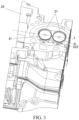
FIG. 3 is a schematic perspective view of a cylinder head in an engine according to an embodiment of the present disclosure; -
FIG. 4 is a schematic partial enlarged view at an intake valve hole of a cylinder head inFIG. 3 ; -
FIG. 5(a) is a schematic plan view of intake and exhaust valve holes of a cylinder head in an engine according to an embodiment of the present disclosure; -
FIG. 5(b) is a schematic perspective view of a combustion chamber of a cylinder head (the portion of the combustion chamber in the cylinder head) in an engine according to an embodiment of the present disclosure; -
FIG. 6 is a schematic sectional view of a cylinder head in an engine according to an embodiment of the present disclosure; -
FIG. 7 is a schematic partial enlarged view of part B inFIG. 6 ; -
FIG. 8 is another schematic sectional view of an engine according to an embodiment of the present disclosure; -
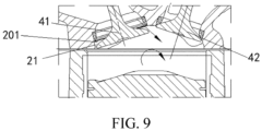
FIG. 9 is a schematic partial enlarged view of part C inFIG. 8 ; -
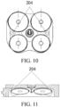
FIG. 10 is a schematic partial plan view of a cylinder head in an engine according to an embodiment of the present disclosure; -
FIG. 11 is a schematic partial sectional view of a cylinder head in an engine according to an embodiment of the present disclosure; -
FIG. 12 is a schematic sectional view of an engine perpendicular to a second direction according to an embodiment of the present disclosure; -
FIG. 13 is a schematic sectional view of an engine perpendicular to a first direction according to an embodiment of the present disclosure; -
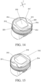
FIG. 14 is a schematic perspective view of a piston in an engine according to an embodiment of the present disclosure, viewed from a first perspective; -
FIG. 15 is a schematic perspective view of a piston in an engine according to an embodiment of the present disclosure, viewed from a second perspective; -
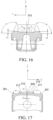
FIG. 16 is a schematic sectional view of a piston in an engine perpendicular to a first direction according to an embodiment of the present disclosure; -
FIG. 17 is a schematic sectional view of a piston in an engine perpendicular to a second direction according to an embodiment of the present disclosure; -
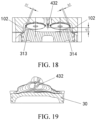
FIG. 18 is a schematic partial enlarged view of part D inFIG. 13 ; -
FIG. 19 is a schematic view showing the air flow between a piston and a spark plug in an engine according to an embodiment of the present disclosure; -
FIG. 20 is a schematic perspective view of a stereo-model corresponding to a combustion chamber in an engine according to an embodiment of the present disclosure; -
FIG. 21 is a schematic plan view of a stereo-model corresponding to a combustion chamber in an engine according to an embodiment of the present disclosure; -
FIG. 22 is a schematic sectional view taken along A-A inFIG. 21 ; and -
FIG. 23 is a schematic sectional view taken along B-B inFIG. 21 . - To make the objects, technical solutions, and advantages of the present disclosure clearer, the present disclosure will be described in further detail with reference to accompanying drawings and embodiments. It should be understood that the specific embodiments described herein are merely intended to explain the present disclosure instead of limiting the present disclosure.
- It should be noted that, when an element is referred to as being "fixed to" or "provided on" another element, the element may be directly on the other element, or an intermediate element may exist between the element and the other element. When an element is referred to as being "connected to" another element, the element may be directly connected to the other element, or an intermediate element may exist between the element and the other element.
- It should also be noted that, the orientation expressions "left", "right", "upper", "lower" or the like in the embodiments of the present disclosure are used merely in a mutually relative conception or with reference to the normal state of use of the product and shall not be regarded as limitation.
- As shown in
FIG. 1 to FIG. 4 andFIG. 8 , an embodiment of the present disclosure provides an engine. The engine includes acylinder block 10, acylinder head 20 and apiston 30. Thecylinder head 20 is fixedly connected to thecylinder block 10 and thepiston 30 is movably connected to thecylinder block 10. Thecylinder block 10, thecylinder head 20 and thepiston 30 form acombustion chamber 101. Anintake valve hole 201 and anexhaust valve hole 202 are defined on thecylinder head 20. Anintake valve 41 is provided at theintake valve hole 201 and anexhaust valve 42 is provided at theexhaust valve hole 202. Aprotrusion barrier protrusion 21 is provided at the edge of theintake valve hole 201 away from theexhaust valve hole 202. An included angle T between connecting lines that are formed with both ends of thebarrier protrusion 21 and a center of the intake valve hole 201 (i.e., the central angle corresponding to thebarrier protrusion 21, also called wrap angle) is greater than 120 degrees and less than or equal to 180 degrees. Thebarrier protrusion 21 has a certain height and forms a kind of barrier in combination with the head of theintake valve 41. Thebarrier protrusion 21 serves to impede and guide the air flow, so that the tumble effect of the air flow in the cylinder (the combustion chamber 101) is improved, resulting in a high tumble ratio, and the combustion speed is increased, more complete combustion is achieved and the after-combustion period is shortened, thereby facilitating improvement in the thermal efficiency of the engine. - Specifically, as shown in
FIG. 6 andFIG. 7 , the gap a between the outer diameter of theintake valve 41 and thebarrier protrusion 21 is 0.5 mm to 1 mm, which facilitates increasing the tumble ratio. - Specifically, as shown in
FIG. 6 andFIG. 7 , the side wall of thebarrier protrusion 21 is denoted by 21c inFIG. 7 and the end surface of thebarrier protrusion 21 is denoted by 21d. The height by which theintake valve 41 protrudes from theintake valve hole 201 is the head height h1 of theintake valve 41. The distance h2 between half way (h1 divided by 2, i.e., h1/2) of the head height of theintake valve 41 and the end surface of thebarrier protrusion 21 in the direction of the axis of theintake valve 41 is 2 mm to 3 mm, resulting in better tumble effect of the air flow in the cylinder. - Specifically, in an engine, at least two
combustion chambers 101 are provided. Two intake valve holes 201 and two exhaust valve holes 202 corresponding to each of thecombustion chambers 101 are defined on thecylinder head 20. - The two intake valve holes 201 are provided adjacent to each other on one side of the center of the
combustion chamber 101 and the two exhaust valve holes 202 are provided adjacent to each other on the other side of the center of thecombustion chamber 101. Aspark plug hole 203 may be defined on thecylinder head 20 at a position corresponding to the center of thecombustion chamber 101. The barrier protrusions 21 at the two intake valve holes 201 for thesame combustion chamber 101 are arranged symmetrically relative to each other, which provides better impedance and guidance of the air flow - Specifically, as shown in
FIG. 3 andFIG. 4 , the straight line passing through the centers of the two intake valve holes 201 is used as the reference axis L for thesame combustion chamber 101. Thebarrier protrusion 21 is located on the side of the reference axis L away from theexhaust valve hole 202 and neither end of thebarrier protrusion 21 exceeds the reference axis L, resulting in a reasonable structure. The two intake valve holes 201 of thesame combustion chamber 101 may be arranged along the direction from the front end to the back end of the engine. Accordingly, the two exhaust valve holes 202 of thesame combustion chamber 101 may also be arranged along the direction from the front end to the back end of the engine. - Specifically, as shown in
FIG. 3 andFIG. 4 , one end of thebarrier protrusion 21 is thefirst end 21a and the other end of thebarrier protrusion 21 is thesecond end 21b. Thefirst end 21a of thebarrier protrusion 21 is close to the other corresponding intake valve hole 201 (for the same combustion chamber 101) and the vertical distance L1 between thefirst end 21a of thebarrier protrusion 21 and the reference axis L is greater than the vertical distance L2 between thesecond end 21b of thebarrier protrusion 21 and the reference axis L. That is, thebarrier protrusion 21 as a whole may be biased toward the outside. As shown inFIG. 5(a) , the wrap angle of thebarrier protrusion 21 is inside the shaded region (with gridded hatches). The left to right direction inFIG. 5(a) represents the direction from the front side to the rear side of the engine. The direction of the reference line L inFIG. 4 represents the direction from the front side to the rear side of the engine.FIG. 5(b) shows a perspective view of a combustion chamber of the cylinder head. In this figure, 20a represents a portion close to the intake side and 20b represents a portion close to the exhaust side. Through ingenious arrangement of the range of the wrap angle of thebarrier protrusion 21, theintake valve 41 is enabled to improve the tumble effect of the air flow in the cylinder (such as the direction of tumble of the air flow represented by the arrow inFIG. 9 ) during small valve lift and consequently increase the combustion speed. - Specifically, at least two
measurement platforms 204 are provided on thecylinder head 20. The at least twomeasurement platforms 204 are provided on the two sides of the center of the combustion chamber 101 (i.e., the two sides of the spark plug hole 203) respectively. The surface of the combustion chamber of the cylinder head may be a cast blank surface. To ensure accurate measurement of the volume of thecombustion chamber 101, thecylinder head 20 in this embodiment, as shown inFIG. 10 and FIG. 11 , is designed to have twomeasurement platforms 204 inside. In the process of production, the volume of thecombustion chamber 101 can be indirectly controlled by measuring the height H0 from themeasurement platforms 204 to the end surface of thecylinder head 20, so that unqualified products can be prevented from being released. - Specifically, a
cylinder gasket 11 may be provided between thecylinder head 20 and thecylinder block 10. Thecylinder block 10 is provided with a cylinderbore side wall 102. Thespark plug 43 may be provided at the central position of the combustion chamber of the cylinder head. Thespark plug 43 includes acentral electrode 431 and aside electrode 432. - Specifically, as shown in
FIG. 12 to FIG. 17 , a squishing and guiding structure is provided on the top of thepiston 30 to further improve the tumble effect of the air flow in the cylinder (the combustion chamber 101). - Specifically, the
piston 30 has anupper reference plane 301. The squishing and guiding structure is of a protrusion shape relative to theupper reference plane 301 of thepiston 30. The upper reference plane of thepiston 30 may be a plane. The squishing and guiding structure is provided with a first squishing and guidingsurface 311 and a second squishing and guidingsurface 312 respectively on the two sides thereof in the first direction (i.e., the X direction inFIG. 14 ). The first squishing and guidingsurface 311 is relatively close to theintake valve 41 and the second squishing and guidingsurface 312 is relatively close to theexhaust valve 42. In thesame combustion chamber 101, anintake valve 41 and anexhaust valve 42 adjacent to each other are arranged in the first direction. In thesame combustion chamber 101, oneintake valve 41 and theother intake valve 41 are arranged in the second direction (i.e., the Y direction inFIG. 14 ). The first direction and the second direction are perpendicular to each other and the first direction and the second direction and the height direction (the Z direction) are perpendicular to each other. The squishing and guiding structure is provided with a first squishing and guidingprotrusion structure 313 and a second squishing and guidingprotrusion structure 314 respectively on the two sides thereof in the second direction. The first squishing and guidingprotrusion structure 313 and the second squishing and guidingprotrusion structure 314 protrudes relative to theupper reference plane 301. The first direction and the second direction and the movement direction (i.e., the height direction, the Z direction) of thepiston 30 are perpendicular to each other. The first squishing and guidingsurface 311 is relatively close to the intake side and the second squishing and guidingsurface 312 is relatively close to the exhaust side. The first squishing and guidingprotrusion structure 313 is relatively close to the front end of the engine and the second squishing and guidingprotrusion structure 314 is relatively close to the rear end of the engine. When thepiston 30 is at the top dead center (as shown inFIG. 12 andFIG. 13 ), the squishing and guiding structure will move into the correspondingcombustion chamber 101 of thecylinder head 20, thereby reducing the volume of thecombustion chamber 101 and increasing the geometric compression ratio of the engine. Also, as shown inFIG. 18 , when thepiston 30 is at the top dead center, gaps b1 and b2 are present between theside wall 102 of the combustion chamber of the cylinder head and the squishing and guiding structure (the first squishing and guidingprotrusion structure 313 and the second squishing and guidingprotrusion structure 314 of the squishing and guiding structure). The gaps b1 and b2 are located at the edge of thecombustion chamber 101 and can produce a squishing effect. By using the squishing and guiding structure and the squishing function, the turbulent kinetic energy at the edge of thecombustion chamber 101 can be increased, so that the combustion speed is increased and the tendency of knock of an engine of high compression ratio is mitigated. - In specific application, the first squishing and guiding
protrusion structure 313 and the second squishing and guidingprotrusion structure 314 in the front to rear direction (second direction) of thepiston 30 may be structures that are symmetrical to each other. - In specific application, the tops of the first squishing and guiding
protrusion structure 313 and the second squishing and guidingprotrusion structure 314 may each be of a planar shape. The outer sides of the first squishing and guidingprotrusion structure 313 and the second squishing and guidingprotrusion structure 314 may each be of a sloped shape, with rounded transition at the junction. It can be understood that rounded transition may also be adopted at the junction between the first squishing and guidingsurface 311, the second squishing and guidingsurface 312 and theupper reference plane 301. - Specifically, the top of the squishing and guiding structure is provided with a
pit structure 315. Thepit structure 315 is located between the first squishing and guidingprotrusion structure 313 and the second squishing and guidingprotrusion structure 314 and between the first squishing and guidingsurface 311 and the second squishing and guidingsurface 312. Thepit structure 315 may be of a concave arc shape, which facilitates tumbling of the air flow, so that the combustion speed can be increased. Furthermore, thepit structure 315 is concaved, which ensures the distance between thespark plug 43 and the top of the piston, facilitating preliminary formation of the fire core. Alternatively, thepit structure 315 may be of a curved shape or a spherical shape or the like. In this embodiment, thepit structure 315 is of a concave arc shape, and the bottom of thepit structure 315 may be higher than theupper reference plane 301. - Specifically, the first squishing and guiding
surface 311 and the second squishing and guidingsurface 312 may each be of a sloped shape or a curved shape or the like. The first squishing and guidingsurface 311 is provided with an intake valve avoidance structure. In this embodiment, two intake valve avoidance structures are provided, including a front intakevalve avoidance structure 316 and a rear intakevalve avoidance structure 317. The front intakevalve avoidance structure 316 and the rear intakevalve avoidance structure 317 are provided along the second direction at the junction between the first squishing and guidingsurface 311 and theupper reference plane 301 to avoid interference with theintake valve 41. The number of the intake valve avoidance structures provided is equal to the number of theintake valves 41. If only oneintake valve 41 is provided, then one intake valve avoidance structure is provided. - Specifically, when the
piston 30 moves to the top dead center, the squishing and guiding structure inserts into thecombustion chamber 101 of thecylinder head 20, and the minimum distances between the first squishing and guidingprotrusion structure 313 and the second squishing and guidingprotrusion structure 314 and theside wall 102 of the corresponding combustion chamber of the cylinder head are both 1 mm to 2 mm (denoted by b1 and b2 inFIG. 8 ). - Specifically, when the piston travels to the top dead center, the minimum distance b1 between the first squishing and guiding protrusion structure 313 (at the junction between the first squishing and guiding
protrusion structure 313 and the upper reference plane 301) and thecylinder head 20 may be equal to the minimum distance b2 between the second squishing and guidingprotrusion structure 314 and thecylinder head 20, which provides good squishing and guiding effect and facilitates easy machining. - In this embodiment, the minimum distance b1 between the first squishing and guiding
protrusion structure 313 and thecylinder head 20 is 1.56 mm. - In this embodiment, the minimum distance b2 between the second squishing and guiding
protrusion structure 314 and thecylinder head 20 is 1.56 mm. - Specifically, the
upper reference plane 301 may be of a planar shape. The included angle between the outer side of the first squishing and guidingprotrusion structure 313 and theupper reference plane 301 is the first included angle (denoted by β1 inFIG. 16 ), and the included angle between the second squishing and guidingprotrusion structure 314 and theupper reference plane 301 is the second included angle (denoted by β2 inFIG. 16 ). The first included angle and the second included angle are 100 degrees to 120 degrees. - Specifically, the first included angle β1 is equal to the second included angle β2, which provides good squishing and guiding effect and facilitates easy machining.
- In this embodiment, the first included angle β1 is 112.5 degrees.
- In this embodiment, the second included angle β2 is 112.5 degrees.
- Specifically, the vertical distance between the top of the first squishing and guiding
protrusion structure 313 and theupper reference plane 301 is a first height h3 and the vertical distance between the top of the second squishing and guidingprotrusion structure 314 and theupper reference plane 301 is a second height h4. The first height h3 and the second height h4 are 4 to 6 mm. - Specifically, the first height h3 is equal to the second height h4, which provides good squishing and guiding effect and facilitates machining.
- In this embodiment, the first height h3 is 4.9 mm.
- In this embodiment, the second height h4 is 4.9 mm.
- Specifically, a
spark plug 43 is connected to thecylinder head 20, and the distance h5 between the bottom of the pit structure 315 (at the center) and thespark plug 43 is 5.5 mm to 6 mm (as shown inFIG. 18 ), facilitating preliminary formation of the fire core. - Specifically, as shown in
FIG. 16 , the bottom of thepit structure 315 is of a smooth curve shape along the section perpendicular to the first direction. As shown inFIG. 17 , the bottom of thepit structure 315 is of a flattened shape along the section perpendicular to the second direction. Such a structure facilitates converging of the air flow toward the center along the front-rear direction of the cylinder in the vicinity of the compression top dead center so as to form a combustible gas mixture with suitable concentration, thereby facilitating ignition of thespark plug 43. - Specifically, in this embodiment, the first squishing and guiding
surface 311 and the second squishing and guidingsurface 312 are both of a sloped shape and theupper reference plane 301 is of a planar shape. The included angle between the first squishing and guidingsurface 311 and theupper reference plane 301 is a third included angle β3 and the included angle between the second squishing and guidingsurface 312 and theupper reference plane 301 is a fourth included angle β4. The third included angle β3 and the fourth included angle β4 is 160 degrees to 170 degrees. - In this embodiment, the third included angle β3 is 163 degrees and the fourth included angle β4 is 162 degrees. A 163° slope is adopted for the third included angle β3 close to the intake side and a 162° slope is adopted for the fourth included angle β4 close to the exhaust side. As such, on one hand, the intake and
exhaust valves 42 can be avoided, ensuring a suitable gap to prevent physical interference; on the other hand, the air flow is enabled to form an approximately symmetrical dual-swirl squishing structure in the vicinity of the compression top dead center (as shown inFIG. 19 ), which, in conjunction with the flattened design for thepit structure 315 along the second direction, ensures that the speed of the nearby air flow is controlled to a suitable range<15 m/s at the moment of ignition, which facilitates preliminary formation of the fire core and stability of flame propagation. - Specifically, as shown in
FIG. 17 , thecenter 310 of the squishing and guiding structure is offset from thecenter 300 of the piston along the first direction toward theexhaust valve 42 by a set distance S1. That is, the protrusion on the top surface of thepiston 30 is biased from the center of thepiston 30 toward the exhaust side, as shown by the direction of the arrow inFIG. 17 . Such an arrangement facilitates increasing the air flow rate at the edge of the exhaust side, increasing the flame propagation speed, and significantly decreasing the probability of preignition and knock due to high temperature on the exhaust side. - As shown in
FIG. 17 , the outer sides of the first squishing and guidingprotrusion structure 313 and the second squishing and guidingprotrusion structure 314 form a steep flange on the top of thepiston 30, thereby providing significant squishing and guiding effects and facilitating shortening of the after-combustion period to improve the thermal efficiency of the engine. - In this embodiment, the
combustion chamber 101 may be applied to an engine with high geometric compression ratio (i.e., a high efficiency engine). The provided engine may be used as an engine with high geometric compression ratio (i.e., a high efficiency engine). When thepiston 30 moves to the vicinity of the compression top dead center, thespark plug 43 ignites so as to start the next stroke. Thecylinder head 20 is provided with anintake valve 41, aquad exhaust valve 42, ameasurement platform 204 and abarrier protrusion 21. There may be twointake valves 41 and twoquad exhaust valves 42. The surface of the combustion chamber of the cylinder head may be a cast blank surface. To ensure accurate measurements of the volume of thecombustion chamber 101, thecombustion chamber 101 is designed to have twomeasurement platforms 204 inside. In the process of blank production, the volume of the combustion chamber of the cylinder head is indirectly controlled by measuring the height from themeasurement platforms 204 to the end surface of thecylinder block 10, so that unqualified products can be prevented from being released. The combustion chamber of the cylinder head is designed to have twobarrier protrusions 21 on theintake valve 41 close to the bottom side of thecylinder head 20. The barrier protrusions 21 have a certain height so as to form a barrier to impede and guide the air flow. Due to the effect of the structure of thecombustion chamber 101, the range of the wrap angle of the barrier protrusions 21 is arranged ingeniously, so that theintake valve 41 can improve the tumble effect of the air flow in the cylinder (such as the tumble direction of the air flow represented by the arrow inFIG. 9 ) during small valve lift and consequently the combustion speed is increased, resulting in more complete combustion. - The
piston 30 may be anAtkinson piston 30. The first squishing and guidingprotrusion structure 313 on the front side, the second squishing and guidingprotrusion structure 314 on the rear side, the front intakevalve avoidance structure 316 on the front side, the rear intakevalve avoidance structure 317 on the rear side, theupper reference plane 301 of thepiston 30 and the first squishing and guidingsurface 311 of thepiston 30 close to the intake side form jointly an intake-gas squishing and guiding device that provides reasonable tumble and swirl for combustion. Thepit structure 315 on the top of thepiston 30, while participating in squishing and guiding, provides a reasonable ignition gap for theside electrode 432 of thespark plug 43, which facilitates formation of the flame core and stability of the ignited gas mixture. Theupper reference plane 301 of thepiston 30, the second squishing and guidingsurface 312 of thepiston 30 close to the exhaust side and thepit structure 315 on the top of thepiston 30 provide jointly squishing and guiding for the exhaust gas.FIG. 20 to FIG. 23 show schematic perspective views of a stereo-model for a combustion chamber. - An embodiment of the present disclosure further provides a vehicle having the engine described above.
- In the engine and the vehicle having the engine according to embodiments of the present disclosure, a
barrier protrusion 21 provided at theintake valve hole 201 serves to impede and guide the air flow, so that the tumble effect of the air flow in the cylinder (the combustion chamber 101) is improved, resulting in a high tumble ratio, the combustion speed is increased, and more complete combustion is achieved and the after-combustion period is shortened, thereby facilitating improvement in the thermal efficiency of the engine. Also, in the squishing and guiding structure of thepiston 30, the first squishing and guidingprotrusion structure 313 on the front side, the second squishing and guidingprotrusion structure 314 on the rear side, the front intakevalve avoidance structure 316 on the front side, the rear intakevalve avoidance structure 317 on the rear side, theupper reference plane 301 of thepiston 30 and the first squishing and guidingsurface 311 of thepiston 30 close to the intake side form jointly an intake-gas squishing and guiding device that provides reasonable tumble and swirl for combustion. Thepit structure 315 on the top of thepiston 30, while participating in squishing and guiding, provides a reasonable ignition gap for theside electrode 432 of thespark plug 43, which facilitates formation of the flame core and stability of the ignited gas mixture. Theupper reference plane 301 of thepiston 30, the second squishing and guidingsurface 312 of thepiston 30 close to the exhaust side and thepit structure 315 on the top of thepiston 30 provide jointly squishing and guiding for the exhaust. With the structure described above and the squishing function thereof, the turbulent kinetic energy at the edge of the combustion chamber can be increased, so that the combustion speed can be increased and the tendency of knock of an engine with high compression ratio can be mitigated. Meanwhile, the barrier protrusion structure provided on the cylinder head increases the tumble ratio and consequently increases the combustion speed. With both arrangements, the after-combustion period is shortened and the thermal efficiency of the engine is improved. - Described above are merely preferred embodiments of the present disclosure, which are not intended to limit the present disclosure. Any modification, equivalent replacement or improvement made within the spirit and principle of the present disclosure shall fall within the protection scope of the present disclosure.
Claims (19)
- An engine, comprising a cylinder block, a cylinder head and a piston, the cylinder head fixedly connected to the cylinder block, the piston being movably connected to the cylinder block, the cylinder block, the cylinder head and the piston forming a combustion chamber;
an intake valve hole and an exhaust valve hole being defined on the cylinder head, an intake valve being provided at the intake valve hole and an exhaust valve being provided at the exhaust valve hole, a protruded barrier protrusion being provided at an edge of the intake valve hole away from the exhaust valve hole, an included angle between connecting lines that are formed with both ends of the barrier protrusion and a center of the intake valve hole being greater than 120 degrees and less than or equal to 180 degrees. - The engine according to claim 1, wherein a gap between an outer diameter of the intake valve and the barrier protrusion is 0.5 mm to 1 mm.
- The engine according to claim 1, wherein a height by which the intake valve protrudes from the intake valve hole is a head height of the intake valve, and a distance between half way of the head height of the intake valve and an end surface of the barrier protrusion in a direction of an axis of the intake valve is 2 mm to 3 mm.
- The engine according to claim 1, wherein at least two combustion chambers are provided, and a spark plug hole, two intake valve holes and two exhaust valve holes corresponding to each of the at least two combustion chambers are defined on the cylinder head; and
the two intake valve holes are defined adjacent to each other on one side of the spark plug hole at a center of the combustion chamber and the two exhaust valve holes are defined adjacent to each other on the other side of the spark plug hole at the center of the combustion chamber, and the barrier protrusions at the two intake valve holes are arranged symmetrically. - The engine according to claim 4, wherein a straight line passing through centers of the two intake valve holes is a reference axis, the barrier protrusion is located on a side of the reference axis away from the exhaust valve hole and neither end of the barrier protrusion exceeds the reference axis.
- The engine according to claim 5, wherein one end of the barrier protrusion is a first end and the other end of the barrier protrusion is a second end, wherein the first end of the barrier protrusion is close to the other corresponding intake valve hole and a vertical distance between the first end of the barrier protrusion and the reference axis is greater than a vertical distance between the second end of the barrier protrusion and the reference axis.
- The engine according to claim 1, wherein the cylinder head is provided with at least two measurement platforms.
- The engine according to any one of claims 1 to 7, wherein a squishing and guiding structure is provided on a top of the piston.
- The engine according to claim 8, wherein the squishing and guiding structure is of a shape protruding relative to an upper reference plane of the piston;the squishing and guiding structure is provided with a first squishing and guiding surface and a second squishing and guiding surface on two sides of a first direction respectively, the first squishing and guiding surface is relatively close to the intake valve and the second squishing and guiding surface is relatively close to the exhaust valve; andthe squishing and guiding structure is provided with a first squishing and guiding protrusion structure and a second squishing and guiding protrusion structure on two sides of a second direction respectively,wherein the first direction is perpendicular to the second direction.
- The engine according to claim 9, wherein a pit structure is provided on a top of the squishing and guiding structure, and the pit structure is located between the first squishing and guiding protrusion structure and the second squishing and guiding protrusion structure.
- The engine according to claim 10, wherein the first squishing and guiding surface and the second squishing and guiding surface are of a sloped shape or a curved shape; and
an intake valve avoidance structure is provided on the first squishing and guiding surface. - The engine according to claim 10, wherein when the piston moves to a top dead center, the squishing and guiding structure inserts into the combustion chamber of the cylinder head, and minimum distances between each of the first squishing and guiding protrusion structure and the second squishing and guiding protrusion structure and a side wall of the corresponding combustion chamber of the cylinder head are both 1 mm to 2 mm.
- The engine according to claim 10, wherein the upper reference plane is of a planar shape, an included angle between an outer side of the first squishing and guiding protrusion structure and the upper reference plane is a first included angle and an included angle between the second squishing and guiding protrusion structure and the upper reference plane is a second included angle, and the first included angle and the second included angle are 100 degrees to 120 degrees.
- The engine according to claim 10, wherein a vertical distance between a top of the first squishing and guiding protrusion structure and the upper reference plane is a first height and a vertical distance between a top of the second squishing and guiding protrusion structure and the upper reference plane is a second height, and each of the first height and the second height are 4 mm to 6 mm.
- The engine according to claim 10, wherein a spark plug is connected to the cylinder head and a distance between a bottom of the pit structure and the spark plug is 5.5 mm to 6 mm.
- The engine according to claim 10, wherein the bottom of the pit structure is of a smooth curve shape along a cross section perpendicular to the first direction; and the bottom of the pit structure is of a flattened shape along a cross section perpendicular to the second direction.
- The engine according to claim 10, wherein the first squishing and guiding surface and the second squishing and guiding surface are both of a sloped shape and the upper reference plane is of a planar shape, an included angle between the first squishing and guiding surface and the upper reference plane is a third included angle and an included angle between the second squishing and guiding surface and the upper reference plane is a fourth included angle, and the third included angle and the fourth included angle are 160 degrees to 170 degrees.
- The engine according to claim 10, wherein a center of the squishing and guiding structure is offset from a center of the piston toward the exhaust valve by a set distance in the first direction.
- A vehicle, comprising the engine according to any one of claims 1 to 18.
Applications Claiming Priority (2)
| Application Number | Priority Date | Filing Date | Title |
|---|---|---|---|
| CN202110226757.2A CN114991943A (en) | 2021-03-01 | 2021-03-01 | An engine and a vehicle having the same |
| PCT/CN2022/073200 WO2022183868A1 (en) | 2021-03-01 | 2022-01-21 | Engine and vehicle with engine |
Publications (3)
| Publication Number | Publication Date |
|---|---|
| EP4257811A1 true EP4257811A1 (en) | 2023-10-11 |
| EP4257811A4 EP4257811A4 (en) | 2024-06-12 |
| EP4257811B1 EP4257811B1 (en) | 2025-12-24 |
Family
ID=83018417
Family Applications (1)
| Application Number | Title | Priority Date | Filing Date |
|---|---|---|---|
| EP22762336.0A Active EP4257811B1 (en) | 2021-03-01 | 2022-01-21 | Engine and vehicle with engine |
Country Status (6)
| Country | Link |
|---|---|
| US (1) | US11952957B2 (en) |
| EP (1) | EP4257811B1 (en) |
| CN (1) | CN114991943A (en) |
| AU (1) | AU2022228272B2 (en) |
| ES (1) | ES3059010T3 (en) |
| WO (1) | WO2022183868A1 (en) |
Families Citing this family (2)
| Publication number | Priority date | Publication date | Assignee | Title |
|---|---|---|---|---|
| CN116066254A (en) * | 2023-02-02 | 2023-05-05 | 中国第一汽车股份有限公司 | Combustion system and vehicle with same |
| CN119664486B (en) * | 2024-12-03 | 2025-10-28 | 一汽解放汽车有限公司 | Combustion chamber and engine |
Family Cites Families (16)
| Publication number | Priority date | Publication date | Assignee | Title |
|---|---|---|---|---|
| EP0554235A1 (en) * | 1992-01-29 | 1993-08-04 | AVL Gesellschaft für Verbrennungskraftmaschinen und Messtechnik mbH.Prof.Dr.Dr.h.c. Hans List | Two stroke engine with at least one inlet and one exhaust valve per cylinder |
| DE19535147C2 (en) * | 1995-09-21 | 2002-07-11 | Meta Motoren Energietech | Reciprocating internal combustion engine with at least one cylinder |
| JP3906963B2 (en) * | 2000-09-12 | 2007-04-18 | 本田技研工業株式会社 | Combustion chamber structure of internal combustion engine |
| EP1217186B1 (en) * | 2000-12-20 | 2015-07-29 | Institut Français du Pétrole | Direct injection engine with small spray angle and methods of using such an engine |
| JP2004293484A (en) * | 2003-03-28 | 2004-10-21 | Mazda Motor Corp | Spark ignition engine |
| FR2869359B1 (en) * | 2004-04-22 | 2008-08-22 | Renault Sas | ADMISSION CIRCUIT COMPRISING AN ORIFICE PROVIDED WITH AN ENTAIL FOR CONFERING AN ENOUGH GAS TOURBILLONARY MOVEMENT |
| JP4165516B2 (en) * | 2005-02-18 | 2008-10-15 | 三菱自動車工業株式会社 | Combustion chamber structure of internal combustion engine |
| JP4556771B2 (en) * | 2005-05-27 | 2010-10-06 | 三菱自動車工業株式会社 | Engine combustion chamber structure |
| DE102012103206B4 (en) * | 2012-04-13 | 2017-08-03 | Caterpillar Energy Solutions Gmbh | Piston of an internal combustion engine |
| US9038592B2 (en) * | 2013-04-16 | 2015-05-26 | Deere & Company | Cylinder head comprising a shroud |
| CN106640338B (en) * | 2016-12-28 | 2019-03-08 | 天津大学 | A kind of overhead valve two-stroke directly spraying petrol engine combustion camber in cylinder |
| CN106870120A (en) * | 2017-03-21 | 2017-06-20 | 中国第汽车股份有限公司 | A kind of high-efficiency engine combustion system |
| CN207777011U (en) * | 2018-01-04 | 2018-08-28 | 中国第一汽车股份有限公司 | Cylinder cover of petrol engine combustion chamber |
| JP2019190286A (en) * | 2018-04-18 | 2019-10-31 | トヨタ自動車株式会社 | Cylinder head for internal combustion engine |
| CN109281750B (en) * | 2018-09-25 | 2020-08-18 | 宁波吉利罗佑发动机零部件有限公司 | A high compression ratio engine combustion chamber |
| CN109538369B (en) * | 2019-01-15 | 2024-10-29 | 李斯特技术中心(上海)有限公司 | Piston and top shape thereof |
-
2021
- 2021-03-01 CN CN202110226757.2A patent/CN114991943A/en active Pending
-
2022
- 2022-01-21 ES ES22762336T patent/ES3059010T3/en active Active
- 2022-01-21 AU AU2022228272A patent/AU2022228272B2/en active Active
- 2022-01-21 EP EP22762336.0A patent/EP4257811B1/en active Active
- 2022-01-21 WO PCT/CN2022/073200 patent/WO2022183868A1/en not_active Ceased
-
2023
- 2023-06-26 US US18/214,429 patent/US11952957B2/en active Active
Also Published As
| Publication number | Publication date |
|---|---|
| WO2022183868A1 (en) | 2022-09-09 |
| CN114991943A (en) | 2022-09-02 |
| AU2022228272A1 (en) | 2023-07-20 |
| ES3059010T3 (en) | 2026-03-16 |
| US11952957B2 (en) | 2024-04-09 |
| US20230332556A1 (en) | 2023-10-19 |
| EP4257811A4 (en) | 2024-06-12 |
| AU2022228272B2 (en) | 2025-04-10 |
| EP4257811B1 (en) | 2025-12-24 |
Similar Documents
| Publication | Publication Date | Title |
|---|---|---|
| US20230332556A1 (en) | Engine and vehicle having the same | |
| JP7388224B2 (en) | Internal combustion engine with prechamber | |
| CN100535436C (en) | Combustion chamber structure of an internal combustion engine | |
| CN113586227A (en) | Combustion chamber structure of gasoline engine and gasoline engine | |
| CN102042074B (en) | Spark-ignited internal combustion engine | |
| CN114017194B (en) | A kind of ignition compression ignition gasoline engine piston and engine | |
| CN212563446U (en) | A medium and heavy-duty ignition engine combustion chamber | |
| US4359981A (en) | High compression type internal combustion engine | |
| JPS5838610B2 (en) | internal combustion engine | |
| US6701883B2 (en) | Cylinder head for use on a spark-ignition internal combustion engine and such spark-ignition internal combustion engine | |
| CN109751114B (en) | Combustion chamber structure of internal combustion engine | |
| JPS5845572B2 (en) | Combustion chamber of internal combustion engine | |
| JPS5857613B2 (en) | internal combustion engine | |
| CN107339150A (en) | A kind of engine chamber for using Fuel Petroleum instead on the basis of diesel engine | |
| CN115059538A (en) | Inclined Omega Combustion Chamber for Opposed Piston Engines with Single Sided Spray Jet Ignition | |
| US11624313B2 (en) | Engine with combustion chamber | |
| WO2022236457A1 (en) | Combustion system for vehicle and vehicle | |
| CN111878221A (en) | A medium and heavy-duty ignition engine combustion chamber | |
| CN212716878U (en) | Combustion chamber of engine | |
| JPS5840257Y2 (en) | Combustion chamber of a fuel-injected internal combustion engine | |
| CN212716877U (en) | Combustion chamber of engine | |
| CN111749783A (en) | Engine air intake and engine cylinder head and engine | |
| JPS6314023Y2 (en) | ||
| WO2018180130A1 (en) | Spark-ignition internal combustion engine | |
| CN118273803A (en) | Vehicle engine, vehicle engine design evaluation method, and vehicle |
Legal Events
| Date | Code | Title | Description |
|---|---|---|---|
| STAA | Information on the status of an ep patent application or granted ep patent |
Free format text: STATUS: THE INTERNATIONAL PUBLICATION HAS BEEN MADE |
|
| PUAI | Public reference made under article 153(3) epc to a published international application that has entered the european phase |
Free format text: ORIGINAL CODE: 0009012 |
|
| STAA | Information on the status of an ep patent application or granted ep patent |
Free format text: STATUS: REQUEST FOR EXAMINATION WAS MADE |
|
| 17P | Request for examination filed |
Effective date: 20230630 |
|
| AK | Designated contracting states |
Kind code of ref document: A1 Designated state(s): AL AT BE BG CH CY CZ DE DK EE ES FI FR GB GR HR HU IE IS IT LI LT LU LV MC MK MT NL NO PL PT RO RS SE SI SK SM TR |
|
| DAV | Request for validation of the european patent (deleted) | ||
| DAX | Request for extension of the european patent (deleted) | ||
| A4 | Supplementary search report drawn up and despatched |
Effective date: 20240515 |
|
| RIC1 | Information provided on ipc code assigned before grant |
Ipc: F02F 3/28 20060101ALI20240508BHEP Ipc: F02F 1/42 20060101ALI20240508BHEP Ipc: F02B 23/08 20060101ALI20240508BHEP Ipc: F02B 31/04 20060101AFI20240508BHEP |
|
| GRAP | Despatch of communication of intention to grant a patent |
Free format text: ORIGINAL CODE: EPIDOSNIGR1 |
|
| STAA | Information on the status of an ep patent application or granted ep patent |
Free format text: STATUS: GRANT OF PATENT IS INTENDED |
|
| INTG | Intention to grant announced |
Effective date: 20250911 |
|
| GRAS | Grant fee paid |
Free format text: ORIGINAL CODE: EPIDOSNIGR3 |
|
| GRAA | (expected) grant |
Free format text: ORIGINAL CODE: 0009210 |
|
| STAA | Information on the status of an ep patent application or granted ep patent |
Free format text: STATUS: THE PATENT HAS BEEN GRANTED |
|
| AK | Designated contracting states |
Kind code of ref document: B1 Designated state(s): AL AT BE BG CH CY CZ DE DK EE ES FI FR GB GR HR HU IE IS IT LI LT LU LV MC MK MT NL NO PL PT RO RS SE SI SK SM TR |
|
| REG | Reference to a national code |
Ref country code: CH Ref legal event code: F10 Free format text: ST27 STATUS EVENT CODE: U-0-0-F10-F00 (AS PROVIDED BY THE NATIONAL OFFICE) Effective date: 20251224 Ref country code: GB Ref legal event code: FG4D |
|
| REG | Reference to a national code |
Ref country code: DE Ref legal event code: R096 Ref document number: 602022027489 Country of ref document: DE |
|
| P01 | Opt-out of the competence of the unified patent court (upc) registered |
Free format text: CASE NUMBER: UPC_APP_0002416_4257811/2026 Effective date: 20260123 |
|
| REG | Reference to a national code |
Ref country code: ES Ref legal event code: FG2A Ref document number: 3059010 Country of ref document: ES Kind code of ref document: T3 Effective date: 20260316 |
|
| PGFP | Annual fee paid to national office [announced via postgrant information from national office to epo] |
Ref country code: GB Payment date: 20260123 Year of fee payment: 5 |
|
| PGFP | Annual fee paid to national office [announced via postgrant information from national office to epo] |
Ref country code: ES Payment date: 20260227 Year of fee payment: 5 |
|
| REG | Reference to a national code |
Ref country code: LT Ref legal event code: MG9D |
|
| PG25 | Lapsed in a contracting state [announced via postgrant information from national office to epo] |
Ref country code: NO Free format text: LAPSE BECAUSE OF FAILURE TO SUBMIT A TRANSLATION OF THE DESCRIPTION OR TO PAY THE FEE WITHIN THE PRESCRIBED TIME-LIMIT Effective date: 20260324 |
|
| PGFP | Annual fee paid to national office [announced via postgrant information from national office to epo] |
Ref country code: DE Payment date: 20260121 Year of fee payment: 5 |
|
| PG25 | Lapsed in a contracting state [announced via postgrant information from national office to epo] |
Ref country code: HR Free format text: LAPSE BECAUSE OF FAILURE TO SUBMIT A TRANSLATION OF THE DESCRIPTION OR TO PAY THE FEE WITHIN THE PRESCRIBED TIME-LIMIT Effective date: 20251224 Ref country code: FI Free format text: LAPSE BECAUSE OF FAILURE TO SUBMIT A TRANSLATION OF THE DESCRIPTION OR TO PAY THE FEE WITHIN THE PRESCRIBED TIME-LIMIT Effective date: 20251224 |
|
| PGFP | Annual fee paid to national office [announced via postgrant information from national office to epo] |
Ref country code: AT Payment date: 20260301 Year of fee payment: 5 |
|
| PG25 | Lapsed in a contracting state [announced via postgrant information from national office to epo] |
Ref country code: RS Free format text: LAPSE BECAUSE OF FAILURE TO SUBMIT A TRANSLATION OF THE DESCRIPTION OR TO PAY THE FEE WITHIN THE PRESCRIBED TIME-LIMIT Effective date: 20260324 |
|
| PGFP | Annual fee paid to national office [announced via postgrant information from national office to epo] |
Ref country code: FR Payment date: 20260219 Year of fee payment: 5 |
|
| PG25 | Lapsed in a contracting state [announced via postgrant information from national office to epo] |
Ref country code: LV Free format text: LAPSE BECAUSE OF FAILURE TO SUBMIT A TRANSLATION OF THE DESCRIPTION OR TO PAY THE FEE WITHIN THE PRESCRIBED TIME-LIMIT Effective date: 20251224 |