EP4257805A1 - Rotor for an aircraft engine and compressor section of an aircraft engine - Google Patents
Rotor for an aircraft engine and compressor section of an aircraft engine Download PDFInfo
- Publication number
- EP4257805A1 EP4257805A1 EP23167152.0A EP23167152A EP4257805A1 EP 4257805 A1 EP4257805 A1 EP 4257805A1 EP 23167152 A EP23167152 A EP 23167152A EP 4257805 A1 EP4257805 A1 EP 4257805A1
- Authority
- EP
- European Patent Office
- Prior art keywords
- crack
- mitigator
- central axis
- extending
- rotor
- Prior art date
- Legal status (The legal status is an assumption and is not a legal conclusion. Google has not performed a legal analysis and makes no representation as to the accuracy of the status listed.)
- Pending
Links
- 239000007789 gas Substances 0.000 description 10
- 239000003570 air Substances 0.000 description 3
- 238000005516 engineering process Methods 0.000 description 3
- 239000000567 combustion gas Substances 0.000 description 2
- 239000000463 material Substances 0.000 description 2
- 238000012986 modification Methods 0.000 description 2
- 230000004048 modification Effects 0.000 description 2
- 230000007704 transition Effects 0.000 description 2
- 239000012080 ambient air Substances 0.000 description 1
- 238000004891 communication Methods 0.000 description 1
- 230000000694 effects Effects 0.000 description 1
- 239000000446 fuel Substances 0.000 description 1
- 238000000034 method Methods 0.000 description 1
- 230000002035 prolonged effect Effects 0.000 description 1
- 230000001902 propagating effect Effects 0.000 description 1
- 239000003351 stiffener Substances 0.000 description 1
Images


Classifications
-
- F—MECHANICAL ENGINEERING; LIGHTING; HEATING; WEAPONS; BLASTING
- F01—MACHINES OR ENGINES IN GENERAL; ENGINE PLANTS IN GENERAL; STEAM ENGINES
- F01D—NON-POSITIVE DISPLACEMENT MACHINES OR ENGINES, e.g. STEAM TURBINES
- F01D5/00—Blades; Blade-carrying members; Heating, heat-insulating, cooling or antivibration means on the blades or the members
- F01D5/02—Blade-carrying members, e.g. rotors
- F01D5/04—Blade-carrying members, e.g. rotors for radial-flow machines or engines
- F01D5/043—Blade-carrying members, e.g. rotors for radial-flow machines or engines of the axial inlet- radial outlet, or vice versa, type
- F01D5/048—Form or construction
-
- F—MECHANICAL ENGINEERING; LIGHTING; HEATING; WEAPONS; BLASTING
- F05—INDEXING SCHEMES RELATING TO ENGINES OR PUMPS IN VARIOUS SUBCLASSES OF CLASSES F01-F04
- F05D—INDEXING SCHEME FOR ASPECTS RELATING TO NON-POSITIVE-DISPLACEMENT MACHINES OR ENGINES, GAS-TURBINES OR JET-PROPULSION PLANTS
- F05D2220/00—Application
- F05D2220/30—Application in turbines
- F05D2220/32—Application in turbines in gas turbines
- F05D2220/323—Application in turbines in gas turbines for aircraft propulsion, e.g. jet engines
-
- F—MECHANICAL ENGINEERING; LIGHTING; HEATING; WEAPONS; BLASTING
- F05—INDEXING SCHEMES RELATING TO ENGINES OR PUMPS IN VARIOUS SUBCLASSES OF CLASSES F01-F04
- F05D—INDEXING SCHEME FOR ASPECTS RELATING TO NON-POSITIVE-DISPLACEMENT MACHINES OR ENGINES, GAS-TURBINES OR JET-PROPULSION PLANTS
- F05D2250/00—Geometry
- F05D2250/10—Two-dimensional
- F05D2250/14—Two-dimensional elliptical
- F05D2250/141—Two-dimensional elliptical circular
-
- F—MECHANICAL ENGINEERING; LIGHTING; HEATING; WEAPONS; BLASTING
- F05—INDEXING SCHEMES RELATING TO ENGINES OR PUMPS IN VARIOUS SUBCLASSES OF CLASSES F01-F04
- F05D—INDEXING SCHEME FOR ASPECTS RELATING TO NON-POSITIVE-DISPLACEMENT MACHINES OR ENGINES, GAS-TURBINES OR JET-PROPULSION PLANTS
- F05D2250/00—Geometry
- F05D2250/20—Three-dimensional
- F05D2250/29—Three-dimensional machined; miscellaneous
- F05D2250/294—Three-dimensional machined; miscellaneous grooved
-
- F—MECHANICAL ENGINEERING; LIGHTING; HEATING; WEAPONS; BLASTING
- F05—INDEXING SCHEMES RELATING TO ENGINES OR PUMPS IN VARIOUS SUBCLASSES OF CLASSES F01-F04
- F05D—INDEXING SCHEME FOR ASPECTS RELATING TO NON-POSITIVE-DISPLACEMENT MACHINES OR ENGINES, GAS-TURBINES OR JET-PROPULSION PLANTS
- F05D2250/00—Geometry
- F05D2250/70—Shape
- F05D2250/71—Shape curved
- F05D2250/711—Shape curved convex
-
- F—MECHANICAL ENGINEERING; LIGHTING; HEATING; WEAPONS; BLASTING
- F05—INDEXING SCHEMES RELATING TO ENGINES OR PUMPS IN VARIOUS SUBCLASSES OF CLASSES F01-F04
- F05D—INDEXING SCHEME FOR ASPECTS RELATING TO NON-POSITIVE-DISPLACEMENT MACHINES OR ENGINES, GAS-TURBINES OR JET-PROPULSION PLANTS
- F05D2250/00—Geometry
- F05D2250/70—Shape
- F05D2250/71—Shape curved
- F05D2250/712—Shape curved concave
-
- F—MECHANICAL ENGINEERING; LIGHTING; HEATING; WEAPONS; BLASTING
- F05—INDEXING SCHEMES RELATING TO ENGINES OR PUMPS IN VARIOUS SUBCLASSES OF CLASSES F01-F04
- F05D—INDEXING SCHEME FOR ASPECTS RELATING TO NON-POSITIVE-DISPLACEMENT MACHINES OR ENGINES, GAS-TURBINES OR JET-PROPULSION PLANTS
- F05D2260/00—Function
- F05D2260/94—Functionality given by mechanical stress related aspects such as low cycle fatigue [LCF] of high cycle fatigue [HCF]
- F05D2260/941—Functionality given by mechanical stress related aspects such as low cycle fatigue [LCF] of high cycle fatigue [HCF] particularly aimed at mechanical or thermal stress reduction
Definitions
- the application relates generally to aircraft engines and, more particularly, to rotors, such as compressor and turbine rotors, used in such engines.
- An aircraft engine rotor disc such as a compressor rotor disc or a turbine rotor disc, is subjected to low cycle fatigue which can result from centrifugal and/or thermal loads over extended periods.
- cracks may form on the disc due to such low cycle fatigue.
- the loading on the disc resolves into is a combination of radial and hoop stresses. Depending on location on the disc, one of the radial stress and the hoop stress dominates. At locations where the stress transitions from being radial dominant to hoop dominant, cracks may initiate at any angle. Cracks extending in a radial direction are undesired since they may propagate at undesired locations. Improvements are therefore sought.
- a rotor for an aircraft engine comprising: a hub extending circumferentially about a central axis, the hub having a bore, a gaspath-facing surface located radially outwardly of the bore relative to the central axis, a first face extending from the bore to the gaspath-facing surface, and a second face opposite the first face and extending from the bore to the gaspath-facing surface; blades circumferentially distributed about the central axis, the blades protruding away from the gaspath-facing surface of the hub; and a crack mitigator located on the first face, the crack mitigator extending circumferentially relative to the central axis, the crack mitigator extending axially from a baseline surface of the first face.
- the rotor as defined above and described herein may also include one or more of the following features, in whole or in part, and in any combination.
- the crack mitigator is located radially outwardly of a mid-plane of the first face, the mid-plane located halfway between the bore and a radially outward-most location of the gaspath-facing surface.
- the crack mitigator includes at least one groove extending in an axial direction relative to the central axis from the first face.
- the at least one groove has a depth (D1) extending in the axial direction and a height (H1) extending in a radial direction relative to the central axis, a ratio of the depth (D1) to the height (H1) ranging from 0.01 to 0.5.
- the at least one groove includes at least two grooves radially offset from one another.
- a ratio of a distance (S12) between the at least two grooves to a sum of heights (H1, H2) of the at least two grooves ranges from 0.25 to 5, the heights extending in a radial direction relative to the central axis.
- the crack mitigator includes at least one bump extending in an axial direction relative to the central axis from the first face.
- the at least one bump has a depth (D1) extending in the axial direction and a height (H1) extending in a radial direction relative to the central axis, a ratio of the depth (D1) to the height (H1) ranging from 0.01 to 0.5.
- the at least one bump includes at least two bumps radially offset from one another.
- a ratio of a distance (S12) between the at least two bumps to a sum of heights (H1, H2) of the at least two bumps ranges from 0.25 to 5, the heights extending in a radial direction relative to the central axis.
- the crack mitigator includes at least one bump and at least one groove.
- the bump and groove may have any of the features described above.
- the at least one bump is located radially outwardly of the at least one groove.
- a compressor section of an aircraft engine having an impeller rotatable about a central axis, the impeller comprising: a hub extending circumferentially about a central axis, the hub having a bore, a gaspath-facing surface located radially outwardly of the bore relative to the central axis, a first face extending from the bore to the gaspath-facing surface, and a second face opposite the first face and extending from the bore to the gaspath-facing surface; blades circumferentially distributed about the central axis, the blades protruding from the gaspath-facing surface of the hub; and a crack mitigator located on the first face and extending circumferentially about the central axis, the crack mitigator extending from a baseline surface of the first face.
- the compressor section as defined above and described herein may also include one or more of the following features, in whole or in part, and in any combination.
- the crack mitigator is located radially outwardly of a mid-plane of the first face, the mid-plane located halfway between the bore and a radially outward-most location of the gaspath-facing surface.
- the crack mitigator is at least one groove extending in an axial direction relative to the central axis from the first face, the at least one groove having a depth (D1) extending in the axial direction and a height (H1) extending in a radial direction relative to the central axis, a ratio of the depth (D1) to the height (H1) ranging from 0.01 to 0.5.
- the crack mitigator is at least one bump extending in an axial direction relative to the central axis from the first face, the at least one bump having a depth (D1) extending in the axial direction and a height (H1) extending in a radial direction relative to the central axis, a ratio of the depth (D1) to the height (H1) ranging from 0.01 to 0.5.
- the crack mitigator is a first crack mitigator, a second crack mitigator radially offset from the first crack mitigator, a ratio of a distance (S12) between the first crack mitigator and the second crack mitigator to a sum of heights (H1, H2) of the first crack mitigator and the second crack mitigator ranging from 0.25 to 5, the heights extending in a radial direction relative to the central axis.
- the crack mitigator is a first crack mitigator, a second crack mitigator radially offset from the first crack mitigator, the first crack mitigator being a bump, the second crack mitigator being a groove, the bump located radially outwardly of the groove.
- the crack mitigator is a first crack mitigator, a second crack mitigator radially offset from the first crack mitigator, the first crack mitigator being a bump, the second crack mitigator being a bump.
- the crack mitigator is a first crack mitigator, a second crack mitigator radially offset from the first crack mitigator, the first crack mitigator being a groove, the second crack mitigator being a groove.
- Fig. 1 illustrates an aircraft engine depicted as a gas turbine engine 10 of a type preferably provided for use in subsonic flight, generally comprising in serial flow communication a fan 12 through which ambient air is propelled, a compressor section 14 for pressurizing the air, a combustor 16 in which the compressed air is mixed with fuel and ignited for generating an annular stream of hot combustion gases, and a turbine section 18 for extracting energy from the combustion gases.
- the fan 12, the compressor section 14, and the turbine section 18 are rotatable about a central axis 11 of the gas turbine engine 10.
- the gas turbine engine 10 comprises a high-pressure spool having a high-pressure shaft 20 drivingly engaging a high-pressure turbine 18A of the turbine section 18 to a high-pressure compressor 14A of the compressor section 14, and a low-pressure spool having a low-pressure shaft 21 drivingly engaging a low-pressure turbine 18B of the turbine section to a low-pressure compressor 14B of the compressor section 14 and drivingly engaged to the fan 12.
- a high-pressure spool having a high-pressure shaft 20 drivingly engaging a high-pressure turbine 18A of the turbine section 18 to a high-pressure compressor 14A of the compressor section 14, and a low-pressure spool having a low-pressure shaft 21 drivingly engaging a low-pressure turbine 18B of the turbine section to a low-pressure compressor 14B of the compressor section 14 and drivingly engaged to the fan 12.
- the compressor section 14, more specifically the high-pressure compressor 14A includes an impeller I.
- the impeller I is rotatable about the central axis 11 for pressurizing air.
- the impeller I has a back face including three zones A, B, C disposed radially inward one another; zone C being the closest to the central axis 11.
- stresses imparted on the impeller I as a result of its rotation about the central axis 11 vary from being dominant in a circumferential direction or in a radial direction.
- a fatigue crack may form on a hub of the impeller I. Damage tolerance methods and tools can be used to determine the remaining crack propagation life and trajectory of the crack leading up to the need to replace the impeller I. Depending of where a crack initiates, it may affect the way said crack propagates. For instance, at higher and lower radii, such as within zones A and C, the dominant low-cycle fatigue stress is along a circumferential direction relative to the central axis 11 (i.e., hoop dominated). At a mid-radius location, such as within zone B, the dominant low-cycle fatigue stress is along a radial direction relative to the central axis 11. Length of arrows presented in Fig. 3 are indicative of which component of the stress is greater.
- ⁇ H denotes the hoop stress whereas ⁇ R denotes the radial stress.
- the bi-axiality ratio of hoop stress to radial stress
- This may occur between zones A and B and between zones B and C.
- the bi-axiality is equal to or proximate to one, cracks may theoretically initiate at any angle. If a crack initiates on the disc profile of a compressor, the resulting trajectory of the crack is a function of the initial crack orientation, and the resulting dominant LCF stress field.
- a crack When a crack initiates from a hoop dominated stress field (e.g., zones A or C) or where a bi-axiality ratio of one, the crack can initiate either in the radial direction, or at an angle. If a crack initiates at an angle and it is left to propagate, it may continue to grow at the same angle it initiated until it enters a unique stress field where both ends of the crack are dominated by hoop loading. This may result in the crack to turn on opposite ends in radially opposite directions.
- a hoop dominated stress field e.g., zones A or C
- a bi-axiality ratio of one the crack can initiate either in the radial direction, or at an angle. If a crack initiates at an angle and it is left to propagate, it may continue to grow at the same angle it initiated until it enters a unique stress field where both ends of the crack are dominated by hoop loading. This may result in the crack to turn on opposite ends in radially opposite directions.
- this crack When a crack initiates from a radially dominated stress field (e.g., zone B), this crack will likely be perpendicular to the radial load. When left to propagate, this crack may continue to grow perpendicular to the radial load until it enters a higher radius, where hoop loading begins to dominate. In this case, the hoop loading turns the crack such that both ends of the crack propagate radially outwardly toward a gaspath-facing surface of the impeller. For safety reasons, it is preferred to have a crack that propagate perpendicularly to the radial load and grow toward the gaspath-facing surface, instead of growing toward the bore.
- the radial load may never contribute to the growth of the crack. In some cases, only the hoop load may drive the growth of the crack toward the bore.
- the present disclosure proposes a rotor presenting crack mitigators, which may be in the form of bumps or grooves, that are used to reduce risks of cracks growing towards a bore of the rotor.
- the crack mitigators may introduce a stress concentration factor in a radial flow stress direction as well as increase the local nominal stress. This may help to maximise the radial contribution of crack growth.
- These crack mitigators may increase a size of an area on the impeller I where a crack would grow toward the gaspath-facing surface, instead of growing toward the bore.
- These crack mitigators may be used for compressor rotors where the resulting disc stresses may be low and the corresponding low cycle fatigue life may be high.
- the crack mitigators may be designed to avoid altering the minimum life of the rotor while minimizing risks of cracks propagating towards the bore.
- an impeller for gas turbine engine 10 of Fig. 1 is shown at 30.
- the impeller 30 may be part of the high-pressure compressor 14A. It will be appreciated that the principles of the present disclosure may apply to any rotor such as, for instance, a compressor rotor of an axial compressor, an impeller of a turbine section, a turbine rotor of an axial turbine, and so on.
- the impeller 30 has a hub 31 that extends circumferential about the central axis 11 of the gas turbine engine 10.
- the hub 31 has a bore 32 and a gaspath-facing surface 33 located radially outwardly of the bore 32 relative to the central axis 11.
- the hub 31 includes a front face 34 that extends from the bore 32 to the gaspath-facing surface 33.
- the hub 31 includes a back face 35 that extends from the bore 32 to the gaspath-facing surface 33.
- the impeller 30 includes blades 36 that are circumferentially distributed about the central axis 11. The blades 36 protrude from the gaspath-facing surface 33 of the hub 31.
- the impeller 30 has an inlet 30I that is oriented substantially axially relative to the central axis 11 and an outlet 30O that is oriented substantially radially relative to the central axis 11.
- the blades 36 and flow paths defined between each two adjacent ones of the blades 36 curve from a substantially axial orientation to a substantially radial orientation relative to the central axis 11.
- the impeller 30 may include one or more crack mitigator 40 that are use to at least partially alleviate effects of cracks on the hub 31 of the impeller 30.
- the crack mitigators 40 are grooves 41 located on the back face 35 of the hub 31. It will be appreciated that the crack mitigators 40 may be located at any suitable locations on the hub 31. For instance, the crack mitigators may be located on one or more of a front face and a back face of a disc of a rotor of an axial compressor or turbine.
- the grooves 41 extend circumferentially about the central axis 11. Although three grooves 41 are shown in Fig. 4 , the hub 31 may alternatively include one, two, or more than three grooves without departing from the scope of the present disclosure.
- the grooves 41 are radially offset from one another.
- the grooves 41 may be radially spaced apart from one another. Any suitable number of grooves is contemplated.
- the grooves 41 may extend continuously around a full circumference about the central axis 11.
- the grooves 41 may extend circumferentially about a portion of the circumference (i.e., circumferentially discontinuous).
- each of the grooves 41 may include a plurality of groove segments circumferentially distributed about the central axis 11; each of the groove segments extending circumferentially along a portion of the circumference of the hub 31.
- the grooves 41 extend from a baseline surface S of the back face 35 of the hub 31.
- the baseline surface S is shown with a dashed line in Fig. 5 and is defined by an imaginary surface extending across the grooves 41 and connecting the surfaces of the back face 35 that are adjacent to and surrounding the grooves 41, as shown.
- the grooves 41 extend from the baseline surface S towards the front face 34 in a direction having an axial component relative to the central axis 11.
- the grooves 41 extend within a body of the hub 31. Material may therefore be removed form the hub 31 to create the grooves 41.
- break edge e.g., fillets
- break edges may be present at intersections between the grooves 41 and the baseline surface S. These break edges may be from 0.003 inch to 0.015 inch in radius. Corner fillets may be of 0.005 inch to 0.020 inch in radius.
- the crack mitigators 40 may be located radially outwardly of a mid-plane of the back face 35.
- the mid-plane is located halfway between the bore 32 and a radially outward-most location of the gaspath-facing surface 33.
- the radially outward-most location of the gaspath-facing surface 33 is located at the outlet 30O of the impeller 30.
- the mid-plane may be located at a radial distance R g from the central axis 11.
- the radial distance R g corresponds to half of a first radial distance R 1 from the central axis 11 to the radially outward-most location of the gaspath-facing surface 33 plus half of a second radial distance R2 from the central axis 11 to the bore 32.
- the groove 41 has a depth D 1 extending in the axial direction and a height H 1 extending in a radial direction relative to the central axis 11.
- a ratio of the depth D 1 to the height H 1 may range from 0.01 to 0.5.
- a ratio of a distance S 12 between two adjacent grooves 41 to a sum of heights H 1 , H 2 of the two adjacent grooves may range from 0.1 to 5, in some cases from 0.25 to 5.
- the heights H 1 , H 2 may extend in the radial direction relative to the central axis 11.
- FIG. 6 another embodiment of an impeller is shown at 130.
- FIG. 6 another embodiment of an impeller is shown at 130.
- features differing from the impeller 30 described above with reference to Figs. 4-5 are described below.
- the impeller 130 has crack mitigators 40 provided in the form of bumps 42. It will be appreciated that the crack mitigators 40 may be located at any suitable locations on the hub 31. For instance, the crack mitigators may be located on one or more of a front face and a back face of a disc of a rotor of an axial compressor or turbine.
- the bumps 42 extend circumferentially about the central axis 11. Although three bumps 42 are shown in Fig. 4 , the hub 31 may alternatively include one, two, or more than three bumps without departing from the scope of the present disclosure.
- the bumps 42 are radially offset from one another.
- the bumps 42 may be radially spaced apart from one another. Any suitable number of bumps is contemplated.
- the bumps 42 may extend continuously around a full circumference about the central axis 11.
- the bumps 42 may extend circumferentially about a portion of the circumference (i.e., circumferentially discontinuous).
- each of the bumps 42 may include a plurality of bump segments circumferentially distributed about the central axis 11; each of the bump segments extending circumferentially along a portion of the circumference of the hub 31.
- the bumps 42 extend from the baseline surface S of the back face 35 of the hub 31.
- the baseline surface S is defined by an imaginary surface extending through the bumps 42 and connecting the surfaces of the back face 35 that are adjacent to and surrounding the bumps 42.
- the bumps 42 extend from the baseline surface S away from the front face 34 and away from the back face 35 in the direction having the axial component relative to the central axis 11.
- the bumps 42 protrude from a body of the hub 31. Material may therefore be added to the hub 31 to create the bumps 42. Intersections between the baseline surface S and the bumps 42 may be smooth. In other words, fillets may be present at those intersections.
- the bumps 42 may be located radially outwardly of the mid-plane of the back face 35.
- the bumps 42 may have the same dimensions of the grooves 41. That is, the bumps 42 may have a depth D 1 extending in the axial direction and a height H 1 extending in a radial direction relative to the central axis 11. A ratio of the depth D 1 to the height H 1 may range from 0.01 to 0.5. A ratio of a distance S 12 between two adjacent bumps 42 to a sum of heights H 1 , H 2 of the two adjacent bumps 42 may range from 0.1 to 0.5, in some cases from 0.25 to 5. The heights H 1 , H 2 may extend in the radial direction relative to the central axis 11.
- FIG. 7 another embodiment of an impeller is shown at 230.
- FIG. 7 another embodiment of an impeller is shown at 230.
- features differing from the impeller 30 described above with reference to Figs. 4-5 are described below.
- the impeller 230 includes crack mitigators, which are provided here as a combination of grooves 41 and bumps 42.
- the grooves 41 may be effective at directing a crack whereas the bumps 42 may be effective at slowing down crack propagation. Consequently, a combination of bump(s) 42 and groove(s) 41 may redirect new cracks in the circumferential direction and slow down propagation of cracks that tend to propagate towards the bore 32.
- the impeller 230 includes at least one grooves 41 as described above with reference to Figs. 4-5 and at least one bump as described above with reference to Figs. 6 .
- the bump 42 may be located radially outwardly of the groove 41.
- the grooves 41 and the bumps 42 may have any suitable profile.
- the grooves 41 and the bumps 42 are shown as having an arc shaped profile (e.g., semi-circular) in Figs. 4 to 7 .
- the grooves 41 and the bumps 42 may have a profile having a rectangular, elliptical, or any other suitable shapes. Fillets may be used to join the grooves 41 and the bumps 42 to the baseline surface S of the back face 35 of the hub 31 of the impeller 30.
- the grooves 41 and the bumps 42 may have a width that may vary in a circumferential direction relative to the central axis 11.
- the grooves 41 and the bumps 42 may have a height that may vary in the circumferential direction. In other words, the height and/or the width may be nonuniform.
- the crack mitigator as defined herein may include any of the following, in any combination: a protrusion, a projection, a stiffener, a tab, a flange, a pin, a cavity, an aperture, and a recess. All such structures are understood to constitute a structure that mitigates cracks and forms a crack mitigator as defined herein.
Abstract
A rotor (30) for an aircraft engine, has a hub (31) extending circumferentially about a central axis (11), the hub (31) having a bore (32), a gaspath-facing surface (33) located radially outwardly of the bore (32) relative to the central axis (11), a first face (35) extending from the bore (32) to the gaspath-facing surface (33), and a second face (34) opposite the first face (35) and extending from the bore (32) to the gaspath-facing surface (33); blades (36) circumferentially distributed about the central axis (11), the blades (36) protruding away from the gaspath-facing surface (33) of the hub (31); and a crack mitigator (40) located on the first face (35), the crack mitigator (40) extending circumferentially relative to the central axis (11), the crack mitigator (40) extending axially from a baseline surface (S) of the first face (35).
Description
- The application relates generally to aircraft engines and, more particularly, to rotors, such as compressor and turbine rotors, used in such engines.
- An aircraft engine rotor disc, such as a compressor rotor disc or a turbine rotor disc, is subjected to low cycle fatigue which can result from centrifugal and/or thermal loads over extended periods. In certain circumstances, cracks may form on the disc due to such low cycle fatigue. The loading on the disc resolves into is a combination of radial and hoop stresses. Depending on location on the disc, one of the radial stress and the hoop stress dominates. At locations where the stress transitions from being radial dominant to hoop dominant, cracks may initiate at any angle. Cracks extending in a radial direction are undesired since they may propagate at undesired locations. Improvements are therefore sought.
- In one aspect of the invention, there is provided a rotor for an aircraft engine, comprising: a hub extending circumferentially about a central axis, the hub having a bore, a gaspath-facing surface located radially outwardly of the bore relative to the central axis, a first face extending from the bore to the gaspath-facing surface, and a second face opposite the first face and extending from the bore to the gaspath-facing surface; blades circumferentially distributed about the central axis, the blades protruding away from the gaspath-facing surface of the hub; and a crack mitigator located on the first face, the crack mitigator extending circumferentially relative to the central axis, the crack mitigator extending axially from a baseline surface of the first face.
- The rotor as defined above and described herein may also include one or more of the following features, in whole or in part, and in any combination.
- In an embodiment of the above, the crack mitigator is located radially outwardly of a mid-plane of the first face, the mid-plane located halfway between the bore and a radially outward-most location of the gaspath-facing surface.
- In an embodiment of any of the above, the crack mitigator includes at least one groove extending in an axial direction relative to the central axis from the first face.
- In an embodiment of any of the above, the at least one groove has a depth (D1) extending in the axial direction and a height (H1) extending in a radial direction relative to the central axis, a ratio of the depth (D1) to the height (H1) ranging from 0.01 to 0.5.
- In an embodiment of any of the above, the at least one groove includes at least two grooves radially offset from one another.
- In an embodiment of any of the above, a ratio of a distance (S12) between the at least two grooves to a sum of heights (H1, H2) of the at least two grooves ranges from 0.25 to 5, the heights extending in a radial direction relative to the central axis.
- In an embodiment of any of the above, the crack mitigator includes at least one bump extending in an axial direction relative to the central axis from the first face.
- In an embodiment of any of the above, the at least one bump has a depth (D1) extending in the axial direction and a height (H1) extending in a radial direction relative to the central axis, a ratio of the depth (D1) to the height (H1) ranging from 0.01 to 0.5.
- In an embodiment of any of the above, the at least one bump includes at least two bumps radially offset from one another.
- In an embodiment of any of the above, a ratio of a distance (S12) between the at least two bumps to a sum of heights (H1, H2) of the at least two bumps ranges from 0.25 to 5, the heights extending in a radial direction relative to the central axis.
- In an embodiment of any of the above, the crack mitigator includes at least one bump and at least one groove. The bump and groove may have any of the features described above.
- In an embodiment of any of the above, the at least one bump is located radially outwardly of the at least one groove.
- In another aspect of the invention, there is provided a compressor section of an aircraft engine, the compressor section having an impeller rotatable about a central axis, the impeller comprising: a hub extending circumferentially about a central axis, the hub having a bore, a gaspath-facing surface located radially outwardly of the bore relative to the central axis, a first face extending from the bore to the gaspath-facing surface, and a second face opposite the first face and extending from the bore to the gaspath-facing surface; blades circumferentially distributed about the central axis, the blades protruding from the gaspath-facing surface of the hub; and a crack mitigator located on the first face and extending circumferentially about the central axis, the crack mitigator extending from a baseline surface of the first face.
- The compressor section as defined above and described herein may also include one or more of the following features, in whole or in part, and in any combination.
- In an embodiment of the above, the crack mitigator is located radially outwardly of a mid-plane of the first face, the mid-plane located halfway between the bore and a radially outward-most location of the gaspath-facing surface.
- In an embodiment of any of the above, the crack mitigator is at least one groove extending in an axial direction relative to the central axis from the first face, the at least one groove having a depth (D1) extending in the axial direction and a height (H1) extending in a radial direction relative to the central axis, a ratio of the depth (D1) to the height (H1) ranging from 0.01 to 0.5.
- In an embodiment of any of the above, the crack mitigator is at least one bump extending in an axial direction relative to the central axis from the first face, the at least one bump having a depth (D1) extending in the axial direction and a height (H1) extending in a radial direction relative to the central axis, a ratio of the depth (D1) to the height (H1) ranging from 0.01 to 0.5.
- In an embodiment of any of the above, the crack mitigator is a first crack mitigator, a second crack mitigator radially offset from the first crack mitigator, a ratio of a distance (S12) between the first crack mitigator and the second crack mitigator to a sum of heights (H1, H2) of the first crack mitigator and the second crack mitigator ranging from 0.25 to 5, the heights extending in a radial direction relative to the central axis.
- In an embodiment of any of the above, the crack mitigator is a first crack mitigator, a second crack mitigator radially offset from the first crack mitigator, the first crack mitigator being a bump, the second crack mitigator being a groove, the bump located radially outwardly of the groove.
- In an embodiment of any of the above, the crack mitigator is a first crack mitigator, a second crack mitigator radially offset from the first crack mitigator, the first crack mitigator being a bump, the second crack mitigator being a bump.
- In an embodiment of any of the above, the crack mitigator is a first crack mitigator, a second crack mitigator radially offset from the first crack mitigator, the first crack mitigator being a groove, the second crack mitigator being a groove.
- Reference is now made to the accompanying figures in which:
-
Fig. 1 is a cross-sectional view of an aircraft engine depicted as a gas turbine engine; -
Fig. 2 is a cross-sectional view of an impeller that may be used with the gas turbine engine ofFig. 1 ; -
Fig. 3 is a back view of the impeller ofFig. 2 ; -
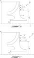
Fig. 4 is a cross-sectional view of an impeller in accordance with one embodiment for the gas turbine engine ofFig. 1 ; -
Fig. 5 is an enlarged view of a portion ofFig. 4 ; -
Fig. 6 is a cross-sectional view of an impeller in accordance with another embodiment for the gas turbine engine ofFig. 1 ; and -
Fig. 7 is a cross-sectional view of an impeller in accordance with another embodiment for the gas turbine engine ofFig. 1 . -
Fig. 1 illustrates an aircraft engine depicted as agas turbine engine 10 of a type preferably provided for use in subsonic flight, generally comprising in serial flow communication afan 12 through which ambient air is propelled, acompressor section 14 for pressurizing the air, acombustor 16 in which the compressed air is mixed with fuel and ignited for generating an annular stream of hot combustion gases, and aturbine section 18 for extracting energy from the combustion gases. Thefan 12, thecompressor section 14, and theturbine section 18 are rotatable about acentral axis 11 of thegas turbine engine 10. In the embodiment shown, thegas turbine engine 10 comprises a high-pressure spool having a high-pressure shaft 20 drivingly engaging a high-pressure turbine 18A of theturbine section 18 to a high-pressure compressor 14A of thecompressor section 14, and a low-pressure spool having a low-pressure shaft 21 drivingly engaging a low-pressure turbine 18B of the turbine section to a low-pressure compressor 14B of thecompressor section 14 and drivingly engaged to thefan 12. It will be understood that the contents of the present disclosure may be applicable to any suitable engines, such as turboprops and turboshafts, and reciprocating engines, such as piston and rotary engines without departing from the scope of the present disclosure. - Referring to
Figs. 2-3 , in the embodiment shown, thecompressor section 14, more specifically the high-pressure compressor 14A, includes an impeller I. The impeller I is rotatable about thecentral axis 11 for pressurizing air. The impeller I has a back face including three zones A, B, C disposed radially inward one another; zone C being the closest to thecentral axis 11. Depending on the location, stresses imparted on the impeller I as a result of its rotation about thecentral axis 11 vary from being dominant in a circumferential direction or in a radial direction. - Following prolonged utilization, a fatigue crack may form on a hub of the impeller I. Damage tolerance methods and tools can be used to determine the remaining crack propagation life and trajectory of the crack leading up to the need to replace the impeller I. Depending of where a crack initiates, it may affect the way said crack propagates. For instance, at higher and lower radii, such as within zones A and C, the dominant low-cycle fatigue stress is along a circumferential direction relative to the central axis 11 (i.e., hoop dominated). At a mid-radius location, such as within zone B, the dominant low-cycle fatigue stress is along a radial direction relative to the
central axis 11. Length of arrows presented inFig. 3 are indicative of which component of the stress is greater. InFig. 3 , σH denotes the hoop stress whereas σR denotes the radial stress. During the transition of stress from being radially dominated to hoop dominated, there is a location where the bi-axiality (ratio of hoop stress to radial stress) is equal to one. This may occur between zones A and B and between zones B and C. At these locations where the bi-axiality is equal to or proximate to one, cracks may theoretically initiate at any angle. If a crack initiates on the disc profile of a compressor, the resulting trajectory of the crack is a function of the initial crack orientation, and the resulting dominant LCF stress field. - When a crack initiates from a hoop dominated stress field (e.g., zones A or C) or where a bi-axiality ratio of one, the crack can initiate either in the radial direction, or at an angle. If a crack initiates at an angle and it is left to propagate, it may continue to grow at the same angle it initiated until it enters a unique stress field where both ends of the crack are dominated by hoop loading. This may result in the crack to turn on opposite ends in radially opposite directions.
- When a crack initiates from a radially dominated stress field (e.g., zone B), this crack will likely be perpendicular to the radial load. When left to propagate, this crack may continue to grow perpendicular to the radial load until it enters a higher radius, where hoop loading begins to dominate. In this case, the hoop loading turns the crack such that both ends of the crack propagate radially outwardly toward a gaspath-facing surface of the impeller. For safety reasons, it is preferred to have a crack that propagate perpendicularly to the radial load and grow toward the gaspath-facing surface, instead of growing toward the bore.
- Regardless of stress state, should a crack initiate in a radial direction, the radial load may never contribute to the growth of the crack. In some cases, only the hoop load may drive the growth of the crack toward the bore.
- The present disclosure proposes a rotor presenting crack mitigators, which may be in the form of bumps or grooves, that are used to reduce risks of cracks growing towards a bore of the rotor. In some embodiments, the crack mitigators may introduce a stress concentration factor in a radial flow stress direction as well as increase the local nominal stress. This may help to maximise the radial contribution of crack growth. These crack mitigators may increase a size of an area on the impeller I where a crack would grow toward the gaspath-facing surface, instead of growing toward the bore. These crack mitigators may be used for compressor rotors where the resulting disc stresses may be low and the corresponding low cycle fatigue life may be high. The crack mitigators may be designed to avoid altering the minimum life of the rotor while minimizing risks of cracks propagating towards the bore.
- Referring now to
Fig. 4 , an impeller forgas turbine engine 10 ofFig. 1 is shown at 30. Theimpeller 30 may be part of the high-pressure compressor 14A. It will be appreciated that the principles of the present disclosure may apply to any rotor such as, for instance, a compressor rotor of an axial compressor, an impeller of a turbine section, a turbine rotor of an axial turbine, and so on. - The
impeller 30 has ahub 31 that extends circumferential about thecentral axis 11 of thegas turbine engine 10. Thehub 31 has abore 32 and a gaspath-facingsurface 33 located radially outwardly of thebore 32 relative to thecentral axis 11. Thehub 31 includes afront face 34 that extends from thebore 32 to the gaspath-facingsurface 33. Thehub 31 includes aback face 35 that extends from thebore 32 to the gaspath-facingsurface 33. Theimpeller 30 includesblades 36 that are circumferentially distributed about thecentral axis 11. Theblades 36 protrude from the gaspath-facingsurface 33 of thehub 31. In the embodiment shown, theimpeller 30 has an inlet 30I that is oriented substantially axially relative to thecentral axis 11 and an outlet 30O that is oriented substantially radially relative to thecentral axis 11. Hence, theblades 36 and flow paths defined between each two adjacent ones of theblades 36 curve from a substantially axial orientation to a substantially radial orientation relative to thecentral axis 11. - The
impeller 30 may include one or more crack mitigator 40 that are use to at least partially alleviate effects of cracks on thehub 31 of theimpeller 30. In the embodiment shown, the crack mitigators 40 aregrooves 41 located on theback face 35 of thehub 31. It will be appreciated that the crack mitigators 40 may be located at any suitable locations on thehub 31. For instance, the crack mitigators may be located on one or more of a front face and a back face of a disc of a rotor of an axial compressor or turbine. - The
grooves 41 extend circumferentially about thecentral axis 11. Although threegrooves 41 are shown inFig. 4 , thehub 31 may alternatively include one, two, or more than three grooves without departing from the scope of the present disclosure. Thegrooves 41 are radially offset from one another. Thegrooves 41 may be radially spaced apart from one another. Any suitable number of grooves is contemplated. Thegrooves 41 may extend continuously around a full circumference about thecentral axis 11. Thegrooves 41 may extend circumferentially about a portion of the circumference (i.e., circumferentially discontinuous). For instance, each of thegrooves 41 may include a plurality of groove segments circumferentially distributed about thecentral axis 11; each of the groove segments extending circumferentially along a portion of the circumference of thehub 31. - Referring to
Figs. 4-5 , thegrooves 41 extend from a baseline surface S of theback face 35 of thehub 31. The baseline surface S is shown with a dashed line inFig. 5 and is defined by an imaginary surface extending across thegrooves 41 and connecting the surfaces of theback face 35 that are adjacent to and surrounding thegrooves 41, as shown. In the present embodiment, thegrooves 41 extend from the baseline surface S towards thefront face 34 in a direction having an axial component relative to thecentral axis 11. In other words, thegrooves 41 extend within a body of thehub 31. Material may therefore be removed form thehub 31 to create thegrooves 41. It will be appreciated that break edge (e.g., fillets) may be present at intersections between thegrooves 41 and the baseline surface S. These break edges may be from 0.003 inch to 0.015 inch in radius. Corner fillets may be of 0.005 inch to 0.020 inch in radius. - As shown in
Fig. 4 , the crack mitigators 40 may be located radially outwardly of a mid-plane of theback face 35. The mid-plane is located halfway between thebore 32 and a radially outward-most location of the gaspath-facingsurface 33. In the present case, the radially outward-most location of the gaspath-facingsurface 33 is located at the outlet 30O of theimpeller 30. In other words, the mid-plane may be located at a radial distance Rg from thecentral axis 11. The radial distance Rg corresponds to half of a first radial distance R1 from thecentral axis 11 to the radially outward-most location of the gaspath-facingsurface 33 plus half of a second radial distance R2 from thecentral axis 11 to thebore 32. - As shown more particularly on
Fig. 5 , thegroove 41 has a depth D1 extending in the axial direction and a height H1 extending in a radial direction relative to thecentral axis 11. A ratio of the depth D1 to the height H1 may range from 0.01 to 0.5. A ratio of a distance S12 between twoadjacent grooves 41 to a sum of heights H1, H2 of the two adjacent grooves may range from 0.1 to 5, in some cases from 0.25 to 5. The heights H1, H2 may extend in the radial direction relative to thecentral axis 11. - Referring now to
Fig. 6 , another embodiment of an impeller is shown at 130. For the sake of conciseness, only features differing from theimpeller 30 described above with reference toFigs. 4-5 are described below. - In the embodiment shown, the
impeller 130 has crack mitigators 40 provided in the form ofbumps 42. It will be appreciated that the crack mitigators 40 may be located at any suitable locations on thehub 31. For instance, the crack mitigators may be located on one or more of a front face and a back face of a disc of a rotor of an axial compressor or turbine. - The
bumps 42 extend circumferentially about thecentral axis 11. Although threebumps 42 are shown inFig. 4 , thehub 31 may alternatively include one, two, or more than three bumps without departing from the scope of the present disclosure. Thebumps 42 are radially offset from one another. Thebumps 42 may be radially spaced apart from one another. Any suitable number of bumps is contemplated. Thebumps 42 may extend continuously around a full circumference about thecentral axis 11. Thebumps 42 may extend circumferentially about a portion of the circumference (i.e., circumferentially discontinuous). For instance, each of thebumps 42 may include a plurality of bump segments circumferentially distributed about thecentral axis 11; each of the bump segments extending circumferentially along a portion of the circumference of thehub 31. - The
bumps 42 extend from the baseline surface S of theback face 35 of thehub 31. In this embodiment, the baseline surface S is defined by an imaginary surface extending through thebumps 42 and connecting the surfaces of theback face 35 that are adjacent to and surrounding thebumps 42. In the present embodiment, thebumps 42 extend from the baseline surface S away from thefront face 34 and away from theback face 35 in the direction having the axial component relative to thecentral axis 11. In other words, thebumps 42 protrude from a body of thehub 31. Material may therefore be added to thehub 31 to create thebumps 42. Intersections between the baseline surface S and thebumps 42 may be smooth. In other words, fillets may be present at those intersections. - As for the
grooves 41, thebumps 42 may be located radially outwardly of the mid-plane of theback face 35. Thebumps 42 may have the same dimensions of thegrooves 41. That is, thebumps 42 may have a depth D1 extending in the axial direction and a height H1 extending in a radial direction relative to thecentral axis 11. A ratio of the depth D1 to the height H1 may range from 0.01 to 0.5. A ratio of a distance S12 between twoadjacent bumps 42 to a sum of heights H1, H2 of the twoadjacent bumps 42 may range from 0.1 to 0.5, in some cases from 0.25 to 5. The heights H1, H2 may extend in the radial direction relative to thecentral axis 11. - Referring now to
Fig. 7 , another embodiment of an impeller is shown at 230. For the sake of conciseness, only features differing from theimpeller 30 described above with reference toFigs. 4-5 are described below. - In the embodiment shown, the
impeller 230 includes crack mitigators, which are provided here as a combination ofgrooves 41 and bumps 42. Thegrooves 41 may be effective at directing a crack whereas thebumps 42 may be effective at slowing down crack propagation. Consequently, a combination of bump(s) 42 and groove(s) 41 may redirect new cracks in the circumferential direction and slow down propagation of cracks that tend to propagate towards thebore 32. - In the embodiment shown, the
impeller 230 includes at least onegrooves 41 as described above with reference toFigs. 4-5 and at least one bump as described above with reference toFigs. 6 . Thebump 42 may be located radially outwardly of thegroove 41. - Referring to
Figs. 4-7 , thegrooves 41 and thebumps 42 may have any suitable profile. For instance, thegrooves 41 and thebumps 42 are shown as having an arc shaped profile (e.g., semi-circular) inFigs. 4 to 7 . Alternatively, thegrooves 41 and thebumps 42 may have a profile having a rectangular, elliptical, or any other suitable shapes. Fillets may be used to join thegrooves 41 and thebumps 42 to the baseline surface S of theback face 35 of thehub 31 of theimpeller 30. Thegrooves 41 and thebumps 42 may have a width that may vary in a circumferential direction relative to thecentral axis 11. Thegrooves 41 and thebumps 42 may have a height that may vary in the circumferential direction. In other words, the height and/or the width may be nonuniform. - It will be appreciated that the crack mitigator as defined herein may include any of the following, in any combination: a protrusion, a projection, a stiffener, a tab, a flange, a pin, a cavity, an aperture, and a recess. All such structures are understood to constitute a structure that mitigates cracks and forms a crack mitigator as defined herein.
- The embodiments described in this document provide non-limiting examples of possible implementations of the present technology. Upon review of the present disclosure, a person of ordinary skill in the art will recognize that changes may be made to the embodiments described herein without departing from the scope of the present technology. Yet further modifications could be implemented by a person of ordinary skill in the art in view of the present disclosure, which modifications would be within the scope of the present technology.
Claims (15)
- A rotor (30; 130; 230) for an aircraft engine (10), the rotor (30 ... 230) comprising:a hub (31) extending circumferentially about a central axis (11), the hub (31) having a bore (32), a gaspath-facing surface (33) located radially outwardly of the bore (32) relative to the central axis (11), a first face (35) extending from the bore (32) to the gaspath-facing surface (33), and a second face (34) opposite the first face (35) and extending from the bore (32) to the gaspath-facing surface (33);blades (36) circumferentially distributed about the central axis (11), the blades (36) protruding away from the gaspath-facing surface (33) of the hub (31); anda crack mitigator (40) located on the first face (35), the crack mitigator (40) extending circumferentially relative to the central axis (11) and axially from a baseline surface (S) of the first face (35).
- The rotor (30; 130; 230) of claim 1, wherein the crack mitigator (40) is located radially outwardly of a mid-plane of the first face (35), the mid-plane located halfway between the bore (32) and a radially outward-most location of the gaspath-facing surface (33).
- The rotor (30) of claim 1 or 2, wherein the crack mitigator (40) includes at least one groove (41) extending in an axial direction relative to the central axis (11) from the baseline surface (S) of the first face (35).
- The rotor (30) of claim 3, wherein the at least one groove (41) has a depth (D1) extending in the axial direction and a height (H1) extending in a radial direction relative to the central axis (11), a ratio of the depth (D1) to the height (H1) ranging from 0.01 to 0.5.
- The rotor (30) of claim 3 or 4, wherein the at least one groove (41) includes at least two grooves (41) radially offset from one another.
- The rotor (30) of claim 5, wherein a ratio of a distance (S12) between the at least two grooves (41) to a sum of heights (H1, H2) of the at least two grooves (41) ranges from 0.25 to 5, the heights extending in a radial direction relative to the central axis (11).
- The rotor (130) of claim 1 or 2, wherein the crack mitigator (40) includes at least one bump (42) extending in an axial direction relative to the central axis (11) from the baseline surface (S) of the first face (35).
- The rotor (130) of claim 7, wherein the at least one bump (42) has a depth (D1) extending in the axial direction and a height (H1) extending in a radial direction relative to the central axis (11), a ratio of the depth (D1) to the height (H1) ranging from 0.01 to 0.5.
- The rotor (130) of claim 7 or 8, wherein the at least one bump (42) includes at least two bumps (42) radially offset from one another.
- The rotor (130) of claim 9, wherein a ratio of a distance (S12) between the at least two bumps (42) to a sum of heights (H1, H2) of the at least two bumps (42) ranges from 0.25 to 5, the heights extending in a radial direction relative to the central axis (11).
- The rotor (230) of any preceding claim, wherein the crack mitigator (40) includes at least one bump (42) and at least one groove (41).
- The rotor (230) of claim 11, wherein the at least one bump (42) is located radially outwardly of the at least one groove (41).
- A compressor section (14) of an aircraft engine (10), the compressor section (14) having an impeller rotatable about a central axis (11), the impeller comprising the rotor (30; 130; 230) as defined in any preceding claim.
- The compressor section (14) of claim 13, wherein the crack mitigator (40) is a first crack mitigator (40), a second crack mitigator (40) radially offset from the first crack mitigator (40), a ratio of a distance (S12) between the first crack mitigator (40) and the second crack mitigator (40) to a sum of heights (H1, H2) of the first crack mitigator (40) and the second crack mitigator (40) ranging from 0.25 to 5, the heights extending in a radial direction relative to the central axis (11).
- The compressor section (14) of claim 13 or 14, wherein the crack mitigator (40) is a first crack mitigator (40), a second crack mitigator (40) radially offset from the first crack mitigator (40), and wherein:the first crack mitigator (40) being a bump (42), the second crack mitigator (40) being a groove (41), the bump (42) located radially outwardly of the groove (41);the first crack mitigator (40) being a bump (42), the second crack mitigator (40) being a bump (42); orthe first crack mitigator (40) being a groove (41), the second crack mitigator (40) being a groove (41).
Applications Claiming Priority (1)
| Application Number | Priority Date | Filing Date | Title |
|---|---|---|---|
| US17/658,461 US11795821B1 (en) | 2022-04-08 | 2022-04-08 | Rotor having crack mitigator |
Publications (1)
| Publication Number | Publication Date |
|---|---|
| EP4257805A1 true EP4257805A1 (en) | 2023-10-11 |
Family
ID=85980584
Family Applications (1)
| Application Number | Title | Priority Date | Filing Date |
|---|---|---|---|
| EP23167152.0A Pending EP4257805A1 (en) | 2022-04-08 | 2023-04-06 | Rotor for an aircraft engine and compressor section of an aircraft engine |
Country Status (3)
| Country | Link |
|---|---|
| US (1) | US11795821B1 (en) |
| EP (1) | EP4257805A1 (en) |
| CA (1) | CA3193908A1 (en) |
Citations (3)
| Publication number | Priority date | Publication date | Assignee | Title |
|---|---|---|---|---|
| EP2916010A1 (en) * | 2012-10-30 | 2015-09-09 | Mitsubishi Heavy Industries, Ltd. | Impeller, and rotating machine provided with same |
| US20170030206A1 (en) * | 2015-07-29 | 2017-02-02 | Korea Maritime University Industry-Academic Cooperation Foundation | Apparatus for Decreasing Thrust of Radial Inflow Turbine |
| US20170037864A1 (en) * | 2015-08-04 | 2017-02-09 | Bosch Mahle Turbo Systems Gmbh & Co. Kg | Compressor wheel of a charging device |
Family Cites Families (7)
| Publication number | Priority date | Publication date | Assignee | Title |
|---|---|---|---|---|
| US6749400B2 (en) | 2002-08-29 | 2004-06-15 | General Electric Company | Gas turbine engine disk rim with axially cutback and circumferentially skewed cooling air slots |
| JP4554189B2 (en) * | 2003-11-26 | 2010-09-29 | 株式会社エンプラス | Centrifugal impeller |
| JP5439112B2 (en) * | 2009-10-07 | 2014-03-12 | 三菱重工業株式会社 | Turbine blade |
| FR2975733B1 (en) * | 2011-05-23 | 2015-12-18 | Turbomeca | CENTRIFUGAL COMPRESSOR WHEEL |
| US8936439B2 (en) * | 2011-07-11 | 2015-01-20 | Hamilton Sundstrand Corporation | Radial turbine backface curvature stress reduction |
| CN104903561B (en) | 2013-02-22 | 2018-06-19 | 三菱重工业株式会社 | Turbine rotor and the turbocharger for being incorporated with the turbine rotor |
| US9714577B2 (en) | 2013-10-24 | 2017-07-25 | Honeywell International Inc. | Gas turbine engine rotors including intra-hub stress relief features and methods for the manufacture thereof |
-
2022
- 2022-04-08 US US17/658,461 patent/US11795821B1/en active Active
-
2023
- 2023-03-22 CA CA3193908A patent/CA3193908A1/en active Pending
- 2023-04-06 EP EP23167152.0A patent/EP4257805A1/en active Pending
Patent Citations (3)
| Publication number | Priority date | Publication date | Assignee | Title |
|---|---|---|---|---|
| EP2916010A1 (en) * | 2012-10-30 | 2015-09-09 | Mitsubishi Heavy Industries, Ltd. | Impeller, and rotating machine provided with same |
| US20170030206A1 (en) * | 2015-07-29 | 2017-02-02 | Korea Maritime University Industry-Academic Cooperation Foundation | Apparatus for Decreasing Thrust of Radial Inflow Turbine |
| US20170037864A1 (en) * | 2015-08-04 | 2017-02-09 | Bosch Mahle Turbo Systems Gmbh & Co. Kg | Compressor wheel of a charging device |
Also Published As
| Publication number | Publication date |
|---|---|
| CA3193908A1 (en) | 2023-10-08 |
| US11795821B1 (en) | 2023-10-24 |
| US20230323775A1 (en) | 2023-10-12 |
Similar Documents
| Publication | Publication Date | Title |
|---|---|---|
| US9874101B2 (en) | Platform with curved edges | |
| US9353629B2 (en) | Turbine blade apparatus | |
| US20120272663A1 (en) | Centrifugal compressor assembly with stator vane row | |
| JP6557478B2 (en) | Turbine bucket and method for balancing turbine bucket tip shroud | |
| US11346367B2 (en) | Compressor rotor casing with swept grooves | |
| RU2667853C2 (en) | Turbine blade with pin seal slot | |
| EP4130430A1 (en) | Integrated bladed rotor | |
| US9856740B2 (en) | Tip-controlled integrally bladed rotor for gas turbine engine | |
| JP7150534B2 (en) | 1st stage stator vane of gas turbine and gas turbine | |
| JP2016510854A (en) | Hot streak alignment method for gas turbine durability | |
| EP4257805A1 (en) | Rotor for an aircraft engine and compressor section of an aircraft engine | |
| US20190309630A1 (en) | Turbine vane having improved flexibility | |
| EP4047188A1 (en) | Housing for a centrifugal compressor | |
| US9970452B2 (en) | Forward-swept impellers and gas turbine engines employing the same | |
| EP3927947B1 (en) | Nozzle ring for a radial turbine and exhaust gas turbocharger including the same | |
| US10962021B2 (en) | Non-axisymmetric impeller hub flowpath | |
| US20210156261A1 (en) | Turbomachine nozzle with an airfoil having a curvilinear trailing edge | |
| US11299992B2 (en) | Rotor blade damping structures | |
| US20230392503A1 (en) | Airfoil ribs for rotor blades | |
| US20230073422A1 (en) | Stator with depressions in gaspath wall adjacent trailing edges | |
| US11629722B2 (en) | Impeller shroud frequency tuning rib | |
| KR101937579B1 (en) | Turbine disc, turbine and gas turbine comprising the same |
Legal Events
| Date | Code | Title | Description |
|---|---|---|---|
| PUAI | Public reference made under article 153(3) epc to a published international application that has entered the european phase |
Free format text: ORIGINAL CODE: 0009012 |
|
| STAA | Information on the status of an ep patent application or granted ep patent |
Free format text: STATUS: THE APPLICATION HAS BEEN PUBLISHED |
|
| AK | Designated contracting states |
Kind code of ref document: A1 Designated state(s): AL AT BE BG CH CY CZ DE DK EE ES FI FR GB GR HR HU IE IS IT LI LT LU LV MC ME MK MT NL NO PL PT RO RS SE SI SK SM TR |
|
| STAA | Information on the status of an ep patent application or granted ep patent |
Free format text: STATUS: REQUEST FOR EXAMINATION WAS MADE |