EP4257783B1 - Door opener with a monitoring system - Google Patents
Door opener with a monitoring system Download PDFInfo
- Publication number
- EP4257783B1 EP4257783B1 EP22382337.8A EP22382337A EP4257783B1 EP 4257783 B1 EP4257783 B1 EP 4257783B1 EP 22382337 A EP22382337 A EP 22382337A EP 4257783 B1 EP4257783 B1 EP 4257783B1
- Authority
- EP
- European Patent Office
- Prior art keywords
- cam
- front part
- door
- bolt
- stop
- Prior art date
- Legal status (The legal status is an assumption and is not a legal conclusion. Google has not performed a legal analysis and makes no representation as to the accuracy of the status listed.)
- Active
Links
Images


Classifications
-
- E—FIXED CONSTRUCTIONS
- E05—LOCKS; KEYS; WINDOW OR DOOR FITTINGS; SAFES
- E05B—LOCKS; ACCESSORIES THEREFOR; HANDCUFFS
- E05B47/00—Operating or controlling locks or other fastening devices by electric or magnetic means
- E05B47/0046—Electric or magnetic means in the striker or on the frame; Operating or controlling the striker plate
- E05B47/0047—Striker rotating about an axis parallel to the wing edge
-
- E—FIXED CONSTRUCTIONS
- E05—LOCKS; KEYS; WINDOW OR DOOR FITTINGS; SAFES
- E05B—LOCKS; ACCESSORIES THEREFOR; HANDCUFFS
- E05B15/00—Other details of locks; Parts for engagement by bolts of fastening devices
- E05B15/02—Striking-plates; Keepers; Bolt staples; Escutcheons
- E05B15/0205—Striking-plates, keepers, staples
- E05B15/024—Striking-plates, keepers, staples adjustable
-
- E—FIXED CONSTRUCTIONS
- E05—LOCKS; KEYS; WINDOW OR DOOR FITTINGS; SAFES
- E05B—LOCKS; ACCESSORIES THEREFOR; HANDCUFFS
- E05B47/00—Operating or controlling locks or other fastening devices by electric or magnetic means
- E05B2047/0048—Circuits, feeding, monitoring
- E05B2047/0067—Monitoring
- E05B2047/0068—Door closed
Definitions
- the present invention relates to a door opener with a monitoring system, suitable for locking and unlocking a door and providing a signal indicating the state of the door.
- This invention falls within the sector of closing devices with access control for doors, windows and closures in general.
- Electric and electronic door openers are access control devices which allow locking/unlocking a door.
- Said door openers are assembled in the frame of the door and have a retaining bolt for the catch of the lock of the door in the closed position.
- Said door openers have an internal mechanism that is locked or unlocked by means of the activation or deactivation of a solenoid. In an unlocked position, the internal mechanism allows a rotational movement of the bolt, and it allows the catch of the door to slide over said bolt when opening the door.
- the bolt of the door opener generally has a height adjustable front part and is provided with a closing stop in charge of preventing the movement of the catch and the rotation of the door towards the open position when the internal mechanism keeps the bolt of the door opener locked.
- Electric or electronic door openers having a monitored function are able to send a signal to an access control system, indicating the open or closed state of the door at all times.
- Monitored door openers today have a drive cam assembled with the possibility of rotation in the casing of the door opener and arranged in front of the front part of the bolt. Said cam is operated by the latch of the door and when said door reaches the closed position, the drive cam acts by means of an arm on a microswitch of the monitoring system, providing a signal indicating that the door is closed.
- Each one of documents DE102004037827A1 , DE102014104094A1 , EP3599328A1 , and ES1070806U discloses a door opener having, in essence, a bolt comprised of a bolt base mounted to pivot about a rotating shaft and a front part that is adjustable in height with respect to the bolt base between a lower position and an upper position away from the rotating shaft.
- the adjustable front part comprises a stop defining a lower plane for retaining a catch of a door in a closed position.
- the door opener further comprises an internal mechanism for locking and unlocking the bolt, a monitoring system for monitoring the state of the door, and a drive cam that is located facing the front part of the bolt and that is moved by the catch of the door from an inoperative position to an operative position in which the cam drives the monitoring system.
- a groove configured to receive the cam is defined both on a front face and in the stop of the front part.
- the monitored door opener object of the invention is of the type described in the preamble of the main claim, comprising: a bolt assembled on a rotating shaft; a height adjustable front part with respect to the bolt and provided with a stop defining a lower plane for retaining a catch of a door in a closed position; an internal mechanism for locking and unlocking the bolt, activating a solenoid, and a drive cam of a monitoring system for monitoring the state of the door, facing the front part of the bolt, and said cam being moved by the catch of the door from an inoperative position to an operative position in which said cam drives the monitoring system by providing a signal about the closed state of the door.
- This door opener has certain technical features which ensure the effective contact of the catch of the door with the drive cam of the monitoring system for monitoring the state of the door, in all the height regulation positions of the front part of the bolt and without reducing the useful space for engagement of the catch with the bolt of the door opener.
- the adjustable front part of the door opener comprises a receiving groove of the cam, said groove being defined on the front face and in the stop of said adjustable front part.
- the cam and the front part are sized such that said front part is movable between a lower position in which the end of the cam is arranged inside the groove of the stop of the adjustable front part, and an upper position away from the rotating shaft of the bolt, in which the end of the cam is arranged considerably flush with the lower plane of the stop of the bolt or inside the groove of said stop.
- This feature allows, in the upper and most unfavourable position of the adjustable front part, no empty space to be left between the cam activating the microswitch and the stop of the adjustable front part locking the catch of the door, whereby ensuring that no errors occur in the activation of the monitoring system and that the catch of the door is not engaged with the cam, causing it to deform or break.
- said groove has on the front face of the adjustable front part a depth equal to or greater than the thickness of the cam, such that when said cam is operated by the catch of the door, it is housed in the groove of the front part and does not reduce the length defined in the lower plane of the stop of the front part for engaging and locking the catch of the door; which entails an advantage with respect to door openers existing today, in which the cam activating the microswitch is kept in a projecting position with respect to the surface of the adjustable front part when it is operated by the catch of the door, said cam reducing the useful space defined in the adjustable front part for locking the catch of the door.
- the cam can be formed by a one-piece body having a length sufficient for the end thereof to be housed in the groove of the stop of the adjustable front part when said front part is in the upper, most unfavourable position; or it may comprise fixing means for fixing a supplement, which increases its length and forms the end of the cam intended for being housed in the groove of the stop of the adjustable front part, preventing a free space from being left between the stop of the adjustable front part and the end of the cam.
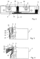
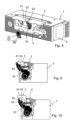
- Figures 1 to 7 represent a door opener (1) provided with a bolt (2) with a rotating shaft (21) and having a height adjustable front part (3) between a lower position represented in Figures 1 to 4 and an upper position represented in Figures 5 to 7 , and fixed to the bolt (2) by means of screws (4).
- the mentioned front part (3) has in its front-upper area a stop (31) defining a lower plane (32) for retaining the catch (C) of the lock of a door when said door reaches a closed position, as shown in Figures 4 and 7 .
- the door opener (1) has an internal mechanism (not represented) for locking and unlocking the bolt (2), which can be driven by means of a solenoid, and a drive cam (51) of a monitoring system (5) for monitoring the state of the door, facing the front part (3) of the bolt (2).
- the cam (51), formed in this exemplary embodiment by a one-piece body, is moved by the catch (C) of the door from an inoperative position represented in Figures 3 and 6 , to an operative position represented in Figures 4 and 7 when said door reaches the closed position.
- the adjustable front part (3) of the bolt has a groove 33 affecting both the front face and the stop (31) of said adjustable front part (3).
- Both the cam (51) and the front part (3) are sized such that said front part (3) is movable between: a lower position, shown in Figures 3 and 4 , in which the end of the cam (51) is arranged inside the groove (33) of the stop (31), and an upper position in which the end of the cam is kept inside the groove (33) of the stop (31) or considerably flush with the lower plane (32) of the mentioned stop (31), as shown in Figures 6 and 7 .
- the sizing of the cam (51) and of the front part (3) of the bolt (2) prevent a space from being defined between the lower plane (32) of the stop (31) of the bolt and the end of the cam (51), in which the end of the catch (C) can be introduced without moving the cam (51) towards the operative position, causing a failure in the monitoring system for monitoring the state of the door.
- the groove (33) has on the front face of the front part (3) a depth equal to or greater than the thickness of the cam (51), such that in the operative position the cam (51) is arranged inside the mentioned groove (33) as shown in Figures 4 and 7 .
- the cam (51) therefore does not project from the front surface of the front part (3) and does not reduce the length (L) defined in the lower plane (32) of the adjustable stop (31) for supporting and retaining the catch (C) in the closed position of the door.
- the cam (51) comprises a supplement (52) fixed to the body of the cam (51) by fixing means (53) represented by a screw, said supplement (52) forming the end of the cam (51) intended for being housed in the groove (33) of the front part (3) of the bolt (2).
Landscapes
- Lock And Its Accessories (AREA)
- Auxiliary Devices For Machine Tools (AREA)
- Power-Operated Mechanisms For Wings (AREA)
Priority Applications (3)
| Application Number | Priority Date | Filing Date | Title |
|---|---|---|---|
| ES22382337T ES2995184T3 (en) | 2022-04-07 | 2022-04-07 | Door opener with a monitoring system |
| EP22382337.8A EP4257783B1 (en) | 2022-04-07 | 2022-04-07 | Door opener with a monitoring system |
| PL22382337.8T PL4257783T3 (pl) | 2022-04-07 | 2022-04-07 | Urządzenie do otwierania drzwi z układem monitorowania |
Applications Claiming Priority (1)
| Application Number | Priority Date | Filing Date | Title |
|---|---|---|---|
| EP22382337.8A EP4257783B1 (en) | 2022-04-07 | 2022-04-07 | Door opener with a monitoring system |
Publications (3)
| Publication Number | Publication Date |
|---|---|
| EP4257783A1 EP4257783A1 (en) | 2023-10-11 |
| EP4257783C0 EP4257783C0 (en) | 2024-08-21 |
| EP4257783B1 true EP4257783B1 (en) | 2024-08-21 |
Family
ID=81392899
Family Applications (1)
| Application Number | Title | Priority Date | Filing Date |
|---|---|---|---|
| EP22382337.8A Active EP4257783B1 (en) | 2022-04-07 | 2022-04-07 | Door opener with a monitoring system |
Country Status (3)
| Country | Link |
|---|---|
| EP (1) | EP4257783B1 (pl) |
| ES (1) | ES2995184T3 (pl) |
| PL (1) | PL4257783T3 (pl) |
Family Cites Families (4)
| Publication number | Priority date | Publication date | Assignee | Title |
|---|---|---|---|---|
| DE102004037827B4 (de) * | 2004-08-04 | 2007-01-11 | Assa Abloy Sicherheitstechnik Gmbh | Elektrischer Türöffner |
| ES1070806Y (es) * | 2009-05-22 | 2010-07-23 | Openers & Closers Sl | Abrepuertas electrico |
| DE102014104094B4 (de) * | 2014-03-25 | 2018-09-13 | Assa Abloy Sicherheitstechnik Gmbh | Türöffner mit Rückmeldekontakt |
| PL3599328T3 (pl) * | 2018-07-26 | 2021-03-08 | Openers & Closers, S.L. | Zamek antypaniczny do drzwi |
-
2022
- 2022-04-07 PL PL22382337.8T patent/PL4257783T3/pl unknown
- 2022-04-07 ES ES22382337T patent/ES2995184T3/es active Active
- 2022-04-07 EP EP22382337.8A patent/EP4257783B1/en active Active
Also Published As
| Publication number | Publication date |
|---|---|
| EP4257783C0 (en) | 2024-08-21 |
| PL4257783T3 (pl) | 2024-10-21 |
| ES2995184T3 (en) | 2025-02-07 |
| EP4257783A1 (en) | 2023-10-11 |
Similar Documents
| Publication | Publication Date | Title |
|---|---|---|
| US6349576B2 (en) | Lockable sash assembly | |
| US5076625A (en) | Electric strike | |
| US7591157B2 (en) | Security lock arrangement | |
| US20080150300A1 (en) | Multipoint Lock Assembly | |
| US4679416A (en) | Trigger and latch bolt assembly | |
| EP1092827A2 (en) | Multi point bolting mechanism | |
| GB2313620A (en) | Multi-point locking assembly for a door or window | |
| US5881498A (en) | Tilt and turn window lock system | |
| GB2131078A (en) | Bolt retaining device | |
| WO2008014542A1 (en) | Lock mechanism | |
| US6151935A (en) | Deadbolt combination lock system with automatic locking spring bolt | |
| CN115735040B (zh) | 锁止设备 | |
| EP4257783A1 (en) | Door opener with a monitoring system | |
| HU223791B1 (hu) | Kétszárnyas ajtó, különösen tűzvédelmi ajtó | |
| CN110998046B (zh) | 用于关闭两个铰接元件的安全设备、开门器和包括所述设备的门 | |
| CA2401162A1 (en) | Closing sheet for escape doors | |
| EP4345234A1 (en) | Assembly for security locks and relative lock | |
| EP3743578B1 (en) | Electrical door strike functioning under pressure | |
| US2428063A (en) | Elevator door lock | |
| EP3702557B1 (en) | Counter lock for an inactive leaf of a double door | |
| EP3599328B1 (en) | Panic lock for doors | |
| EP3705668B1 (en) | Door locking device | |
| US5193862A (en) | Anti-theft latch mechanism especially suitable for vending machines | |
| EP3262257A1 (en) | Universal lock with sliding blocking mechanism | |
| WO2009060175A1 (en) | Locks for windows and doors |
Legal Events
| Date | Code | Title | Description |
|---|---|---|---|
| PUAI | Public reference made under article 153(3) epc to a published international application that has entered the european phase |
Free format text: ORIGINAL CODE: 0009012 |
|
| STAA | Information on the status of an ep patent application or granted ep patent |
Free format text: STATUS: THE APPLICATION HAS BEEN PUBLISHED |
|
| AK | Designated contracting states |
Kind code of ref document: A1 Designated state(s): AL AT BE BG CH CY CZ DE DK EE ES FI FR GB GR HR HU IE IS IT LI LT LU LV MC MK MT NL NO PL PT RO RS SE SI SK SM TR |
|
| STAA | Information on the status of an ep patent application or granted ep patent |
Free format text: STATUS: REQUEST FOR EXAMINATION WAS MADE |
|
| P01 | Opt-out of the competence of the unified patent court (upc) registered |
Effective date: 20231128 |
|
| 17P | Request for examination filed |
Effective date: 20231221 |
|
| GRAP | Despatch of communication of intention to grant a patent |
Free format text: ORIGINAL CODE: EPIDOSNIGR1 |
|
| STAA | Information on the status of an ep patent application or granted ep patent |
Free format text: STATUS: GRANT OF PATENT IS INTENDED |
|
| RIC1 | Information provided on ipc code assigned before grant |
Ipc: E05B 47/00 20060101ALI20240430BHEP Ipc: E05B 15/02 20060101AFI20240430BHEP |
|
| INTG | Intention to grant announced |
Effective date: 20240531 |
|
| GRAS | Grant fee paid |
Free format text: ORIGINAL CODE: EPIDOSNIGR3 |
|
| GRAA | (expected) grant |
Free format text: ORIGINAL CODE: 0009210 |
|
| STAA | Information on the status of an ep patent application or granted ep patent |
Free format text: STATUS: THE PATENT HAS BEEN GRANTED |
|
| AK | Designated contracting states |
Kind code of ref document: B1 Designated state(s): AL AT BE BG CH CY CZ DE DK EE ES FI FR GB GR HR HU IE IS IT LI LT LU LV MC MK MT NL NO PL PT RO RS SE SI SK SM TR |
|
| REG | Reference to a national code |
Ref country code: GB Ref legal event code: FG4D |
|
| REG | Reference to a national code |
Ref country code: CH Ref legal event code: EP |
|
| REG | Reference to a national code |
Ref country code: IE Ref legal event code: FG4D |
|
| REG | Reference to a national code |
Ref country code: DE Ref legal event code: R096 Ref document number: 602022005503 Country of ref document: DE |
|
| U01 | Request for unitary effect filed |
Effective date: 20240909 |
|
| U07 | Unitary effect registered |
Designated state(s): AT BE BG DE DK EE FI FR IT LT LU LV MT NL PT RO SE SI Effective date: 20240924 |
|
| P04 | Withdrawal of opt-out of the competence of the unified patent court (upc) registered |
Free format text: CASE NUMBER: APP_52719/2024 Effective date: 20240919 |
|
| P05 | Withdrawal of opt-out of the competence of the unified patent court (upc) changed |
Free format text: CASE NUMBER: APP_52719/2024 Effective date: 20240924 |
|
| PG25 | Lapsed in a contracting state [announced via postgrant information from national office to epo] |
Ref country code: NO Free format text: LAPSE BECAUSE OF FAILURE TO SUBMIT A TRANSLATION OF THE DESCRIPTION OR TO PAY THE FEE WITHIN THE PRESCRIBED TIME-LIMIT Effective date: 20241121 |
|
| PG25 | Lapsed in a contracting state [announced via postgrant information from national office to epo] |
Ref country code: GR Free format text: LAPSE BECAUSE OF FAILURE TO SUBMIT A TRANSLATION OF THE DESCRIPTION OR TO PAY THE FEE WITHIN THE PRESCRIBED TIME-LIMIT Effective date: 20241122 |
|
| PG25 | Lapsed in a contracting state [announced via postgrant information from national office to epo] |
Ref country code: IS Free format text: LAPSE BECAUSE OF FAILURE TO SUBMIT A TRANSLATION OF THE DESCRIPTION OR TO PAY THE FEE WITHIN THE PRESCRIBED TIME-LIMIT Effective date: 20241221 |
|
| PG25 | Lapsed in a contracting state [announced via postgrant information from national office to epo] |
Ref country code: HR Free format text: LAPSE BECAUSE OF FAILURE TO SUBMIT A TRANSLATION OF THE DESCRIPTION OR TO PAY THE FEE WITHIN THE PRESCRIBED TIME-LIMIT Effective date: 20240821 |
|
| PG25 | Lapsed in a contracting state [announced via postgrant information from national office to epo] |
Ref country code: RS Free format text: LAPSE BECAUSE OF FAILURE TO SUBMIT A TRANSLATION OF THE DESCRIPTION OR TO PAY THE FEE WITHIN THE PRESCRIBED TIME-LIMIT Effective date: 20241121 |
|
| PG25 | Lapsed in a contracting state [announced via postgrant information from national office to epo] |
Ref country code: RS Free format text: LAPSE BECAUSE OF FAILURE TO SUBMIT A TRANSLATION OF THE DESCRIPTION OR TO PAY THE FEE WITHIN THE PRESCRIBED TIME-LIMIT Effective date: 20241121 Ref country code: NO Free format text: LAPSE BECAUSE OF FAILURE TO SUBMIT A TRANSLATION OF THE DESCRIPTION OR TO PAY THE FEE WITHIN THE PRESCRIBED TIME-LIMIT Effective date: 20241121 Ref country code: IS Free format text: LAPSE BECAUSE OF FAILURE TO SUBMIT A TRANSLATION OF THE DESCRIPTION OR TO PAY THE FEE WITHIN THE PRESCRIBED TIME-LIMIT Effective date: 20241221 Ref country code: HR Free format text: LAPSE BECAUSE OF FAILURE TO SUBMIT A TRANSLATION OF THE DESCRIPTION OR TO PAY THE FEE WITHIN THE PRESCRIBED TIME-LIMIT Effective date: 20240821 Ref country code: GR Free format text: LAPSE BECAUSE OF FAILURE TO SUBMIT A TRANSLATION OF THE DESCRIPTION OR TO PAY THE FEE WITHIN THE PRESCRIBED TIME-LIMIT Effective date: 20241122 |
|
| REG | Reference to a national code |
Ref country code: ES Ref legal event code: FG2A Ref document number: 2995184 Country of ref document: ES Kind code of ref document: T3 Effective date: 20250207 |
|
| U20 | Renewal fee for the european patent with unitary effect paid |
Year of fee payment: 4 Effective date: 20250225 |
|
| PG25 | Lapsed in a contracting state [announced via postgrant information from national office to epo] |
Ref country code: SM Free format text: LAPSE BECAUSE OF FAILURE TO SUBMIT A TRANSLATION OF THE DESCRIPTION OR TO PAY THE FEE WITHIN THE PRESCRIBED TIME-LIMIT Effective date: 20240821 |
|
| PG25 | Lapsed in a contracting state [announced via postgrant information from national office to epo] |
Ref country code: CZ Free format text: LAPSE BECAUSE OF FAILURE TO SUBMIT A TRANSLATION OF THE DESCRIPTION OR TO PAY THE FEE WITHIN THE PRESCRIBED TIME-LIMIT Effective date: 20240821 |
|
| PG25 | Lapsed in a contracting state [announced via postgrant information from national office to epo] |
Ref country code: SK Free format text: LAPSE BECAUSE OF FAILURE TO SUBMIT A TRANSLATION OF THE DESCRIPTION OR TO PAY THE FEE WITHIN THE PRESCRIBED TIME-LIMIT Effective date: 20240821 |
|
| PLBE | No opposition filed within time limit |
Free format text: ORIGINAL CODE: 0009261 |
|
| STAA | Information on the status of an ep patent application or granted ep patent |
Free format text: STATUS: NO OPPOSITION FILED WITHIN TIME LIMIT |
|
| PGFP | Annual fee paid to national office [announced via postgrant information from national office to epo] |
Ref country code: ES Payment date: 20250502 Year of fee payment: 4 |
|
| PGFP | Annual fee paid to national office [announced via postgrant information from national office to epo] |
Ref country code: CH Payment date: 20250501 Year of fee payment: 4 |
|
| 26N | No opposition filed |
Effective date: 20250522 |
|
| PG25 | Lapsed in a contracting state [announced via postgrant information from national office to epo] |
Ref country code: MC Free format text: LAPSE BECAUSE OF FAILURE TO SUBMIT A TRANSLATION OF THE DESCRIPTION OR TO PAY THE FEE WITHIN THE PRESCRIBED TIME-LIMIT Effective date: 20240821 |
|
| PG25 | Lapsed in a contracting state [announced via postgrant information from national office to epo] |
Ref country code: IE Free format text: LAPSE BECAUSE OF NON-PAYMENT OF DUE FEES Effective date: 20250407 |
|
| PGFP | Annual fee paid to national office [announced via postgrant information from national office to epo] |
Ref country code: TR Payment date: 20260325 Year of fee payment: 5 |
|
| U20 | Renewal fee for the european patent with unitary effect paid |
Year of fee payment: 5 Effective date: 20260318 |
|
| PGFP | Annual fee paid to national office [announced via postgrant information from national office to epo] |
Ref country code: PL Payment date: 20260319 Year of fee payment: 5 |
|
| REG | Reference to a national code |
Ref country code: CH Ref legal event code: U11 Free format text: ST27 STATUS EVENT CODE: U-0-0-U10-U11 (AS PROVIDED BY THE NATIONAL OFFICE) Effective date: 20260501 |