EP4257709A1 - Metal sheet quench-hardening apparatus and quench-hardening method, and steel sheet production method - Google Patents
Metal sheet quench-hardening apparatus and quench-hardening method, and steel sheet production method Download PDFInfo
- Publication number
- EP4257709A1 EP4257709A1 EP21923050.5A EP21923050A EP4257709A1 EP 4257709 A1 EP4257709 A1 EP 4257709A1 EP 21923050 A EP21923050 A EP 21923050A EP 4257709 A1 EP4257709 A1 EP 4257709A1
- Authority
- EP
- European Patent Office
- Prior art keywords
- metal sheet
- steel sheet
- quenching
- mist
- cooling
- Prior art date
- Legal status (The legal status is an assumption and is not a legal conclusion. Google has not performed a legal analysis and makes no representation as to the accuracy of the status listed.)
- Pending
Links
Images


Classifications
-
- C—CHEMISTRY; METALLURGY
- C21—METALLURGY OF IRON
- C21D—MODIFYING THE PHYSICAL STRUCTURE OF FERROUS METALS; GENERAL DEVICES FOR HEAT TREATMENT OF FERROUS OR NON-FERROUS METALS OR ALLOYS; MAKING METAL MALLEABLE, e.g. BY DECARBURISATION OR TEMPERING
- C21D9/00—Heat treatment, e.g. annealing, hardening, quenching or tempering, adapted for particular articles; Furnaces therefor
- C21D9/52—Heat treatment, e.g. annealing, hardening, quenching or tempering, adapted for particular articles; Furnaces therefor for wires; for strips ; for rods of unlimited length
-
- C—CHEMISTRY; METALLURGY
- C21—METALLURGY OF IRON
- C21D—MODIFYING THE PHYSICAL STRUCTURE OF FERROUS METALS; GENERAL DEVICES FOR HEAT TREATMENT OF FERROUS OR NON-FERROUS METALS OR ALLOYS; MAKING METAL MALLEABLE, e.g. BY DECARBURISATION OR TEMPERING
- C21D1/00—General methods or devices for heat treatment, e.g. annealing, hardening, quenching or tempering
- C21D1/62—Quenching devices
- C21D1/667—Quenching devices for spray quenching
-
- C—CHEMISTRY; METALLURGY
- C21—METALLURGY OF IRON
- C21D—MODIFYING THE PHYSICAL STRUCTURE OF FERROUS METALS; GENERAL DEVICES FOR HEAT TREATMENT OF FERROUS OR NON-FERROUS METALS OR ALLOYS; MAKING METAL MALLEABLE, e.g. BY DECARBURISATION OR TEMPERING
- C21D1/00—General methods or devices for heat treatment, e.g. annealing, hardening, quenching or tempering
- C21D1/18—Hardening; Quenching with or without subsequent tempering
-
- C—CHEMISTRY; METALLURGY
- C21—METALLURGY OF IRON
- C21D—MODIFYING THE PHYSICAL STRUCTURE OF FERROUS METALS; GENERAL DEVICES FOR HEAT TREATMENT OF FERROUS OR NON-FERROUS METALS OR ALLOYS; MAKING METAL MALLEABLE, e.g. BY DECARBURISATION OR TEMPERING
- C21D1/00—General methods or devices for heat treatment, e.g. annealing, hardening, quenching or tempering
- C21D1/26—Methods of annealing
-
- C—CHEMISTRY; METALLURGY
- C21—METALLURGY OF IRON
- C21D—MODIFYING THE PHYSICAL STRUCTURE OF FERROUS METALS; GENERAL DEVICES FOR HEAT TREATMENT OF FERROUS OR NON-FERROUS METALS OR ALLOYS; MAKING METAL MALLEABLE, e.g. BY DECARBURISATION OR TEMPERING
- C21D1/00—General methods or devices for heat treatment, e.g. annealing, hardening, quenching or tempering
- C21D1/56—General methods or devices for heat treatment, e.g. annealing, hardening, quenching or tempering characterised by the quenching agents
- C21D1/60—Aqueous agents
-
- C—CHEMISTRY; METALLURGY
- C21—METALLURGY OF IRON
- C21D—MODIFYING THE PHYSICAL STRUCTURE OF FERROUS METALS; GENERAL DEVICES FOR HEAT TREATMENT OF FERROUS OR NON-FERROUS METALS OR ALLOYS; MAKING METAL MALLEABLE, e.g. BY DECARBURISATION OR TEMPERING
- C21D1/00—General methods or devices for heat treatment, e.g. annealing, hardening, quenching or tempering
- C21D1/56—General methods or devices for heat treatment, e.g. annealing, hardening, quenching or tempering characterised by the quenching agents
- C21D1/613—Gases; Liquefied or solidified normally gaseous material
-
- C—CHEMISTRY; METALLURGY
- C21—METALLURGY OF IRON
- C21D—MODIFYING THE PHYSICAL STRUCTURE OF FERROUS METALS; GENERAL DEVICES FOR HEAT TREATMENT OF FERROUS OR NON-FERROUS METALS OR ALLOYS; MAKING METAL MALLEABLE, e.g. BY DECARBURISATION OR TEMPERING
- C21D6/00—Heat treatment of ferrous alloys
-
- C—CHEMISTRY; METALLURGY
- C21—METALLURGY OF IRON
- C21D—MODIFYING THE PHYSICAL STRUCTURE OF FERROUS METALS; GENERAL DEVICES FOR HEAT TREATMENT OF FERROUS OR NON-FERROUS METALS OR ALLOYS; MAKING METAL MALLEABLE, e.g. BY DECARBURISATION OR TEMPERING
- C21D8/00—Modifying the physical properties of ferrous metals or ferrous alloys by deformation combined with, or followed by, heat treatment
- C21D8/02—Modifying the physical properties of ferrous metals or ferrous alloys by deformation combined with, or followed by, heat treatment during manufacturing of plates or strips
-
- C—CHEMISTRY; METALLURGY
- C21—METALLURGY OF IRON
- C21D—MODIFYING THE PHYSICAL STRUCTURE OF FERROUS METALS; GENERAL DEVICES FOR HEAT TREATMENT OF FERROUS OR NON-FERROUS METALS OR ALLOYS; MAKING METAL MALLEABLE, e.g. BY DECARBURISATION OR TEMPERING
- C21D9/00—Heat treatment, e.g. annealing, hardening, quenching or tempering, adapted for particular articles; Furnaces therefor
- C21D9/0062—Heat-treating apparatus with a cooling or quenching zone
-
- C—CHEMISTRY; METALLURGY
- C21—METALLURGY OF IRON
- C21D—MODIFYING THE PHYSICAL STRUCTURE OF FERROUS METALS; GENERAL DEVICES FOR HEAT TREATMENT OF FERROUS OR NON-FERROUS METALS OR ALLOYS; MAKING METAL MALLEABLE, e.g. BY DECARBURISATION OR TEMPERING
- C21D9/00—Heat treatment, e.g. annealing, hardening, quenching or tempering, adapted for particular articles; Furnaces therefor
- C21D9/46—Heat treatment, e.g. annealing, hardening, quenching or tempering, adapted for particular articles; Furnaces therefor for sheet metals
-
- C—CHEMISTRY; METALLURGY
- C21—METALLURGY OF IRON
- C21D—MODIFYING THE PHYSICAL STRUCTURE OF FERROUS METALS; GENERAL DEVICES FOR HEAT TREATMENT OF FERROUS OR NON-FERROUS METALS OR ALLOYS; MAKING METAL MALLEABLE, e.g. BY DECARBURISATION OR TEMPERING
- C21D9/00—Heat treatment, e.g. annealing, hardening, quenching or tempering, adapted for particular articles; Furnaces therefor
- C21D9/52—Heat treatment, e.g. annealing, hardening, quenching or tempering, adapted for particular articles; Furnaces therefor for wires; for strips ; for rods of unlimited length
- C21D9/54—Furnaces for treating strips or wire
- C21D9/56—Continuous furnaces for strip or wire
- C21D9/573—Continuous furnaces for strip or wire with cooling
-
- C—CHEMISTRY; METALLURGY
- C21—METALLURGY OF IRON
- C21D—MODIFYING THE PHYSICAL STRUCTURE OF FERROUS METALS; GENERAL DEVICES FOR HEAT TREATMENT OF FERROUS OR NON-FERROUS METALS OR ALLOYS; MAKING METAL MALLEABLE, e.g. BY DECARBURISATION OR TEMPERING
- C21D9/00—Heat treatment, e.g. annealing, hardening, quenching or tempering, adapted for particular articles; Furnaces therefor
- C21D9/52—Heat treatment, e.g. annealing, hardening, quenching or tempering, adapted for particular articles; Furnaces therefor for wires; for strips ; for rods of unlimited length
- C21D9/54—Furnaces for treating strips or wire
- C21D9/56—Continuous furnaces for strip or wire
- C21D9/573—Continuous furnaces for strip or wire with cooling
- C21D9/5735—Details
- C21D9/5737—Rolls; Drums; Roll arrangements
-
- C—CHEMISTRY; METALLURGY
- C22—METALLURGY; FERROUS OR NON-FERROUS ALLOYS; TREATMENT OF ALLOYS OR NON-FERROUS METALS
- C22C—ALLOYS
- C22C38/00—Ferrous alloys, e.g. steel alloys
- C22C38/06—Ferrous alloys, e.g. steel alloys containing aluminium
-
- B—PERFORMING OPERATIONS; TRANSPORTING
- B21—MECHANICAL METAL-WORKING WITHOUT ESSENTIALLY REMOVING MATERIAL; PUNCHING METAL
- B21B—ROLLING OF METAL
- B21B45/00—Devices for surface or other treatment of work, specially combined with or arranged in, or specially adapted for use in connection with, metal-rolling mills
- B21B45/02—Devices for surface or other treatment of work, specially combined with or arranged in, or specially adapted for use in connection with, metal-rolling mills for lubricating, cooling, or cleaning
- B21B45/0203—Cooling
- B21B45/0209—Cooling devices, e.g. using gaseous coolants
- B21B45/0215—Cooling devices, e.g. using gaseous coolants using liquid coolants, e.g. for sections, for tubes
- B21B45/0233—Spray nozzles, Nozzle headers; Spray systems
-
- C—CHEMISTRY; METALLURGY
- C21—METALLURGY OF IRON
- C21D—MODIFYING THE PHYSICAL STRUCTURE OF FERROUS METALS; GENERAL DEVICES FOR HEAT TREATMENT OF FERROUS OR NON-FERROUS METALS OR ALLOYS; MAKING METAL MALLEABLE, e.g. BY DECARBURISATION OR TEMPERING
- C21D2211/00—Microstructure comprising significant phases
- C21D2211/008—Martensite
-
- C—CHEMISTRY; METALLURGY
- C21—METALLURGY OF IRON
- C21D—MODIFYING THE PHYSICAL STRUCTURE OF FERROUS METALS; GENERAL DEVICES FOR HEAT TREATMENT OF FERROUS OR NON-FERROUS METALS OR ALLOYS; MAKING METAL MALLEABLE, e.g. BY DECARBURISATION OR TEMPERING
- C21D8/00—Modifying the physical properties of ferrous metals or ferrous alloys by deformation combined with, or followed by, heat treatment
- C21D8/02—Modifying the physical properties of ferrous metals or ferrous alloys by deformation combined with, or followed by, heat treatment during manufacturing of plates or strips
- C21D8/0247—Modifying the physical properties of ferrous metals or ferrous alloys by deformation combined with, or followed by, heat treatment during manufacturing of plates or strips characterised by the heat treatment
-
- C—CHEMISTRY; METALLURGY
- C22—METALLURGY; FERROUS OR NON-FERROUS ALLOYS; TREATMENT OF ALLOYS OR NON-FERROUS METALS
- C22C—ALLOYS
- C22C38/00—Ferrous alloys, e.g. steel alloys
Definitions
- the present invention relates to a quenching apparatus and a quenching method for a metal sheet with which it is possible to inhibit shape defects from occurring in the metal sheet when quenching is performed in a continuous annealing system, in which annealing is performed while the metal sheet is continuously threaded, and to a method for manufacturing a steel sheet.
- Patent Literature 1 discloses a method in which, by appropriately controlling the water flow density in mist sprayed onto a strip, the metal strip is subjected to mist cooling in a film boiling state without transition boiling being induced.
- Patent Literature 2 discloses a method in which, in a cooling zone in a vertical continuous annealing furnace, in which a strip is continuously annealed while being vertically transported, a temperature variation in the width direction of the strip is inhibited from occurring due to, for example, water contained in mist, which is sprayed onto the strip, dripping down along the surface of the strip.
- Patent Literature 3 discloses a method in which a metal sheet being subjected to rapid-cooling quenching is restrained by using a pair of restraining rolls placed in a coolant in a region where the temperature of the metal sheet is in a range from (T MS + 150) (°C) to (T Mf -150) (°C), where the Ms temperature, at which martensite transformation starts, is defined as T Ms (°C) and the Mf temperature, at which martensite transformation finishes, is defined as T Mf (°C).
- the present invention has been made to solve the problems described above, and an object of the present invention is to provide a quenching apparatus and a quenching method for a metal sheet with which it is possible to inhibit shape defects from occurring in the metal sheet when quenching is performed and to provide a method for manufacturing a steel sheet.
- the present inventors diligently conducted investigations to solve the problems described above and, as a result, obtained the following knowledge.
- a method for manufacturing a metal sheet there is a case where microstructure control is performed by allowing martensite transformation to occur in the metal sheet when quenching is performed, and, in such a case, since volume swelling occurs in the microstructure due to the occurrence of martensite transformation, there may be a case where the metal sheet has a complex, non-uniform recessed and projected shape.
- the present invention has been made on the basis of the knowledge and the idea described above and has the following features.
- the quenching apparatus and the quenching method for a metal sheet and the method for manufacturing a steel sheet according to the present invention it is possible to effectively inhibit shape defects from occurring in the metal sheet when quenching is performed.
- Fig. 1 is a diagram illustrating the quenching apparatus for a metal sheet according to an embodiment of the present invention.
- This quenching apparatus is used for cooling equipment placed on the exit side of the soaking zone of a continuous annealing furnace.
- This cooling equipment is placed in order to allow, in the case where the metal sheet which is the object to be cooled is a steel sheet, an austenite phase to transform into a martensite phase during cooling of the steel sheet, thereby achieving the mechanical properties of a final product. Therefore, this cooling equipment has an ability of performing cooling in a temperature range including a temperature range from the martensite start temperature to the martensite finish temperature.
- the quenching apparatus for a metal sheet includes a cooling fluid-spray device composed of plural mist-spray nozzles (spray nozzles) 2, at least one pair of restraining rolls 3, which restrain a metal sheet 1 in a cooling region in the cooling fluid-spray device, and dewatering spray nozzles 4.
- the mist-spray nozzles 2 spray mist 2a, which is a coolant (cooling fluid), onto the continuously threaded metal sheet 1 (for example, a steel sheet) on both surface sides of the metal sheet 1 to perform rapid cooling.
- the restraining rolls 3 restrain the metal sheet 1 in a region from a cooling start point, which is the entrance of the cooling fluid-spray device, to a cooling finish point, which is the exit of the cooling fluid-spray device, to prevent deformation.
- the dewatering spray nozzles 4 are placed on the downstream side of the exit of the cooling fluid-spray device and spray a gas 4a such as air, nitrogen, or the like onto the metal sheet 1 from the exit side of the metal sheet 1 to remove dripping water from the metal sheet 1.
- the term "mist” denotes atomized water or liquid and an aggregation of minute droplets having a droplet diameter of about 0.01 ⁇ m to several hundred ⁇ m suspended in a gas.
- the mist described above is formed.
- air being sprayed onto the metal sheet, which is an object to be cooled, at the same time as the minute droplets of water adhere to the metal sheet, it is possible to achieve a sufficient cooling rate.
- water and air reach the metal sheet in a mixture state, it is possible to moderate and stabilize a cooling rate compared with a case where only water is sprayed.
- the droplet diameter of the mist is less than 10 ⁇ m, since the droplets tends to be vaporized, there may be a case where it is not possible to achieve a sufficient cooling rate.
- the droplet diameter of the mist is more than 100 ⁇ m, since there is a case where water in a droplet state adheres to and remains on the metal sheet, cooling non-uniformity tends to occur. Therefore, it is preferable that the droplet diameter of the mist be 10 ⁇ m or more and 100 ⁇ m or less.
- mist-spray nozzle 2 for example, a commercially available product such as a PSN slit nozzle produced by H. IKEUCHI Co.,Ltd., Knife Jet KJIS (internal mixing-type) produced by KYORITSU GOKIN CO., LTD., or the like may be used.
- a commercially available product such as a PSN slit nozzle produced by H. IKEUCHI Co.,Ltd., Knife Jet KJIS (internal mixing-type) produced by KYORITSU GOKIN CO., LTD., or the like may be used.
- Fig. 2 is a schematic diagram illustrating a supply system for supplying air and water to the mist-spray nozzles 2 in the quenching apparatus for a metal sheet according to the present embodiment.
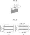
- Fig. 3 is a schematic diagram illustrating a two-fluid nozzle used as the mist-spray nozzle 2 in the present embodiment.
- the mist-spray nozzle is not limited to such an example as long as mist is sprayed at a flow rate in a preferable range.
- mist-spray nozzles 2 In the case where the two-fluid nozzles are used as the mist-spray nozzles 2, as illustrated in Fig. 2 , compressed air which is pressurized and fed by a compressor 52 is supplied to the mist-spray nozzles 2 through a compressed-air pipework 5.
- water which is pressurized and fed by a pump 63 is supplied from a water tank 62 to the mist-spray nozzles 2 through a water pipework 6.
- the opening degrees of a supply valve 51 installed in the compressed-air pipework 5 and a supply valve 61 installed in the water pipework 6 and the operation of the pump 63 are controlled by a flow rate-controlling device 7.
- a filter may be installed in the water pipework 6 in such a manner that the filter is placed between the supply valve 61 and the mist-spray nozzles 2.
- the air-to-water volume ratio of the mist sprayed through the mist-spray nozzles 2 is less than 50, since there is a marked increase in the amount of water adhering to and remaining on the metal sheet 1 in the form of residues, cooling non-uniformity tends to occur.
- the air-to-water volume ratio of the mist sprayed through the mist-spray nozzles 2 be 50 to 1000.
- the mist-spray nozzles 2 are arranged in 80 rows at intervals of 200 mm in the transportation direction of the steel sheet (longitudinal direction of the steel sheet).
- the arrangement of the mist-spray nozzles 2 is not limited to the example described above as long as the nozzles are arranged so that cooling non-uniformity does not occur in the width direction of the metal sheet 1.
- the slit nozzles 2A having a width larger than that of the metal sheet 1 are used as the mist-spray nozzles 2, it is preferable that the slit nozzles be arranged in such a manner that the nozzle interval I in the transportation direction of the steel sheet is 100 mm to 600 mm.
- nozzles 2B having a spray pattern of a spot shape or a cone shape are used as the mist-spray nozzles 2, it is preferable that plural nozzles 2B be arranged in the width direction of the metal sheet 1 in accordance with the specifications of the nozzles. At this time, it is preferable that the nozzles 2B be arranged in such a manner that the mist-spray regions of the nozzles are arranged with no separation or with sufficient overlap so that a uniform cooling rate distribution in the width direction of the metal sheet 1 is achieved. In addition, as illustrated in Fig. 4(b) , it is preferable that the plural nozzles 2B to be arranged in the width direction of the metal sheet 1 be attached to a header 21 when being used.
- mist-spray nozzles 2 may be arranged in a zigzag manner, and the inclination angle of the mist-spray direction from the mist-spray nozzle 2 with respect to the metal sheet 1 or the spread angle of a cone-shaped spray may be adjusted in accordance with the width of the metal sheet 1, which is the object to be cooled, or the like.
- nozzle sets be arranged in such a manner that the interval I between the nozzle sets in the transportation direction of the steel sheet is 100 mm to 600 mm.
- the cooling ability of the cooling fluid-spray device (mist-spray nozzles 2) and the position of the restraining rolls 3 be controlled so that the metal sheet 1 is restrained by using the restraining rolls 3 in a temperature range in which the shape of the metal sheet 1 is most susceptible to being deteriorated. Therefore, in the quenching apparatus and the quenching method for a metal sheet according to the present embodiment, it is preferable that the amount of the mist and the water temperature of the mist, which are adjusted to control the cooling ability, be set as described below.
- the water flow density of the mist 2a be 100 L/m 2 ⁇ min or more and 800 L/m 2 ⁇ min or less. This is because, in the case where the water flow density of the mist 2a is less than 100 L/m 2 ⁇ min, it is not possible to achieve satisfactory mechanical properties of the steel sheet, and, since there is an increase in the distance from the cooling start position to the position of the restraining roll, there is an increase in the size of the equipment.
- the shape of the steel sheet may be deteriorated to such an extent that it is not possible to correct the shape by using the restraining rolls.
- the water flow density of the mist 2a be 200 L/m 2 ⁇ min or more and 500 L/m 2 ⁇ min or less.
- the temperature of the cooling water constituting the droplets of the mist 2a be higher than 0°C and 60°C or lower or particularly preferably 10°C or higher and 50°C or lower from the viewpoint of facility maintenance and achieving a sufficient cooling rate. This is because, in the case where the temperature is 0°C or lower, facility damage may occur due to freezing, and, in the case where the temperature is higher than 60°C, since there is a decrease in cooling rate and there is an increase in the distance from the cooling start position to the position of the restraining roll, there is an increase in the size of the equipment.
- the cooling rate of the metal sheet 1 be 50°C/sec or higher and 500°C/sec or lower. In the case where the cooling rate is lower than 50°C/sec, since there is an increase in the distance from the cooling start position to the position of the restraining roll, there is an increase in the size of the equipment.
- the shape of the steel sheet may be deteriorated to such an extent that it is not possible to correct the shape by using the restraining rolls.
- the restraining rolls 3, which restrain the metal sheet 1 are arranged in a region in which the temperature of the metal sheet 1 is equal to or higher than the Ms temperature and equal to or lower than the Mf temperature.
- Ms temperature denotes the temperature at which martensite transformation of the metal sheet 1 starts
- Mf temperature denotes the temperature at which martensite transformation of the metal sheet 1 finishes.
- the restraining rolls 3 are pressed against the front and back surfaces of the metal sheet 1 to prevent deformation from occurring in the metal sheet 1 when quenching is performed. It is preferable that two rolls constituting one pair of the restraining rolls 3 be arranged with a distance between the central axes thereof in the transporting direction of the metal sheet 1. By arranging the restraining rolls 3 with a distance between the central axes thereof, since it is possible to increase the restraining force applied to the metal sheet 1, it is possible to increase the shape-correcting ability. For example, it is preferable that the restraining rolls 3 be arranged in the transporting direction with a distance of 40 mm or more and 150 mm or less or more preferably 80 mm or more and 100 mm or less between the central axes thereof.
- the metal sheet 1 be pushed by the restraining rolls 3 so that the metal sheet 1 winds around the restraining rolls 3 when the metal sheet passes through the rolls.
- the push-in amount applied by one restraining roll 3 be 0 mm or more and 2.5 mm or less or more preferably 0.5 mm or more and 1.0 mm or less, where a case where the metal sheet 1 passes through in a straight line as illustrated in Fig. 1 is defined as a case of a reference position (0 mm).
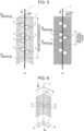
- Fig. 5(a) and Fig. 5(b) are diagrams illustrating mist cooling according to the quenching apparatus and the quenching method for a metal sheet according to the present embodiment and conventional water quenching, respectively, in contradistinction to each other.
- the distance L from the position of the Ms temperature to the position of the Mf temperature is longer than that in the case of a conventional water quenching method illustrated in Fig. 5(b) .
- the distance L from the position of the Ms temperature to the position of the Mf temperature is 100 mm.
- the cooling rate is about 300°C/(sec ⁇ mm)
- the distance L from the position of the Ms temperature to the position of the Mf temperature is more than 1000 mm, since martensite transformation does not sufficiently occur, there may be a case where it is not possible to achieve desired material properties. Therefore, to effectively realize the effect of shape correction due to the restraining rolls 3 in a region from the Ms temperature to the Mf temperature, it is preferable that the distance L from the position of the Ms temperature to the position of the Mf temperature be about 200 mm to 1000 mm.
- the mist 2a may be used across the whole length of the region in which it is necessary to cool the metal sheet 1 including a region in which the temperature of the metal sheet 1 is higher than the Ms temperature and a region in which the temperature of the metal sheet 1 is lower than the Mf temperature.
- the restraining rolls 3 be rotated in the circumferential direction by electric power. Moreover, to adjust the ability for correcting the shape of the metal sheet 1, it is preferable that the restraining rolls 3 be openable and closable, that is, that the push-in amount of the metal sheet 1 be controllable, as needed.
- the restraining rolls 3 be made of a material which is excellent in terms of thermal conductivity and which has sufficient strength to resist a load placed on the rolls when the rolls are pressed onto the metal sheet 1.
- Examples of the material of the restraining rolls 3 include SUS304 or SUS310 prescribed in Japanese Industrial Standards JIS G 4304 "Hot-rolled stainless steel plate, sheet and strip", ceramic, or the like.
- the front and back surfaces of the metal sheet 1 are restrained by four (two pairs of) restraining rolls 3.
- the metal sheet 1 be pushed by the restraining rolls.
- the push-in amount by each of the restraining rolls be 0 mm or more and 2.5 mm or less or particularly preferably 0.5 mm or more and 1.0 mm or less. It is not necessary that the number of the restraining rolls 3 on the front surface of the metal sheet 1 be the same as the number of the restraining rolls 3 on the back surface.
- the same number of the restraining rolls 3 be arranged on both surfaces of the metal sheet 1 so as to form pairs or that the difference in the number of restraining rolls 3 between the front and back surfaces of the metal sheet 1 be 1.
- a dewatering mechanism (not illustrated), with which droplets adhering to and remaining on the restraining rolls 3 in the form of residues are removed, may be placed in the vicinity of the restraining rolls 3.
- a blade-like obstruction, a wiper, an air nozzle, or the like may be used as the examples of such a dewatering mechanism.
- the present invention is intended to reduce a complex, non-uniform recessed and projected shape caused by volume swelling occurring in a microstructure due to martensite transformation occurring when the steel sheet is rapidly cooled, it is preferable that the present invention be used in a method for manufacturing a high strength steel sheet (high tension steel sheet).
- the present invention be used to manufacture a steel sheet having a tensile strength of 580 MPa or higher.
- the tensile strength it is sufficient that the tensile strength be, for example, 1600 MPa or less.
- high strength steel sheet high tension steel sheet
- steel sheets which are manufactured by performing surface treatment on such a high strength cold rolled steel sheet, that is, a galvanized steel sheet, an electrogalvanized steel sheet, a galvannealed steel sheet, and the like.
- the specific examples of the chemical composition of the high strength steel sheet include a chemical composition containing, by mass%, C: 0.04% or more and 0.25% or less, Si: 0.01% or more and 2.50% or less, Mn: 0.80% or more and 3.70% or less, P: 0.001% or more and 0.090% or less, S: 0.0001% or more and 0.0050% or less, sol.Al: 0.005% or more and 0.065% or less, at least one of Cr, Mo, Nb, V, Ni, Cu, and Ti: 0.50 or less each as needed, B and Sb: 0.01% or less each as needed, and the balance being Fe and incidental impurities.
- the embodiments of the present invention are not limited to the examples in which a steel sheet is rapidly cooled, and the embodiments may be used for the quenching of metal sheets in general other than steel sheets.
- a manufacturing test of a steel sheet was performed by using the quenching apparatus and the quenching method for a metal sheet and the method for manufacturing a steel sheet according to the present invention, and the effects were verified. Therefore, the results will be described.
- a high tension cold rolled steel sheet having a thickness of 1.0 mm, a width of 1000 mm, and a tensile strength of a 1470 MPa class was manufactured under the conditions of a threading speed of 1.0 m/s, a quenching start temperature of 800°C, a water flow density of mist of 400 L/m 2 ⁇ min, and a temperature at the time of passing the restraining rolls of 350°C.
- the chemical composition of the high tension cold rolled steel sheet having a tensile strength of a 1470 MPa class contained, by mass%, C: 0.20%, Si: 1.0%, Mn: 2.3%, P: 0.005%, and S: 0.002%.
- the Ms temperature of such a high tension cold rolled steel sheet is 400°C
- the Mf temperature of such a steel sheet is 300°C. Therefore, as described above, since the temperature at the time of passing the restraining rolls may be set to be within a range from 400°C to 300°C, the temperature at the time of passing the restraining rolls was set to be 350°C as described above.
- the restraining rolls were arranged in the threading direction with a distance of 80 mm between the central axes thereof, and the push-in amount of the metal sheet 1 by each of the all the restraining rolls 3 was 0.5 mm.
- each pair of opposing restraining rolls was arranged in the threading direction with a distance of 80 mm between the central axes thereof, and the push-in amount of the metal sheet 1 by each of the all the restraining rolls 3 was 0.5 mm.
- Fig. 8 is a diagram illustrating the definition of the warpage quantity. Specifically, when the steel sheet was placed on a horizontal plane, the height of the highest position thereon was defined as the warpage quantity.
- the warpage quantities of the steel sheets were decreased to a range from 2.0 mm to 8.0 mm, that is, the warpage quantity was decreased to 10 mm or less across the whole length of each of the steel sheets.
- the warpage quantities of the steel sheets were distributed in a range of 10.0 mm to 14.0 mm, that is, the effect of inhibiting deformation was insufficient across the whole length of each of the steel sheets.
- the warpage quantity of the steel sheet was distributed in a range of 4.0 mm to 14.0 mm, that is, the warpage quantity was not decreased to 10 mm or less across the whole length of the steel sheet.
Landscapes
- Chemical & Material Sciences (AREA)
- Engineering & Computer Science (AREA)
- Mechanical Engineering (AREA)
- Materials Engineering (AREA)
- Metallurgy (AREA)
- Organic Chemistry (AREA)
- Physics & Mathematics (AREA)
- Thermal Sciences (AREA)
- Crystallography & Structural Chemistry (AREA)
- Heat Treatment Of Strip Materials And Filament Materials (AREA)
- Heat Treatments In General, Especially Conveying And Cooling (AREA)
Abstract
Description
- The present invention relates to a quenching apparatus and a quenching method for a metal sheet with which it is possible to inhibit shape defects from occurring in the metal sheet when quenching is performed in a continuous annealing system, in which annealing is performed while the metal sheet is continuously threaded, and to a method for manufacturing a steel sheet.
- When a metal sheet such as a steel sheet is manufactured, material properties are imparted by, for example, allowing phase transformation to occur by cooling the metal sheet after having heated the metal sheet in a continuous annealing system. Nowadays, there is a growing demand in the automobile industry for a high strength steel sheet (high tension steel sheet) having reduced thickness to simultaneously achieve weight reduction and satisfactory crash safety in automobile bodies. When such a high tension steel sheet is manufactured, a technique for rapidly cooling the steel sheet is important. In such a cooling process, mist, which is a mixture of a gas and water, a gas such as hydrogen, or the like is generally used as a coolant for the steel sheet. At this time, there is a problem of shape defects such as warpage, wavelike deformation, and the like occurring in the steel sheet due to out-of-plane deformation. To date, various methods have been proposed to prevent such shape defects from occurring when quenching is performed on a steel sheet.
- For example,
Patent Literature 1 discloses a method in which, by appropriately controlling the water flow density in mist sprayed onto a strip, the metal strip is subjected to mist cooling in a film boiling state without transition boiling being induced. - In addition,
Patent Literature 2 discloses a method in which, in a cooling zone in a vertical continuous annealing furnace, in which a strip is continuously annealed while being vertically transported, a temperature variation in the width direction of the strip is inhibited from occurring due to, for example, water contained in mist, which is sprayed onto the strip, dripping down along the surface of the strip. - Moreover,
Patent Literature 3 discloses a method in which a metal sheet being subjected to rapid-cooling quenching is restrained by using a pair of restraining rolls placed in a coolant in a region where the temperature of the metal sheet is in a range from (TMS + 150) (°C) to (TMf -150) (°C), where the Ms temperature, at which martensite transformation starts, is defined as TMs (°C) and the Mf temperature, at which martensite transformation finishes, is defined as TMf (°C). -
- PTL 1:
Japanese Unexamined Patent Application Publication No. 2000-178658 - PTL 2:
Japanese Unexamined Patent Application Publication No. 2009-127060 - PTL 3:
Japanese Patent No. 6094722 - However, from the results obtained by testing the methods according to
Patent Literature 1 andPatent Literature 2, it has been clarified that there is only a small effect of inhibiting shape defects in the case where only the water flow density is controlled or only the temperature variation in the width direction is inhibited. - In addition, from the results obtained by testing the method according to
Patent Literature 3, it has been clarified that there is room for improvement, because, in the case of a method for cooling a steel sheet by dipping the steel sheet in a liquid, since a cooling rate is likely to vary due to the degree of rapid cooling being excessively high, the temperature of the steel sheet tends to vary when the steel sheet passes through the restraining rolls, which may result in a large variation in warpage quantity in the longitudinal direction. - The present invention has been made to solve the problems described above, and an object of the present invention is to provide a quenching apparatus and a quenching method for a metal sheet with which it is possible to inhibit shape defects from occurring in the metal sheet when quenching is performed and to provide a method for manufacturing a steel sheet.
- The present inventors diligently conducted investigations to solve the problems described above and, as a result, obtained the following knowledge. In a method for manufacturing a metal sheet, there is a case where microstructure control is performed by allowing martensite transformation to occur in the metal sheet when quenching is performed, and, in such a case, since volume swelling occurs in the microstructure due to the occurrence of martensite transformation, there may be a case where the metal sheet has a complex, non-uniform recessed and projected shape. When a high tension steel sheet having a martensite microstructure is subjected to quenching, since the largest stress is applied to the steel sheet at a temperature almost within a temperature range from the Ms temperature to the Mf temperature, in which transformation swelling occurs along with thermal shrinkage, there is a deterioration in the shape of the steel sheet. In addition, in this case, the higher the degree of rapid cooling, the more likely the cooling rate is to vary. Therefore, by using mist for cooling so that the degree of rapid cooling is not excessively high, and by arranging restraining rolls, with which a metal sheet is restrained, in a region in which the temperature of the metal sheet is from the Ms temperature to the Mf temperature, it is possible to sufficiently decrease the warpage quantity. Here, the term "Ms temperature" denotes the temperature at which martensite transformation starts, and the term "Mf temperature" denotes the temperature at which martensite transformation finishes.
- The present invention has been made on the basis of the knowledge and the idea described above and has the following features.
- [1] A quenching apparatus for a metal sheet, the apparatus being placed on an exit side of a soaking zone in a continuous annealing furnace, and the apparatus comprising: a cooling fluid-spray device having plural spray nozzles for spraying mist onto both surfaces of a continuously transported metal sheet; and at least one pair of restraining rolls for restraining the metal sheet on both surfaces thereof in a region from a cooling start point to a cooling finish point of the cooling fluid-spray device.
- [2] The quenching apparatus for a metal sheet according to item [1], in which the plural spray nozzles are arranged so that the mist is sprayed onto the metal sheet across a whole temperature range from a martensite start temperature to a martensite finish temperature of the metal sheet.
- [3] The quenching apparatus for a metal sheet according to item [1] or [2], further including a dewatering spray nozzle arranged on a downstream side of an exit of the cooling fluid-spray device.
- [4] A quenching method for a metal sheet, the method comprising spraying mist onto both surfaces of a continuously transported metal sheet to cool the metal sheet while restraining the metal sheet on both surfaces thereof at least in a region in which a temperature of the metal sheet being cooled is from a martensite start temperature to a martensite finish temperature.
- [5] The quenching method for a metal sheet according to item [4], in which a water flow density of the mist is 100 L/m2·min or more and 800 L/m2·min or less.
- [6] A method for manufacturing a steel sheet, the method including continuously annealing a steel sheet and quenching the annealed steel sheet by using the quenching method for a metal sheet according to item [4] or [5] to manufacture one of a high strength cold rolled steel sheet, a galvanized steel sheet, an electrogalvanized steel sheet, and a galvannealed steel sheet.
- According to the quenching apparatus and the quenching method for a metal sheet and the method for manufacturing a steel sheet according to the present invention, it is possible to effectively inhibit shape defects from occurring in the metal sheet when quenching is performed.
-
- [
Fig. 1] Fig. 1 is a diagram illustrating an example of the quenching apparatus and the quenching method for a metal sheet according to the present invention. - [
Fig. 2] Fig. 2 is a diagram illustrating an example of a supply system for supplying air and water to mist-spray nozzles in the quenching apparatus for a metal sheet according to the present invention. - [
Fig. 3] Fig. 3 is a diagram illustrating an example of a two-fluid nozzle. - [
Fig. 4] Fig. 4(a) and Fig. 4(b) are diagrams illustrating examples of a mist-spray nozzle. - [
Fig. 5] Fig. 5(a) and Fig. 5(b) are diagrams illustrating mist cooling according to the quenching apparatus and the quenching method for a metal sheet according to the present invention and conventional water quenching, respectively. - [
Fig. 6] Fig. 6 is a diagram illustrating another example of the quenching apparatus and the quenching method for a metal sheet according to the present invention. - [
Fig. 7] Fig. 7 is a graph illustrating the effect of the quenching apparatus and the quenching method for a metal sheet according to the present invention in contradistinction to the comparative examples. - [
Fig. 8] Fig. 8 is a diagram illustrating the definition of the warpage quantity of a metal sheet inFig. 7 . - Hereafter, embodiments of the quenching apparatus and the quenching method for a metal sheet and the method for manufacturing a steel sheet according to the present invention will be specifically described with reference to the figures.
-
Fig. 1 is a diagram illustrating the quenching apparatus for a metal sheet according to an embodiment of the present invention. This quenching apparatus is used for cooling equipment placed on the exit side of the soaking zone of a continuous annealing furnace. This cooling equipment is placed in order to allow, in the case where the metal sheet which is the object to be cooled is a steel sheet, an austenite phase to transform into a martensite phase during cooling of the steel sheet, thereby achieving the mechanical properties of a final product. Therefore, this cooling equipment has an ability of performing cooling in a temperature range including a temperature range from the martensite start temperature to the martensite finish temperature. - As illustrated in
Fig. 1 , the quenching apparatus for a metal sheet according to the present embodiment includes a cooling fluid-spray device composed of plural mist-spray nozzles (spray nozzles) 2, at least one pair ofrestraining rolls 3, which restrain ametal sheet 1 in a cooling region in the cooling fluid-spray device, and dewateringspray nozzles 4. The mist-spray nozzles 2spray mist 2a, which is a coolant (cooling fluid), onto the continuously threaded metal sheet 1 (for example, a steel sheet) on both surface sides of themetal sheet 1 to perform rapid cooling. Therestraining rolls 3 restrain themetal sheet 1 in a region from a cooling start point, which is the entrance of the cooling fluid-spray device, to a cooling finish point, which is the exit of the cooling fluid-spray device, to prevent deformation. The dewateringspray nozzles 4 are placed on the downstream side of the exit of the cooling fluid-spray device and spray agas 4a such as air, nitrogen, or the like onto themetal sheet 1 from the exit side of themetal sheet 1 to remove dripping water from themetal sheet 1. - Here, the term "mist" denotes atomized water or liquid and an aggregation of minute droplets having a droplet diameter of about 0.01 µm to several hundred µm suspended in a gas. In the present embodiment, by spraying a mixture of water and air, the mist described above is formed. As a result of air being sprayed onto the metal sheet, which is an object to be cooled, at the same time as the minute droplets of water adhere to the metal sheet, it is possible to achieve a sufficient cooling rate. In addition, since water and air reach the metal sheet in a mixture state, it is possible to moderate and stabilize a cooling rate compared with a case where only water is sprayed.
- Here, in the case where the droplet diameter of the mist is less than 10 µm, since the droplets tends to be vaporized, there may be a case where it is not possible to achieve a sufficient cooling rate. In addition, in the case where the droplet diameter of the mist is more than 100 µm, since there is a case where water in a droplet state adheres to and remains on the metal sheet, cooling non-uniformity tends to occur. Therefore, it is preferable that the droplet diameter of the mist be 10 µm or more and 100 µm or less.
- As the mist-
spray nozzle 2, for example, a commercially available product such as a PSN slit nozzle produced by H. IKEUCHI Co.,Ltd., Knife Jet KJIS (internal mixing-type) produced by KYORITSU GOKIN CO., LTD., or the like may be used. -
Fig. 2 is a schematic diagram illustrating a supply system for supplying air and water to the mist-spray nozzles 2 in the quenching apparatus for a metal sheet according to the present embodiment. In addition,Fig. 3 is a schematic diagram illustrating a two-fluid nozzle used as the mist-spray nozzle 2 in the present embodiment. In the present embodiment, although a case where the mist is generated by using the two-fluid nozzles illustrated inFig. 3 as the mist-spray nozzle 2 is used as an example in the description, the mist-spray nozzle is not limited to such an example as long as mist is sprayed at a flow rate in a preferable range. - In the case where the two-fluid nozzles are used as the mist-
spray nozzles 2, as illustrated inFig. 2 , compressed air which is pressurized and fed by acompressor 52 is supplied to the mist-spray nozzles 2 through a compressed-air pipework 5. In addition, water which is pressurized and fed by apump 63 is supplied from awater tank 62 to the mist-spray nozzles 2 through awater pipework 6. Here, the opening degrees of asupply valve 51 installed in the compressed-air pipework 5 and asupply valve 61 installed in thewater pipework 6 and the operation of thepump 63 are controlled by a flow rate-controllingdevice 7. As described above, it is sufficient that the compressed air and the water be supplied to the mist-spray nozzles 2 in such a manner that the pressures and amounts of the compressed air and the water are within the allowable ranges in accordance with the specifications of the mist-spray nozzles 2. In addition, to prevent the mist-spray nozzles 2 from clogging, a filter may be installed in thewater pipework 6 in such a manner that the filter is placed between thesupply valve 61 and the mist-spray nozzles 2. - Here, in the case where the air-to-water volume ratio of the mist sprayed through the mist-
spray nozzles 2 is less than 50, since there is a marked increase in the amount of water adhering to and remaining on themetal sheet 1 in the form of residues, cooling non-uniformity tends to occur. In addition, in the case where such an air-to-water volume ratio is more than 1000, since there is an excessive decrease in the droplet diameter of the mist, there may be a case where it is not possible to achieve a cooling rate necessary for achieving the properties which themetal sheet 1 is required to have. Therefore, it is preferable that the air-to-water volume ratio of the mist sprayed through the mist-spray nozzles 2 be 50 to 1000. - In the case of the quenching apparatus for a metal sheet according to the present embodiment, the mist-
spray nozzles 2 are arranged in 80 rows at intervals of 200 mm in the transportation direction of the steel sheet (longitudinal direction of the steel sheet). - However, the arrangement of the mist-
spray nozzles 2 is not limited to the example described above as long as the nozzles are arranged so that cooling non-uniformity does not occur in the width direction of themetal sheet 1. For example, as illustrated inFig. 4(a) , in the case whereslit nozzles 2A having a width larger than that of themetal sheet 1 are used as the mist-spray nozzles 2, it is preferable that the slit nozzles be arranged in such a manner that the nozzle interval I in the transportation direction of the steel sheet is 100 mm to 600 mm. This is because, in the case where the nozzle interval I in the transportation direction of the steel sheet is less than 100 mm, since the mist-spray regions of the nozzles interfere with each other, there may be a case where it is difficult to predict a cooling rate, and, in the case where the nozzle interval I in the transportation direction of the steel sheet is more than 600 mm, there may be a case where it is not possible to achieve a sufficient cooling rate. - In addition, as illustrated in
Fig. 4(b) , in the case wherenozzles 2B having a spray pattern of a spot shape or a cone shape are used as the mist-spray nozzles 2, it is preferable thatplural nozzles 2B be arranged in the width direction of themetal sheet 1 in accordance with the specifications of the nozzles. At this time, it is preferable that thenozzles 2B be arranged in such a manner that the mist-spray regions of the nozzles are arranged with no separation or with sufficient overlap so that a uniform cooling rate distribution in the width direction of themetal sheet 1 is achieved. In addition, as illustrated inFig. 4(b) , it is preferable that theplural nozzles 2B to be arranged in the width direction of themetal sheet 1 be attached to aheader 21 when being used. - In addition, the mist-
spray nozzles 2 may be arranged in a zigzag manner, and the inclination angle of the mist-spray direction from the mist-spray nozzle 2 with respect to themetal sheet 1 or the spread angle of a cone-shaped spray may be adjusted in accordance with the width of themetal sheet 1, which is the object to be cooled, or the like. - Also in the case where plural nozzles are used in one set in which the nozzles are arranged in the width direction of the
metal sheet 1 to achieve uniform cooling ability in the width direction of themetal sheet 1 as described above, it is preferable that such nozzle sets be arranged in such a manner that the interval I between the nozzle sets in the transportation direction of the steel sheet is 100 mm to 600 mm. This is because, in the case where the interval I between the nozzle sets in the transportation direction of the steel sheet is less than 100 mm, since the mist-spray regions of the nozzles interfere with each other, there may be a case where it is difficult to predict a cooling rate, and, in the case where the interval I between the nozzle sets in the transportation direction of the steel sheet is more than 600 mm, there may be a case where it is not possible to achieve a sufficient cooling rate. - Here, in the present invention, it is important that the relation between the cooling ability of the cooling fluid-spray device (mist-spray nozzles 2) and the position of the restraining rolls 3 be controlled so that the
metal sheet 1 is restrained by using the restraining rolls 3 in a temperature range in which the shape of themetal sheet 1 is most susceptible to being deteriorated. Therefore, in the quenching apparatus and the quenching method for a metal sheet according to the present embodiment, it is preferable that the amount of the mist and the water temperature of the mist, which are adjusted to control the cooling ability, be set as described below. - First, in the case where quenching is performed by using a method in which
mist 2a is sprayed from the plural mist-spray nozzles 2 onto the surface of themetal sheet 1, it is preferable that the water flow density of themist 2a be 100 L/m2·min or more and 800 L/m2·min or less. This is because, in the case where the water flow density of themist 2a is less than 100 L/m2·min, it is not possible to achieve satisfactory mechanical properties of the steel sheet, and, since there is an increase in the distance from the cooling start position to the position of the restraining roll, there is an increase in the size of the equipment. In addition, in the case where the water flow density of themist 2a is more than 800 L/m2·min, since unstable cooling occurs due to a decrease in cooling time from the start of cooling to the arrival at the restraining roll, the shape of the steel sheet may be deteriorated to such an extent that it is not possible to correct the shape by using the restraining rolls. - In addition, it is more preferable that the water flow density of the
mist 2a be 200 L/m2·min or more and 500 L/m2·min or less. - In addition, it is preferable that the temperature of the cooling water constituting the droplets of the
mist 2a be higher than 0°C and 60°C or lower or particularly preferably 10°C or higher and 50°C or lower from the viewpoint of facility maintenance and achieving a sufficient cooling rate. This is because, in the case where the temperature is 0°C or lower, facility damage may occur due to freezing, and, in the case where the temperature is higher than 60°C, since there is a decrease in cooling rate and there is an increase in the distance from the cooling start position to the position of the restraining roll, there is an increase in the size of the equipment. - In the case of a vertical mist cooling device, since water contained in the
mist 2a flows down along themetal sheet 1 to cause a negative effect on the cooling of a lower part, it is preferable that measures be taken to prevent water from dripping, and, for example, it is possible to control such a situation by spraying themist 2a and thegas 4a at an upward angle of about 30 degrees. - At this time, for the reasons described above, to arrange the restraining rolls practically and effectively in accordance with the cooling ability, it is preferable that the cooling rate of the
metal sheet 1 be 50°C/sec or higher and 500°C/sec or lower. In the case where the cooling rate is lower than 50°C/sec, since there is an increase in the distance from the cooling start position to the position of the restraining roll, there is an increase in the size of the equipment. On the other hand, in the case where the cooling rate is higher than 500°C/sec, since unstable cooling occurs due to a decrease in cooling time from the start of cooling to the arrival at the restraining roll, the shape of the steel sheet may be deteriorated to such an extent that it is not possible to correct the shape by using the restraining rolls. - As described above, by using the
mist 2a and by controlling the cooling rate to be within the preferable range, it is possible to improve the effect of shape correction due to the restraining rolls 3. - In the present embodiment, when quenching is performed by using a method in which the
mist 2a is sprayed onto the surface of themetal sheet 1 through the plural mist-spray nozzles 2 to cool the metal sheet, the restraining rolls 3, which restrain themetal sheet 1, are arranged in a region in which the temperature of themetal sheet 1 is equal to or higher than the Ms temperature and equal to or lower than the Mf temperature. Here, the term "Ms temperature" denotes the temperature at which martensite transformation of themetal sheet 1 starts, and the term "Mf temperature" denotes the temperature at which martensite transformation of themetal sheet 1 finishes. Incidentally, it is possible to calculate the Ms temperature and the Mf temperature from the chemical composition of themetal sheet 1. - The restraining rolls 3 are pressed against the front and back surfaces of the
metal sheet 1 to prevent deformation from occurring in themetal sheet 1 when quenching is performed. It is preferable that two rolls constituting one pair of the restraining rolls 3 be arranged with a distance between the central axes thereof in the transporting direction of themetal sheet 1. By arranging the restraining rolls 3 with a distance between the central axes thereof, since it is possible to increase the restraining force applied to themetal sheet 1, it is possible to increase the shape-correcting ability. For example, it is preferable that the restraining rolls 3 be arranged in the transporting direction with a distance of 40 mm or more and 150 mm or less or more preferably 80 mm or more and 100 mm or less between the central axes thereof. - In addition, it is preferable that the
metal sheet 1 be pushed by the restraining rolls 3 so that themetal sheet 1 winds around the restraining rolls 3 when the metal sheet passes through the rolls. As a result of themetal sheet 1 being pushed by the restraining rolls 3, it is possible to increase the ability for correcting the shape of a steel sheet, and it is possible to prevent the restraining rolls 3 from rotating idly. It is preferable that the push-in amount applied by one restrainingroll 3 be 0 mm or more and 2.5 mm or less or more preferably 0.5 mm or more and 1.0 mm or less, where a case where themetal sheet 1 passes through in a straight line as illustrated inFig. 1 is defined as a case of a reference position (0 mm). -
Fig. 5(a) and Fig. 5(b) are diagrams illustrating mist cooling according to the quenching apparatus and the quenching method for a metal sheet according to the present embodiment and conventional water quenching, respectively, in contradistinction to each other. In the case where cooling is performed moderately by using a mist cooling method from the Ms temperature to the Mf temperature as illustrated inFig. 5(a) , the distance L from the position of the Ms temperature to the position of the Mf temperature is longer than that in the case of a conventional water quenching method illustrated inFig. 5(b) . Therefore, it is possible to flexibly respond to a change in the threading speed or thickness of themetal sheet 1 in such a manner that the restraining rolls 3 are used in an appropriate temperature range or that the number of the restraining rolls 3 to be used for restraining is increased or decreased more easily than in the case of a conventional water quenching method. - For example, when the thickness multiplied by the threading speed is 1.5 (m/sec)·mm and the difference between the Ms temperature and the Mf temperature is 100°C, in the case where water quenching illustrated in
Fig. 5(b) is performed at a cooling rate of 1500°C/(sec·mm), the distance L from the position of the Ms temperature to the position of the Mf temperature is 100 mm. On the other hand, in the case of the mist cooling illustrated inFig. 5(a) , since the cooling rate is about 300°C/(sec·mm), it is possible to increase the distance L from the position of the Ms temperature to the position of the Mf temperature to 500 mm. Therefore, by arranging plural restraining rolls 3 in the distance L (500 mm) from the position of the Ms temperature to the position of the Mf temperature, it is possible to restrain themetal sheet 1 in a temperature range from the Ms temperature to the Mf temperature with certainty, thereby performing shape correction with certainty. In addition, it is also easy to flexibly respond to a temporary change in restraining position due to a change in threading speed, thickness, or the like. - Here, in the case of the quenching apparatus and quenching method for a metal sheet according to the present embodiment illustrated in
Fig. 5(a) , when the distance L from the position of the Ms temperature to the position of the Mf temperature is less than 200 mm, as in the case of water quenching illustrated inFig. 5(b) , it is difficult to flexibly respond to a change in the threading speed or thickness of themetal sheet 1. Therefore, there may be a case where it is not possible to sufficiently realize the effect of shape correction due to the restraining rolls 3. In addition, when the distance L from the position of the Ms temperature to the position of the Mf temperature is more than 1000 mm, since martensite transformation does not sufficiently occur, there may be a case where it is not possible to achieve desired material properties. Therefore, to effectively realize the effect of shape correction due to the restraining rolls 3 in a region from the Ms temperature to the Mf temperature, it is preferable that the distance L from the position of the Ms temperature to the position of the Mf temperature be about 200 mm to 1000 mm. - Moreover, the
mist 2a may be used across the whole length of the region in which it is necessary to cool themetal sheet 1 including a region in which the temperature of themetal sheet 1 is higher than the Ms temperature and a region in which the temperature of themetal sheet 1 is lower than the Mf temperature. - To prevent roll flaws from occurring in the
metal sheet 1, it is preferable that the restraining rolls 3 be rotated in the circumferential direction by electric power. Moreover, to adjust the ability for correcting the shape of themetal sheet 1, it is preferable that the restraining rolls 3 be openable and closable, that is, that the push-in amount of themetal sheet 1 be controllable, as needed. - It is sufficient that the restraining rolls 3 be made of a material which is excellent in terms of thermal conductivity and which has sufficient strength to resist a load placed on the rolls when the rolls are pressed onto the
metal sheet 1. Examples of the material of the restraining rolls 3 include SUS304 or SUS310 prescribed in Japanese Industrial Standards JIS G 4304 "Hot-rolled stainless steel plate, sheet and strip", ceramic, or the like. - Hereafter, with reference to
Fig. 6 , an example in which three or more of the restraining rolls 3 are used will be described. In the description below, description similarly applicable to the case where one pair of the restraining rolls 3 are used may be omitted. - In the example in
Fig. 6 , the front and back surfaces of themetal sheet 1 are restrained by four (two pairs of) restraining rolls 3. In the case where plural pairs of restraining rolls are used, for the same reasons as in the case where only two (one pair of) restraining rolls are used, it is preferable that themetal sheet 1 be pushed by the restraining rolls. It is preferable that the push-in amount by each of the restraining rolls be 0 mm or more and 2.5 mm or less or particularly preferably 0.5 mm or more and 1.0 mm or less. It is not necessary that the number of the restraining rolls 3 on the front surface of themetal sheet 1 be the same as the number of the restraining rolls 3 on the back surface. However, to equally apply restraining force to both surfaces of themetal sheet 1, it is preferable that the same number of the restraining rolls 3 be arranged on both surfaces of themetal sheet 1 so as to form pairs or that the difference in the number of restraining rolls 3 between the front and back surfaces of themetal sheet 1 be 1. - In an example in which three or more of the restraining rolls are used, it is possible to achieve a higher ability for correcting the shape of a steel sheet when cooling is performed compared with the case where only two (one pair of) restraining rolls are used. In particular, even in the case where a high strength steel sheet, in which deformation tends to occur, is cooled, by using three or more of restraining rolls 3, it is possible to inhibit, with a higher degree of certainty, deformation such as warpage occurring in the steel sheet when cooling is performed. On the other hand, in the case where the number of the restraining rolls is excessively large, there is a problem regarding facility conditions or a problem of a decrease in the cooling ability of the spray device. Therefore, it is sufficient that the number of the restraining rolls be appropriately decided in consideration of such problems.
- In addition, as in the case of the present embodiment, when cooling with the
mist 2a and the restraining rolls 3 are simultaneously used, there may be a case where themist 2a adheres to and remains on the restraining rolls 3 in the form of residues and the amount ofsuch mist 2a varies in the width direction of the metal sheet 1 (that is, the axial direction of the restraining rolls 3). As a result, since cooling non-uniformity occurs, there may be a decrease in the effect of shape correction due to the restraining rolls 3. Therefore, to solve such a problem, a dewatering mechanism (not illustrated), with which droplets adhering to and remaining on the restraining rolls 3 in the form of residues are removed, may be placed in the vicinity of the restraining rolls 3. Specifically, as the examples of such a dewatering mechanism, a blade-like obstruction, a wiper, an air nozzle, or the like may be used. - As described above, since the present invention is intended to reduce a complex, non-uniform recessed and projected shape caused by volume swelling occurring in a microstructure due to martensite transformation occurring when the steel sheet is rapidly cooled, it is preferable that the present invention be used in a method for manufacturing a high strength steel sheet (high tension steel sheet).
- More specifically, it is preferable that the present invention be used to manufacture a steel sheet having a tensile strength of 580 MPa or higher. Although there is no particular limitation on the upper limit of the tensile strength, it is sufficient that the tensile strength be, for example, 1600 MPa or less.
- Examples of the high strength steel sheet (high tension steel sheet) described above include a high strength cold rolled steel sheet and steel sheets which are manufactured by performing surface treatment on such a high strength cold rolled steel sheet, that is, a galvanized steel sheet, an electrogalvanized steel sheet, a galvannealed steel sheet, and the like.
- The specific examples of the chemical composition of the high strength steel sheet include a chemical composition containing, by mass%, C: 0.04% or more and 0.25% or less, Si: 0.01% or more and 2.50% or less, Mn: 0.80% or more and 3.70% or less, P: 0.001% or more and 0.090% or less, S: 0.0001% or more and 0.0050% or less, sol.Al: 0.005% or more and 0.065% or less, at least one of Cr, Mo, Nb, V, Ni, Cu, and Ti: 0.50 or less each as needed, B and Sb: 0.01% or less each as needed, and the balance being Fe and incidental impurities.
- Incidentally, the embodiments of the present invention are not limited to the examples in which a steel sheet is rapidly cooled, and the embodiments may be used for the quenching of metal sheets in general other than steel sheets.
- A manufacturing test of a steel sheet was performed by using the quenching apparatus and the quenching method for a metal sheet and the method for manufacturing a steel sheet according to the present invention, and the effects were verified. Therefore, the results will be described.
- By using the quenching apparatus for a metal sheet illustrated in
Fig. 1 , a high tension cold rolled steel sheet having a thickness of 1.0 mm, a width of 1000 mm, and a tensile strength of a 1470 MPa class was manufactured under the conditions of a threading speed of 1.0 m/s, a quenching start temperature of 800°C, a water flow density of mist of 400 L/m2·min, and a temperature at the time of passing the restraining rolls of 350°C. - Here, the chemical composition of the high tension cold rolled steel sheet having a tensile strength of a 1470 MPa class contained, by mass%, C: 0.20%, Si: 1.0%, Mn: 2.3%, P: 0.005%, and S: 0.002%.
- Incidentally, the Ms temperature of such a high tension cold rolled steel sheet is 400°C, and the Mf temperature of such a steel sheet is 300°C. Therefore, as described above, since the temperature at the time of passing the restraining rolls may be set to be within a range from 400°C to 300°C, the temperature at the time of passing the restraining rolls was set to be 350°C as described above.
- Here, the restraining rolls were arranged in the threading direction with a distance of 80 mm between the central axes thereof, and the push-in amount of the
metal sheet 1 by each of the all the restraining rolls 3 was 0.5 mm. - By using the quenching apparatus illustrated in
Fig. 6 , an operation was performed under the same conditions as in the case of Example 1. Here, each pair of opposing restraining rolls was arranged in the threading direction with a distance of 80 mm between the central axes thereof, and the push-in amount of themetal sheet 1 by each of the all the restraining rolls 3 was 0.5 mm. - As a comparative example, with the exception that the cooling apparatus according to
Patent Literature 1 was used, the high tension cold rolled steel sheet described above was manufactured under the same conditions as in the case of the examples. - As a comparative example, with the exception that the cooling apparatus according to
Patent Literature 2 was used, the high tension cold rolled steel sheet described above was manufactured under the same conditions as in the case of the examples. - As a comparative example, with the exception that the cooling apparatus according to
Patent Literature 3 was used, the high tension cold rolled steel sheet described above was manufactured under the same conditions as in the case of the examples. - Then, in each of the cases (Examples 1 to 2, and Comparative examples 1 to 3), 10 samples were taken from the cooled steel sheet at intervals of 100 m in the longitudinal direction, and the warpage quantity of each of the 10 samples was investigated. Here,
Fig. 8 is a diagram illustrating the definition of the warpage quantity. Specifically, when the steel sheet was placed on a horizontal plane, the height of the highest position thereon was defined as the warpage quantity. - The results of Examples 1 to 2 and Comparative examples 1 to 3 are shown in
Fig. 7 . - In the case of Examples 1 to 2, the warpage quantities of the steel sheets were decreased to a range from 2.0 mm to 8.0 mm, that is, the warpage quantity was decreased to 10 mm or less across the whole length of each of the steel sheets. In contrast, in the case of Comparative examples 1 to 2, the warpage quantities of the steel sheets were distributed in a range of 10.0 mm to 14.0 mm, that is, the effect of inhibiting deformation was insufficient across the whole length of each of the steel sheets. In addition, in the case of Comparative example 3, the warpage quantity of the steel sheet was distributed in a range of 4.0 mm to 14.0 mm, that is, the warpage quantity was not decreased to 10 mm or less across the whole length of the steel sheet.
- From the results described above, the effectiveness of the quenching apparatus and the quenching method for a metal sheet and the method for manufacturing a steel sheet according to the present invention was clarified.
-
- 1
- metal sheet
- 2 (2A, 2B)
- mist-spray nozzle (spray nozzle)
- 2a
- mist
- 21
- header
- 3
- restraining roll
- 4
- dewatering spray nozzle
- 4a
- gas
- 5
- compressed-air pipework
- 51
- supply valve
- 52
- compressor
- 6
- water pipework
- 61
- supply valve
- 62
- water tank
- 63
- pump
- 7
- flow rate-controlling device
Claims (6)
- A quenching apparatus for a metal sheet, the apparatus being placed on an exit side of a soaking zone in a continuous annealing furnace, and the apparatus comprising:a cooling fluid-spray device having plural spray nozzles for spraying mist onto both surfaces of a continuously transported metal sheet; andat least one pair of restraining rolls for restraining the metal sheet on both surfaces thereof in a region from a cooling start point to a cooling finish point of the cooling fluid-spray device.
- The quenching apparatus for a metal sheet according to Claim 1, wherein the plural spray nozzles are arranged so that the mist is sprayed onto the metal sheet across a whole temperature range from a martensite start temperature to a martensite finish temperature of the metal sheet.
- The quenching apparatus for a metal sheet according to Claim 1 or 2, further comprising a dewatering spray nozzle arranged on a downstream side of an exit of the cooling fluid-spray device.
- A quenching method for a metal sheet, the method comprising spraying mist onto both surfaces of a continuously transported metal sheet to cool the metal sheet while restraining the metal sheet on both surfaces thereof at least in a region in which a temperature of the metal sheet being cooled is from a martensite start temperature to a martensite finish temperature.
- The quenching method for a metal sheet according to Claim 4, wherein a water flow density of the mist is 100 L/m2·min or more and 800 L/m2·min or less.
- A method for manufacturing a steel sheet, the method comprising continuously annealing a steel sheet and quenching the annealed steel sheet by using the quenching method for a metal sheet according to Claim 4 or 5 to manufacture one of a high strength cold rolled steel sheet, a galvanized steel sheet, an electrogalvanized steel sheet, and a galvannealed steel sheet.
Applications Claiming Priority (2)
| Application Number | Priority Date | Filing Date | Title |
|---|---|---|---|
| JP2021012721 | 2021-01-29 | ||
| PCT/JP2021/039666 WO2022163044A1 (en) | 2021-01-29 | 2021-10-27 | Metal sheet quench-hardening apparatus and quench-hardening method, and steel sheet production method |
Publications (2)
| Publication Number | Publication Date |
|---|---|
| EP4257709A1 true EP4257709A1 (en) | 2023-10-11 |
| EP4257709A4 EP4257709A4 (en) | 2024-04-10 |
Family
ID=82654409
Family Applications (1)
| Application Number | Title | Priority Date | Filing Date |
|---|---|---|---|
| EP21923050.5A Pending EP4257709A4 (en) | 2021-01-29 | 2021-10-27 | DEVICE FOR QUENCHING-HARDENING METAL SHEETS AND METHOD FOR HARDENING METAL SHEETS AND METHOD FOR PRODUCING STEEL SHEETS |
Country Status (7)
| Country | Link |
|---|---|
| US (1) | US20240301524A1 (en) |
| EP (1) | EP4257709A4 (en) |
| JP (1) | JP7338783B2 (en) |
| KR (1) | KR20230122656A (en) |
| CN (1) | CN116745446A (en) |
| MX (1) | MX2023008750A (en) |
| WO (1) | WO2022163044A1 (en) |
Family Cites Families (14)
| Publication number | Priority date | Publication date | Assignee | Title |
|---|---|---|---|---|
| JPS5846116Y2 (en) * | 1979-12-20 | 1983-10-20 | 川崎製鉄株式会社 | Rapid cooling device for continuous annealing equipment |
| FR2571384A1 (en) * | 1984-10-09 | 1986-04-11 | Bertin & Cie | PROCESS OF HARDENING HARDWARE OF METAL SHEETS SUCH AS STEEL AND INSTALLATION FOR IMPLEMENTING SAME |
| JP4109365B2 (en) | 1998-12-08 | 2008-07-02 | 新日本製鐵株式会社 | Metal strip cooling method |
| KR100529055B1 (en) * | 2001-12-07 | 2005-11-15 | 주식회사 포스코 | Device for cooling strip in continuous annealing furnace |
| US7163047B2 (en) * | 2005-03-21 | 2007-01-16 | Nucor Corporation | Pinch roll apparatus and method for operating the same |
| JP5097394B2 (en) * | 2006-12-19 | 2012-12-12 | 住友金属工業株式会社 | Cold rolled steel sheet manufacturing method and manufacturing apparatus |
| JP5100327B2 (en) | 2007-11-20 | 2012-12-19 | 住友金属工業株式会社 | Cold rolled steel sheet manufacturing method |
| JP6252833B2 (en) * | 2013-09-30 | 2017-12-27 | 日立金属株式会社 | Method for producing martensitic stainless steel strip |
| FR3014447B1 (en) * | 2013-12-05 | 2016-02-05 | Fives Stein | METHOD AND INSTALLATION FOR CONTINUOUS THERMAL TREATMENT OF A STEEL BAND |
| EP3225705B1 (en) * | 2014-11-28 | 2020-11-04 | JFE Steel Corporation | Method for manufacturing metal plates and quenching device |
| JP6308287B2 (en) * | 2015-12-28 | 2018-04-11 | Jfeスチール株式会社 | Rapid quenching apparatus and quench quenching method |
| JP6624113B2 (en) * | 2017-02-21 | 2019-12-25 | Jfeスチール株式会社 | Quenching and quenching equipment |
| KR102430332B1 (en) * | 2017-10-31 | 2022-08-05 | 제이에프이 스틸 가부시키가이샤 | Steel plate manufacturing equipment and manufacturing method |
| JP6687084B2 (en) * | 2017-11-15 | 2020-04-22 | Jfeスチール株式会社 | Quenching and quenching apparatus, quenching and quenching method, and method for manufacturing metal plate product |
-
2021
- 2021-10-27 MX MX2023008750A patent/MX2023008750A/en unknown
- 2021-10-27 JP JP2022506877A patent/JP7338783B2/en active Active
- 2021-10-27 CN CN202180091643.XA patent/CN116745446A/en active Pending
- 2021-10-27 KR KR1020237025013A patent/KR20230122656A/en active Pending
- 2021-10-27 WO PCT/JP2021/039666 patent/WO2022163044A1/en not_active Ceased
- 2021-10-27 EP EP21923050.5A patent/EP4257709A4/en active Pending
- 2021-10-27 US US18/273,830 patent/US20240301524A1/en active Pending
Also Published As
| Publication number | Publication date |
|---|---|
| JPWO2022163044A1 (en) | 2022-08-04 |
| EP4257709A4 (en) | 2024-04-10 |
| KR20230122656A (en) | 2023-08-22 |
| JP7338783B2 (en) | 2023-09-05 |
| CN116745446A (en) | 2023-09-12 |
| WO2022163044A1 (en) | 2022-08-04 |
| MX2023008750A (en) | 2023-08-01 |
| US20240301524A1 (en) | 2024-09-12 |
Similar Documents
| Publication | Publication Date | Title |
|---|---|---|
| EP3399056B1 (en) | Rapid cooling quenching device and rapid cooling quenching method | |
| EP3205741B1 (en) | Continuous hot-dip metal plating method and continuous hot-dip metal plating equipment | |
| KR101128316B1 (en) | Continuous annealing equipment | |
| EP2415536A1 (en) | Cooling device for hot rolled steel sheet | |
| EP3705587A1 (en) | Facility and method for producing thick steel sheet | |
| JP6870701B2 (en) | Steel sheet cooling method, steel sheet cooling device and steel sheet manufacturing method | |
| JP6687084B2 (en) | Quenching and quenching apparatus, quenching and quenching method, and method for manufacturing metal plate product | |
| EP2979769B1 (en) | Thick steel plate manufacturing method and manufacturing device | |
| EP4257709A1 (en) | Metal sheet quench-hardening apparatus and quench-hardening method, and steel sheet production method | |
| US12365956B2 (en) | Metal-strip rapid cooling apparatus, metal-strip rapid cooling method, and method of producing metal strip product | |
| CN113165060A (en) | Method for continuously casting steel | |
| WO2020085352A1 (en) | Quenching device, quenching method, and metal plate production method | |
| US20240344158A1 (en) | Quenching apparatus for metal sheet, continuous annealing equipment, method for quenching metal sheet, method for manufacturing cold rolled steel sheet, and method for manufacturing coated steel sheet | |
| JP6687090B2 (en) | Quenching and quenching apparatus, quenching and quenching method, and method for manufacturing metal plate product | |
| JPWO2020085353A1 (en) | Quenching equipment, quenching method, and steel sheet manufacturing method | |
| EP4372106A1 (en) | Quench-hardening apparatus, quench-hardening method, and metal sheet manufacturing method | |
| EP4365321A1 (en) | Quenching apparatus, continuous annealing facility, quenching method, steel sheet production method, and plated steel sheet production method | |
| JP7180636B2 (en) | Apparatus for quenching metal plate, method for quenching metal plate, and method for manufacturing steel plate | |
| EP4365320A1 (en) | Quenching device, continuous annealing equipment, quenching method, method for manufacturing steel sheet, and method for manufacturing plated steel sheet | |
| JP2019081198A (en) | Manufacturing method and manufacturing equipment of steel material | |
| KR101505271B1 (en) | Gas wiping apparatus and method of manufacturing galvannealed steel sheet using the same |
Legal Events
| Date | Code | Title | Description |
|---|---|---|---|
| STAA | Information on the status of an ep patent application or granted ep patent |
Free format text: STATUS: THE INTERNATIONAL PUBLICATION HAS BEEN MADE |
|
| PUAI | Public reference made under article 153(3) epc to a published international application that has entered the european phase |
Free format text: ORIGINAL CODE: 0009012 |
|
| STAA | Information on the status of an ep patent application or granted ep patent |
Free format text: STATUS: REQUEST FOR EXAMINATION WAS MADE |
|
| 17P | Request for examination filed |
Effective date: 20230701 |
|
| AK | Designated contracting states |
Kind code of ref document: A1 Designated state(s): AL AT BE BG CH CY CZ DE DK EE ES FI FR GB GR HR HU IE IS IT LI LT LU LV MC MK MT NL NO PL PT RO RS SE SI SK SM TR |
|
| REG | Reference to a national code |
Ref country code: DE Ref legal event code: R079 Free format text: PREVIOUS MAIN CLASS: C21D0009520000 Ipc: C21D0001667000 |
|
| A4 | Supplementary search report drawn up and despatched |
Effective date: 20240311 |
|
| RIC1 | Information provided on ipc code assigned before grant |
Ipc: C21D 9/00 20060101ALN20240304BHEP Ipc: C21D 8/02 20060101ALN20240304BHEP Ipc: C22C 38/60 20060101ALI20240304BHEP Ipc: C22C 38/06 20060101ALI20240304BHEP Ipc: C22C 38/00 20060101ALI20240304BHEP Ipc: C21D 9/46 20060101ALI20240304BHEP Ipc: C21D 1/60 20060101ALI20240304BHEP Ipc: C21D 1/613 20060101ALI20240304BHEP Ipc: B21B 45/02 20060101ALI20240304BHEP Ipc: C21D 1/26 20060101ALI20240304BHEP Ipc: C21D 9/573 20060101ALI20240304BHEP Ipc: C21D 9/52 20060101ALI20240304BHEP Ipc: C21D 1/18 20060101ALI20240304BHEP Ipc: C21D 1/667 20060101AFI20240304BHEP |
|
| DAV | Request for validation of the european patent (deleted) | ||
| DAX | Request for extension of the european patent (deleted) |