EP4257529A1 - Hose box - Google Patents
Hose box Download PDFInfo
- Publication number
- EP4257529A1 EP4257529A1 EP23159672.7A EP23159672A EP4257529A1 EP 4257529 A1 EP4257529 A1 EP 4257529A1 EP 23159672 A EP23159672 A EP 23159672A EP 4257529 A1 EP4257529 A1 EP 4257529A1
- Authority
- EP
- European Patent Office
- Prior art keywords
- hose
- drum
- cavity
- housing
- box according
- Prior art date
- Legal status (The legal status is an assumption and is not a legal conclusion. Google has not performed a legal analysis and makes no representation as to the accuracy of the status listed.)
- Pending
Links
- 230000008878 coupling Effects 0.000 claims abstract description 22
- 238000010168 coupling process Methods 0.000 claims abstract description 22
- 238000005859 coupling reaction Methods 0.000 claims abstract description 22
- 238000004804 winding Methods 0.000 claims abstract description 5
- 230000001681 protective effect Effects 0.000 description 7
- HBBGRARXTFLTSG-UHFFFAOYSA-N Lithium ion Chemical compound [Li+] HBBGRARXTFLTSG-UHFFFAOYSA-N 0.000 description 2
- 239000000428 dust Substances 0.000 description 2
- 229910001416 lithium ion Inorganic materials 0.000 description 2
- XLYOFNOQVPJJNP-UHFFFAOYSA-N water Substances O XLYOFNOQVPJJNP-UHFFFAOYSA-N 0.000 description 2
- OJIJEKBXJYRIBZ-UHFFFAOYSA-N cadmium nickel Chemical compound [Ni].[Cd] OJIJEKBXJYRIBZ-UHFFFAOYSA-N 0.000 description 1
- 239000004020 conductor Substances 0.000 description 1
- 230000001419 dependent effect Effects 0.000 description 1
- 238000011161 development Methods 0.000 description 1
- 230000018109 developmental process Effects 0.000 description 1
- 230000000694 effects Effects 0.000 description 1
- 238000007373 indentation Methods 0.000 description 1
- 238000012423 maintenance Methods 0.000 description 1
- 229920000642 polymer Polymers 0.000 description 1
- 238000007789 sealing Methods 0.000 description 1
Images


Classifications
-
- B—PERFORMING OPERATIONS; TRANSPORTING
- B65—CONVEYING; PACKING; STORING; HANDLING THIN OR FILAMENTARY MATERIAL
- B65H—HANDLING THIN OR FILAMENTARY MATERIAL, e.g. SHEETS, WEBS, CABLES
- B65H75/00—Storing webs, tapes, or filamentary material, e.g. on reels
- B65H75/02—Cores, formers, supports, or holders for coiled, wound, or folded material, e.g. reels, spindles, bobbins, cop tubes, cans, mandrels or chucks
- B65H75/34—Cores, formers, supports, or holders for coiled, wound, or folded material, e.g. reels, spindles, bobbins, cop tubes, cans, mandrels or chucks specially adapted or mounted for storing and repeatedly paying-out and re-storing lengths of material provided for particular purposes, e.g. anchored hoses, power cables
- B65H75/38—Cores, formers, supports, or holders for coiled, wound, or folded material, e.g. reels, spindles, bobbins, cop tubes, cans, mandrels or chucks specially adapted or mounted for storing and repeatedly paying-out and re-storing lengths of material provided for particular purposes, e.g. anchored hoses, power cables involving the use of a core or former internal to, and supporting, a stored package of material
- B65H75/44—Constructional details
- B65H75/4457—Arrangements of the frame or housing
- B65H75/446—Arrangements of the frame or housing for releasably or permanently attaching the frame to a wall, on a floor or on a post or the like
- B65H75/4463—Swivelling attachment
-
- B—PERFORMING OPERATIONS; TRANSPORTING
- B65—CONVEYING; PACKING; STORING; HANDLING THIN OR FILAMENTARY MATERIAL
- B65H—HANDLING THIN OR FILAMENTARY MATERIAL, e.g. SHEETS, WEBS, CABLES
- B65H75/00—Storing webs, tapes, or filamentary material, e.g. on reels
- B65H75/02—Cores, formers, supports, or holders for coiled, wound, or folded material, e.g. reels, spindles, bobbins, cop tubes, cans, mandrels or chucks
- B65H75/34—Cores, formers, supports, or holders for coiled, wound, or folded material, e.g. reels, spindles, bobbins, cop tubes, cans, mandrels or chucks specially adapted or mounted for storing and repeatedly paying-out and re-storing lengths of material provided for particular purposes, e.g. anchored hoses, power cables
- B65H75/38—Cores, formers, supports, or holders for coiled, wound, or folded material, e.g. reels, spindles, bobbins, cop tubes, cans, mandrels or chucks specially adapted or mounted for storing and repeatedly paying-out and re-storing lengths of material provided for particular purposes, e.g. anchored hoses, power cables involving the use of a core or former internal to, and supporting, a stored package of material
- B65H75/44—Constructional details
- B65H75/4457—Arrangements of the frame or housing
- B65H75/4471—Housing enclosing the reel
-
- B—PERFORMING OPERATIONS; TRANSPORTING
- B65—CONVEYING; PACKING; STORING; HANDLING THIN OR FILAMENTARY MATERIAL
- B65H—HANDLING THIN OR FILAMENTARY MATERIAL, e.g. SHEETS, WEBS, CABLES
- B65H75/00—Storing webs, tapes, or filamentary material, e.g. on reels
- B65H75/02—Cores, formers, supports, or holders for coiled, wound, or folded material, e.g. reels, spindles, bobbins, cop tubes, cans, mandrels or chucks
- B65H75/34—Cores, formers, supports, or holders for coiled, wound, or folded material, e.g. reels, spindles, bobbins, cop tubes, cans, mandrels or chucks specially adapted or mounted for storing and repeatedly paying-out and re-storing lengths of material provided for particular purposes, e.g. anchored hoses, power cables
- B65H75/38—Cores, formers, supports, or holders for coiled, wound, or folded material, e.g. reels, spindles, bobbins, cop tubes, cans, mandrels or chucks specially adapted or mounted for storing and repeatedly paying-out and re-storing lengths of material provided for particular purposes, e.g. anchored hoses, power cables involving the use of a core or former internal to, and supporting, a stored package of material
- B65H75/44—Constructional details
- B65H75/4478—Constructional details relating to handling of fluids
-
- B—PERFORMING OPERATIONS; TRANSPORTING
- B65—CONVEYING; PACKING; STORING; HANDLING THIN OR FILAMENTARY MATERIAL
- B65H—HANDLING THIN OR FILAMENTARY MATERIAL, e.g. SHEETS, WEBS, CABLES
- B65H75/00—Storing webs, tapes, or filamentary material, e.g. on reels
- B65H75/02—Cores, formers, supports, or holders for coiled, wound, or folded material, e.g. reels, spindles, bobbins, cop tubes, cans, mandrels or chucks
- B65H75/34—Cores, formers, supports, or holders for coiled, wound, or folded material, e.g. reels, spindles, bobbins, cop tubes, cans, mandrels or chucks specially adapted or mounted for storing and repeatedly paying-out and re-storing lengths of material provided for particular purposes, e.g. anchored hoses, power cables
- B65H75/38—Cores, formers, supports, or holders for coiled, wound, or folded material, e.g. reels, spindles, bobbins, cop tubes, cans, mandrels or chucks specially adapted or mounted for storing and repeatedly paying-out and re-storing lengths of material provided for particular purposes, e.g. anchored hoses, power cables involving the use of a core or former internal to, and supporting, a stored package of material
- B65H75/44—Constructional details
- B65H75/4481—Arrangements or adaptations for driving the reel or the material
- B65H75/4486—Electric motors
-
- B—PERFORMING OPERATIONS; TRANSPORTING
- B65—CONVEYING; PACKING; STORING; HANDLING THIN OR FILAMENTARY MATERIAL
- B65H—HANDLING THIN OR FILAMENTARY MATERIAL, e.g. SHEETS, WEBS, CABLES
- B65H2701/00—Handled material; Storage means
- B65H2701/30—Handled filamentary material
- B65H2701/33—Hollow or hose-like material
Definitions
- the present invention relates to a hose box with the features of independent claim 1.
- Hose boxes are known to have a hose reel, by means of which hoses, for example garden hoses, can be wound up in an orderly manner and unwound from the hose reel when in use.
- hoses for example garden hoses
- the problem is that a hose coupled to the hose reel is often very difficult to access and can therefore only be replaced with considerable effort.
- the present invention is therefore based on the object of providing a hose box which has a simple structure and to which the hose can be easily coupled and decoupled.
- the forces acting on the coupling connection of the hose should be reduced with the present hose reel.
- the invention relates to a hose box equipped with a changeable and/or replaceable battery pack for motorized winding of a hose, in particular a garden hose.
- the hose can in particular be an exchangeable and/or replaceable hose.
- the hose box includes a housing.
- the housing can be formed in one piece or preferably in several parts. In a multi-part design, the housing can be formed by at least two housing halves.
- a hose drum is arranged within the housing and rotates about an axis of rotation, on which the hose can be wound.
- the hose drum includes a drum shell and drum disks arranged thereon.
- the drum shell can have at least approximately a cylindrical shape.
- the drum disks can preferably be arranged and/or attached to the end faces of the drum shell.
- the drum disks can, for example, be non-positively, positively and/or materially connected, for example coupled, clamped or screwed, to the end faces of the drum shell.
- the drum disks can each have a round cross section and be of the same size.
- the drum disks can preferably have a larger diameter than the drum shell, since the drum disks laterally limit the hose wound onto the drum shell.
- the drum disks can be formed continuously or have at least one or more drum disk openings.
- the advantage of drum disks with at least one or more drum disk openings can be that the weight of the drum disks and thus the entire hose box can be reduced.
- the one or more drum disk openings can have a round, square or other cross section.
- the one or more drum disk openings can each be of the same size or of different sizes.
- the drum casing comprises at least one cavity with a coupling connection provided therein, to which the hose can be coupled.
- the hose can be coupled to the coupling connection via a corresponding coupling piece.
- At least two guide elements are arranged within the cavity in such a way that the hose is guided in a meandering shape around the at least two guide elements at least in sections.
- the at least two guide elements can also function as a strain relief element, since the meandering guide means that the forces acting on the hose, for example when unwinding, do not act directly on the coupling connection. Due to this, wear and tear on the hose box and in particular of the coupling connection and the hose can be significantly reduced and at the same time their service life can be increased.
- the coupling connection can be arranged on the side of a drum disk that lies inside the at least one cavity.
- the coupling connection can in particular be arranged centrally or off-center on the side of the drum disk that lies inside the at least one cavity.
- the coupling connection can be coupled to a water connection via appropriate connecting lines.
- the at least two guide elements can be bent or curved at least in sections.
- the at least two guide elements can have the same bend or a different bend.
- the at least two guide elements can be curved convexly or concavely or similarly.
- the at least two guide elements can also be semicircular or have an oval shape or the like.
- the at least two guide elements can be arranged at a distance from one another.
- the at least one cavity has a recess that merges into the drum shell.
- the recess can have a size that is equal to or larger than the diameter of the hose, i.e. the recess can be designed such that the hose can be guided from at least one cavity via the recess to the drum casing and then wound onto the drum casing. This allows the guidance of the hose to be improved.
- the drum casing can be reduced at least in sections in order to provide a guide for the hose from at least one cavity to the drum casing.
- at least one can be used in the area of the recess another guide element may be provided.
- the guide element can have a concave curvature. The curvature can preferably be formed in such a way that the hose can rest and be guided optimally on this further guide element.
- the at least one cavity has a cover that can be opened.
- the cover can have the same curvature or curvature as the drum shell, i.e. the cover can close the at least one cavity in such a way that the cover is also part of the drum shell. This means that the drum shell is designed in several parts, but in particular in two parts.
- the cover can, for example, be pivotable or at least partially removable.
- the cover can be pivoted, for example, via any conceivable pivot and/or joint connection or the like.
- the cover is attached to the drum casing, for example by means of screw and/or clamp connections.
- the cover can be completely removed by loosening the screw and/or clamp connections.
- the cover can also be attached to the drum shell using any other detachable fastening means.
- the cover is formed continuously or at least has one or more openings.
- the at least one or more openings can, for example, have a round, square or oval cross section or the like.
- the hose can be placed over the recess into the cavity and then around the at least two guide elements.
- the hose can be decoupled from the coupling connection and then removed from the guide elements and pulled off via the recess.
- the housing of the hose box has an access opening with a removable housing section element, via which access to the drum casing and its cover is possible.
- the removable housing section element can be formed, for example, in the form of a lid or the like.
- the housing section element can be attached to the housing, for example, via releasable non-positive or positive connections, such as screw and/or clamp connections. It may also be conceivable that the housing section element is pivotably attached to the housing via a corresponding joint or other pivoting means.
- the drum shell can also include at least one further cavity within which the drive unit is arranged.
- the drive unit can be formed by an electric motor.
- the hose box can be assigned an actuation unit, for example in the form of a switch, button or the like.
- the drive unit can also be controlled wirelessly via at least one external control unit.
- the operating unit can be, for example, a smartphone, tablet, smartwatch or the like.
- the hose box has at least one battery pack interface to which the battery pack can be coupled in order to supply the drive unit with electrical energy.
- the battery pack interface can be electrically connected to the drive unit via cables.
- the battery pack interface can be provided on an outside of the housing.
- the battery pack interface can be arranged within a protective housing.
- the protective housing can, for example, be pivotable or completely removable.
- a sealing element can also be assigned to the protective housing in order to at least largely prevent the ingress of moisture or dust or the like.
- the battery pack can be designed as a removable battery pack, i.e. the battery pack can be replaceable or exchangeable for another battery pack.
- the battery pack can be designed as a removable battery pack or as a system battery pack, which means that the battery pack, in addition to the hose box present here, can be used universally to supply electrical energy for various electrical devices, for example a power tool, electric garden tool, household appliance, vehicle or the like.
- the at least one battery pack can comprise at least one battery pack housing, within which at least one battery cell is arranged.
- the at least one battery cell can in particular be a lithium-ion battery cell.
- the mention of lithium ions should not be understood as limiting.
- the at least one battery cell can also be formed, for example, by a nickel-cadmium battery cell, lithium-polymer battery cell or other other conceivable battery cells.
- several battery cells for example five battery cells or ten battery cells, can also be arranged within the at least one battery pack housing.
- the multiple battery cells can be connected to one another in series and/or parallel.
- the battery pack housing can be designed in one or more parts.
- the battery pack housing can be formed in two parts, consisting of a lower part and an upper part.
- a line carrier can be provided within the battery pack housing, which is electrically connected to the at least one battery cell.
- the electrical conductor carrier can be formed by a printed circuit board or circuit board.
- Various electronic components for example a button, power Mosfet, etc., can be mounted on the electrical line carrier.
- the battery pack can also be equipped with a battery management system.
- the hose box comprises at least one holding and/or support element, which is formed, for example, by a handle, indentations or the like.
- the holding and/or support element makes it possible for the hose box to be carried more easily by an operator.
- the housing of the hose box further includes a mounting section via which the hose box can be hung on a corresponding holder.
- the Figure 1 shows the hose box 10 according to the invention in a schematic perspective view.
- the hose box 10 comprises a housing 12, which is formed from at least two housing halves 14, 14 '.
- the at least two housing halves 14, 14' are connected to one another by fastening means, not shown here.
- a hose drum 16 rotating about an axis of rotation is provided within the housing 12.
- a hose 32 in particular a garden hose, (at least partially in Fig. 2 or 3 pictured) can be rolled up.
- the housing 12 has a mounting section 20, via which the hose box 10 can be hung on a corresponding holder 22, here in the form of a wall bracket.
- the hose box 10 can also be hung in another way, for example on a hose trolley provided for this purpose.
- the hose box 10 has at least one holding and/or supporting element 24, 24' on the housing 12.
- the holding and/or carrying element 24, 24' is formed by a carrying handle.
- the housing of the hose box further includes a mounting section via which the hose box 10 can be hung on a corresponding holder.
- the hose box 10 includes a drive unit, not shown here, which is formed by an electric motor.
- the hose box 10 includes at least one battery pack interface (not shown), to which a battery pack (not shown) can be coupled to supply the drive unit with electrical energy.
- the battery pack interface and the drive unit are electrically connected to one another via lines not shown.
- the battery pack is designed as a removable battery pack, i.e. the battery pack can be exchangeable or exchangeable for another battery pack.
- the battery pack is designed as a removable battery pack or as a system battery pack; i.e. the battery pack can, in addition to the hose box 10 present here, be used universally to supply electrical energy for various electrical devices, for example a power tool, electric garden tool, household appliance, vehicles or the like.
- a protective housing 26 is provided to protect the battery pack interface and the battery pack coupled to it from moisture, dirt, dust or the like.
- the battery pack interface is arranged within this protective housing 26.
- the protective housing 26 is designed to be pivotable.
- the hose box 10 is also assigned an actuation unit 50, for example in the form of a switch, button or the like, by means of which the drive unit is controlled and a motorized winding of the hose 32 on the hose drum 16 is carried out.
- actuation unit 50 for example in the form of a switch, button or the like, by means of which the drive unit is controlled and a motorized winding of the hose 32 on the hose drum 16 is carried out.
- the housing 12 In order to gain access to the hose reel 16, the housing 12 includes an access opening with a removable housing section element 28.
- the housing section element 28 is attached to the housing 12 via releasable clamping and/or screw connections, not shown here.
- the hose drum 16 includes a drum jacket 30 with an at least largely cylindrical shape.
- Drum disks 18 are coupled and/or attached to the end faces of the drum shell 30.
- the drum disks 18 serve, among other things, to laterally limit the hose 32 that is wound or to be wound onto the drum jacket 30.
- the drum disks 18 have a plurality of drum disk openings 34, which have an angular cross section.
- the large number of drum disk openings 34 reduces the weight of the hose drum 16 and thus of the entire hose drum 16.
- the drum casing 30 comprises at least one cavity 36, within which a coupling connection 38 is provided.
- the coupling connection 38 is arranged on an inside of the drum disk 18 facing the cavity 36.
- the hose 32 can be coupled to this coupling connection 38 via a corresponding coupling piece, not shown here.
- the coupling connection 38 can be connected to a water connection via lines not shown here.
- At least two guide elements 40, 40 ' are provided within the at least one cavity 36.
- the at least two guide elements 40, 40' are designed to be bent or curved at least in sections.
- the bend or curvature of the at least two guide elements 40, 40' can be the same or different.
- the at least two guide elements 40, 40' can each be designed in such a way and in particular arranged at a distance from one another, so that the hose 32 is guided and/or laid at least in sections in a meandering shape around the at least two guide elements 40, 40'.
- the at least two guide elements 40, 40' also function as a strain relief element, since, for example, the forces that occur when unwinding the hose 32 no longer act directly on the coupling connection, but can be reduced.
- the at least one cavity 36 has a recess 42 which merges into the drum jacket 30, that is to say the drum jacket 30 is at least partially reduced in the area of the recess 42, whereby a guide for the hose 32 from the at least one cavity 36 to the hose drum 16 is provided.
- at least one further guide element 44 is provided in this area.
- the guide element 44 has a concave curvature on which the hose 32 can rest optimally.
- the at least one cavity 36 can be closed by means of a cover 46 in such a way that the cover is a component of the drum shell 30, i.e. the cover 46 has the same curvature as the drum shell 30.
- the cover 46 can be fastened to the drum casing 30 to cover the at least one cavity 36, for example via screwing and/or clamping means.
- the hose drum 16 has at least one further cavity 48, within which the drive unit is arranged.
Landscapes
- Storing, Repeated Paying-Out, And Re-Storing Of Elongated Articles (AREA)
Abstract
Es wird eine mit einem wechselbaren und/oder austauschbaren Akkupack ausgestattete Schlauchbox (10) zum motorisierten Aufwickeln eines Schlauches (32), insbesondere eines Gartenschlauchs, bereitgestellt. Sie umfasst ein Gehäuse (12), sowie eine innerhalb des Gehäuses (12) angeordnete und um eine Drehachse rotierende Schlauchtrommel (16), auf welcher der Schlauch (32) aufgewickelt werden kann. Die Schlauchtrommel (16) umfasst einen Trommelmantel (30) und daran angeordnete Trommelscheiben (18), wobei der Trommelmantel (30) zumindest einen Hohlraum (36) mit einem darin vorgesehenen Kupplungsanschluss (38) umfasst, an welchem der Schlauch (32) koppelbar ist. Innerhalb des Hohlraums (36) sind zumindest zwei Führungselemente (40, 40') derart angeordnet, dass der Schlauch (32) zumindest abschnittsweise mäanderförmig um die zumindest zwei Führungselemente (40, 40' geführt ist.A hose box (10) equipped with a changeable and/or replaceable battery pack for motorized winding of a hose (32), in particular a garden hose, is provided. It comprises a housing (12) and a hose drum (16) arranged within the housing (12) and rotating about an axis of rotation, on which the hose (32) can be wound. The hose drum (16) comprises a drum casing (30) and drum disks (18) arranged thereon, the drum casing (30) comprising at least one cavity (36) with a coupling connection (38) provided therein, to which the hose (32) can be coupled . At least two guide elements (40, 40') are arranged within the cavity (36) in such a way that the hose (32) is guided at least in sections in a meandering shape around the at least two guide elements (40, 40').
Description
Die vorliegende Erfindung betrifft eine Schlauchbox mit den Merkmalen des unabhängigen Anspruchs 1.The present invention relates to a hose box with the features of independent claim 1.
Schlauchboxen weisen bekannterweise eine Schlauchtrommel auf, mittels welcher Schläuche, bspw. Gartenschläuche, geordnet aufgewickelt und beim Gebrauch von der Schlauchtrommel abgewickelt werden können. Problematisch jedoch ist, dass ein an der Schlauchtrommel gekoppelter Schlauch oftmals nur sehr schwer zugänglich und infolgedessen nur mit erheblichen Aufwand getauscht werden kann.Hose boxes are known to have a hose reel, by means of which hoses, for example garden hoses, can be wound up in an orderly manner and unwound from the hose reel when in use. The problem, however, is that a hose coupled to the hose reel is often very difficult to access and can therefore only be replaced with considerable effort.
Der vorliegenden Erfindung liegt daher die Aufgabe zugrunde, eine Schlauchbox zur Verfügung zu stellen, welche einen einfachen Aufbau besitzt und an welcher der Schlauch einfach gekoppelt und entkoppelt werden kann. Zudem sollen die auf den Kupplungsanschluss des Schlauchs wirkenden Kräfte bei der vorliegenden Schlauchtrommel verringert werden.The present invention is therefore based on the object of providing a hose box which has a simple structure and to which the hose can be easily coupled and decoupled. In addition, the forces acting on the coupling connection of the hose should be reduced with the present hose reel.
Die genannten Aufgaben werden gelöst durch eine Schlauchbox mit den Merkmalen des unabhängigen Anspruchs 1. Weitere vorteilhafte Ausgestaltungen und Weiterbildungen der Erfindung sind in den jeweils abhängigen Ansprüchen angegeben.The tasks mentioned are solved by a hose box with the features of independent claim 1. Further advantageous refinements and developments of the invention are specified in the respective dependent claims.
Die Erfindung betrifft eine mit einem wechselbaren und/oder austauschbaren Akkupack ausgestattete Schlauchbox zum motorisierten Aufwickeln eines Schlauches, insbesondere eines Gartenschlauches. Bei dem Schlauch kann es sich insbesondere um einen austauschbaren und/oder auswechselbaren Schlauch handeln.The invention relates to a hose box equipped with a changeable and/or replaceable battery pack for motorized winding of a hose, in particular a garden hose. The hose can in particular be an exchangeable and/or replaceable hose.
Die Schlauchbox umfasst ein Gehäuse. Das Gehäuse kann einteilig oder vorzugsweise mehrteilig gebildet sein. Bei einer mehrteiligen Ausgestaltung kann das Gehäuse durch zumindest zwei Gehäusehälften gebildet sein.The hose box includes a housing. The housing can be formed in one piece or preferably in several parts. In a multi-part design, the housing can be formed by at least two housing halves.
Weiterhin ist eine innerhalb des Gehäuses angeordnete und um eine Drehachse rotierende Schlauchtrommel, auf welcher der Schlauch aufgewickelt werden kann, vorgesehen. Die Schlauchtrommel umfasst einen Trommelmantel und daran angeordnete Trommelscheiben.Furthermore, a hose drum is arranged within the housing and rotates about an axis of rotation, on which the hose can be wound. The hose drum includes a drum shell and drum disks arranged thereon.
Der Trommelmantel kann zumindest näherungsweise eine zylindrische Form aufweisen. Die Trommelscheiben können vorzugsweise an den Stirnseiten des Trommelmantels angeordnet und/oder befestigt sein. Die Trommelscheiben können beispielsweise an den Stirnseiten des Trommelmantels kraft-, form- und/oder stoffschlüssig, beispielsweise gekoppelt, geklemmt oder verschraubt sein.The drum shell can have at least approximately a cylindrical shape. The drum disks can preferably be arranged and/or attached to the end faces of the drum shell. The drum disks can, for example, be non-positively, positively and/or materially connected, for example coupled, clamped or screwed, to the end faces of the drum shell.
Die Trommelscheiben können jeweils einen runden Querschnitt aufweisen sowie gleich groß gebildet sein. Vorzugsweise können die Trommelscheiben einen größeren Durchmesser als der Trommelmantel aufweisen, da die Trommelscheiben den auf den Trommelmantel aufgewickelten Schlauch seitlich begrenzen.The drum disks can each have a round cross section and be of the same size. The drum disks can preferably have a larger diameter than the drum shell, since the drum disks laterally limit the hose wound onto the drum shell.
Die Trommelscheiben können durchgängig gebildet sein oder zumindest ein oder mehrere Trommelscheibenöffnungen aufweisen. Der Vorteil bei Trommelscheiben mit zumindest ein oder mehrerer Trommelscheibenöffnungen kann darin liegen, dass das Gewicht der Trommelscheiben und damit der gesamten Schlauchbox reduziert werden kann. Die ein oder mehreren Trommelscheibenöffnungen können einen runden, eckigen oder sonstigen Querschnitt aufweisen. Die ein oder mehreren Trommelscheibenöffnungen können jeweils gleich groß oder unterschiedlich groß ausgebildet sein.The drum disks can be formed continuously or have at least one or more drum disk openings. The advantage of drum disks with at least one or more drum disk openings can be that the weight of the drum disks and thus the entire hose box can be reduced. The one or more drum disk openings can have a round, square or other cross section. The one or more drum disk openings can each be of the same size or of different sizes.
Der Trommelmantel umfasst zumindest einen Hohlraum mit einem darin vorgesehenen Kupplungsanschluss, an welchem der Schlauch koppelbar ist. Insbesondere kann der Schlauch über ein korrespondierendes Kupplungsstück am Kupplungsanschluss koppelbar sein. Innerhalb des Hohlraums sind zumindest zwei Führungselemente derart angeordnet, so dass der Schlauch zumindest abschnittsweise mäanderförmig um die zumindest zwei Führungselemente geführt ist.The drum casing comprises at least one cavity with a coupling connection provided therein, to which the hose can be coupled. In particular, the hose can be coupled to the coupling connection via a corresponding coupling piece. At least two guide elements are arranged within the cavity in such a way that the hose is guided in a meandering shape around the at least two guide elements at least in sections.
Die zumindest zwei Führungselemente können zugleich als Zugentlastungselement fungieren, da durch die mäanderförmige Führung die auf den Schlauch wirkenden Kräfte, beispielsweise beim Abwickeln, nicht direkt auf den Kupplungsanschluss wirken. Aufgrund dessen kann der Verschleiß der Schlauchbox und insbesondere des Kupplungsanschlusses sowie des Schlauchs deutlich reduziert und zugleich deren Lebensdauer erhöht werden.The at least two guide elements can also function as a strain relief element, since the meandering guide means that the forces acting on the hose, for example when unwinding, do not act directly on the coupling connection. Due to this, wear and tear on the hose box and in particular of the coupling connection and the hose can be significantly reduced and at the same time their service life can be increased.
Der Kupplungsanschluss kann an der in den zumindest einen Hohlraum innenliegenden Seite einer Trommelscheibe angeordnet sein. Der Kupplungsanschluss kann insbesondere mittig oder außermittig an der zum zumindest einen Hohlraum innenliegenden Seite der Trommelscheibe angeordnet sein. Über entsprechende Verbindungsleitungen kann der Kupplungsanschluss an einem Wasseranschluss koppelbar sein.The coupling connection can be arranged on the side of a drum disk that lies inside the at least one cavity. The coupling connection can in particular be arranged centrally or off-center on the side of the drum disk that lies inside the at least one cavity. The coupling connection can be coupled to a water connection via appropriate connecting lines.
Um den Schlauch zumindest abschnittsweise mäanderförmig um die zumindest zwei Führungselemente führen zu können, können die zumindest zwei Führungselemente zumindest abschnittsweise gebogen bzw. gekrümmt sein. Die zumindest zwei Führungselemente können eine gleiche Biegung oder eine unterschiedliche Biegung aufweisen. Beispielsweise können die zumindest zwei Führungselemente konvex oder konkav oder dergleichen gekrümmt sein. Alternativ können die zumindest zwei Führungselemente auch halbkreisförmig ausgebildet sein oder eine ovale Form oder dergleichen aufweisen.In order to be able to guide the hose in a meandering manner around the at least two guide elements at least in sections, the at least two guide elements can be bent or curved at least in sections. The at least two guide elements can have the same bend or a different bend. For example, the at least two guide elements can be curved convexly or concavely or similarly. Alternatively, the at least two guide elements can also be semicircular or have an oval shape or the like.
Darüber hinaus können die zumindest zwei Führungselemente beabstandet zueinander angeordnet sein.In addition, the at least two guide elements can be arranged at a distance from one another.
Weiterhin kann vorgesehen sein, dass der zumindest eine Hohlraum eine Aussparung aufweist, die in den Trommelmantel übergeht. Die Aussparung kann eine Größe aufweisen, die gleich oder größer als der Durchmesser des Schlauches ist, d.h. die Aussparung kann derart ausgebildet sein, dass der Schlauch vom zumindest einen Hohlraum über die Aussparung zum Trommelmantel geführt und anschließend auf den Trommelmantel aufgewickelt werden kann. Dadurch kann die Führung des Schlauchs verbessert werden.Furthermore, it can be provided that the at least one cavity has a recess that merges into the drum shell. The recess can have a size that is equal to or larger than the diameter of the hose, i.e. the recess can be designed such that the hose can be guided from at least one cavity via the recess to the drum casing and then wound onto the drum casing. This allows the guidance of the hose to be improved.
Im Bereich der Aussparung des Hohlraums kann der Trommelmantel zumindest abschnittsweise herabgesetzt sein, um eine Führung für den Schlauch vom zumindest einem Hohlraum zum Trommelmantel bereitzustellen. Um die Führung des Schlauchs zu verbessern, kann im Bereich der Aussparung zumindest ein weiteres Führungselement vorgesehen sein. Das Führungselement kann eine konkave Krümmung aufweisen. Die Krümmung kann vorzugsweise derart gebildet sein, so dass der Schlauch optimal auf diesem weiteren Führungselement aufliegen und geführt werden kann.In the area of the recess of the cavity, the drum casing can be reduced at least in sections in order to provide a guide for the hose from at least one cavity to the drum casing. In order to improve the guidance of the hose, at least one can be used in the area of the recess another guide element may be provided. The guide element can have a concave curvature. The curvature can preferably be formed in such a way that the hose can rest and be guided optimally on this further guide element.
Darüber hinaus kann vorgesehen sein, dass der zumindest eine Hohlraum eine Abdeckung aufweist, die öffenbar ist. Die Abdeckung kann eine gleiche Wölbung oder Krümmung wie der Trommelmantel aufweisen, d.h. die Abdeckung kann den zumindest einen Hohlraum derart verschließen, so dass die Abdeckung zugleich Bestandteil des Trommelmantels ist. Dies bedeutet, dass der Trommelmantel mehrteilig, insbesondere jedoch zweiteilig, ausgebildet ist.In addition, it can be provided that the at least one cavity has a cover that can be opened. The cover can have the same curvature or curvature as the drum shell, i.e. the cover can close the at least one cavity in such a way that the cover is also part of the drum shell. This means that the drum shell is designed in several parts, but in particular in two parts.
Die Abdeckung kann beispielsweise verschwenkbar sein oder zumindest abschnittsweise entfernbar sein. Das Verschwenken der Abdeckung kann beispielswiese über jegliche denkbare Schwenk- und/oder Gelenkverbindung oder dergleichen erfolgen. Auch kann es denkbar sein, dass die Abdeckung beispielsweise mittels Schraub- und/oder Klemmverbindungen am Trommelmantel befestigt ist. Durch ein Lösen der Schraub- und/oder Klemmverbindungen kann die Abdeckung vollständig entfernbar sein. Selbstverständlich kann die Abdeckung auch über sämtliche weitere lösbare Befestigungsmittel am Trommelmantel befestigt sein.The cover can, for example, be pivotable or at least partially removable. The cover can be pivoted, for example, via any conceivable pivot and/or joint connection or the like. It may also be conceivable that the cover is attached to the drum casing, for example by means of screw and/or clamp connections. The cover can be completely removed by loosening the screw and/or clamp connections. Of course, the cover can also be attached to the drum shell using any other detachable fastening means.
Auch kann es denkbar sein, dass die Abdeckung durchgängig gebildet ist oder zumindest einen oder mehrere Durchbrüche aufweist. Die zumindest einen oder mehreren Durchbrüche können beispielsweise einen runden, eckigen oder ovalen Querschnitt oder dergleichen haben.It may also be conceivable that the cover is formed continuously or at least has one or more openings. The at least one or more openings can, for example, have a round, square or oval cross section or the like.
Durch den geöffneten Hohlraum kann ein Bediener somit Zugang zum Kupplungsanschluss haben, d.h. zum Koppeln des Schlauchs an dem Kupplungsanschluss kann der Schlauch über die Aussparung in den Hohlraum und anschließend um die zumindest zwei Führungselemente gelegt werden. Zum Entkoppeln kann der Schlauch vom Kupplungsanschluss entkoppelt und anschließend von den Führungselementen entfernt und über die Aussparung abgezogen werden.An operator can therefore have access to the coupling connection through the opened cavity, that is, in order to couple the hose to the coupling connection, the hose can be placed over the recess into the cavity and then around the at least two guide elements. To decouple, the hose can be decoupled from the coupling connection and then removed from the guide elements and pulled off via the recess.
Darüber hinaus weist das Gehäuse der Schlauchbox eine Zugangsöffnung mit einem entfernbaren Gehäuseabschnittselement auf, über welchen Zugang zum Trommelmantel und dessen Abdeckung möglich ist. Das entfernbare Gehäuseabschnittselement kann beispielsweise in Form eines Deckels oder dergleichen gebildet sein. Das Gehäuseabschnittselement kann beispielsweise über lösbare kraft- oder formschlüssige Verbindungen, wie beispielsweise Schraub- und/oder Klemmverbindungen, am Gehäuse befestigt sein. Es kann auch denkbar sein, dass das Gehäuseabschnittselement über ein entsprechendes Gelenk oder sonstige Verschwenkmittel verschwenkbar am Gehäuse befestigt ist.In addition, the housing of the hose box has an access opening with a removable housing section element, via which access to the drum casing and its cover is possible. The removable housing section element can be formed, for example, in the form of a lid or the like. The housing section element can be attached to the housing, for example, via releasable non-positive or positive connections, such as screw and/or clamp connections. It may also be conceivable that the housing section element is pivotably attached to the housing via a corresponding joint or other pivoting means.
Der Trommelmantel kann darüber hinaus zumindest einen weiteren Hohlraum umfassen, innerhalb welchem die Antriebseinheit angeordnet ist. Die Antriebseinheit kann durch einen Elektromotor gebildet sein. Zum motorisierten Aufwickeln des Schlauchs auf der Schlauchtrommel kann der Schlauchbox eine Betätigungseinheit, beispielsweise in Form eines Schalters, Tasters oder dergleichen zugeordnet sein.The drum shell can also include at least one further cavity within which the drive unit is arranged. The drive unit can be formed by an electric motor. For motorized winding of the hose on the hose drum, the hose box can be assigned an actuation unit, for example in the form of a switch, button or the like.
Alternativ kann die Antriebseinheit auch drahtlos über zumindest eine externe Bedieneinheit angesteuert werden. Bei der Bedieneinheit kann es sich beispielsweise um ein Smartphone, Tablet, Smartwatch oder dergleichen handeln.Alternatively, the drive unit can also be controlled wirelessly via at least one external control unit. The operating unit can be, for example, a smartphone, tablet, smartwatch or the like.
Weiterhin kann vorgesehen sein, dass die Schlauchbox wenigstens eine Akkupack-Schnittstelle aufweist, an welcher der Akkupack koppelbar ist, um die Antriebseinheit mit elektrischer Energie zu versorgen. Die Akkupack-Schnittstelle kann durch Leitungen mit der Antriebseinheit elektrisch verbunden sein.Furthermore, it can be provided that the hose box has at least one battery pack interface to which the battery pack can be coupled in order to supply the drive unit with electrical energy. The battery pack interface can be electrically connected to the drive unit via cables.
Die Akkupack-Schnittstelle kann an einer Außenseite des Gehäuses vorgesehen sein. Um die Akkupack-Schnittstelle vor Nässe und/oder Schmutz oder dergleichen zu schützen, kann die Akkupack-Schnittstelle innerhalb eines Schutzgehäuses angeordnet sein. Das Schutzgehäuse kann beispielsweise verschwenkbar oder vollständig entfernbar sein. Dem Schutzgehäuse kann darüber hinaus ein Dichtelement zugeordnet sein, um ein Eindringen von Feuchtigkeit oder Staub oder dergleichen zumindest weitgehend zu unterbinden.The battery pack interface can be provided on an outside of the housing. In order to protect the battery pack interface from moisture and/or dirt or the like, the battery pack interface can be arranged within a protective housing. The protective housing can, for example, be pivotable or completely removable. A sealing element can also be assigned to the protective housing in order to at least largely prevent the ingress of moisture or dust or the like.
Der Akkupack kann als Wechselakkupack ausgebildet sein, d.h. der Akkupack kann wechselbar sein oder gegen einen anderen Akkupack austauschbar sein. Insbesondere kann der Akkupack als Wechselakkupack bzw. als Systemakkupack ausgebildet sein, was so viel bedeutet, dass der Akkupack neben der hier vorliegenden Schlauchbox universell zur elektrischen Energieversorgung für verschiedene Elektrogeräte, beispielsweise eines Elektrowerkzeuges, elektrischen Gartengeräts, Haushaltsgeräts, Fahrzeuge oder dergleichen verwendet werden kann.The battery pack can be designed as a removable battery pack, i.e. the battery pack can be replaceable or exchangeable for another battery pack. In particular, the battery pack can be designed as a removable battery pack or as a system battery pack, which means that the battery pack, in addition to the hose box present here, can be used universally to supply electrical energy for various electrical devices, for example a power tool, electric garden tool, household appliance, vehicle or the like.
Der wenigstens eine Akkupack kann wenigstens ein Akkupackgehäuse umfassen, innerhalb welcher zumindest eine Akkuzelle angeordnet ist. Bei der zumindest einen Akkuzelle kann es sich insbesondere um eine Lithium-Ionen-Akkuzelle handeln. Die Nennung von Lithium-Ionen soll nicht einschränkend zu verstehen sein. Denn die zumindest eine Akkuzelle kann beispielsweise auch durch eine Nickel-Cadmium-Akkuzelle, Lithium-Polymer-Akkuzelle oder sonstigen weiteren denkbaren Akkuzellen gebildet sein. Vorzugsweise können innerhalb des wenigstens einen Akkupackgehäuses auch mehrere Akkuzellen, beispielsweise fünf Akkuzellen oder zehn Akkuzellen angeordnet sein. Die mehreren Akkuzellen können untereinander in Reihe und/oder parallel geschalten sein.The at least one battery pack can comprise at least one battery pack housing, within which at least one battery cell is arranged. The at least one battery cell can in particular be a lithium-ion battery cell. The mention of lithium ions should not be understood as limiting. Because the at least one battery cell can also be formed, for example, by a nickel-cadmium battery cell, lithium-polymer battery cell or other other conceivable battery cells. Preferably, several battery cells, for example five battery cells or ten battery cells, can also be arranged within the at least one battery pack housing. The multiple battery cells can be connected to one another in series and/or parallel.
Das Akkupackgehäuse kann ein- oder mehrteilig ausgebildet sein. Vorzugsweise kann das Akkupackgehäuse zweiteilig, bestehend aus einem Unterteil und einem Oberteil, gebildet sein. Innerhalb des Akkupackgehäuses kann ein Leitungsträger vorgesehen sein, welcher mit der zumindest einen Akkuzelle elektrisch verbunden ist. Der elektrische Leitungsträger kann durch eine Leiterplatine bzw. Platine gebildet sein. Auf dem elektrischen Leitungsträger können verschiedene elektronische Bauteile, beispielweise ein Taster, Leistungs-Mosfet etc. montiert sein. Der Akkupack kann zudem mit einem Batteriemanagement-System ausgestattet sein.The battery pack housing can be designed in one or more parts. Preferably, the battery pack housing can be formed in two parts, consisting of a lower part and an upper part. A line carrier can be provided within the battery pack housing, which is electrically connected to the at least one battery cell. The electrical conductor carrier can be formed by a printed circuit board or circuit board. Various electronic components, for example a button, power Mosfet, etc., can be mounted on the electrical line carrier. The battery pack can also be equipped with a battery management system.
Darüber hinaus kann vorgesehen sein, dass die Schlauchbox zumindest ein Halte- und/oder Tragelement umfasst, welches beispielsweise durch einen Griff, Einbuchtungen oder dergleichen gebildet ist. Über das Halte- und/oder Tragelement ist es möglich, dass die Schlauchbox durch einen Bediener leichter getragen werden kann.In addition, it can be provided that the hose box comprises at least one holding and/or support element, which is formed, for example, by a handle, indentations or the like. The holding and/or support element makes it possible for the hose box to be carried more easily by an operator.
Das Gehäuse der Schlauchbox umfasst weiterhin einen Montageabschnitt, über welchen die Schlauchbox an eine entsprechende Halterung aufgehängt werden kann.The housing of the hose box further includes a mounting section via which the hose box can be hung on a corresponding holder.
Im Folgenden sollen Ausführungsbeispiele die Erfindung und ihre Vorteile anhand der beigefügten Figuren näher erläutern. Die Größenverhältnisse der einzelnen Elemente zueinander in den Figuren entsprechen nicht immer den realen Größenverhältnissen, da einige Formen vereinfacht und andere Formen zur besseren Veranschaulichung vergrößert im Verhältnis zu anderen Elementen dargestellt sind.
-
Fig. 1 zeigt die erfindungsgemäße Schlauchbox in einer schematischen Perspektivansicht. -
Fig. 2 zeigt die Schlauchtrommel der inFigur 1 dargestellten Schlauchbox mit der mäanderförmigen Führung des Schlauches in einer schematischen Perspektivansicht. -
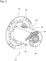
Fig. 3 zeigt die Schlauchtrommel ausFigur 2 in einer perspektivischen Schnittdarstellung.
-
Fig. 1 shows the hose box according to the invention in a schematic perspective view. -
Fig. 2 shows the hose reel inFigure 1 Shown hose box with the meandering guidance of the hose in a schematic perspective view. -
Fig. 3 shows the hose reelFigure 2 in a perspective sectional view.
Für gleiche oder gleichwirkende Elemente der Erfindung werden identische Bezugszeichen verwendet. Ferner werden der Übersicht halber nur Bezugszeichen in den einzelnen Figuren dargestellt, die für die Beschreibung der jeweiligen Figur erforderlich sind. Die dargestellten Ausführungsformen stellen lediglich Beispiele dar, wie die erfindungsgemäße Vorrichtung ausgestaltet sein kann und stellt keine abschließende Begrenzung dar.Identical reference numbers are used for elements of the invention that are the same or have the same effect. Furthermore, for the sake of clarity, only reference numbers that are necessary for the description of the respective figure are shown in the individual figures. The illustrated embodiments merely represent examples of how the device according to the invention can be designed and do not represent a final limitation.
Die
Die Schlauchbox 10 umfasst ein Gehäuse 12, welches aus zumindest zwei Gehäusehälften 14, 14' gebildet ist. Die zumindest zwei Gehäusehälften 14, 14` sind durch hier nicht dargestellte Befestigungsmittel miteinander verbunden. Innerhalb des Gehäuses 12 ist eine um eine Drehachse rotierende Schlauchtrommel 16 vorgesehen. Auf der Schlauchtrommel 16 ist ein Schlauch 32, insbesondere ein Gartenschlauch, (zumindest teilweise in
Das Gehäuse 12 weist einen Montageabschnitt 20 auf, über welchen die Schlauchbox 10 an eine entsprechende Halterung 22, hier in Form einer Wandhalterung, aufgehängt werden kann. Alternativ kann die Schlauchbox 10 auch anderweitig aufgehängt werden, zum Beispiel an einen dafür vorgesehenen Schlauchwagen.The
Um das Tragen und/oder Halten der Schlauchbox 10 zu erleichtern, weist die Schlauchbox 10 am Gehäuse 12 zumindest ein Halte- und/oder Tragelement 24, 24' auf. Das Halte- und/oder Trageelement 24, 24' ist durch einen Traggriff gebildet.In order to make it easier to carry and/or hold the
Das Gehäuse der Schlauchbox umfasst weiterhin einen Montageabschnitt, über welchen die Schlauchbox 10 an eine entsprechende Halterung aufgehängt werden kann.The housing of the hose box further includes a mounting section via which the
Die Schlauchbox 10 umfasst eine hier nicht dargestellte Antriebseinheit, die durch einen Elektromotor gebildet ist. Die Schlauchbox 10 umfasst wenigstens eine Akkupack-Schnittstelle (nicht dargestellt), an welcher ein Akkupack (nicht dargestellt) zur Versorgung der Antriebseinheit mit elektrischer Energie koppelbar ist. Die Akkupack-Schnittstelle und die Antriebseinheit sind über nicht dargestellte Leitungen elektrisch miteinander verbunden.The
Der Akkupack ist als Wechselakkupack ausgebildet, d.h. der Akkupack kann wechselbar sein oder gegen einen anderen Akkupack austauschbar sein. Insbesondere ist der Akkupack als Wechselakkupack bzw. als Systemakkupack ausgebildet; d.h. der Akkupack kann neben der hier vorliegenden Schlauchbox 10 universell zur elektrischen Energieversorgung für verschiedene Elektrogeräte, beispielsweise eines Elektrowerkzeuges, elektrischen Gartengeräts, Haushaltsgeräts, Fahrzeuge oder dergleichen verwendet werden kann.The battery pack is designed as a removable battery pack, i.e. the battery pack can be exchangeable or exchangeable for another battery pack. In particular, the battery pack is designed as a removable battery pack or as a system battery pack; i.e. the battery pack can, in addition to the
Zum Schutz der Akkupack-Schnittstelle und des daran gekoppelten Akkupacks vor Feuchtigkeit, Schmutz, Staub oder dergleichen, ist ein Schutzgehäuse 26 vorgesehen. Innerhalb dieses Schutzgehäuses 26 ist die Akkupack-Schnittstelle angeordnet. Das Schutzgehäuse 26 ist verschwenkbar ausgebildet.A
Der Schlauchbox 10 ist zudem eine Betätigungseinheit 50, beispielsweise in Form eines Schalters, oder Taste oder dergleichen, zugeordnet, mittels welcher die Antriebseinheit angesteuert und ein motorisiertes Aufwickeln des Schlauches 32 auf der Schlauchtrommel 16 durchgeführt wird.The
Um Zugang zur Schlauchtrommel 16 zu erhalten, umfasst das Gehäuse 12 eine Zugangsöffnung mit einem entfernbaren Gehäuseabschnittselement 28. Das Gehäuseabschnittselement 28 ist über hier nicht dargestellte lösbare Klemm- und/oder Schraubverbindungen am Gehäuse 12 befestigt.In order to gain access to the
In den
Die Schlauchtrommel 16 umfasst einen Trommelmantel 30 mit einer zumindest weitgehend zylindrischen Form. An den Stirnseiten des Trommelmantels 30 sind jeweils Trommelscheiben 18 gekoppelt und/oder befestigt. Die Trommelscheiben 18 dienen u.a. dazu, den auf den Trommelmantel 30 aufgewickelten bzw. aufzuwickelnden Schlauch 32 seitlich zu begrenzen.The
Die Trommelscheiben 18 weisen eine Vielzahl von Trommelscheibenöffnungen 34 auf, welche einen eckigen Querschnitt haben. Durch die Vielzahl an Trommelscheibenöffnungen 34 wird das Gewicht der Schlauchtrommel 16 und damit der gesamten Schlauchtrommel 16 verringert.The
Der Trommelmantel 30 umfasst zumindest einen Hohlraum 36, innerhalb welchem ein Kupplungsanschluss 38 vorgesehen ist. Der Kupplungsanschluss 38 ist an einer zum Hohlraum 36 zugewandten Innenseite der Trommelscheibe18 angeordnet. An diesen Kupplungsanschluss 38 ist der Schlauch 32 über ein hier nicht dargestelltes korrespondierendes Kupplungsstück koppelbar. Darüber hinaus ist über hier nicht dargestellte Leitungen der Kupplungsanschluss 38 an einem Wasseranschluss anbindbar.The
In der
Die zumindest zwei Führungselemente 40, 40' können jeweils derart ausgebildet und insbesondere beabstandet zueinander angeordnet sein, so dass der Schlauch 32 zumindest abschnittsweise mäanderförmig um die zumindest zwei Führungselemente 40, 40' geführt und/oder gelegt ist. Die zumindest zwei Führungselemente 40, 40' fungieren zugleich als Zugentlastungselement, da beispielsweise die beim Abwickeln des Schlauchs 32 auftretenden Kräfte nicht mehr direkt auf den Kupplungsanschluss wirken, sondern reduziert werden können.The at least two
Weiterhin ist es aus den
Der zumindest eine Hohlraum 36 ist mittels einer Abdeckung 46 verschließbar und zwar derart, dass die Abdeckung ein Bestandteil des Trommelmantels 30 ist, d.h. die Abdeckung 46 weist die gleiche Wölbung wie der Trommelmantel 30 auf. Die Abdeckung 46 ist beispielsweise über Schraub- und/oder Klemmmittel an dem Trommelmantel 30 zur Abdeckung des zumindest einen Hohlraums 36 befestigbar.The at least one
Bei entfernter Abdeckung 46 und bei entfernten Gehäuseabschnittselement 28 (vgl.
Durch die
- 1010
- SchlauchboxHose box
- 1212
- GehäuseHousing
- 1414
- GehäusehälfteHousing half
- 14'14'
- GehäusehälfteHousing half
- 1616
- SchlauchtrommelHose reel
- 1818
- Trommelscheibendrum discs
- 2020
- MontageabschnittAssembly section
- 2222
- Halterungbracket
- 2424
- Halte- und/oder TragelementHolding and/or supporting element
- 24`24`
- Halte- und/oder TragelementHolding and/or supporting element
- 2626
- SchutzgehäuseProtective housing
- 2828
- GehäuseabschnittselementHousing section element
- 3030
- Trommelmanteldrum shell
- 3232
- SchlauchHose
- 3434
- TrommelscheibenöffnungDrum disc opening
- 3636
- Hohlraumcavity
- 3838
- KupplungsanschlussCoupling connection
- 4040
- FührungselementLeadership element
- 40`40`
- FührungselementLeadership element
- 4242
- Aussparungrecess
- 4444
- weiteres Führungselementanother leadership element
- 4646
- Abdeckungcover
- 4848
- weiterer Hohlraumanother cavity
- 5050
- BetätigungseinheitActuation unit
Claims (10)
Applications Claiming Priority (1)
| Application Number | Priority Date | Filing Date | Title |
|---|---|---|---|
| DE202022101881.2U DE202022101881U1 (en) | 2022-04-07 | 2022-04-07 | hose box |
Publications (1)
| Publication Number | Publication Date |
|---|---|
| EP4257529A1 true EP4257529A1 (en) | 2023-10-11 |
Family
ID=81452718
Family Applications (1)
| Application Number | Title | Priority Date | Filing Date |
|---|---|---|---|
| EP23159672.7A Pending EP4257529A1 (en) | 2022-04-07 | 2023-03-02 | Hose box |
Country Status (2)
| Country | Link |
|---|---|
| EP (1) | EP4257529A1 (en) |
| DE (1) | DE202022101881U1 (en) |
Families Citing this family (1)
| Publication number | Priority date | Publication date | Assignee | Title |
|---|---|---|---|---|
| EP4286311A1 (en) * | 2022-05-31 | 2023-12-06 | Husqvarna AB | Hose reel assembly |
Citations (2)
| Publication number | Priority date | Publication date | Assignee | Title |
|---|---|---|---|---|
| DE202021100427U1 (en) * | 2021-01-28 | 2021-02-08 | Einhell Germany Ag | Hose box |
| EP3812329A1 (en) * | 2019-10-24 | 2021-04-28 | Andreas Stihl AG & Co. KG | Hose drum unit and hose drum assembly comprising a hose drum unit |
-
2022
- 2022-04-07 DE DE202022101881.2U patent/DE202022101881U1/en active Active
-
2023
- 2023-03-02 EP EP23159672.7A patent/EP4257529A1/en active Pending
Patent Citations (2)
| Publication number | Priority date | Publication date | Assignee | Title |
|---|---|---|---|---|
| EP3812329A1 (en) * | 2019-10-24 | 2021-04-28 | Andreas Stihl AG & Co. KG | Hose drum unit and hose drum assembly comprising a hose drum unit |
| DE202021100427U1 (en) * | 2021-01-28 | 2021-02-08 | Einhell Germany Ag | Hose box |
Also Published As
| Publication number | Publication date |
|---|---|
| DE202022101881U1 (en) | 2022-04-20 |
Similar Documents
| Publication | Publication Date | Title |
|---|---|---|
| DE102017119466B4 (en) | Device for storing electrical energy for a motor vehicle | |
| EP1921717B1 (en) | Assembly set for an electrical socket | |
| EP4257529A1 (en) | Hose box | |
| EP2819207B1 (en) | Combination of a support system, battery and driven device | |
| EP2186099B1 (en) | Cable harness production system | |
| US6497133B1 (en) | Cable cutter and bender | |
| DE102012205414B3 (en) | Electrically powered vehicle has removable traction battery that is arranged in underbody-sided constructed space, where transmission unit is provided for fixed interlocking of traction battery in underbody-sided constructed space | |
| DE202021100429U1 (en) | Hose box arrangement | |
| EP3678214A1 (en) | Structure, battery pack and gardening and/or forestry system | |
| EP3678216B1 (en) | Battery pack and gardening and/or forestry system | |
| DE4118334A1 (en) | BATTERY CABLE CONNECTOR | |
| DE7926920U1 (en) | SUPPLY DEVICE FOR THE ELECTRICAL SUPPLY OF HAND TOOLS OR WORK EQUIPMENT DRIVEN BY AN ELECTRIC MOTOR, IN PARTICULAR LAWN EDGE CUTTERS | |
| DE10013938C1 (en) | Mains connection for emergency vehicle battery recharging has dished housing and cooperating pivoted cover supporting plug-in connection | |
| EP2135333B1 (en) | Extension cable for electrical pipe processing devices | |
| DE202021100427U1 (en) | Hose box | |
| DE102006054374B4 (en) | Device for removing ice and snow from power lines | |
| DE102019115526A1 (en) | Electric distribution box | |
| CN211428563U (en) | Multifunctional wire stripper for electric wire | |
| DE102008006469A1 (en) | Device i.e. tool case or transport box, for storing and transporting e.g. power tool, has multi-conductor cable for current supply of tool or accessory, and connected to connector and arranged in sections inside case | |
| DE10019459C1 (en) | Cable drum with extendable cable sections | |
| EP0402635B1 (en) | Device for the connection of a battery pole to at least one connecting cable | |
| DE102010005425A1 (en) | Plug socket for trailer coupling device for supplying current to trailer for motor vehicle, has plug contacts accessed via opening that is covered by hinged cover, where hinged cover possesses surface that is larger than opening | |
| EP2449933A1 (en) | Vacuum cleaner with a cable holder | |
| DE202019000189U1 (en) | Pillar for providing electricity | |
| AT521834B1 (en) | Winding device for data cables |
Legal Events
| Date | Code | Title | Description |
|---|---|---|---|
| PUAI | Public reference made under article 153(3) epc to a published international application that has entered the european phase |
Free format text: ORIGINAL CODE: 0009012 |
|
| STAA | Information on the status of an ep patent application or granted ep patent |
Free format text: STATUS: THE APPLICATION HAS BEEN PUBLISHED |
|
| AK | Designated contracting states |
Kind code of ref document: A1 Designated state(s): AL AT BE BG CH CY CZ DE DK EE ES FI FR GB GR HR HU IE IS IT LI LT LU LV MC ME MK MT NL NO PL PT RO RS SE SI SK SM TR |
|
| STAA | Information on the status of an ep patent application or granted ep patent |
Free format text: STATUS: REQUEST FOR EXAMINATION WAS MADE |
|
| 17P | Request for examination filed |
Effective date: 20240404 |
|
| RBV | Designated contracting states (corrected) |
Designated state(s): AL AT BE BG CH CY CZ DE DK EE ES FI FR GB GR HR HU IE IS IT LI LT LU LV MC ME MK MT NL NO PL PT RO RS SE SI SK SM TR |