EP4257482B1 - Schaufelanordnung mit strukturell verstärktem schaumstoffkern - Google Patents
Schaufelanordnung mit strukturell verstärktem schaumstoffkern Download PDFInfo
- Publication number
- EP4257482B1 EP4257482B1 EP23164443.6A EP23164443A EP4257482B1 EP 4257482 B1 EP4257482 B1 EP 4257482B1 EP 23164443 A EP23164443 A EP 23164443A EP 4257482 B1 EP4257482 B1 EP 4257482B1
- Authority
- EP
- European Patent Office
- Prior art keywords
- airfoil
- foam
- airfoil assembly
- structural support
- support members
- Prior art date
- Legal status (The legal status is an assumption and is not a legal conclusion. Google has not performed a legal analysis and makes no representation as to the accuracy of the status listed.)
- Active
Links
Images


Classifications
-
- B—PERFORMING OPERATIONS; TRANSPORTING
- B64—AIRCRAFT; AVIATION; COSMONAUTICS
- B64C—AEROPLANES; HELICOPTERS
- B64C11/00—Propellers, e.g. of ducted type; Features common to propellers and rotors for rotorcraft
- B64C11/16—Blades
- B64C11/20—Constructional features
- B64C11/26—Fabricated blades
-
- F—MECHANICAL ENGINEERING; LIGHTING; HEATING; WEAPONS; BLASTING
- F01—MACHINES OR ENGINES IN GENERAL; ENGINE PLANTS IN GENERAL; STEAM ENGINES
- F01D—NON-POSITIVE DISPLACEMENT MACHINES OR ENGINES, e.g. STEAM TURBINES
- F01D5/00—Blades; Blade-carrying members; Heating, heat-insulating, cooling or antivibration means on the blades or the members
- F01D5/12—Blades
- F01D5/14—Form or construction
- F01D5/147—Construction, i.e. structural features, e.g. of weight-saving hollow blades
-
- F—MECHANICAL ENGINEERING; LIGHTING; HEATING; WEAPONS; BLASTING
- F04—POSITIVE - DISPLACEMENT MACHINES FOR LIQUIDS; PUMPS FOR LIQUIDS OR ELASTIC FLUIDS
- F04D—NON-POSITIVE-DISPLACEMENT PUMPS
- F04D29/00—Details, component parts, or accessories
- F04D29/02—Selection of particular materials
- F04D29/023—Selection of particular materials especially adapted for elastic fluid pumps
-
- F—MECHANICAL ENGINEERING; LIGHTING; HEATING; WEAPONS; BLASTING
- F04—POSITIVE - DISPLACEMENT MACHINES FOR LIQUIDS; PUMPS FOR LIQUIDS OR ELASTIC FLUIDS
- F04D—NON-POSITIVE-DISPLACEMENT PUMPS
- F04D29/00—Details, component parts, or accessories
- F04D29/26—Rotors specially for elastic fluids
- F04D29/32—Rotors specially for elastic fluids for axial flow pumps
- F04D29/321—Rotors specially for elastic fluids for axial flow pumps for axial flow compressors
- F04D29/324—Blades
-
- F—MECHANICAL ENGINEERING; LIGHTING; HEATING; WEAPONS; BLASTING
- F04—POSITIVE - DISPLACEMENT MACHINES FOR LIQUIDS; PUMPS FOR LIQUIDS OR ELASTIC FLUIDS
- F04D—NON-POSITIVE-DISPLACEMENT PUMPS
- F04D29/00—Details, component parts, or accessories
- F04D29/40—Casings; Connections of working fluid
- F04D29/52—Casings; Connections of working fluid for axial pumps
- F04D29/54—Fluid-guiding means, e.g. diffusers
- F04D29/541—Specially adapted for elastic fluid pumps
- F04D29/542—Bladed diffusers
-
- B—PERFORMING OPERATIONS; TRANSPORTING
- B64—AIRCRAFT; AVIATION; COSMONAUTICS
- B64D—EQUIPMENT FOR FITTING IN OR TO AIRCRAFT; FLIGHT SUITS; PARACHUTES; ARRANGEMENT OR MOUNTING OF POWER PLANTS OR PROPULSION TRANSMISSIONS IN AIRCRAFT
- B64D27/00—Arrangement or mounting of power plants in aircraft; Aircraft characterised by the type or position of power plants
- B64D2027/005—Aircraft with an unducted turbofan comprising contra-rotating rotors, e.g. contra-rotating open rotors [CROR]
-
- F—MECHANICAL ENGINEERING; LIGHTING; HEATING; WEAPONS; BLASTING
- F05—INDEXING SCHEMES RELATING TO ENGINES OR PUMPS IN VARIOUS SUBCLASSES OF CLASSES F01-F04
- F05D—INDEXING SCHEME FOR ASPECTS RELATING TO NON-POSITIVE-DISPLACEMENT MACHINES OR ENGINES, GAS-TURBINES OR JET-PROPULSION PLANTS
- F05D2230/00—Manufacture
- F05D2230/10—Manufacture by removing material
-
- F—MECHANICAL ENGINEERING; LIGHTING; HEATING; WEAPONS; BLASTING
- F05—INDEXING SCHEMES RELATING TO ENGINES OR PUMPS IN VARIOUS SUBCLASSES OF CLASSES F01-F04
- F05D—INDEXING SCHEME FOR ASPECTS RELATING TO NON-POSITIVE-DISPLACEMENT MACHINES OR ENGINES, GAS-TURBINES OR JET-PROPULSION PLANTS
- F05D2230/00—Manufacture
- F05D2230/50—Building or constructing in particular ways
-
- F—MECHANICAL ENGINEERING; LIGHTING; HEATING; WEAPONS; BLASTING
- F05—INDEXING SCHEMES RELATING TO ENGINES OR PUMPS IN VARIOUS SUBCLASSES OF CLASSES F01-F04
- F05D—INDEXING SCHEME FOR ASPECTS RELATING TO NON-POSITIVE-DISPLACEMENT MACHINES OR ENGINES, GAS-TURBINES OR JET-PROPULSION PLANTS
- F05D2250/00—Geometry
- F05D2250/20—Three-dimensional
- F05D2250/28—Three-dimensional patterned
- F05D2250/283—Three-dimensional patterned honeycomb
-
- F—MECHANICAL ENGINEERING; LIGHTING; HEATING; WEAPONS; BLASTING
- F05—INDEXING SCHEMES RELATING TO ENGINES OR PUMPS IN VARIOUS SUBCLASSES OF CLASSES F01-F04
- F05D—INDEXING SCHEME FOR ASPECTS RELATING TO NON-POSITIVE-DISPLACEMENT MACHINES OR ENGINES, GAS-TURBINES OR JET-PROPULSION PLANTS
- F05D2300/00—Materials; Properties thereof
- F05D2300/60—Properties or characteristics given to material by treatment or manufacturing
- F05D2300/612—Foam
Definitions
- the present disclosure relates to airfoil assemblies and methods for manufacturing the same.
- a gas turbine engine typically includes a fan assembly and a turbomachine.
- the turbomachine generally includes an inlet, one or more compressors, a combustor, and at least one turbine.
- the compressors compress air which is channeled to the combustor where it is mixed with fuel. The mixture is then ignited for generating hot combustion gases.
- the combustion gases are channeled to the turbine(s) which extracts energy from the combustion gases for powering the compressor(s), as well as for producing useful work to propel an aircraft in flight or to power a load, such as an electrical generator.
- the fan assembly generally includes a fan having a plurality of airfoils or fan blades extending radially outwardly from a central hub and/or a disk.
- US5634771A discloses a lightweight, impact-resistant gas turbine blade, such as an aircraft engine fan blade, which has a metal solid section, composite or structural/syntactic foam segments, and metal solid spars all attached together to define an airfoil portion.
- the solid section includes the leading edge, blade tip, and trailing edge.
- the segments together are bounded in part by the solid section near the leading edge, blade tip, and trailing edge.
- the solid spars separate and are attached to the segments.
- the terms “first,” “second,” and “third” may be used interchangeably to distinguish one component from another and are not intended to signify location or importance of the individual components.
- the terms “includes” and “including” are intended to be inclusive in a manner similar to the term “comprising.”
- the term “or” is generally intended to be inclusive (i.e., “A or B” is intended to mean “A or B or both”).
- the term “at least one of” in the context of, e.g., “at least one of A, B, and C” refers to only A, only B, only C, or any combination of A, B, and C.
- range limitations may be combined and/or interchanged.
- Approximating language may be applied to modify any quantitative representation that could permissibly vary without resulting in a change in the basic function to which it is related. Accordingly, a value modified by a term or terms, such as “generally,” “about,” “approximately,” and “substantially,” are not to be limited to the precise value specified.
- the approximating language may correspond to the precision of an instrument for measuring the value, or the precision of the methods or machines for constructing or manufacturing the components and/or systems.
- the approximating language may refer to being within a 10 percent margin, i.e., including values within ten percent greater or less than the stated value. In this regard, for example, when used in the context of an angle or direction, such terms include within ten degrees greater or less than the stated angle or direction.
- forward and aft refer to relative positions within a gas turbine engine or vehicle, and refer to the normal operational attitude of the gas turbine engine or vehicle. For example, with regard to a gas turbine engine, forward refers to a position closer to an engine inlet and aft refers to a position closer to an engine nozzle or exhaust.
- upstream and downstream refer to the relative direction with respect to fluid flow in a fluid pathway. For example, “upstream” refers to the direction from which the fluid flows, and “downstream” refers to the direction to which the fluid flows.
- first stream or “free stream” refers to a stream that flows outside of the engine inlet and over a fan, which is unducted. Furthermore, the first stream is a stream of air that is free stream air.
- second stream or “core stream” refers to a stream that flows through the engine inlet and the ducted fan and also travels through the core inlet and the core duct.
- third stream or “mid-fan stream” refers to a stream that flows through an engine inlet and a ducted fan but does not travel through a core inlet and a core duct. Furthermore, the third stream is a stream of air that takes inlet air as opposed to free stream air. The third stream goes through at least one stage of the turbomachine, e.g., the ducted fan.
- a third stream means a non-primary air stream capable of increasing fluid energy to produce a minority of total propulsion system thrust.
- a pressure ratio of the third stream is higher than that of the primary propulsion stream (e.g., a bypass or propeller driven propulsion stream).
- the thrust may be produced through a dedicated nozzle or through mixing of an airflow through the third stream with a primary propulsion stream or a core air stream, e.g., into a common nozzle.
- an operating temperature of the airflow through the third stream may be less than a maximum compressor discharge temperature for the engine, and more specifically may be less than 177 degrees Celsius (350 degrees Fahrenheit) (such as less than 149 degrees Celsius (300 degrees Fahrenheit), such as less than 121 degrees Celsius (250 degrees Fahrenheit), such as less than 93 degrees Celsius (200 degrees Fahrenheit), and at least as great as an ambient temperature). In certain exemplary embodiments, these operating temperatures may facilitate heat transfer to or from the airflow through the third stream and a separate fluid stream.
- the airflow through the third stream may contribute less than 50% of the total engine thrust (and at least, e.g., 2% of the total engine thrust) at a takeoff condition, or more particularly while operating at a rated takeoff power at sea level, static flight speed, 86 degrees Fahrenheit ambient temperature operating conditions. In other exemplary embodiments, it is contemplated that the airflow through the third stream may contribute greater than 50% of the total engine thrust (and at least, e.g., 2% of the total engine thrust) at an engine operating condition. In other exemplary embodiments, it is contemplated that the airflow through the third stream may contribute approximately 50% of the total engine thrust (and at least, e.g., 2% of the total engine thrust) at an engine operating condition.
- aspects of the airflow through the third stream may passively adjust during engine operation or be modified purposefully through use of engine control features (such as fuel flow, electric machine power, variable stators, variable inlet guide vanes, valves, variable exhaust geometry, or fluidic features) to adjust or optimize overall system performance across a broad range of potential operating conditions.
- engine control features such as fuel flow, electric machine power, variable stators, variable inlet guide vanes, valves, variable exhaust geometry, or fluidic features
- Certain modem fan blades are formed of composite material(s) to reduce a weight of the fan blades.
- aircraft engine components such as fan blades, nacelles, guide vanes, etc., used in jet engine applications are susceptible to foreign object impact damage or ingestion events, such as an ice ingestion or bird strike.
- fan blades formed from composite material(s) may be more susceptible to damage in such events, e.g., by blade fracture, component delamination, bending or deformation damage, or other forms of blade damage. Accordingly, improved airfoil designs for addressing one or more of the above-mentioned problems would be useful. More specifically, an airfoil assembly with a lightweight and structurally sound design that can withstand foreign object ingestion events would be particularly beneficial.
- composite fan blades that use internal foam support may be used in gas turbine engines.
- the foam may have a high risk of debonding from other portions of the blade. More specifically, under certain operational loads or during an ingestion event (e.g., ice ingestion or bird strike), the foam within a composite blade may shear or otherwise lose its bond with the spar, the outer blade skin, etc. Accordingly, aspects of the present subject matter are generally directed to a structurally reinforced foam positioned within the composite blade, e.g., within a void defined between a spar and an outer blade skin.
- the foam may be segmented and placed at different regions of the blade to meet the strength and stiffness requirements of the blade.
- the structural reinforcement may include a frame, grid, cross members, elongated supports, etc. that are formed from chopped fiber polymer matrix composites ("PMCs"), continuous PMCs, glass, sheet metal, etc.
- PMCs chopped fiber polymer matrix composites
- the structurally reinforced foam may be co-cured to generate a bond line between the structural spar and blade flowpath skins.
- Such a composite blade construction may facilitate improved foam durability, thus enabling fan blade weight reduction while minimizing the potential for blade deformation, debonding, failure, or other operational degradation.
- local blade stiffnesses may be modified and tailored by selectively designing and positioning structural reinforcements within the foam.
- such constructions may improve fan blade stability to meet aeromechanical requirements, may result in an improvement in dissipation of shock wave energy due to impact loads, may provided better control of blade untwist behavior to improve the operability margins, may improve fan blade durability, etc.
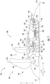
- FIG. 1 a schematic cross-sectional view of a gas turbine engine 100 is provided according to an example embodiment of the present disclosure.
- FIG. 1 provides an engine having a rotor assembly with a single stage of unducted rotor blades.
- the rotor assembly may be referred to herein as an "unducted fan,” or the entire gas turbine engine 100 may be referred to as an "unducted engine,” or an engine having an open rotor propulsion system 102.
- the engine of FIG. 1 includes a mid-fan stream extending from the compressor section to a rotor assembly flowpath over the turbomachine, as will be explained in more detail below.
- the present disclosure is compatible with an engine having a duct around the unducted fan. It is also contemplated that, in other exemplary embodiments, the present disclosure is compatible with a turbofan engine having a third stream as described herein.
- the gas turbine engine 100 defines an axial direction A, a radial direction R, and a circumferential direction C. Moreover, the gas turbine engine 100 defines an axial centerline or longitudinal axis 112 that extends along the axial direction A.
- the axial direction A extends parallel to the longitudinal axis 112
- the radial direction R extends outward from and inward to the longitudinal axis 112 in a direction orthogonal to the axial direction A
- the circumferential direction extends three hundred sixty degrees (360°) around the longitudinal axis 112.
- the gas turbine engine 100 extends between a forward end 114 and an aft end 116, e.g., along the axial direction A.
- the gas turbine engine 100 includes a turbomachine 120, also referred to as a core of the gas turbine engine 100, and a rotor assembly, also referred to as a fan section 150, positioned upstream thereof.
- the turbomachine 120 includes, in serial flow order, a compressor section, a combustion section, a turbine section, and an exhaust section.
- the turbomachine 120 includes a core cowl 122 that defines an annular core inlet 124.
- the core cowl 122 further encloses at least in part a low pressure system and a high pressure system.
- the core cowl 122 depicted encloses and supports at least in part a booster or low pressure (“LP”) compressor 126 for pressurizing the air that enters the turbomachine 120 through core inlet 124.
- LP booster or low pressure
- a high pressure (“HP"), multi-stage, axial-flow compressor 128 receives pressurized air from the LP compressor 126 and further increases the pressure of the air.
- the pressurized air stream flows downstream to a combustor 130 of the combustion section where fuel is injected into the pressurized air stream and ignited to raise the temperature and energy level of the pressurized air and produce high energy combustion products.
- the high energy combustion products flow from the combustor 130 downstream to a high pressure turbine 132.
- the high pressure turbine 132 drives the high pressure compressor 128 through a high pressure shaft 136.
- the high pressure turbine 132 is drivingly coupled with the high pressure compressor 128.
- the high energy combustion products then flow to a low pressure turbine 134.
- the low pressure turbine 134 drives the low pressure compressor 126 and components of the fan section 150 through a low pressure shaft 138.
- the low pressure turbine 134 is drivingly coupled with the low pressure compressor 126 and components of the fan section 150.
- the LP shaft 138 is coaxial with the HP shaft 136 in this example embodiment.
- the turbomachine 120 defines a working gas flowpath or core duct 142 that extends between the core inlet 124 and the turbomachine exhaust nozzle 140.
- the core duct 142 is an annular duct positioned generally inward of the core cowl 122 along the radial direction R.
- the core duct 142 (e.g., the working gas flowpath through the turbomachine 120) may be referred to as a second stream.
- the fan section 150 includes a fan 152, which is the primary fan in this example embodiment.
- the fan 152 is an open rotor or unducted fan 152.
- the fan 152 includes an array of fan blades 154 (only one shown in FIG. 1 ).
- the fan blades 154 are rotatable, e.g., about the longitudinal axis 112.
- the fan 152 is drivingly coupled with the low pressure turbine 134 via the LP shaft 138.
- the fan 152 can be directly coupled with the LP shaft 138, e.g., in a direct-drive configuration.
- the fan 152 is coupled with the LP shaft 138 via a speed reduction gearbox 155, e.g., in an indirect-drive or geared-drive configuration.
- each fan blade 154 can be arranged in equal spacing around the longitudinal axis 112.
- Each fan blade 154 has a root and a tip and a span defined therebetween.
- Each fan blade 154 defines a central blade axis 156.
- each fan blade 154 of the fan 152 is rotatable about their respective central blade axis 156, e.g., in unison with one another.
- One or more actuators 158 are provided to facilitate such rotation and therefore may be used to change a pitch the fan blades 154 about their respective central blade axis 156.
- the fan section 150 further includes a fan guide vane array 160 that includes fan guide vanes 162 (only one shown in FIG. 1 ) disposed around the longitudinal axis 112.
- the fan guide vanes 162 are not rotatable about the longitudinal axis 112.
- Each fan guide vane 162 has a root and a tip and a span defined therebetween.
- the fan guide vanes 162 may be unshrouded as shown in FIG. 1 or, alternatively, may be shrouded, e.g., by an annular shroud spaced outward from the tips of the fan guide vanes 162 along the radial direction R or attached to the fan guide vanes 162.
- Each fan guide vane 162 defines a central blade axis 164.
- each fan guide vane 162 of the fan guide vane array 160 is rotatable about their respective central blade axis 164, e.g., in unison with one another.
- One or more actuators 166 are provided to facilitate such rotation and therefore may be used to change a pitch of the fan guide vane 162 about their respective central blade axis 164.
- each fan guide vane 162 may be fixed or unable to be pitched about its central blade axis 164.
- the fan guide vanes 162 are mounted to a fan cowl 170.
- the fan cowl 170 annularly encases at least a portion of the core cowl 122 and is generally positioned outward of at least a portion of the core cowl 122 along the radial direction R. Particularly, a downstream section of the fan cowl 170 extends over a forward portion of the core cowl 122 to define a fan flowpath or fan duct 172.
- the fan flowpath or fan duct 172 may be referred to as a third stream of the gas turbine engine 100.
- the fan duct 172 and the core duct 142 may at least partially co-extend (generally axially) on opposite sides (e.g., opposite radial sides) of the core cowl 122.
- the fan duct 172 and the core duct 142 may each extend directly from a leading edge 144 of the core cowl 122 and may partially co-extend generally axially on opposite radial sides of the core cowl.
- thermoplastic resins that have been contemplated for use in aerospace applications include, polyetheretherketone (PEEK), polyetherketoneketone (PEKK), polyetherimide (PEI), polyaryletherketone (PAEK), and polyphenylene sulfide (PPS).
- PEEK polyetheretherketone
- PEKK polyetherketoneketone
- PEI polyetherimide
- PAEK polyaryletherketone
- PPS polyphenylene sulfide
- thermoset resins include epoxy, bismaleimide (BMI), and polyimide resins.
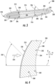
- foam reinforcement structure 242 includes a plurality of structural support members 244 that extend through foam 240 and which have any suitable geometry, angle, and spacing for improving the rigidity are structural integrity of airfoil assembly 200.
- each of the plurality of structural support members 244 is substantially straight or planar and extends between leading edge 218 of airfoil 212 to an upstream edge 246 of central spar 202.
- structural support members 244 may additionally extend between a downstream edge 248 of central spar 202 and trailing edge 220 of airfoil 212.
- structure thickness 261 is between 0.0051 and 0.127 cm (0.002 and 0.05 inches), between 0.008 and 0.102 cm (0.003 and 0.04 inches), between 0.015 and 0.051 cm (0.006 and 0.02 inches), or about 0.033 cm (0.013 inches). Other spacings and structure sizes are possible and within the scope present subject matter.
- foam reinforcement structure 242 may have any suitable geometry or structure.
- foam reinforcement structure 242 includes a plurality of linear structural support members 244.
- structural support members 244 may be curved, serpentine, or may have any other suitable size and/or geometry depending on the application.
- foam reinforcement structure 242 may further include a honeycomb structure (e.g., as identified generally by reference numeral 262), a cellular matrix structure (e.g., as identified generally by reference numeral 264), or any other suitable grid, lattice, or mesh-like structure.
- the specific geometry selected for foam reinforcement structure 242 may vary depending on the location within airfoil assembly 200.
- each region 250 of airfoil 212 may include a foam reinforcement structure 242 that is similar to or different that other regions 250 of the same airfoil 212.
- one region 250 may include structural support members 244, another may include a honeycomb structure 262, and still another may include a cellular matrix.
- the spacing 260 and structure thickness 261 may vary among regions 250. Indeed, it should be appreciated that any and all of the foam reinforcement structures 242 and their variations described herein may not be mutually exclusive and may be utilized in a single airfoil as desired depending on the application.
- structural support members 244 may include a flared end 270 that contacts blade skin 210.
- a thickness of each structural support member 244 may increase toward a contact point with blade skin 210 to provide improved physical connection or load distribution between the blade skin 210 and structural support member 244.
- Other geometry variations are possible and within the scope of the present subject matter.
- airfoil assembly 200 may include an adhesive 272 that is positioned on the inside of blade skin 210 and/or on central spar 202 for improving the structural engagement between portions of airfoil assembly 200.
- adhesive 272 may be positioned between support structure 232 and at least one of central spar 202 or blade skin 210.
- Adhesives may include epoxy, polyurethane, or any other kind of adhesive known to those of ordinary skill in the art.
- airfoil assembly 200 may include additional structural supports for improving the rigidity of airfoil assembly 200.
- airfoil assembly 200 may include a leading edge structural support 274 and a trailing edge structural support 276.
- leading edge structural support 274 may be positioned between blade skin 210 and support structure 232 proximate leading edge 218 of airfoil 212.
- trailing edge structural support 276 may be positioned between blade skin 210 and support structure 232 proximate trailing edge 220 of airfoil 212.
- leading edge structural support 274 and trailing edge structural support 276 may be spaced apart from central spar 202 along a chordwise direction to define a plurality of cavities 230 filled with support structure 232.
- leading edge structural support 274 and trailing edge structural support 276 may be separate from central spar 202 or may be mechanically coupled to central spar 202, e.g., proximate root 206 of airfoil 212.
- foam reinforcement structure 242 may further include one or more foam engagement structures 280 that are positioned on or extend from blade skin 210 and into cavities 230 when blade skin 210 is wrapped around central spar 202 and support structure 232.
- foam engagement structures 280 may include one or more protruding members 282 or tapered lugs 284.
- airfoil 212 may generally define a blade thickness 286 measured normal to a chordwise direction.
- foam engagement structures 280 extend across only a portion of blade thickness 286.
- foam engagement structures 280 may extend less than half, less than a quarter, or less, through blade thickness 286.
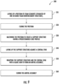
- method 300 may be used to construct airfoil assembly 200 as described above.
- aspects of method 300 may be applied to the construction of any other suitable airfoil.
- alterations and modifications may be made to method 300 while remaining within scope of the present subject matter.
- Method 300 includes, at step 310, laying of a preform of foam segments separated by one or more foam reinforcement structures.
- a plurality of solid foam blocks may be formed which have the desired dimensions, e.g., such as a rectangular cross-section with a thickness equivalent to a target spacing between adjacent reinforcement structures.
- the foam reinforcement structures may be separately manufactured or acquired for providing additional structure support within the foam blocks.
- the foam segments may be alternately stacked with the foam reinforcement structure to create a preform.
- an adhesive or bonding agent may be applied to one or both the foam segments and the foam reinforcement structures for improved engagement between the two.
- the adhesive may then be allowed to dry to generate the support structure preform.
- step 320 may include curing the preform to cure the adhesive, improve the bond between the foam segments and the foam reinforcement structure, and create a solid support structure that includes both foam segments and foam reinforcement structures.
- steps 310 and 320 may result in a support structure preform that does not have a suitable shape to be the base of an airfoil. Accordingly, if the preform does not have the desired airfoil shape, it may be desirable to machine or manipulate the preform to have a profile suitable for forming an airfoil, e.g., upon assembly and skin wrapping. Accordingly, step 330 may include machining the preform to create a support structure having a predetermined core profile. In this regard, for example, the resulting support structure may have the shape of the cavities defined between a central spar and blade skin.
- Step 340 includes laying up the support structure against a central spar.
- an adhesive or bonding agent may be applied between the support structure and the central spar to create the internal structure of airfoil assembly.
- Step 350 includes wrapping the support structure and the central spar with a blade skin to form an airfoil assembly.
- an adhesive may be used on the surface of the blade skin that contacts the support structure and/or the central spar.
- Step 360 then includes curing the airfoil assembly to bond all components of airfoil assembly together.
- airfoil assemblies may be constructed by assembling the central spar, blade skin, and support structures prior to injecting a foam filler.
- the support structure and other portions of airfoil assemblies may be constructed in any suitable manner, e.g., such as via additive manufacturing or other methods. Other suitable methods for manufacturing airfoil assemblies as described herein are possible and within scope of the present subject matter.
- FIG. 9 depicts steps performed in a particular order for purposes of illustration and discussion. Those of ordinary skill in the art, using the disclosures provided herein, will understand that the steps of any of the methods discussed herein can be adapted, rearranged, expanded, omitted, or modified in various ways without deviating from the scope of the present disclosure. Moreover, although aspects of method 300 are explained using airfoil assembly 200 as an example, it should be appreciated that this method may be applied to the construction of any other suitable airfoil for any other suitable application.
Landscapes
- Engineering & Computer Science (AREA)
- Mechanical Engineering (AREA)
- General Engineering & Computer Science (AREA)
- Architecture (AREA)
- Aviation & Aerospace Engineering (AREA)
- Structures Of Non-Positive Displacement Pumps (AREA)
Claims (14)
- Schaufelblattanordnung (200), umfassend:einen zentralen Holm (202), der sich entlang einer ersten Richtung (R) erstreckt;eine Laufschaufelhaut (210), die um den zentralen Holm (202) positioniert ist, um ein Schaufelblatt (212), das eine Druckseite (214) und eine Saugseite (216) aufweist, zu definieren, die sich in eine zweite Richtung (A) erstrecken, wobei die zweite Richtung (A) zu der ersten Richtung (R) senkrecht ist, wobei sich die Druckseite und die Saugseite zwischen einer Vorderkante (218) und einer Hinterkante (220) erstrecken, wobei zwischen der Laufschaufelhaut (210) und dem zentralen Holm (202) mindestens ein Hohlraum (230) definiert ist; undeine Stützstruktur (232), die mindestens teilweise innerhalb des mindestens einen Hohlraums (230) positioniert ist, die Stützstruktur (232) umfassend:einen Schaum (240); undeine Schaumverstärkungsstruktur (242), die innerhalb des Schaums (240) eingebettet ist, dadurch gekennzeichnet, dass die Schaumverstärkungsstruktur (242) eine Vielzahl von Strukturstützelementen (244) umfasst, und wobei sich mindestens eines der Vielzahl von Strukturstützelementen (244) zwischen der Vorderkante (218) des Schaufelblatts (212) und einer stromaufwärtigen Kante (246) des zentralen Holms (202) oder zwischen einer stromabwärtigen Kante (248) des zentralen Holms (202) und der Hinterkante (220) des Schaufelblatts (212) erstreckt.
- Schaufelblattanordnung (200) nach Anspruch 1, wobei sich das mindestens eine der Vielzahl von Strukturstützelementen (244) in einem ersten Winkel (252), gemessen relativ zu der zweiten Richtung (A), erstreckt, wobei der erste Winkel (252) zwischen 30 und 65 Grad beträgt.
- Schaufelblattanordnung (200) nach einem der vorstehenden Ansprüche, wobei sich mindestens eines der Vielzahl von Strukturstützelementen (244) zwischen der Druckseite (214) und der Saugseite (216) des Schaufelblatts (212) zusätzlich erstreckt.
- Schaufelblattanordnung (200) nach Anspruch 3, wobei sich das mindestens eine der Vielzahl von Strukturstützelementen (244) in einem zweiten Winkel (256), gemessen relativ zu der Druckseite (214) des Schaufelblatts (212), erstreckt, wobei der zweite Winkel (256) 90 Grad beträgt.
- Schaufelblattanordnung (200) nach Anspruch 3, wobei sich das mindestens eine der Vielzahl von Strukturstützelementen (244) in einem zweiten Winkel (256), gemessen relativ zu der Druckseite (214) des Schaufelblatts (212), erstreckt, wobei der zweite Winkel (256) größer als 75 Grad und kleiner als 90 Grad beträgt.
- Schaufelblattanordnung (200) nach einem der vorstehenden Ansprüche, wobei sich die Schaufelblattanordnung (200) entlang der ersten Richtung zwischen einem Fuß (206) und einer Spitze (208) erstreckt, um eine Spannweitenrichtung zu definieren, und wobei ein Abstand (260) zwischen der Vielzahl von Strukturstützelementen (244) entlang der Spannweitenrichtung variiert, wobei der Abstand (260) zwischen der Vielzahl von Strukturstützelementen (244) zwischen 1,27 und 5,08 cm (0,5 und 2 Zoll) beträgt.
- Schaufelblattanordnung (200) nach Anspruch 6, wobei jedes der Vielzahl von Strukturstützelementen (244) eine Strukturdicke (261) definiert, und wobei die Strukturdicke (261) zwischen 0,1524 und 0,508 mm (0,006 und 0,02 Zoll) beträgt.
- Schaufelblattanordnung (200) nach einem der vorstehenden Ansprüche, wobei mindestens eines der Vielzahl von Strukturstützelementen (244) ein aufgeweitetes Ende (270), das die Laufschaufelhaut (210) berührt, umfasst.
- Schaufelblattanordnung (200) nach einem der vorstehenden Ansprüche, wobei die Schaumverstärkungsstruktur (242) eine Waben- (262) oder Zellmatrix(264)-Struktur umfasst.
- Schaufelblattanordnung (200) nach einem der vorstehenden Ansprüche, wobei die Stützstruktur (232) eine Vielzahl von Regionen (250) definiert, wobei die Schaumverstärkungsstruktur (242) in mindestens zwei der Vielzahl von Regionen (250) eine andere Geometrie oder ein anderes Material besitzt.
- Schaufelblattanordnung (200) nach einem der vorstehenden Ansprüche, wobei die Schaumverstärkungsstruktur (242) ferner umfasst:
eine oder mehrere Schaum(240)-Eingriffsstrukturen, die auf der Laufschaufelhaut (210) positioniert sind und sich in den mindestens einen Hohlraum (230) hineinerstrecken, wenn die Laufschaufelhaut (210) um den zentralen Holm (202) positioniert ist. - Schaufelblattanordnung (200) nach einem der vorstehenden Ansprüche, wobei der Schaum (240) mindestens einen von einem Schaum aus Polymethacrylimid (PMI), einem Urethanschaum oder einem gegossenen synthetischen Schaum umfasst.
- Schaufelblattanordnung (200) nach einem der vorstehenden Ansprüche, wobei die Schaumverstärkungsstruktur (242) mindestens eines von einem Polymermatrix-Verbundwerkstoff, metallischen Verstärkungen, Kohlenstoffverstärkungen, thermoplastischen Kunststoffen oder Glas umfasst.
- Verfahren (300) zum Herstellen einer Schaufelblattanordnung, das Verfahren (300) umfassend:Schichten eines Vorformlings aus Schaumsegmenten, die durch eine oder mehrere Schaumverstärkungsstrukturen (310) getrennt sind;Bearbeiten des Vorformlings, um eine Stützstruktur, die ein vorgegebenes Kernprofil (330) aufweist, zu schaffen;Schichten der Stützstruktur gegen einen zentralen Holm (340);Positionieren einer Laufschaufelhaut um die Stützstruktur und den zentralen Holm, um die Schaufelblattanordnung (350) zu bilden;Aushärten der Schaufelblattanordnung (360); undwobei die Schaumverstärkungsstruktur eine Vielzahl von Strukturstützelementen umfasst, und wobei sich mindestens eines der Vielzahl von Strukturstützelementen zwischen der Vorderkante des Schaufelblatts und einer stromaufwärtigen Kante des zentralen Holms oder zwischen einer stromabwärtigen Kante des zentralen Holms und der Hinterkante des Schaufelblatts erstreckt.
Applications Claiming Priority (1)
| Application Number | Priority Date | Filing Date | Title |
|---|---|---|---|
| US17/712,701 US11795827B1 (en) | 2022-04-04 | 2022-04-04 | Airfoil assembly with a structurally reinforced foam core |
Publications (3)
| Publication Number | Publication Date |
|---|---|
| EP4257482A1 EP4257482A1 (de) | 2023-10-11 |
| EP4257482B1 true EP4257482B1 (de) | 2024-11-27 |
| EP4257482B8 EP4257482B8 (de) | 2025-01-01 |
Family
ID=85776191
Family Applications (1)
| Application Number | Title | Priority Date | Filing Date |
|---|---|---|---|
| EP23164443.6A Active EP4257482B8 (de) | 2022-04-04 | 2023-03-27 | Schaufelanordnung mit strukturell verstärktem schaumstoffkern |
Country Status (3)
| Country | Link |
|---|---|
| US (1) | US11795827B1 (de) |
| EP (1) | EP4257482B8 (de) |
| CN (1) | CN116892415B (de) |
Families Citing this family (1)
| Publication number | Priority date | Publication date | Assignee | Title |
|---|---|---|---|---|
| US20250361814A1 (en) * | 2024-05-23 | 2025-11-27 | General Electric Company | Composite airfoil for a turbine engine |
Family Cites Families (16)
| Publication number | Priority date | Publication date | Assignee | Title |
|---|---|---|---|---|
| US4648921A (en) | 1980-10-02 | 1987-03-10 | United Technologies Corporation | Method of making fiber reinforced articles |
| FR2748719B1 (fr) | 1987-06-26 | 1999-05-07 | Aerospatiale | Pale a faible signature radar |
| US5127802A (en) * | 1990-12-24 | 1992-07-07 | United Technologies Corporation | Reinforced full-spar composite rotor blade |
| US5279892A (en) | 1992-06-26 | 1994-01-18 | General Electric Company | Composite airfoil with woven insert |
| US5634771A (en) | 1995-09-25 | 1997-06-03 | General Electric Company | Partially-metallic blade for a gas turbine |
| US8246303B2 (en) | 2008-07-29 | 2012-08-21 | The United States Of America As Represented By The Secretary Of The Navy | Active twist hollow beam system |
| FR2942278B1 (fr) * | 2009-02-17 | 2015-06-19 | Airbus France | Aube pour recepteur de turbomachine d'aeronef, pourvue de deux ames creuses logees l'une dans l'autre |
| FR2977235B1 (fr) * | 2011-06-30 | 2013-07-12 | Eurocopter France | Pale de rotor, et aeronef |
| EP2599713A1 (de) | 2011-11-30 | 2013-06-05 | Ratier-Figeac SAS | Propellerblattholm mit Wabenkern |
| EP2599715B1 (de) | 2011-11-30 | 2016-07-20 | Ratier-Figeac SAS | Propellerblatt mit einem Leichtbaueinsatz |
| EP2660146B1 (de) * | 2012-04-30 | 2018-01-31 | Hamilton Sundstrand Corporation | Propellerblatt mit modifizierter Holmlaminierung |
| US9139287B2 (en) | 2012-06-26 | 2015-09-22 | Hamilton Sundstrand Corporation | Propeller blade with carbon foam spar core |
| FR3000463B1 (fr) * | 2012-12-27 | 2016-02-05 | Eads Europ Aeronautic Defence | Dispositif d'absorption d'energie pour element de structure d'aeronef |
| GB2518640B (en) | 2013-09-26 | 2016-01-20 | Ge Aviat Systems Ltd | Propeller blade assembly |
| US9574544B2 (en) | 2013-12-16 | 2017-02-21 | General Electric Company | Methods of manufacturing rotor blade components for a wind turbine |
| US10760428B2 (en) * | 2018-10-16 | 2020-09-01 | General Electric Company | Frangible gas turbine engine airfoil |
-
2022
- 2022-04-04 US US17/712,701 patent/US11795827B1/en active Active
-
2023
- 2023-03-27 EP EP23164443.6A patent/EP4257482B8/de active Active
- 2023-04-03 CN CN202310344766.0A patent/CN116892415B/zh active Active
Also Published As
| Publication number | Publication date |
|---|---|
| EP4257482A1 (de) | 2023-10-11 |
| US20230313687A1 (en) | 2023-10-05 |
| US11795827B1 (en) | 2023-10-24 |
| EP4257482B8 (de) | 2025-01-01 |
| CN116892415B (zh) | 2024-03-26 |
| CN116892415A (zh) | 2023-10-17 |
Similar Documents
| Publication | Publication Date | Title |
|---|---|---|
| US12345177B2 (en) | Turbine engine with composite airfoils | |
| US20170101878A1 (en) | Low modulus insert for a component of a gas turbine engine | |
| US12264597B2 (en) | Monolithic composite blade and platform | |
| US12291974B2 (en) | Turbine engine having an airfoil assembly with a trunnion and a spar | |
| EP4257482B1 (de) | Schaufelanordnung mit strukturell verstärktem schaumstoffkern | |
| US20250314175A1 (en) | Turbine engine with composite airfoils | |
| US12467370B2 (en) | Turbine engine with composite airfoils | |
| CN115217627A (zh) | 燃气涡轮发动机的翼型件 | |
| US12320273B2 (en) | Turbine engine with composite airfoils | |
| US11879355B1 (en) | Airfoil assembly with an internal reinforcement structure | |
| US20240151147A1 (en) | Airfoil and methods of assembly thereof | |
| US20240218797A1 (en) | Composite airfoil assemblies and method for manufacturing the same | |
| US12435647B1 (en) | Composite casing for a turbine engine | |
| US20240301890A1 (en) | Turbomachine and method of assembly | |
| US20240301891A1 (en) | Turbomachine and method of assembly | |
| US12018586B2 (en) | Airfoil assembly with tensioned blade segments | |
| US12392245B2 (en) | Turbine engine airfoil with a crush initiator | |
| US20240295224A1 (en) | Turbomachine and method of assembly | |
| US12480421B2 (en) | Turbine engine having a variable pitch airfoil assembly | |
| US12331661B2 (en) | Turbine engine with composite airfoils | |
| US11852161B1 (en) | Turbomachine and method of assembly | |
| US20240288002A1 (en) | Turbomachine and method of assembly | |
| US20240318660A1 (en) | Turbomachine and method of assembly | |
| US20240418180A1 (en) | Turbomachine and method of assembly | |
| US20250290450A1 (en) | Gas turbine engine |
Legal Events
| Date | Code | Title | Description |
|---|---|---|---|
| PUAI | Public reference made under article 153(3) epc to a published international application that has entered the european phase |
Free format text: ORIGINAL CODE: 0009012 |
|
| STAA | Information on the status of an ep patent application or granted ep patent |
Free format text: STATUS: THE APPLICATION HAS BEEN PUBLISHED |
|
| AK | Designated contracting states |
Kind code of ref document: A1 Designated state(s): AL AT BE BG CH CY CZ DE DK EE ES FI FR GB GR HR HU IE IS IT LI LT LU LV MC ME MK MT NL NO PL PT RO RS SE SI SK SM TR |
|
| STAA | Information on the status of an ep patent application or granted ep patent |
Free format text: STATUS: REQUEST FOR EXAMINATION WAS MADE |
|
| 17P | Request for examination filed |
Effective date: 20240328 |
|
| RBV | Designated contracting states (corrected) |
Designated state(s): AL AT BE BG CH CY CZ DE DK EE ES FI FR GB GR HR HU IE IS IT LI LT LU LV MC ME MK MT NL NO PL PT RO RS SE SI SK SM TR |
|
| GRAP | Despatch of communication of intention to grant a patent |
Free format text: ORIGINAL CODE: EPIDOSNIGR1 |
|
| STAA | Information on the status of an ep patent application or granted ep patent |
Free format text: STATUS: GRANT OF PATENT IS INTENDED |
|
| RIC1 | Information provided on ipc code assigned before grant |
Ipc: B64C 11/26 20060101AFI20240529BHEP |
|
| INTG | Intention to grant announced |
Effective date: 20240625 |
|
| GRAS | Grant fee paid |
Free format text: ORIGINAL CODE: EPIDOSNIGR3 |
|
| GRAA | (expected) grant |
Free format text: ORIGINAL CODE: 0009210 |
|
| STAA | Information on the status of an ep patent application or granted ep patent |
Free format text: STATUS: THE PATENT HAS BEEN GRANTED |
|
| AK | Designated contracting states |
Kind code of ref document: B1 Designated state(s): AL AT BE BG CH CY CZ DE DK EE ES FI FR GB GR HR HU IE IS IT LI LT LU LV MC ME MK MT NL NO PL PT RO RS SE SI SK SM TR |
|
| REG | Reference to a national code |
Ref country code: GB Ref legal event code: FG4D |
|
| REG | Reference to a national code |
Ref country code: CH Ref legal event code: EP |
|
| REG | Reference to a national code |
Ref country code: DE Ref legal event code: R096 Ref document number: 602023001142 Country of ref document: DE |
|
| REG | Reference to a national code |
Ref country code: CH Ref legal event code: PK Free format text: BERICHTIGUNG B8 |
|
| RAP4 | Party data changed (patent owner data changed or rights of a patent transferred) |
Owner name: GENERAL ELECTRIC COMPANY |
|
| REG | Reference to a national code |
Ref country code: IE Ref legal event code: FG4D |
|
| P01 | Opt-out of the competence of the unified patent court (upc) registered |
Free format text: CASE NUMBER: APP_61252/2024 Effective date: 20241115 |
|
| REG | Reference to a national code |
Ref country code: LT Ref legal event code: MG9D |
|
| REG | Reference to a national code |
Ref country code: NL Ref legal event code: MP Effective date: 20241127 |
|
| PG25 | Lapsed in a contracting state [announced via postgrant information from national office to epo] |
Ref country code: IS Free format text: LAPSE BECAUSE OF FAILURE TO SUBMIT A TRANSLATION OF THE DESCRIPTION OR TO PAY THE FEE WITHIN THE PRESCRIBED TIME-LIMIT Effective date: 20250327 Ref country code: PT Free format text: LAPSE BECAUSE OF FAILURE TO SUBMIT A TRANSLATION OF THE DESCRIPTION OR TO PAY THE FEE WITHIN THE PRESCRIBED TIME-LIMIT Effective date: 20250327 Ref country code: HR Free format text: LAPSE BECAUSE OF FAILURE TO SUBMIT A TRANSLATION OF THE DESCRIPTION OR TO PAY THE FEE WITHIN THE PRESCRIBED TIME-LIMIT Effective date: 20241127 |
|
| PGFP | Annual fee paid to national office [announced via postgrant information from national office to epo] |
Ref country code: DE Payment date: 20250218 Year of fee payment: 3 |
|
| PG25 | Lapsed in a contracting state [announced via postgrant information from national office to epo] |
Ref country code: FI Free format text: LAPSE BECAUSE OF FAILURE TO SUBMIT A TRANSLATION OF THE DESCRIPTION OR TO PAY THE FEE WITHIN THE PRESCRIBED TIME-LIMIT Effective date: 20241127 Ref country code: NL Free format text: LAPSE BECAUSE OF FAILURE TO SUBMIT A TRANSLATION OF THE DESCRIPTION OR TO PAY THE FEE WITHIN THE PRESCRIBED TIME-LIMIT Effective date: 20241127 |
|
| REG | Reference to a national code |
Ref country code: AT Ref legal event code: MK05 Ref document number: 1745483 Country of ref document: AT Kind code of ref document: T Effective date: 20241127 |
|
| PG25 | Lapsed in a contracting state [announced via postgrant information from national office to epo] |
Ref country code: BG Free format text: LAPSE BECAUSE OF FAILURE TO SUBMIT A TRANSLATION OF THE DESCRIPTION OR TO PAY THE FEE WITHIN THE PRESCRIBED TIME-LIMIT Effective date: 20241127 |
|
| PG25 | Lapsed in a contracting state [announced via postgrant information from national office to epo] |
Ref country code: ES Free format text: LAPSE BECAUSE OF FAILURE TO SUBMIT A TRANSLATION OF THE DESCRIPTION OR TO PAY THE FEE WITHIN THE PRESCRIBED TIME-LIMIT Effective date: 20241127 |
|
| PG25 | Lapsed in a contracting state [announced via postgrant information from national office to epo] |
Ref country code: NO Free format text: LAPSE BECAUSE OF FAILURE TO SUBMIT A TRANSLATION OF THE DESCRIPTION OR TO PAY THE FEE WITHIN THE PRESCRIBED TIME-LIMIT Effective date: 20250227 |
|
| PG25 | Lapsed in a contracting state [announced via postgrant information from national office to epo] |
Ref country code: AT Free format text: LAPSE BECAUSE OF FAILURE TO SUBMIT A TRANSLATION OF THE DESCRIPTION OR TO PAY THE FEE WITHIN THE PRESCRIBED TIME-LIMIT Effective date: 20241127 Ref country code: LV Free format text: LAPSE BECAUSE OF FAILURE TO SUBMIT A TRANSLATION OF THE DESCRIPTION OR TO PAY THE FEE WITHIN THE PRESCRIBED TIME-LIMIT Effective date: 20241127 Ref country code: GR Free format text: LAPSE BECAUSE OF FAILURE TO SUBMIT A TRANSLATION OF THE DESCRIPTION OR TO PAY THE FEE WITHIN THE PRESCRIBED TIME-LIMIT Effective date: 20250228 |
|
| PG25 | Lapsed in a contracting state [announced via postgrant information from national office to epo] |
Ref country code: PL Free format text: LAPSE BECAUSE OF FAILURE TO SUBMIT A TRANSLATION OF THE DESCRIPTION OR TO PAY THE FEE WITHIN THE PRESCRIBED TIME-LIMIT Effective date: 20241127 |
|
| PGFP | Annual fee paid to national office [announced via postgrant information from national office to epo] |
Ref country code: FR Payment date: 20250219 Year of fee payment: 3 |
|
| PG25 | Lapsed in a contracting state [announced via postgrant information from national office to epo] |
Ref country code: RS Free format text: LAPSE BECAUSE OF FAILURE TO SUBMIT A TRANSLATION OF THE DESCRIPTION OR TO PAY THE FEE WITHIN THE PRESCRIBED TIME-LIMIT Effective date: 20250227 |
|
| PG25 | Lapsed in a contracting state [announced via postgrant information from national office to epo] |
Ref country code: SM Free format text: LAPSE BECAUSE OF FAILURE TO SUBMIT A TRANSLATION OF THE DESCRIPTION OR TO PAY THE FEE WITHIN THE PRESCRIBED TIME-LIMIT Effective date: 20241127 |
|
| PG25 | Lapsed in a contracting state [announced via postgrant information from national office to epo] |
Ref country code: DK Free format text: LAPSE BECAUSE OF FAILURE TO SUBMIT A TRANSLATION OF THE DESCRIPTION OR TO PAY THE FEE WITHIN THE PRESCRIBED TIME-LIMIT Effective date: 20241127 |
|
| PG25 | Lapsed in a contracting state [announced via postgrant information from national office to epo] |
Ref country code: RO Free format text: LAPSE BECAUSE OF FAILURE TO SUBMIT A TRANSLATION OF THE DESCRIPTION OR TO PAY THE FEE WITHIN THE PRESCRIBED TIME-LIMIT Effective date: 20241127 |
|
| PG25 | Lapsed in a contracting state [announced via postgrant information from national office to epo] |
Ref country code: SK Free format text: LAPSE BECAUSE OF FAILURE TO SUBMIT A TRANSLATION OF THE DESCRIPTION OR TO PAY THE FEE WITHIN THE PRESCRIBED TIME-LIMIT Effective date: 20241127 |
|
| PG25 | Lapsed in a contracting state [announced via postgrant information from national office to epo] |
Ref country code: CZ Free format text: LAPSE BECAUSE OF FAILURE TO SUBMIT A TRANSLATION OF THE DESCRIPTION OR TO PAY THE FEE WITHIN THE PRESCRIBED TIME-LIMIT Effective date: 20241127 |
|
| PG25 | Lapsed in a contracting state [announced via postgrant information from national office to epo] |
Ref country code: IT Free format text: LAPSE BECAUSE OF FAILURE TO SUBMIT A TRANSLATION OF THE DESCRIPTION OR TO PAY THE FEE WITHIN THE PRESCRIBED TIME-LIMIT Effective date: 20241127 |
|
| REG | Reference to a national code |
Ref country code: DE Ref legal event code: R097 Ref document number: 602023001142 Country of ref document: DE |
|
| PG25 | Lapsed in a contracting state [announced via postgrant information from national office to epo] |
Ref country code: SE Free format text: LAPSE BECAUSE OF FAILURE TO SUBMIT A TRANSLATION OF THE DESCRIPTION OR TO PAY THE FEE WITHIN THE PRESCRIBED TIME-LIMIT Effective date: 20241127 |
|
| PLBE | No opposition filed within time limit |
Free format text: ORIGINAL CODE: 0009261 |
|
| STAA | Information on the status of an ep patent application or granted ep patent |
Free format text: STATUS: NO OPPOSITION FILED WITHIN TIME LIMIT |
|
| PG25 | Lapsed in a contracting state [announced via postgrant information from national office to epo] |
Ref country code: MC Free format text: LAPSE BECAUSE OF FAILURE TO SUBMIT A TRANSLATION OF THE DESCRIPTION OR TO PAY THE FEE WITHIN THE PRESCRIBED TIME-LIMIT Effective date: 20241127 |
|
| 26N | No opposition filed |
Effective date: 20250828 |
|
| PG25 | Lapsed in a contracting state [announced via postgrant information from national office to epo] |
Ref country code: LU Free format text: LAPSE BECAUSE OF NON-PAYMENT OF DUE FEES Effective date: 20250327 |
|
| REG | Reference to a national code |
Ref country code: BE Ref legal event code: MM Effective date: 20250331 |
|
| PG25 | Lapsed in a contracting state [announced via postgrant information from national office to epo] |
Ref country code: BE Free format text: LAPSE BECAUSE OF NON-PAYMENT OF DUE FEES Effective date: 20250331 |
|
| PG25 | Lapsed in a contracting state [announced via postgrant information from national office to epo] |
Ref country code: IE Free format text: LAPSE BECAUSE OF NON-PAYMENT OF DUE FEES Effective date: 20250327 |