EP4257424A1 - Vehicle seat structure and manufacturing method therefor - Google Patents
Vehicle seat structure and manufacturing method therefor Download PDFInfo
- Publication number
- EP4257424A1 EP4257424A1 EP23152911.6A EP23152911A EP4257424A1 EP 4257424 A1 EP4257424 A1 EP 4257424A1 EP 23152911 A EP23152911 A EP 23152911A EP 4257424 A1 EP4257424 A1 EP 4257424A1
- Authority
- EP
- European Patent Office
- Prior art keywords
- adhesion surface
- flow
- path
- adhesion
- recessed part
- Prior art date
- Legal status (The legal status is an assumption and is not a legal conclusion. Google has not performed a legal analysis and makes no representation as to the accuracy of the status listed.)
- Granted
Links
Images






Classifications
-
- B—PERFORMING OPERATIONS; TRANSPORTING
- B60—VEHICLES IN GENERAL
- B60N—SEATS SPECIALLY ADAPTED FOR VEHICLES; VEHICLE PASSENGER ACCOMMODATION NOT OTHERWISE PROVIDED FOR
- B60N2/00—Seats specially adapted for vehicles; Arrangement or mounting of seats in vehicles
- B60N2/56—Heating or ventilating devices
- B60N2/5607—Heating or ventilating devices characterised by convection
- B60N2/5621—Heating or ventilating devices characterised by convection by air
- B60N2/5628—Heating or ventilating devices characterised by convection by air coming from the vehicle ventilation system, e.g. air-conditioning system
-
- B—PERFORMING OPERATIONS; TRANSPORTING
- B60—VEHICLES IN GENERAL
- B60N—SEATS SPECIALLY ADAPTED FOR VEHICLES; VEHICLE PASSENGER ACCOMMODATION NOT OTHERWISE PROVIDED FOR
- B60N2/00—Seats specially adapted for vehicles; Arrangement or mounting of seats in vehicles
- B60N2/56—Heating or ventilating devices
- B60N2/5607—Heating or ventilating devices characterised by convection
- B60N2/5621—Heating or ventilating devices characterised by convection by air
- B60N2/5635—Heating or ventilating devices characterised by convection by air coming from the passenger compartment
-
- B—PERFORMING OPERATIONS; TRANSPORTING
- B60—VEHICLES IN GENERAL
- B60N—SEATS SPECIALLY ADAPTED FOR VEHICLES; VEHICLE PASSENGER ACCOMMODATION NOT OTHERWISE PROVIDED FOR
- B60N2/00—Seats specially adapted for vehicles; Arrangement or mounting of seats in vehicles
- B60N2/56—Heating or ventilating devices
- B60N2/5607—Heating or ventilating devices characterised by convection
- B60N2/5621—Heating or ventilating devices characterised by convection by air
- B60N2/5642—Heating or ventilating devices characterised by convection by air with circulation of air through a layer inside the seat
-
- B—PERFORMING OPERATIONS; TRANSPORTING
- B60—VEHICLES IN GENERAL
- B60N—SEATS SPECIALLY ADAPTED FOR VEHICLES; VEHICLE PASSENGER ACCOMMODATION NOT OTHERWISE PROVIDED FOR
- B60N2/00—Seats specially adapted for vehicles; Arrangement or mounting of seats in vehicles
- B60N2/58—Seat coverings
Definitions
- the present invention relates to a vehicle seat structure and to a manufacturing method therefor.
- a seat with an air conditioning function that is capable of conditioning air around a seating surface of a seating part and a seating surface of a seatback is known.
- a highly-breathable surface material is used in the seating surface, and a flow path (circulation space) for circulating air between the seating surface and a blower apparatus (fan) is formed on the inside of a cushion member covered with the surface material.
- the flow path has a complicated shape, the following may be performed. Specifically, when the cushion member is manufactured by causing a foaming material to foam, a part of a wall surface for forming the flow path is formed by the cushion member, and the remaining wall surface is prepared as a member different from the cushion member. When the vehicle seat is manufactured, the remaining wall surface is fixed to the cushion member. As a result, the flow path is formed in the cushion member.
- Patent Literature 1 a flow path part opened to the rear side and a recessed part that surrounds the flow path part are formed in a back surface of the cushion member, and an adhesive agent is placed in a heaped state in the recessed part. Then, a lid member is adhesively fixed to the back surface of the cushion member while being overlapped on the back surface of the cushion member. As a result, the flow path part is covered. As a result, the adhesive agent is solidified in the recessed part in a bolt-like form, and the relative movement of the lid member with respect to the cushion member in the surface direction is restricted.
- the sectional shape of the recessed part may change when a variation in the depth of the recessed part and the width of the recessed part occurs due to the conditions (for example, the state, the foaming conditions, and the manufacturing environment of the cushion material) at the time of manufacturing of the cushion member and the like.
- the amount of the adhesive agent heaped up in the recessed part may be partially excessive or partially insufficient.
- the excess adhesive agent may flow into the flow path and block the flow of air in parts where the adhesive agent is excessive, and the adhesion of the lid member with respect to the cushion member becomes unstable in parts where the adhesive agent is insufficient.
- the present invention has been made in view of the abovementioned point, and an object thereof is to provide a vehicle seat structure and a manufacturing method thereof capable of adhesively fixing a covering material to a flow-path-forming member in a stable manner without blocking the flow of air in a flow path.
- a vehicle seat structure including: a blower apparatus that conditions air around a seating surface of a vehicle seat; a flow-path-forming member that forms a flow path that circulates air between the seating surface and the blower apparatus; and a covering material that adheres to the flow-path-forming member and covers an opening part of the flow path.
- the flow-path-forming member has: an adhesion surface to which the covering material adheres via an adhesion layer formed by an adhesive agent; and a first recessed part positioned between the flow path and the adhesion surface and disposed to be adjacent to the adhesion surface.
- the adhesion surface and the first recessed part extend so as to surround the opening part of the flow path, and a center in a cross section of the adhesion layer in a width direction is positioned between both end parts of the adhesion surface in a width direction.
- the vehicle seat structure according to the present invention it becomes possible to release excess adhesive agent to the first recessed part even when sufficient amount of adhesive agent is applied onto the adhesion surface. Therefore, without blocking the flow of air in the flow path, it becomes possible to adhesively fix the covering material to the flow-path-forming member in a stable manner.
- Figure 1 is a perspective view showing the external appearance of a vehicle seat 1 to which a structure according to the present embodiment is applied.
- arrow Fr indicates the front side in the front-rear direction of the vehicle seat.
- the "front part (front end) and rear part (rear end)" in the description of the embodiment correspond to the front part and the rear part in the seat front-rear direction.
- the front side in the seat front-rear direction in the present embodiment corresponds to the front side in the vehicle front-rear direction.
- the direction of arrow R and the direction of arrow L indicate the right side and the left side when an occupant sits on the vehicle seat.
- the direction of arrow U indicates the upper side.
- the vehicle seat 1 includes a seating part 10 and a seatback 30.
- the seating part 10 is a part on which an occupant sits.
- the seating part 10 has a seating-part frame 11, a seating-part cushion 12 forming a sitting surface, and a seating-part cover 13 that covers the seating-part cushion 12.
- the seating-part frame 11 configures the framework of the seating part 10. Both side portions of a lower part of the seating-part frame 11 in the seat width direction are mounted on left and right seat rails 2 via running parts (not shown) in a movable manner.
- the seat rails 2 are provided on a floor part (not shown) in a vehicle interior and extend in the vehicle front-rear direction.
- the seating-part cushion 12 has an elastic property and is installed on an upper part of the seating-part frame 11. An upper part of the seating-part cushion 12 forms the sitting surface on which an occupant sits.
- the seating-part cover 13 is a trim that covers the seating-part cushion 12 from the upper side.
- the seating-part cover 13 covers the upper part (sitting surface), a front part, a rear part, and both left and right side parts of the seating-part cushion 12.
- the seatback 30 is a part that extends to the upper side from a rear part of the seating part 10 and is configured so as to support, in particular, the upper body of the occupant sitting on the seating part 10.
- the seatback 30 has a seatback frame (not shown) configuring the framework of the seatback 30, a seatback cushion 32 forming the seating surface, a seatback cover 33 that covers the seatback cushion 32, a blower fan 34 that conditions the air around the seating surface, a headrest 35 that supports the head of the occupant sitting on the seating part 10 of the vehicle seat 1, and an airbag apparatus (side airbag) 36 that protects the occupant at the time of a side collision.
- the blower fan 34 corresponds to a "blower apparatus" of the present invention.
- the seatback frame is formed in a substantially rectangular shape by bending a pipe-like member.
- a fan-fixing bracket (not shown) is mounted, and the blower fan 34 is fixed via the fan-fixing bracket.
- an airbag-fixing bracket (not shown) is mounted, and the airbag apparatus 36 is fixed via the airbag-fixing bracket.
- the airbag apparatus 36 is disposed on the vehicle-width-direction outer side in the vehicle interior.
- the seatback cushion 32 is installed in a front part of the seatback frame.
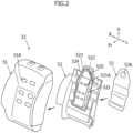
- Figure 2 is an exploded perspective view of the seatback cushion 32.
- the seatback cushion 32 has a cushion main-body part 51 having an elastic property, a flow-path-forming member 52 forming a flow path that circulates air between the seating surface and the blower fan 34, and a covering material 53 that covers an opening part of the flow path by adhering to the flow-path-forming member 52.
- a recessed part (not shown) is provided on the rear surface side of the cushion main-body part 51, and the flow-path-forming member 52 that is a body separate from the cushion main-body part 51 is loaded on the recessed part from the seat rear side.
- the flow path formed by the flow-path-forming member 52 is opened to the seat rear side, and the covering material 53 is adhesively fixed to the flow-path-forming member 52 so as to cover the opening part of the flow path from the seat rear side.
- a front surface of the cushion main-body part 51 serves as a seating surface (supporting surface) that supports the back of the occupant.
- a plurality of front blower ports 51A are formed ( Figure 1 and Figure 2 ).
- Each of the front blower ports 51A communicates with the flow path of air provided on the rear surface side of the cushion main-body part 51, and the air around the seating surface is guided to the blower fan 34 through each of the front blower ports 51A and the flow path or the air from the blower fan 34 is blown to the seating surface through the flow path and each of the front blower ports 51A.
- At least a part of the flow path of air provided on the rear surface side of the cushion main-body part 51 is formed by the flow-path-forming member 52 and the covering material 53.
- Specific structures of the flow-path-forming member 52 and the covering material 53 are described in detail below with reference also to Figure 3 to Figure 7 .
- Figure 3 is a perspective view of the flow-path-forming member 52 seen from diagonally behind
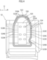
- Figure 4 is a rear view of the flow-path-forming member 52 of Figure 3
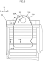
- Figure 5 is a rear view showing a state in which the covering material 53 is adhesively fixed to the flow-path-forming member 52 of Figure 4
- Figure 6 is a sectional view taken along line A-A of Figure 5
- Figure 7 is a sectional view taken along line B-B of Figure 5
- Figure 8 is a sectional view taken along line C-C of Figure 5 .
- the flow-path-forming member 52 is formed with use of a material harder than that of the cushion main-body part 51 and has an external form corresponding to the recessed part on the rear surface side of the cushion main-body part 51.
- the flow-path-forming member 52 is in a layer-like form that roughly spreads in the seat up-down direction and the seat width direction and has a plurality of protruding and recessed shapes formed therein in the seat front-rear direction.
- the flow-path-forming member 52 can be manufactured by a step different from that of the cushion main-body part 51; in other words, the protruding and recessed shapes can be formed in the flow-path-forming member 52 without depending on the manufacturing conditions of the cushion main-body part 51. Therefore, highly-accurate protruding and recessed shapes are easily realized. In addition, highly-accurate protruding and recessed shapes can be relatively easily realized by providing the flow-path-forming member 52 made of a material harder than that of the cushion main-body part 51 and forming the protruding and recessed shapes by the flow-path-forming member 52.
- a flow path 521 that extends in the seat up-down direction is formed near a central part in the seat width direction.
- the flow path 521 has a U-like shape in cross section that is recessed to the seat front side (the side of the cushion main-body part 51) and is opened to the seat rear side.
- rear blower ports 521A that pass therethrough in the seat front-rear direction are respectively formed in positions corresponding to each of the front blower ports 51A of the cushion main-body part 51.
- the flow-path-forming member 52 has an adhesion surface 522 that extends so as to surround the opening part of the flow path 521, and a first recessed part 523 and a second recessed part 524 that are disposed across the adhesion surface 522 and extend along the longitudinal direction of the adhesion surface 522.
- the adhesion surface 522 is provided on a surface of the flow-path-forming member 52 facing the seat rear side.
- the adhesion surface 522 is disposed to be spaced apart from the opening part of the flow path 521 to the outer side of the opening part of the flow path 521 and extends around the opening part of the flow path 521 so as to surround the opening part of the flow path 521.
- the covering material 53 adheres to the adhesion surface 522 from the seat rear side.
- An adhesion layer 54 formed by an adhesive agent is formed between the adhesion surface 522 and the covering material 53 ( Figure 6 to Figure 8 ).
- a fan opening part 525 is provided between an upper-end part of the flow path 521 and an upper part of the adhesion surface 522 in the flow-path-forming member 52.
- the fan opening part 525 is formed in a substantially semicircular shape when seen from an intersecting direction that intersects with the adhesion surface 522 (in rear view), and the blower fan 34 is inserted through the inside thereof.
- the first recessed part 523 is positioned between the flow path 521 and the adhesion surface 522 and is disposed to be adjacent to the adhesion surface 522.
- the first recessed part 523 extends along an edge of the adhesion surface 522 on the flow path 521 side thereof and extends around the opening part of the flow path 521 and the fan opening part 525 so as to surround the opening part of the flow path 521 and the fan opening part 525.
- the first recessed part 523 has a groove-like shape that is recessed to the seat front side (the side of the cushion main-body part 51) and is opened to the seat rear side.
- an outer side wall of the first recessed part 523 positioned on the adhesion surface 522 side thereof is disposed to be adjacent to an inner side edge of the adhesion surface 522 positioned on the flow path 521 side thereof.
- An inner side wall of the first recessed part 523 positioned on the side opposite from the adhesion surface 522 is disposed to be spaced apart from the opening part of the flow path 521 and the fan opening part 525 to the outer side of each of the opening part of the flow path 521 and the fan opening part 525.
- the inner side wall of the first recessed part 523 is disposed so as to maintain a fixed interval from the outer side wall of the first recessed part 523.
- the second recessed part 524 is positioned on the side opposite from the first recessed part 523 across the adhesion surface 522 and is disposed to be adjacent to the adhesion surface 522.
- the second recessed part 524 extends along an outer side edge of the adhesion surface 522 on the side opposite from the flow path 521 and extends around the opening part of the flow path 521 and the fan opening part 525 so as to surround the opening part of the flow path 521 and the fan opening part 525.
- the second recessed part 524 has a shape similar to that of the first recessed part 523; in other words, a groove-like shape that is recessed to the seat front side (the side of the cushion main-body part 51) and is opened to the seat rear side.
- an inner side wall of the second recessed part 524 positioned on the adhesion surface 522 side thereof is disposed to be adjacent to an outer side edge of the adhesion surface 522.
- An outer side wall of the second recessed part 524 positioned on the side opposite from the adhesion surface 522 is disposed so as to maintain a fixed interval from the inner side wall of the second recessed part 524.
- the interval between the first recessed part 523 and the second recessed part 524 in other words, the horizontal width of the adhesion surface 522 is formed to be substantially fixed.
- the adhesion surface 522 has a substantially fixed horizontal width as above, it becomes easier to apply the adhesive agent to the adhesion surface 522, and it also becomes easier to maintain the application amount of the adhesive agent to be fixed. Therefore, the adhesive fixation between the adhesion surface 522 and the covering material 53 becomes stable.
- the covering material 53 is adhesively fixed to the adhesion surface 522 of the flow-path-forming member 52 and covers the opening part of the flow path 521 from the seat rear side.
- the covering material 53 is formed with use of a cloth-like material with little air permeability (for example, felt and the like).
- a coupling part 53A to be coupled to the blower fan 34 is provided on an upper part of the covering material 53.
- the coupling part 53A has a substantially-circular external form in rear view and passes through the covering material 53 in the seat front-rear direction.
- a rear part of the blower fan 34 inserted through the fan opening part 525 of the flow-path-forming member 52 is coupled to the coupling part 53A.
- the outer side wall of the first recessed part 523 of the flow-path-forming member 52 has a first curved part 523A curved so as to surround the coupling part 53A of the covering material 53 ( Figure 3 and Figure 4 ).
- the inner side wall of the second recessed part 524 has a second curved part 524A curved so as to surround the coupling part 53A of the covering material 53 in a position corresponding to the first curved part 523A. Therefore, a part of the adhesion surface 522 of the flow-path-forming member 52 adjacent to the first curved part 523A and the second curved part 524A has a shape curved so as to surround the coupling part 53A of the covering material 53.
- a raised part 526 is formed in the flow-path-forming member 52 so as to correspond to the second curved part 524A ( Figure 3 to Figure 5 , and Figure 8 ).
- the raised part 526 is positioned on the side opposite from the adhesion surface 522 across the second recessed part 524 and is raised to the seat rear side along the second curved part 524A.
- a distal end surface (rear surface) of the raised part 526 is positioned on the seat rear side than the adhesion surface 522 positioned between the first curved part 523A and the second curved part 524A, and a difference in level is formed between the adhesion surface 522 and the distal end surface of the raised part 526 ( Figure 8 ).
- the difference in level can be used in positioning when the covering material 53 is affixed to the adhesion surface 522 of the flow-path-forming member 52.
- the raised part 526 may be formed so as to correspond to a part of the inner side wall of the second recessed part 524 other than the second curved part 524A.
- the outer side wall of the first recessed part 523 of the flow-path-forming member 52 has left and right first straight parts 523B, 523C that extend in a straight manner when seen from the intersecting direction that intersects with the adhesion surface 522 (in rear view).
- the first straight part 523B on the left side extends in the seat up-down direction on the left side of the flow path 521
- the first straight part 523C on the right side extends in the seat up-down direction on the right side of the flow path 521.
- Parts out of the inner side wall of the first recessed part 523 that face the first straight parts 523B, 523C also extend in the seat up-down direction in a straight manner.
- the inner side wall of the second recessed part 524 of the flow-path-forming member 52 is in a position corresponding to each of the left and right first straight parts 523B, 523C and has left and right second straight parts 524B, 524C that extend in a straight manner when seen from the intersecting direction that intersects with the adhesion surface 522 (in rear view).
- the second straight parts 524B, 524C extend in the seat up-down direction. Parts out of the outer side wall of the second recessed part 524 that face the second straight parts 524B, 524C also extend in the seat up-down direction in a straight manner.
- each of the lengths of the first straight part 523C and the second straight part 524C on the right side is formed to be shorter than each of the lengths of the first straight part 523B and the second straight part 524C on the left side.
- the first straight parts 523B, 523C and the second straight parts 524B, 524C are formed to be bilaterally asymmetrical.
- the outer side wall of the first recessed part 523 has a first bulging part 523D that bulges out to the flow path 521 side (left side) on the lower side of the first straight part 523C on the right side.
- the inner side wall of the second recessed part 524 has a second bulging part 524D that bulges out to the flow path 521 side (left side) on the lower side of the second straight part 524C on the right side.
- the adhesion surface 522 of the flow-path-forming member 52 has a surface-direction changing part 522B on the left side in a part positioned between the first straight part 523B and the second straight part 524B on the left side and has a surface-direction changing part 522C on the right side in a part positioned between the first straight part 523C and the second straight part 524C on the right side.
- the left and right surface-direction changing parts 522B, 522C are configured such that the direction along the adhesion surface 522 changes to the intersecting direction that intersects with the adhesion surface 522.
- the intersecting direction that intersects with the adhesion surface 522 corresponds to the adhesion direction of the covering material 53 in a step of causing the covering material 53 to adhere to the adhesion surface 522.
- a direction orthogonal to the adhesion surface 522 and the like correspond to the intersecting direction.
- a specific structure of the surface-direction changing part 522B on the left side is described in detail below with reference to Figure 6 (a sectional view taken along line A-A of Figure 5 ). Note that line A-A in Figure 5 is a straight line that extends along the longitudinal direction through the center of the surface-direction changing part 522B on the left side in the left-right direction.
- the surface-direction changing part 522C on the right side is similar to the surface-direction changing part 522B on the left side, and hence description here is omitted.
- an inclined part C1 As shown in Figure 6 , in the surface-direction changing part 522B on the left side in the adhesion surface 522 of the flow-path-forming member 52, an inclined part C1, a front protruding part C3 (first surface-direction changing part), a rear protruding part C5 (second surface-direction changing part), and a level-difference part C7 are consecutively formed in the seat up-down direction.
- dash-dot-dash lines in Figure 6 indicate a virtual reference surface R of the adhesion surface 522.
- the inclined part C1 is inclined to the seat front side with respect to the reference surface R.
- An upper end of the front protruding part C3 is connected to a lower end of the inclined part C1.
- the front protruding part C3 protrudes to the seat front side and includes a rear-side inclined part C2 on the upper-end side and an upper part of a front-side inclined part C4 on the lower-end side.
- the rear-side inclined part C2 is inclined to the seat rear side with respect to the reference surface R.
- the front-side inclined part C4 is inclined to the seat front side with respect to the reference surface R.
- An upper end of the rear protruding part C5 is connected to a lower end of the front protruding part C3.
- the rear protruding part C5 protrudes to the seat rear side and includes a lower part of the front-side inclined part C4 on the upper-end side and an upper part of a rear-side inclined part C6 on the lower-end side.
- the rear-side inclined part C6 is inclined to the seat rear side with respect to the reference surface R.
- An upper-end of the level-difference part C7 is connected to a lower end of the rear protruding part C5.
- the level-difference part C7 is positioned on the seat front side with respect to a bottom surface of the rear protruding part C5 and includes a lower part of the rear-side inclined part C6 on the upper-end side and a rear-side inclined part C8 on the lower-end side.
- a difference in level is formed between the bottom surface of the rear protruding part C5 and a surface positioned in the middle of the level-difference part C7 in the seat up-down direction.
- the rear-side inclined part C8 is inclined to the seat rear side with respect to the reference surface R.
- the covering material 53 is adhesively fixed to the surface-direction changing part 522B on the left side (and the surface-direction changing part 522C on the right side) as described above via the adhesion layer 54 formed by the adhesive agent described above. Therefore, recessions and protrusions similar to the surface-direction changing parts 522B, 522C are also formed in parts corresponding to the surface-direction changing parts 522B, 522C of the covering material 53.
- the surface-direction changing parts 522B, 522C are formed in parts in the adhesion surface 522 positioned between the first straight parts 523B, 523C and the second straight parts 524B, 524C have been described, but the surface-direction changing parts may be formed in other parts of the adhesion surface 522 besides those described above.
- a center P1 of the cross section in the width direction is positioned between both end parts of the adhesion surface in the width direction.
- the center P1 of the cross section of the adhesion layer 54 in the width direction in the present embodiment is positioned in a center P2 of the adhesion surface 522 in the width direction between the first recessed part 523 and the second recessed part 524.
- the adhesive agent is applied so as to include the part of the center P2 of the adhesion surface 522 in the width direction when the covering material 53 is caused to adhere to the adhesion surface 522 of the flow-path-forming member 52.
- line B-B of Figure 5 corresponds to a straight line that cuts across the surface-direction changing part 522B on the left side in the adhesion surface 522 in the left-right direction (seat-width rear side).
- a communicating space G that communicates with the space in the flow path 521 and the space in the first recessed part 523 is formed ( Figure 7 ).
- the communicating space G is formed in a section equivalent to the adhesion surface, and hence, the section can be deformed in the arrangement direction of the first and second recessed parts 523, 524 (the width direction of the adhesion surface 522).
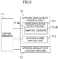
- FIG. 9 is a block diagram showing a configuration example of a manufacturing apparatus used in the adhesion step of the covering material 53.
- Figure 10 is a conceptual diagram describing the adhesion step of the covering material 53.
- the manufacturing apparatus used in the adhesion step of the covering material 53 includes an applying apparatus 71 of the adhesive agent, an affixing apparatus 72 of the covering material 53, and a control apparatus 73 that controls the operation of the applying apparatus 71 and the affixing apparatus 72.
- the applying apparatus 71 of the adhesive agent has an adhesion-surface detection unit 711 that detects the position of the adhesion surface 522 of the flow-path-forming member 52, and an adhesive-agent applying unit 712 that applies the adhesive agent to the adhesion surface 522 detected by the adhesion-surface detection unit 711.
- each processing of the manufacturing step as described below is performed by executing a preset program.
- the adhesion-surface detection unit 711 includes a transmitter 711A that transmits detection waves for detecting the adhesion surface 522 toward the flow-path-forming member 52, and a receiver 711B that receives the detection waves reflected by the flow-path-forming member 52.
- a transmitter 711A that transmits detection waves for detecting the adhesion surface 522 toward the flow-path-forming member 52
- a receiver 711B that receives the detection waves reflected by the flow-path-forming member 52.
- the detection waves output from the transmitter 711A for example, sound, light (a visible light ray or an invisible light ray), electromagnetic waves, and the like can be used.
- each of the positions of the first recessed part 523 and the second recessed part 524 of the flow-path-forming member 52 is detected on the basis of the waveform change of the detection waves received by the receiver 711B, and adhesion surface information including the position and the shape of the adhesion surface 522 is generated in accordance with the detection result thereof.
- the adhesion surface information is transmitted from the adhesion-surface detection unit 711 to the adhesive-agent applying unit 712 (the state shown in the upper stage of Figure 10 ).
- the adhesion surface 522 is formed between the first recessed part 523 and the second recessed part 524, and hence, the degree of reflection of the detection waves can be changed between the first recessed part 523 and the second recessed part 524, and the adhesion surface 522. Therefore, the position and the shape of the adhesion surface 522 can be easily detected with high accuracy on the basis of the waveform change of the detection waves received by the receiver 711B.
- the adhesive-agent applying unit 712 applies the adhesive agent to the adhesion surface 522 of the flow-path-forming member 52 on the basis of the adhesion surface information from the adhesion-surface detection unit 711. At this time, the adhesive agent is applied so as to include the center P2 of the adhesion surface 522 in the width direction (the state shown in the middle stage in Figure 10 ). The application amount of the adhesive agent to the adhesion surface 522 and the like are controlled in accordance with an output signal from the control apparatus 73. Note that the applying range of the adhesive agent may include the second recessed part 524 beyond the adhesion surface 522. However, the adhesive agent is preferably not applied on the first recessed part 523.
- the affixing apparatus 72 affixes the covering material 53 at a predetermined position on the adhesion surface 522 of the flow-path-forming member 52 to which the adhesive agent is applied by the applying apparatus 71.
- the position to which the covering material 53 is affixed and the like are controlled in accordance with an output signal from the control apparatus 73.
- the covering material 53 affixed to a predetermined position in the flow-path-forming member 52 by the affixing apparatus 72 is pressed to the side of the adhesion surface 522. At this time, the excess adhesive agent flows into the first recessed part 523 and/or the second recessed part 524.
- the covering material 53 is adhesively fixed to the adhesion surface 522 of the flow-path-forming member 52 via the adhesion layer 54 when the adhesive agent solidifies. At this time, the center P1 of the cross section of the adhesion layer 54 in the width direction overlaps on the center P2 of the adhesion surface 522 in the width direction (the state shown in the lower stage in Figure 10 ).
- the first recessed part 523 positioned between the flow path 521 and the adhesion surface 522 and disposed to be adjacent to the adhesion surface 522 is provided, the adhesion surface 522 and the first recessed part 523 extend so as to surround the opening part of the flow path 521, and the center P1 in the cross section of the adhesion layer 54 in the width direction is positioned between both end parts of the adhesion surface 522 in the width direction.
- the second recessed part 524 that is positioned on the side opposite from the first recessed part 523 across the adhesion surface 522, is disposed to be adjacent to the adhesion surface 522, and extends so as to surround the opening part of the flow path 521, is provided.
- the abovementioned excess adhesive agent can be released to the first recessed part 523 and/or the second recessed part 524, and hence, the adhesive fixation of the covering material 53 to the adhesion surface 522 can be further stabilized.
- the covering material 53 can be affixed to a desired position in the flow-path-forming member 52 by using the first recessed part 523 and the second recessed part 524 as a guide, and hence, the operation of affixing the covering material 53 can be easily performed.
- the center P1 in the cross section of the adhesion layer 54 in the width direction is positioned in the center P2 of the adhesion surface 522 in the width direction.
- the covering material 53 has the coupling part 53A coupled to the blower fan 34, and the outer side wall of the first recessed part 523 positioned on the adhesion surface 522 side thereof has the first curved part 523A curved so as to surround the coupling part of the covering material 53.
- the pressure negative pressure or positive pressure
- the pressure that acts on the adhesion surface 522 of the flow-path-forming member 52 when the blower fan 34 is driven is accepted by the entirety of the part of the adhesion surface 522 adjacent to the first curved part 523A, and local concentration of the pressure onto the adhesion surface 522 can be suppressed.
- the adhesively fixed state between the adhesion surface 522 of the flow-path-forming member 52 and the covering material 53 is easily maintained even when the blower fan 34 is used for a long period of time.
- the inner side wall of the second recessed part 524 positioned on the adhesion surface 522 side thereof has the second curved part 524A curved so as to surround the coupling part 53A of the covering material 53 in a position corresponding to the first curved part 523A of the first recessed part 523, and the flow-path-forming member 52 has the raised part 526 positioned on the side opposite from the adhesion surface 522 across the second recessed part 524 and raised along the second curved part 524A.
- the movement amount of the covering material 53 is restricted along the raised part 526 when the covering material 53 is affixed to the adhesion surface 522 of the flow-path-forming member 52. Therefore, the alignment of the covering material 53 can be easily and accurately performed. Therefore, the adhesion of the covering material 53 to the adhesion surface 522 can be stabilized even more.
- the pressure (negative pressure or positive pressure) generated near the coupling part 53A of the covering material 53 at the time of driving of the blower fan 34 is accepted by the entirety of the part of the adhesion surface 522 that is adjacent to both of the first curved part 523A and the second curved part 524A, and hence, local concentration of the pressure onto the adhesion surface 522 can also be effectively suppressed.
- the adhesively fixed state between the adhesion surface 522 of the flow-path-forming member 52 and the covering material 53 is further easily maintained even when the blower fan 34 is used for a long period of time.
- the adhesion surface 522 of the flow-path-forming member 52 has the surface-direction changing parts 522B, 522C between the first straight parts 523B, 523C of the outer side wall of the first recessed part 523 and the second straight parts 524B, 524C of the inner side wall of the second recessed part 524.
- the surface-direction changing parts 522B, 522C are configured such that the direction along the adhesion surface 522 changes to the intersecting direction that intersects with the adhesion surface 522.
- the adhesive fixation of the covering material 53 to the adhesion surface 522 can be stabilized more.
- the covering material 53 receives a load in the longitudinal direction (seat up-down direction) of the surface-direction changing parts 522B, 522C
- the load can be accepted by the surface-direction changing parts 522B, 522C. Therefore, deformation of the covering material 53 after the adhesion can be suppressed, and breakage and the like of the adhesion layer 54 can be suppressed.
- the surface-direction changing parts 522B, 522C have the front protruding part C3 and the rear protruding part C5 protruding or recessed in the intersecting direction.
- the stability of the adhesive fixation can be increased even more, and the deformation of the covering material 53 after the adhesion can be reliably suppressed.
- the covering material 53 is caused to adhere to the adhesion surface 522 such that the external form of the covering material 53 is positioned between the inner side wall and the outer side wall of the second recessed part 524.
- the second recessed part 524 is not covered with the covering material 53 even after the covering material 53 is affixed to the adhesion surface 522. Therefore, when the covering material 53 is affixed to the adhesion surface 522, the covering material 53 can be caused to approach the adhesion surface 522 by using the second recessed part 524 as a guide. Therefore, the covering material 53 can be reliably affixed to a desired position in the flow-path-forming member 52, and the operation of affixing the covering material 53 can be easily performed.
- the present invention is not limited to the embodiment described above, and various modifications and changes can be made on the basis of the technical idea of the present invention.
- the flow-path-forming member 52 a case in which the first recessed part 523 and the second recessed part 524 are provided across the adhesion surface 522 has been described.
- a structure in which only the first recessed part 523 is provided is also possible.
- the raised part 526 is formed on the side opposite from the first recessed part 523 across the adhesion surface 522.
- a structure in which the adhesion surface 522 is raised to the seat rear side with respect to a surface 527 in the flow-path-forming member 52 connected to an upper end of a side wall of the flow path 521 is also possible.
- the surface 527 of the flow-path-forming member 52 is equivalent to the bottom surface of the first recessed part 523 in the abovementioned embodiment.
- the flow-path-forming member 52 is provided as a body separate from the cushion main-body part 51
- a cushion member itself can serve as the flow-path-forming member when protruding, and recessed shapes of the flow path and the like can be formed in the cushion member with high accuracy.
- a case in which a material harder than that of the cushion main-body part 51 is used for the material of the flow-path-forming member 52 has been described, but the same material as the cushion main-body part 51 may be used.
- the flow-path-forming member 52 can be formed such that the flow-path-forming member 52 has a property with lower elasticity or higher rigidity than a front surface of the cushion main-body part 51.
- the blower fan 34 is disposed on the upper part of the seatback 30
- the seat structure of the present invention is effective when the blower fan 34 is disposed in a freely-selected position in the seatback 30 or the seating part 10.
- the covering material 53 is affixed to the adhesion surface 522 of the flow-path-forming member 52 with use of the affixing apparatus 72 has been described, but the operation of affixing the covering material 53 may be manually performed.
Landscapes
- Engineering & Computer Science (AREA)
- Aviation & Aerospace Engineering (AREA)
- Transportation (AREA)
- Mechanical Engineering (AREA)
- Seats For Vehicles (AREA)
- Chair Legs, Seat Parts, And Backrests (AREA)
- Air-Conditioning For Vehicles (AREA)
Abstract
Description
- The present invention relates to a vehicle seat structure and to a manufacturing method therefor.
- Conventionally, as seats used in vehicles such as automobiles, a seat with an air conditioning function that is capable of conditioning air around a seating surface of a seating part and a seating surface of a seatback is known. In the vehicle seat with the air conditioning function, a highly-breathable surface material is used in the seating surface, and a flow path (circulation space) for circulating air between the seating surface and a blower apparatus (fan) is formed on the inside of a cushion member covered with the surface material. When the flow path has a complicated shape, the following may be performed. Specifically, when the cushion member is manufactured by causing a foaming material to foam, a part of a wall surface for forming the flow path is formed by the cushion member, and the remaining wall surface is prepared as a member different from the cushion member. When the vehicle seat is manufactured, the remaining wall surface is fixed to the cushion member. As a result, the flow path is formed in the cushion member.
- For example, in
Patent Literature 1, a flow path part opened to the rear side and a recessed part that surrounds the flow path part are formed in a back surface of the cushion member, and an adhesive agent is placed in a heaped state in the recessed part. Then, a lid member is adhesively fixed to the back surface of the cushion member while being overlapped on the back surface of the cushion member. As a result, the flow path part is covered. As a result, the adhesive agent is solidified in the recessed part in a bolt-like form, and the relative movement of the lid member with respect to the cushion member in the surface direction is restricted. - [Patent Literature 1]
JP 2013-100000 A - However, when the adhesive agent is injected to the recessed part formed in the cushion member as in
Patent Literature 1 described above, there is a concern that the sectional shape of the recessed part may change when a variation in the depth of the recessed part and the width of the recessed part occurs due to the conditions (for example, the state, the foaming conditions, and the manufacturing environment of the cushion material) at the time of manufacturing of the cushion member and the like. When there is a variation in the sectional shape of the recessed part, there is a concern that the amount of the adhesive agent heaped up in the recessed part may be partially excessive or partially insufficient. There has been a problem in that the excess adhesive agent may flow into the flow path and block the flow of air in parts where the adhesive agent is excessive, and the adhesion of the lid member with respect to the cushion member becomes unstable in parts where the adhesive agent is insufficient. - The present invention has been made in view of the abovementioned point, and an object thereof is to provide a vehicle seat structure and a manufacturing method thereof capable of adhesively fixing a covering material to a flow-path-forming member in a stable manner without blocking the flow of air in a flow path.
- One aspect of the present invention for achieving the abovementioned object provides a vehicle seat structure including: a blower apparatus that conditions air around a seating surface of a vehicle seat; a flow-path-forming member that forms a flow path that circulates air between the seating surface and the blower apparatus; and a covering material that adheres to the flow-path-forming member and covers an opening part of the flow path. In the vehicle seat structure, the flow-path-forming member has: an adhesion surface to which the covering material adheres via an adhesion layer formed by an adhesive agent; and a first recessed part positioned between the flow path and the adhesion surface and disposed to be adjacent to the adhesion surface. In the vehicle seat structure, the adhesion surface and the first recessed part extend so as to surround the opening part of the flow path, and a center in a cross section of the adhesion layer in a width direction is positioned between both end parts of the adhesion surface in a width direction.
- According to the vehicle seat structure according to the present invention, it becomes possible to release excess adhesive agent to the first recessed part even when sufficient amount of adhesive agent is applied onto the adhesion surface. Therefore, without blocking the flow of air in the flow path, it becomes possible to adhesively fix the covering material to the flow-path-forming member in a stable manner.
-
- [
Figure 1] Figure 1 is a perspective view showing the external appearance of a vehicle seat structure according to one embodiment of the present invention. - [
Figure 2] Figure 2 is an exploded perspective view of a seatback cushion in the embodiment. - [
Figure 3] Figure 3 is a perspective view of a flow-path-forming member in the embodiment seen from diagonally behind. - [
Figure 4] Figure 4 is a rear view of the flow-path-forming member ofFigure 3 . - [
Figure 5] Figure 5 is a rear view showing a state in which a covering material is adhesively fixed to the flow-path-forming member ofFigure 4 . - [
Figure 6] Figure 6 is a sectional view taken along line A-A ofFigure 5 . - [
Figure 7] Figure 7 is a sectional view taken along line B-B ofFigure 5 . - [
Figure 8] Figure 8 is a sectional view taken along line C-C ofFigure 5 . - [
Figure 9] Figure 9 is a block diagram showing a configuration example of a manufacturing apparatus used in an adhesion step of the covering material in the embodiment. - [
Figure 10] Figure 10 is a conceptual diagram describing the adhesion step of the covering material in the embodiment. - [
Figure 11] Figure 11 is a sectional view showing a modification relating to the embodiment. - [
Figure 12] Figure 12 is a sectional view showing another modification relating to the embodiment. - Description will be given below on a vehicle seat structure and a manufacturing method therefor according to one embodiment of the present invention with reference to the drawings.
-
Figure 1 is a perspective view showing the external appearance of avehicle seat 1 to which a structure according to the present embodiment is applied. Note that, in the drawings described below, arrow Fr indicates the front side in the front-rear direction of the vehicle seat. The "front part (front end) and rear part (rear end)" in the description of the embodiment correspond to the front part and the rear part in the seat front-rear direction.
The front side in the seat front-rear direction in the present embodiment corresponds to the front side in the vehicle front-rear direction. The direction of arrow R and the direction of arrow L indicate the right side and the left side when an occupant sits on the vehicle seat. The direction of arrow U indicates the upper side. - In
Figure 1 , thevehicle seat 1 includes aseating part 10 and aseatback 30. - The
seating part 10 is a part on which an occupant sits. Theseating part 10 has a seating-part frame 11, a seating-part cushion 12 forming a sitting surface, and a seating-part cover 13 that covers the seating-part cushion 12. - The seating-
part frame 11 configures the framework of theseating part 10. Both side portions of a lower part of the seating-part frame 11 in the seat width direction are mounted on left andright seat rails 2 via running parts (not shown) in a movable manner. Theseat rails 2 are provided on a floor part (not shown) in a vehicle interior and extend in the vehicle front-rear direction. - The seating-
part cushion 12 has an elastic property and is installed on an upper part of the seating-part frame 11. An upper part of the seating-part cushion 12 forms the sitting surface on which an occupant sits. - The seating-
part cover 13 is a trim that covers the seating-part cushion 12 from the upper side. The seating-part cover 13 covers the upper part (sitting surface), a front part, a rear part, and both left and right side parts of the seating-part cushion 12. - The
seatback 30 is a part that extends to the upper side from a rear part of theseating part 10 and is configured so as to support, in particular, the upper body of the occupant sitting on theseating part 10. Theseatback 30 has a seatback frame (not shown) configuring the framework of theseatback 30, aseatback cushion 32 forming the seating surface, aseatback cover 33 that covers theseatback cushion 32, ablower fan 34 that conditions the air around the seating surface, aheadrest 35 that supports the head of the occupant sitting on theseating part 10 of thevehicle seat 1, and an airbag apparatus (side airbag) 36 that protects the occupant at the time of a side collision. Note that, in the present embodiment, theblower fan 34 corresponds to a "blower apparatus" of the present invention. - The seatback frame is formed in a substantially rectangular shape by bending a pipe-like member. On an upper part of the seatback frame, a fan-fixing bracket (not shown) is mounted, and the
blower fan 34 is fixed via the fan-fixing bracket. In a right side part of the seatback frame, an airbag-fixing bracket (not shown) is mounted, and theairbag apparatus 36 is fixed via the airbag-fixing bracket. Theairbag apparatus 36 is disposed on the vehicle-width-direction outer side in the vehicle interior. Theseatback cushion 32 is installed in a front part of the seatback frame. -
Figure 2 is an exploded perspective view of theseatback cushion 32. - As shown in
Figure 2 , theseatback cushion 32 has a cushion main-body part 51 having an elastic property, a flow-path-formingmember 52 forming a flow path that circulates air between the seating surface and theblower fan 34, and a coveringmaterial 53 that covers an opening part of the flow path by adhering to the flow-path-formingmember 52. In theseatback cushion 32 according to the present embodiment, a recessed part (not shown) is provided on the rear surface side of the cushion main-body part 51, and the flow-path-formingmember 52 that is a body separate from the cushion main-body part 51 is loaded on the recessed part from the seat rear side. The flow path formed by the flow-path-formingmember 52 is opened to the seat rear side, and the coveringmaterial 53 is adhesively fixed to the flow-path-formingmember 52 so as to cover the opening part of the flow path from the seat rear side. - Specifically, a front surface of the cushion main-
body part 51 serves as a seating surface (supporting surface) that supports the back of the occupant. On the front surface side of the cushion main-body part 51, a plurality offront blower ports 51A are formed (Figure 1 andFigure 2 ). Each of thefront blower ports 51A communicates with the flow path of air provided on the rear surface side of the cushion main-body part 51, and the air around the seating surface is guided to theblower fan 34 through each of thefront blower ports 51A and the flow path or the air from theblower fan 34 is blown to the seating surface through the flow path and each of thefront blower ports 51A. In the present embodiment, at least a part of the flow path of air provided on the rear surface side of the cushion main-body part 51 is formed by the flow-path-formingmember 52 and the coveringmaterial 53. Specific structures of the flow-path-formingmember 52 and the coveringmaterial 53 are described in detail below with reference also toFigure 3 to Figure 7 . -
Figure 3 is a perspective view of the flow-path-formingmember 52 seen from diagonally behind, andFigure 4 is a rear view of the flow-path-formingmember 52 ofFigure 3 .Figure 5 is a rear view showing a state in which the coveringmaterial 53 is adhesively fixed to the flow-path-formingmember 52 ofFigure 4 .Figure 6 is a sectional view taken along line A-A ofFigure 5 ,Figure 7 is a sectional view taken along line B-B ofFigure 5 , andFigure 8 is a sectional view taken along line C-C ofFigure 5 . - As shown in
Figure 2 to Figure 4 , the flow-path-formingmember 52 is formed with use of a material harder than that of the cushion main-body part 51 and has an external form corresponding to the recessed part on the rear surface side of the cushion main-body part 51. The flow-path-formingmember 52 is in a layer-like form that roughly spreads in the seat up-down direction and the seat width direction and has a plurality of protruding and recessed shapes formed therein in the seat front-rear direction. By combining the flow-path-formingmember 52 as above with the cushion main-body part 51, protruding and recessed shapes of the flow path and the like provided on the inside of theseatback cushion 32 can be realized with high accuracy. - In other words, when the protruding and recessed shapes of the flow path and the like are to be directly formed at the time of molding of the cushion main-
body part 51 using a foamed material and the like, it may be difficult to accurately realize the protruding and recessed shapes due to the manufacturing conditions in a foaming step and the like of the cushion main-body part 51 and the manufacturing conditions for forming the protruding and recessed shapes with high accuracy being different from each other. Thus, by causing the flow-path-formingmember 52 to be a body separate from the cushion main-body part 51, the flow-path-formingmember 52 can be manufactured by a step different from that of the cushion main-body part 51; in other words, the protruding and recessed shapes can be formed in the flow-path-formingmember 52 without depending on the manufacturing conditions of the cushion main-body part 51. Therefore, highly-accurate protruding and recessed shapes are easily realized. In addition, highly-accurate protruding and recessed shapes can be relatively easily realized by providing the flow-path-formingmember 52 made of a material harder than that of the cushion main-body part 51 and forming the protruding and recessed shapes by the flow-path-formingmember 52. - In the flow-path-forming
member 52 in the present embodiment, aflow path 521 that extends in the seat up-down direction is formed near a central part in the seat width direction. Theflow path 521 has a U-like shape in cross section that is recessed to the seat front side (the side of the cushion main-body part 51) and is opened to the seat rear side. In a front wall (bottom part) of theflow path 521,rear blower ports 521A that pass therethrough in the seat front-rear direction are respectively formed in positions corresponding to each of thefront blower ports 51A of the cushion main-body part 51. - The flow-path-forming
member 52 has anadhesion surface 522 that extends so as to surround the opening part of theflow path 521, and a first recessedpart 523 and a second recessedpart 524 that are disposed across theadhesion surface 522 and extend along the longitudinal direction of theadhesion surface 522. - The
adhesion surface 522 is provided on a surface of the flow-path-formingmember 52 facing the seat rear side. Theadhesion surface 522 is disposed to be spaced apart from the opening part of theflow path 521 to the outer side of the opening part of theflow path 521 and extends around the opening part of theflow path 521 so as to surround the opening part of theflow path 521. The coveringmaterial 53 adheres to theadhesion surface 522 from the seat rear side. Anadhesion layer 54 formed by an adhesive agent is formed between theadhesion surface 522 and the covering material 53 (Figure 6 to Figure 8 ). Afan opening part 525 is provided between an upper-end part of theflow path 521 and an upper part of theadhesion surface 522 in the flow-path-formingmember 52. Thefan opening part 525 is formed in a substantially semicircular shape when seen from an intersecting direction that intersects with the adhesion surface 522 (in rear view), and theblower fan 34 is inserted through the inside thereof. - The first recessed
part 523 is positioned between theflow path 521 and theadhesion surface 522 and is disposed to be adjacent to theadhesion surface 522. In the present embodiment, the first recessedpart 523 extends along an edge of theadhesion surface 522 on theflow path 521 side thereof and extends around the opening part of theflow path 521 and thefan opening part 525 so as to surround the opening part of theflow path 521 and thefan opening part 525. The first recessedpart 523 has a groove-like shape that is recessed to the seat front side (the side of the cushion main-body part 51) and is opened to the seat rear side. In other words, an outer side wall of the first recessedpart 523 positioned on theadhesion surface 522 side thereof is disposed to be adjacent to an inner side edge of theadhesion surface 522 positioned on theflow path 521 side thereof. An inner side wall of the first recessedpart 523 positioned on the side opposite from theadhesion surface 522 is disposed to be spaced apart from the opening part of theflow path 521 and thefan opening part 525 to the outer side of each of the opening part of theflow path 521 and thefan opening part 525.
The inner side wall of the first recessedpart 523 is disposed so as to maintain a fixed interval from the outer side wall of the first recessedpart 523. - The second recessed
part 524 is positioned on the side opposite from the first recessedpart 523 across theadhesion surface 522 and is disposed to be adjacent to theadhesion surface 522. In the present embodiment, the second recessedpart 524 extends along an outer side edge of theadhesion surface 522 on the side opposite from theflow path 521 and extends around the opening part of theflow path 521 and thefan opening part 525 so as to surround the opening part of theflow path 521 and thefan opening part 525. The second recessedpart 524 has a shape similar to that of the first recessedpart 523; in other words, a groove-like shape that is recessed to the seat front side (the side of the cushion main-body part 51) and is opened to the seat rear side. In other words, an inner side wall of the second recessedpart 524 positioned on theadhesion surface 522 side thereof is disposed to be adjacent to an outer side edge of theadhesion surface 522. An outer side wall of the second recessedpart 524 positioned on the side opposite from theadhesion surface 522 is disposed so as to maintain a fixed interval from the inner side wall of the second recessedpart 524. - In the present embodiment, the interval between the first recessed
part 523 and the second recessedpart 524, in other words, the horizontal width of theadhesion surface 522 is formed to be substantially fixed. When theadhesion surface 522 has a substantially fixed horizontal width as above, it becomes easier to apply the adhesive agent to theadhesion surface 522, and it also becomes easier to maintain the application amount of the adhesive agent to be fixed. Therefore, the adhesive fixation between theadhesion surface 522 and the coveringmaterial 53 becomes stable. - As shown in
Figure 2 andFigure 5 , the coveringmaterial 53 is adhesively fixed to theadhesion surface 522 of the flow-path-formingmember 52 and covers the opening part of theflow path 521 from the seat rear side. The coveringmaterial 53 is formed with use of a cloth-like material with little air permeability (for example, felt and the like). Acoupling part 53A to be coupled to theblower fan 34 is provided on an upper part of the coveringmaterial 53. Thecoupling part 53A has a substantially-circular external form in rear view and passes through the coveringmaterial 53 in the seat front-rear direction. A rear part of theblower fan 34 inserted through thefan opening part 525 of the flow-path-formingmember 52 is coupled to thecoupling part 53A. - In a state in which the covering
material 53 is caused to adhere to theadhesion surface 522 of the flow-path-formingmember 52, the outer side wall of the first recessedpart 523 of the flow-path-formingmember 52 has a firstcurved part 523A curved so as to surround thecoupling part 53A of the covering material 53 (Figure 3 andFigure 4 ). The inner side wall of the second recessedpart 524 has a secondcurved part 524A curved so as to surround thecoupling part 53A of the coveringmaterial 53 in a position corresponding to the firstcurved part 523A. Therefore, a part of theadhesion surface 522 of the flow-path-formingmember 52 adjacent to the firstcurved part 523A and the secondcurved part 524A has a shape curved so as to surround thecoupling part 53A of the coveringmaterial 53. - A raised
part 526 is formed in the flow-path-formingmember 52 so as to correspond to the secondcurved part 524A (Figure 3 to Figure 5 , andFigure 8 ). The raisedpart 526 is positioned on the side opposite from theadhesion surface 522 across the second recessedpart 524 and is raised to the seat rear side along the secondcurved part 524A. In other words, a distal end surface (rear surface) of the raisedpart 526 is positioned on the seat rear side than theadhesion surface 522 positioned between the firstcurved part 523A and the secondcurved part 524A, and a difference in level is formed between theadhesion surface 522 and the distal end surface of the raised part 526 (Figure 8 ). The difference in level can be used in positioning when the coveringmaterial 53 is affixed to theadhesion surface 522 of the flow-path-formingmember 52. Note that the raisedpart 526 may be formed so as to correspond to a part of the inner side wall of the second recessedpart 524 other than the secondcurved part 524A. - The outer side wall of the first recessed
part 523 of the flow-path-formingmember 52 has left and right firststraight parts straight part 523B on the left side extends in the seat up-down direction on the left side of theflow path 521, and the firststraight part 523C on the right side extends in the seat up-down direction on the right side of theflow path 521. Parts out of the inner side wall of the first recessedpart 523 that face the firststraight parts - The inner side wall of the second recessed
part 524 of the flow-path-formingmember 52 is in a position corresponding to each of the left and right firststraight parts straight parts straight parts straight parts part 524 that face the secondstraight parts - Each of the lengths of the first
straight part 523C and the secondstraight part 524C on the right side is formed to be shorter than each of the lengths of the firststraight part 523B and the secondstraight part 524C on the left side. In other words, the firststraight parts straight parts part 523 has a first bulgingpart 523D that bulges out to theflow path 521 side (left side) on the lower side of the firststraight part 523C on the right side. The inner side wall of the second recessedpart 524 has a second bulgingpart 524D that bulges out to theflow path 521 side (left side) on the lower side of the secondstraight part 524C on the right side. By providing the first bulgingpart 523D and the second bulgingpart 524D as above, the area of theadhesion surface 522 of the flow-path-formingmember 52 is increased, and it becomes easier to distinguish the front and back of the coveringmaterial 53 from each other when the coveringmaterial 53 is affixed to theadhesion surface 522. - The
adhesion surface 522 of the flow-path-formingmember 52 has a surface-direction changing part 522B on the left side in a part positioned between the firststraight part 523B and the secondstraight part 524B on the left side and has a surface-direction changing part 522C on the right side in a part positioned between the firststraight part 523C and the secondstraight part 524C on the right side. The left and right surface-direction changing parts adhesion surface 522 changes to the intersecting direction that intersects with theadhesion surface 522. The intersecting direction that intersects with theadhesion surface 522 corresponds to the adhesion direction of the coveringmaterial 53 in a step of causing the coveringmaterial 53 to adhere to theadhesion surface 522. For example, a direction orthogonal to theadhesion surface 522 and the like correspond to the intersecting direction. A specific structure of the surface-direction changing part 522B on the left side is described in detail below with reference toFigure 6 (a sectional view taken along line A-A ofFigure 5 ). Note that line A-A inFigure 5 is a straight line that extends along the longitudinal direction through the center of the surface-direction changing part 522B on the left side in the left-right direction. The surface-direction changing part 522C on the right side is similar to the surface-direction changing part 522B on the left side, and hence description here is omitted. - As shown in
Figure 6 , in the surface-direction changing part 522B on the left side in theadhesion surface 522 of the flow-path-formingmember 52, an inclined part C1, a front protruding part C3 (first surface-direction changing part), a rear protruding part C5 (second surface-direction changing part), and a level-difference part C7 are consecutively formed in the seat up-down direction. Note that dash-dot-dash lines inFigure 6 indicate a virtual reference surface R of theadhesion surface 522. - The inclined part C1 is inclined to the seat front side with respect to the reference surface R. An upper end of the front protruding part C3 is connected to a lower end of the inclined part C1.
- The front protruding part C3 protrudes to the seat front side and includes a rear-side inclined part C2 on the upper-end side and an upper part of a front-side inclined part C4 on the lower-end side. The rear-side inclined part C2 is inclined to the seat rear side with respect to the reference surface R. The front-side inclined part C4 is inclined to the seat front side with respect to the reference surface R. An upper end of the rear protruding part C5 is connected to a lower end of the front protruding part C3.
- The rear protruding part C5 protrudes to the seat rear side and includes a lower part of the front-side inclined part C4 on the upper-end side and an upper part of a rear-side inclined part C6 on the lower-end side. As with the rear-side inclined part C2, the rear-side inclined part C6 is inclined to the seat rear side with respect to the reference surface R. An upper-end of the level-difference part C7 is connected to a lower end of the rear protruding part C5.
- The level-difference part C7 is positioned on the seat front side with respect to a bottom surface of the rear protruding part C5 and includes a lower part of the rear-side inclined part C6 on the upper-end side and a rear-side inclined part C8 on the lower-end side. In other words, a difference in level is formed between the bottom surface of the rear protruding part C5 and a surface positioned in the middle of the level-difference part C7 in the seat up-down direction. As with the rear-side inclined part C2, the rear-side inclined part C8 is inclined to the seat rear side with respect to the reference surface R.
- The covering
material 53 is adhesively fixed to the surface-direction changing part 522B on the left side (and the surface-direction changing part 522C on the right side) as described above via theadhesion layer 54 formed by the adhesive agent described above. Therefore, recessions and protrusions similar to the surface-direction changing parts direction changing parts material 53. Note that, in the present embodiment, one example in which the surface-direction changing parts adhesion surface 522 positioned between the firststraight parts straight parts adhesion surface 522 besides those described above. - As shown in
Figure 7 and Figure 8 , in theadhesion layer 54 formed between theadhesion surface 522 of the flow-path-formingmember 52 and the coveringmaterial 53, a center P1 of the cross section in the width direction is positioned between both end parts of the adhesion surface in the width direction. The center P1 of the cross section of theadhesion layer 54 in the width direction in the present embodiment is positioned in a center P2 of theadhesion surface 522 in the width direction between the first recessedpart 523 and the second recessedpart 524. In other words, the adhesive agent is applied so as to include the part of the center P2 of theadhesion surface 522 in the width direction when the coveringmaterial 53 is caused to adhere to theadhesion surface 522 of the flow-path-formingmember 52. Note that line B-B ofFigure 5 corresponds to a straight line that cuts across the surface-direction changing part 522B on the left side in theadhesion surface 522 in the left-right direction (seat-width rear side). By applying the adhesive agent to theadhesion surface 522 as above, even when the application amount of the adhesive agent is excessive, the excess adhesive agent flows into the first recessedpart 523 and/or the second recessed part 524 (the dotted line part inFigure 7 ). Therefore, a case in which the excess adhesive agent flows into theflow path 521 in a position spaced apart from the first recessedpart 523 and blocks the flow of air is avoided. - When the
adhesion layer 54 as described above is interposed between theadhesion surface 522 and the coveringmaterial 53, a communicating space G that communicates with the space in theflow path 521 and the space in the first recessedpart 523 is formed (Figure 7 ). By the communicating space G as above, the circulation space of the air can be expanded, and hence, the amount of air blown by theblower fan 34 can be increased. In addition, the communicating space G is formed in a section equivalent to the adhesion surface, and hence, the section can be deformed in the arrangement direction of the first and second recessedparts 523, 524 (the width direction of the adhesion surface 522). As a result, a case in which excessive pressure (negative pressure or positive pressure) acts on a place between theadhesion surface 522 and the coveringmaterial 53 and the adhesion state becomes unstable, can be suppressed. - One specific example of the step of causing the covering
material 53 to adhere to theadhesion surface 522 of the flow-path-formingmember 52 in the manufacturing of thevehicle seat 1 according to the present embodiment is described in detail with reference toFigure 9 andFigure 10 .Figure 9 is a block diagram showing a configuration example of a manufacturing apparatus used in the adhesion step of the coveringmaterial 53.Figure 10 is a conceptual diagram describing the adhesion step of the coveringmaterial 53. - As shown in
Figure 9 , for example, the manufacturing apparatus used in the adhesion step of the coveringmaterial 53 includes an applyingapparatus 71 of the adhesive agent, an affixingapparatus 72 of the coveringmaterial 53, and acontrol apparatus 73 that controls the operation of the applyingapparatus 71 and the affixingapparatus 72. - The applying
apparatus 71 of the adhesive agent has an adhesion-surface detection unit 711 that detects the position of theadhesion surface 522 of the flow-path-formingmember 52, and an adhesive-agent applying unit 712 that applies the adhesive agent to theadhesion surface 522 detected by the adhesion-surface detection unit 711. In the applyingapparatus 71, each processing of the manufacturing step as described below is performed by executing a preset program. - The adhesion-
surface detection unit 711 includes atransmitter 711A that transmits detection waves for detecting theadhesion surface 522 toward the flow-path-formingmember 52, and areceiver 711B that receives the detection waves reflected by the flow-path-formingmember 52. As the detection waves output from thetransmitter 711A, for example, sound, light (a visible light ray or an invisible light ray), electromagnetic waves, and the like can be used. In the adhesion-surface detection unit 711, each of the positions of the first recessedpart 523 and the second recessedpart 524 of the flow-path-formingmember 52 is detected on the basis of the waveform change of the detection waves received by thereceiver 711B, and adhesion surface information including the position and the shape of theadhesion surface 522 is generated in accordance with the detection result thereof. The adhesion surface information is transmitted from the adhesion-surface detection unit 711 to the adhesive-agent applying unit 712 (the state shown in the upper stage ofFigure 10 ). - In processing for detecting the
adhesion surface 522 by the adhesion-surface detection unit 711 described above, theadhesion surface 522 is formed between the first recessedpart 523 and the second recessedpart 524, and hence, the degree of reflection of the detection waves can be changed between the first recessedpart 523 and the second recessedpart 524, and theadhesion surface 522. Therefore, the position and the shape of theadhesion surface 522 can be easily detected with high accuracy on the basis of the waveform change of the detection waves received by thereceiver 711B. - The adhesive-
agent applying unit 712 applies the adhesive agent to theadhesion surface 522 of the flow-path-formingmember 52 on the basis of the adhesion surface information from the adhesion-surface detection unit 711. At this time, the adhesive agent is applied so as to include the center P2 of theadhesion surface 522 in the width direction (the state shown in the middle stage inFigure 10 ). The application amount of the adhesive agent to theadhesion surface 522 and the like are controlled in accordance with an output signal from thecontrol apparatus 73. Note that the applying range of the adhesive agent may include the second recessedpart 524 beyond theadhesion surface 522. However, the adhesive agent is preferably not applied on the first recessedpart 523. - The affixing
apparatus 72 affixes the coveringmaterial 53 at a predetermined position on theadhesion surface 522 of the flow-path-formingmember 52 to which the adhesive agent is applied by the applyingapparatus 71. The position to which the coveringmaterial 53 is affixed and the like are controlled in accordance with an output signal from thecontrol apparatus 73. The coveringmaterial 53 affixed to a predetermined position in the flow-path-formingmember 52 by the affixingapparatus 72 is pressed to the side of theadhesion surface 522. At this time, the excess adhesive agent flows into the first recessedpart 523 and/or the second recessedpart 524. The coveringmaterial 53 is adhesively fixed to theadhesion surface 522 of the flow-path-formingmember 52 via theadhesion layer 54 when the adhesive agent solidifies. At this time, the center P1 of the cross section of theadhesion layer 54 in the width direction overlaps on the center P2 of theadhesion surface 522 in the width direction (the state shown in the lower stage inFigure 10 ). - As described above, in the
vehicle seat 1 according to the present embodiment, regarding the flow-path-formingmember 52, the first recessedpart 523 positioned between theflow path 521 and theadhesion surface 522 and disposed to be adjacent to theadhesion surface 522 is provided, theadhesion surface 522 and the first recessedpart 523 extend so as to surround the opening part of theflow path 521, and the center P1 in the cross section of theadhesion layer 54 in the width direction is positioned between both end parts of theadhesion surface 522 in the width direction. By the structure as above, the following occurs when the coveringmaterial 53 is affixed to theadhesion surface 522. Even when the application amount of the adhesive agent on theadhesion surface 522 becomes excessive the excess adhesive agent can be released to the first recessedpart 523. As a result, a case in which the adhesive agent flows into theflow path 521 and blocks the flow of air can be prevented, and adhesive fixation of the coveringmaterial 53 to theadhesion surface 522 by a sufficient application amount of the adhesive agent can be stabilized. - In the flow-path-forming
member 52 of thevehicle seat 1 according to the present embodiment, the second recessedpart 524 that is positioned on the side opposite from the first recessedpart 523 across theadhesion surface 522, is disposed to be adjacent to theadhesion surface 522, and extends so as to surround the opening part of theflow path 521, is provided. In the structure as above, the abovementioned excess adhesive agent can be released to the first recessedpart 523 and/or the second recessedpart 524, and hence, the adhesive fixation of the coveringmaterial 53 to theadhesion surface 522 can be further stabilized. In addition, the coveringmaterial 53 can be affixed to a desired position in the flow-path-formingmember 52 by using the first recessedpart 523 and the second recessedpart 524 as a guide, and hence, the operation of affixing the coveringmaterial 53 can be easily performed. - In the
vehicle seat 1 according to the present embodiment, the center P1 in the cross section of theadhesion layer 54 in the width direction is positioned in the center P2 of theadhesion surface 522 in the width direction. As a result, the abovementioned excess adhesive agent can be easily released to the first recessedpart 523 and/or the second recessedpart 524, and hence, the adhesion of the coveringmaterial 53 to theadhesion surface 522 can be further stabilized. - In the
vehicle seat 1 according to the present embodiment, the coveringmaterial 53 has thecoupling part 53A coupled to theblower fan 34, and the outer side wall of the first recessedpart 523 positioned on theadhesion surface 522 side thereof has the firstcurved part 523A curved so as to surround the coupling part of the coveringmaterial 53. In the structure as above, the pressure (negative pressure or positive pressure) that acts on theadhesion surface 522 of the flow-path-formingmember 52 when theblower fan 34 is driven is accepted by the entirety of the part of theadhesion surface 522 adjacent to the firstcurved part 523A, and local concentration of the pressure onto theadhesion surface 522 can be suppressed. As a result, the adhesively fixed state between theadhesion surface 522 of the flow-path-formingmember 52 and the coveringmaterial 53 is easily maintained even when theblower fan 34 is used for a long period of time. - In the
vehicle seat 1 according to the present embodiment, the inner side wall of the second recessedpart 524 positioned on theadhesion surface 522 side thereof has the secondcurved part 524A curved so as to surround thecoupling part 53A of the coveringmaterial 53 in a position corresponding to the firstcurved part 523A of the first recessedpart 523, and the flow-path-formingmember 52 has the raisedpart 526 positioned on the side opposite from theadhesion surface 522 across the second recessedpart 524 and raised along the secondcurved part 524A. By providing the raisedpart 526 raised along the longitudinal direction of theadhesion surface 522 as above, the movement amount of the coveringmaterial 53 is restricted along the raisedpart 526 when the coveringmaterial 53 is affixed to theadhesion surface 522 of the flow-path-formingmember 52. Therefore, the alignment of the coveringmaterial 53 can be easily and accurately performed. Therefore, the adhesion of the coveringmaterial 53 to theadhesion surface 522 can be stabilized even more. In addition, the pressure (negative pressure or positive pressure) generated near thecoupling part 53A of the coveringmaterial 53 at the time of driving of theblower fan 34 is accepted by the entirety of the part of theadhesion surface 522 that is adjacent to both of the firstcurved part 523A and the secondcurved part 524A, and hence, local concentration of the pressure onto theadhesion surface 522 can also be effectively suppressed. As a result, the adhesively fixed state between theadhesion surface 522 of the flow-path-formingmember 52 and the coveringmaterial 53 is further easily maintained even when theblower fan 34 is used for a long period of time. - In the
vehicle seat 1 according to the present embodiment, theadhesion surface 522 of the flow-path-formingmember 52 has the surface-direction changing parts straight parts part 523 and the secondstraight parts part 524. The surface-direction changing parts adhesion surface 522 changes to the intersecting direction that intersects with theadhesion surface 522. By forming the surface-direction changing parts adhesion surface 522, the adhesion area can be increased. Therefore, the adhesive fixation of the coveringmaterial 53 to theadhesion surface 522 can be stabilized more. When the coveringmaterial 53 receives a load in the longitudinal direction (seat up-down direction) of the surface-direction changing parts direction changing parts material 53 after the adhesion can be suppressed, and breakage and the like of theadhesion layer 54 can be suppressed. In particular, the surface-direction changing parts material 53 after the adhesion can be reliably suppressed. - In the
vehicle seat 1 according to the present embodiment, the coveringmaterial 53 is caused to adhere to theadhesion surface 522 such that the external form of the coveringmaterial 53 is positioned between the inner side wall and the outer side wall of the second recessedpart 524. In the structure as above, the second recessedpart 524 is not covered with the coveringmaterial 53 even after the coveringmaterial 53 is affixed to theadhesion surface 522. Therefore, when the coveringmaterial 53 is affixed to theadhesion surface 522, the coveringmaterial 53 can be caused to approach theadhesion surface 522 by using the second recessedpart 524 as a guide. Therefore, the coveringmaterial 53 can be reliably affixed to a desired position in the flow-path-formingmember 52, and the operation of affixing the coveringmaterial 53 can be easily performed. - Although the embodiment of the present invention has been described above, the present invention is not limited to the embodiment described above, and various modifications and changes can be made on the basis of the technical idea of the present invention. For example, in the abovementioned embodiment, regarding the flow-path-forming
member 52, a case in which the first recessedpart 523 and the second recessedpart 524 are provided across theadhesion surface 522 has been described. However, as in a modification shown in a sectional view ofFigure 11 , a structure in which only the first recessedpart 523 is provided is also possible. In this modification, the raisedpart 526 is formed on the side opposite from the first recessedpart 523 across theadhesion surface 522. As in another modification shown in a sectional view ofFigure 12 , a structure in which theadhesion surface 522 is raised to the seat rear side with respect to asurface 527 in the flow-path-formingmember 52 connected to an upper end of a side wall of theflow path 521 is also possible. In this modification, thesurface 527 of the flow-path-formingmember 52 is equivalent to the bottom surface of the first recessedpart 523 in the abovementioned embodiment. - In the abovementioned embodiment, one example in which the flow-path-forming
member 52 is provided as a body separate from the cushion main-body part 51 has been described, but a cushion member itself can serve as the flow-path-forming member when protruding, and recessed shapes of the flow path and the like can be formed in the cushion member with high accuracy. In the abovementioned embodiment, a case in which a material harder than that of the cushion main-body part 51 is used for the material of the flow-path-formingmember 52 has been described, but the same material as the cushion main-body part 51 may be used. In this case, the flow-path-formingmember 52 can be formed such that the flow-path-formingmember 52 has a property with lower elasticity or higher rigidity than a front surface of the cushion main-body part 51. - In the abovementioned embodiment, one example in which the
blower fan 34 is disposed on the upper part of theseatback 30 has been shown, but the seat structure of the present invention is effective when theblower fan 34 is disposed in a freely-selected position in theseatback 30 or theseating part 10. One example in which the coveringmaterial 53 is affixed to theadhesion surface 522 of the flow-path-formingmember 52 with use of the affixingapparatus 72 has been described, but the operation of affixing the coveringmaterial 53 may be manually performed. -
- 1
- Vehicle seat
- 10
- Seating part
- 30
- Seatback
- 32
- Seatback cushion
- 33
- Seatback cover
- 34
- Blower fan (blower apparatus)
- 51
- Cushion main-body part
- 51A
- Front blower port
- 52
- Flow-path-forming member
- 521
- Flow path
- 522
- Adhesion surface
- 522B, 522C
- Surface-direction changing part
- 523
- First recessed part
- 523A
- First curved part
- 523B,
- 523C First straight part
- 523D
- First bulging part
- 524
- Second recessed part
- 524A
- Second curved part
- 524B, 523C
- Second straight part
- 524D
- Second bulging part
- 525
- Fan opening part
- 526
- Raised part
- 53
- Covering material
- 53A
- Coupling part
- 54
- Adhesion layer
- 71
- Applying apparatus
- 711
- Adhesion-surface detection unit
- 711A
- Transmitter
- 711B
- Receiver
- 712
- Adhesive-agent applying unit
- 72
- Affixing apparatus
- 73
- Control apparatus
- C3
- Front protruding part (first surface-direction changing part)
- C5
- Rear protruding part (second surface-direction changing part)
- G
- Communicating space
- P1
- Center of adhesion layer
- P2
- Center of adhesion surface
Claims (13)
- A vehicle seat structure, comprising:a blower apparatus that conditions air around a seating surface of a vehicle seat;a flow-path-forming member that forms a flow path that circulates air between the seating surface and the blower apparatus; anda covering material that adheres to the flow-path-forming member and covers an opening part of the flow path,the flow-path-forming member including:an adhesion surface to which the covering material adheres via an adhesion layer formed by an adhesive agent; anda first recessed part positioned between the flow path and the adhesion surface and disposed to be adjacent to the adhesion surface;characterized in that:the adhesion surface and the first recessed part extend so as to surround the opening part of the flow path; anda center in a cross section of the adhesion layer in a width direction is positioned between both end parts of the adhesion surface in a width direction.
- The vehicle seat structure according to claim 1,
wherein the flow-path-forming member has a second recessed part, the second recessed part being positioned on a side opposite from the first recessed part across the adhesion surface, disposed to be adjacent to the adhesion surface, and extending so as to surround the opening part of the flow path. - The vehicle seat structure according to claim 2,
wherein the center of the adhesion layer is positioned in a center of the adhesion surface between the first recessed part and the second recessed part in the width direction. - The vehicle seat structure according to claim 2,wherein the covering material has a coupling part coupled to the blower apparatus, andwherein an outer side wall of the first recessed part positioned on the adhesion surface side of the first recessed part has a first curved part curved so as to surround the coupling part of the covering material.
- The vehicle seat structure according to claim 4,wherein an inner side wall of the second recessed part positioned on the adhesion surface side of the second recessed part has, in a position corresponding to the first curved part, a second curved part curved so as to surround the coupling part of the covering material, andwherein the flow-path-forming member has a raised part positioned on a side opposite from the adhesion surface across the second recessed part and raised along the second curved part.
- The vehicle seat structure according to claim 5,wherein the outer side wall of the first recessed part has a first straight part that extends in a straight manner when seen from an intersecting direction that intersects with the adhesion surface,wherein the inner side wall of the second recessed part has a second straight part that is disposed in a position corresponding to the first straight part and extends in a straight manner when seen from the intersecting direction, andwherein the adhesion surface has a surface-direction changing part positioned between the first straight part and the second straight part and configured such that a direction along the adhesion surface changes to the intersecting direction.
- The vehicle seat structure according to claim 2,wherein an outer side wall of the first recessed part positioned on the adhesion surface side of the first recessed part has a first straight part that extends in a straight manner when seen from an intersecting direction that intersects with the adhesion surface,wherein an inner side wall of the second recessed part positioned on the adhesion surface side of the second recessed part has a second straight part that is in a position corresponding to the first straight part and extends in a straight manner when seen from the intersecting direction,wherein the adhesion surface has a surface-direction changing part positioned between the first straight part and the second straight part and configured such that a direction along the adhesion surface changes to the intersecting direction, andwherein the surface-direction changing part has a part that protrudes or is recessed in the intersecting direction.
- The vehicle seat structure according to claim 7,
wherein the surface-direction changing part includes:a first surface-direction changing part that protrudes to one side of the intersecting direction; anda second surface-direction changing part that is disposed to be adjacent to the first surface-direction changing part and protrudes to another side of the intersecting direction. - The vehicle seat structure according to claim 2,
wherein the covering material is caused to adhere to the adhesion surface such that an external form of the covering material is positioned between an inner side wall in the second recessed part positioned on the adhesion surface side and an outer side wall in the second recessed part positioned on a side opposite from the adhesion surface. - The vehicle seat structure according to claim 1,
wherein the adhesion surface has a surface-direction changing part configured such that a direction along the adhesion surface changes to an intersecting direction that intersects with the adhesion surface. - The vehicle seat structure according to claim 1,
wherein the flow-path-forming member has a raised part positioned on a side opposite from the first recessed part across the adhesion surface and raised along a longitudinal direction of the adhesion surface. - A manufacturing method of the vehicle seat structure according to claim 1, the manufacturing method comprising:a step of transmitting a detection wave for detecting the adhesion surface toward the flow-path-forming member;a step of receiving the detection wave reflected by the flow-path-forming member;a step of generating adhesion surface information including a position and a shape of the adhesion surface on a basis of a waveform change of the received detection wave; anda step of applying an adhesive agent to the adhesion surface on a basis of the generated adhesion surface information.
- A program for causing an applying apparatus of the adhesive agent to execute the manufacturing method of the vehicle seat structure according to claim 12.
Applications Claiming Priority (1)
| Application Number | Priority Date | Filing Date | Title |
|---|---|---|---|
| JP2022056674A JP7755809B2 (en) | 2022-03-30 | 2022-03-30 | Vehicle seat structure and manufacturing method thereof |
Publications (2)
| Publication Number | Publication Date |
|---|---|
| EP4257424A1 true EP4257424A1 (en) | 2023-10-11 |
| EP4257424B1 EP4257424B1 (en) | 2024-06-12 |
Family
ID=85036191
Family Applications (1)
| Application Number | Title | Priority Date | Filing Date |
|---|---|---|---|
| EP23152911.6A Active EP4257424B1 (en) | 2022-03-30 | 2023-01-23 | Vehicle seat structure and manufacturing method therefor |
Country Status (2)
| Country | Link |
|---|---|
| EP (1) | EP4257424B1 (en) |
| JP (1) | JP7755809B2 (en) |
Citations (3)
| Publication number | Priority date | Publication date | Assignee | Title |
|---|---|---|---|---|
| US20020096915A1 (en) * | 2001-01-05 | 2002-07-25 | Haupt Gregary A. | Air distribution system for ventilated seat |
| US20070107440A1 (en) * | 2005-11-16 | 2007-05-17 | Denso Corporation | Air flow device incorporated into seat for a vehicle |
| JP2013100000A (en) | 2011-11-08 | 2013-05-23 | Toyota Boshoku Corp | Vehicle seat |
Family Cites Families (5)
| Publication number | Priority date | Publication date | Assignee | Title |
|---|---|---|---|---|
| JP3168952B2 (en) * | 1997-09-03 | 2001-05-21 | 日本電気株式会社 | Aperture device for electron beam writing and method of manufacturing the same |
| JP2004361208A (en) * | 2003-06-04 | 2004-12-24 | Hitachi Unisia Automotive Ltd | Pressure sensor |
| JP4347646B2 (en) * | 2003-09-24 | 2009-10-21 | 東洋ゴム工業株式会社 | Cushion pad |
| JP6114058B2 (en) * | 2013-02-26 | 2017-04-12 | 京セラ株式会社 | Flow path member for liquid discharge head, liquid discharge head using the same, and recording apparatus |
| JP6197740B2 (en) * | 2014-05-15 | 2017-09-20 | トヨタ紡織株式会社 | Vehicle seat |
-
2022
- 2022-03-30 JP JP2022056674A patent/JP7755809B2/en active Active
-
2023
- 2023-01-23 EP EP23152911.6A patent/EP4257424B1/en active Active
Patent Citations (3)
| Publication number | Priority date | Publication date | Assignee | Title |
|---|---|---|---|---|
| US20020096915A1 (en) * | 2001-01-05 | 2002-07-25 | Haupt Gregary A. | Air distribution system for ventilated seat |
| US20070107440A1 (en) * | 2005-11-16 | 2007-05-17 | Denso Corporation | Air flow device incorporated into seat for a vehicle |
| JP2013100000A (en) | 2011-11-08 | 2013-05-23 | Toyota Boshoku Corp | Vehicle seat |
Also Published As
| Publication number | Publication date |
|---|---|
| EP4257424B1 (en) | 2024-06-12 |
| JP2023148570A (en) | 2023-10-13 |
| JP7755809B2 (en) | 2025-10-17 |
Similar Documents
| Publication | Publication Date | Title |
|---|---|---|
| EP2080675B1 (en) | Airbag cover, instrument panel, airbag device, and airbag storage | |
| US20210009069A1 (en) | Seat assembly with full seatback airbag | |
| JP7290425B2 (en) | vehicle seat | |
| US6431592B2 (en) | Linear ultrasound transducer array for an automotive occupancy sensor system | |
| US20050104422A1 (en) | Structure for securing cup support element in automotive seat | |
| US12046365B2 (en) | Vehicle seat | |
| JPH07186782A (en) | Automotive instrument panel | |
| US6345837B1 (en) | Passenger side air bag module | |
| EP4257424B1 (en) | Vehicle seat structure and manufacturing method therefor | |
| JP2024173972A (en) | Vehicle seats | |
| US5845930A (en) | Side impact airbag module deployment door for vehicle seat | |
| CN116039533B (en) | Vehicle interior trim components | |
| US20220297507A1 (en) | Defroster structure | |
| JP2006262430A (en) | Speaker for reproducing low-pitched sound | |
| JP7097461B6 (en) | Automobile seat foam part with seat use detection function and manufacturing method thereof | |
| JP7124443B2 (en) | BACKDOOR TRIM MOUNTING STRUCTURE, BACKDOOR TRIM MOUNTING METHOD, AND VEHICLE BACKDOOR | |
| JP2888854B2 (en) | Vehicle airbag support structure | |
| US11926197B2 (en) | Door assembly for a motor vehicle | |
| JP7029089B2 (en) | Seat | |
| JP7259627B2 (en) | vehicle speaker structure | |
| EP3848249B1 (en) | Sound-absorbing material for vehicles | |
| JPH1142999A (en) | Air bag device | |
| US12403806B2 (en) | Head restraint for a vehicle seat, and vehicle seat | |
| US20230373408A1 (en) | Resin-molded article | |
| CA3077073A1 (en) | Reinforcing trim panel for vehicle interior |
Legal Events
| Date | Code | Title | Description |
|---|---|---|---|
| PUAI | Public reference made under article 153(3) epc to a published international application that has entered the european phase |
Free format text: ORIGINAL CODE: 0009012 |
|
| STAA | Information on the status of an ep patent application or granted ep patent |
Free format text: STATUS: REQUEST FOR EXAMINATION WAS MADE |
|
| 17P | Request for examination filed |
Effective date: 20230123 |
|
| AK | Designated contracting states |
Kind code of ref document: A1 Designated state(s): AL AT BE BG CH CY CZ DE DK EE ES FI FR GB GR HR HU IE IS IT LI LT LU LV MC ME MK MT NL NO PL PT RO RS SE SI SK SM TR |
|
| GRAP | Despatch of communication of intention to grant a patent |
Free format text: ORIGINAL CODE: EPIDOSNIGR1 |
|
| STAA | Information on the status of an ep patent application or granted ep patent |
Free format text: STATUS: GRANT OF PATENT IS INTENDED |
|
| INTG | Intention to grant announced |
Effective date: 20240314 |
|
| GRAS | Grant fee paid |
Free format text: ORIGINAL CODE: EPIDOSNIGR3 |
|
| GRAA | (expected) grant |
Free format text: ORIGINAL CODE: 0009210 |
|
| STAA | Information on the status of an ep patent application or granted ep patent |
Free format text: STATUS: THE PATENT HAS BEEN GRANTED |
|
| AK | Designated contracting states |
Kind code of ref document: B1 Designated state(s): AL AT BE BG CH CY CZ DE DK EE ES FI FR GB GR HR HU IE IS IT LI LT LU LV MC ME MK MT NL NO PL PT RO RS SE SI SK SM TR |
|
| REG | Reference to a national code |
Ref country code: GB Ref legal event code: FG4D |
|
| REG | Reference to a national code |
Ref country code: CH Ref legal event code: EP |
|
| REG | Reference to a national code |
Ref country code: IE Ref legal event code: FG4D |
|
| REG | Reference to a national code |
Ref country code: DE Ref legal event code: R096 Ref document number: 602023000139 Country of ref document: DE |
|
| PG25 | Lapsed in a contracting state [announced via postgrant information from national office to epo] |
Ref country code: BG Free format text: LAPSE BECAUSE OF FAILURE TO SUBMIT A TRANSLATION OF THE DESCRIPTION OR TO PAY THE FEE WITHIN THE PRESCRIBED TIME-LIMIT Effective date: 20240612 |
|
| PG25 | Lapsed in a contracting state [announced via postgrant information from national office to epo] |
Ref country code: FI Free format text: LAPSE BECAUSE OF FAILURE TO SUBMIT A TRANSLATION OF THE DESCRIPTION OR TO PAY THE FEE WITHIN THE PRESCRIBED TIME-LIMIT Effective date: 20240612 Ref country code: HR Free format text: LAPSE BECAUSE OF FAILURE TO SUBMIT A TRANSLATION OF THE DESCRIPTION OR TO PAY THE FEE WITHIN THE PRESCRIBED TIME-LIMIT Effective date: 20240612 |
|
| REG | Reference to a national code |
Ref country code: LT Ref legal event code: MG9D |
|
| PG25 | Lapsed in a contracting state [announced via postgrant information from national office to epo] |
Ref country code: GR Free format text: LAPSE BECAUSE OF FAILURE TO SUBMIT A TRANSLATION OF THE DESCRIPTION OR TO PAY THE FEE WITHIN THE PRESCRIBED TIME-LIMIT Effective date: 20240913 |
|
| REG | Reference to a national code |
Ref country code: NL Ref legal event code: MP Effective date: 20240612 |
|
| PG25 | Lapsed in a contracting state [announced via postgrant information from national office to epo] |
Ref country code: ES Free format text: LAPSE BECAUSE OF FAILURE TO SUBMIT A TRANSLATION OF THE DESCRIPTION OR TO PAY THE FEE WITHIN THE PRESCRIBED TIME-LIMIT Effective date: 20240612 |
|
| PG25 | Lapsed in a contracting state [announced via postgrant information from national office to epo] |
Ref country code: LV Free format text: LAPSE BECAUSE OF FAILURE TO SUBMIT A TRANSLATION OF THE DESCRIPTION OR TO PAY THE FEE WITHIN THE PRESCRIBED TIME-LIMIT Effective date: 20240612 |
|
| PG25 | Lapsed in a contracting state [announced via postgrant information from national office to epo] |
Ref country code: NO Free format text: LAPSE BECAUSE OF FAILURE TO SUBMIT A TRANSLATION OF THE DESCRIPTION OR TO PAY THE FEE WITHIN THE PRESCRIBED TIME-LIMIT Effective date: 20240912 Ref country code: LV Free format text: LAPSE BECAUSE OF FAILURE TO SUBMIT A TRANSLATION OF THE DESCRIPTION OR TO PAY THE FEE WITHIN THE PRESCRIBED TIME-LIMIT Effective date: 20240612 Ref country code: HR Free format text: LAPSE BECAUSE OF FAILURE TO SUBMIT A TRANSLATION OF THE DESCRIPTION OR TO PAY THE FEE WITHIN THE PRESCRIBED TIME-LIMIT Effective date: 20240612 Ref country code: GR Free format text: LAPSE BECAUSE OF FAILURE TO SUBMIT A TRANSLATION OF THE DESCRIPTION OR TO PAY THE FEE WITHIN THE PRESCRIBED TIME-LIMIT Effective date: 20240913 Ref country code: FI Free format text: LAPSE BECAUSE OF FAILURE TO SUBMIT A TRANSLATION OF THE DESCRIPTION OR TO PAY THE FEE WITHIN THE PRESCRIBED TIME-LIMIT Effective date: 20240612 Ref country code: ES Free format text: LAPSE BECAUSE OF FAILURE TO SUBMIT A TRANSLATION OF THE DESCRIPTION OR TO PAY THE FEE WITHIN THE PRESCRIBED TIME-LIMIT Effective date: 20240612 Ref country code: BG Free format text: LAPSE BECAUSE OF FAILURE TO SUBMIT A TRANSLATION OF THE DESCRIPTION OR TO PAY THE FEE WITHIN THE PRESCRIBED TIME-LIMIT Effective date: 20240612 Ref country code: RS Free format text: LAPSE BECAUSE OF FAILURE TO SUBMIT A TRANSLATION OF THE DESCRIPTION OR TO PAY THE FEE WITHIN THE PRESCRIBED TIME-LIMIT Effective date: 20240912 |
|
| PG25 | Lapsed in a contracting state [announced via postgrant information from national office to epo] |
Ref country code: NL Free format text: LAPSE BECAUSE OF FAILURE TO SUBMIT A TRANSLATION OF THE DESCRIPTION OR TO PAY THE FEE WITHIN THE PRESCRIBED TIME-LIMIT Effective date: 20240612 |
|
| REG | Reference to a national code |
Ref country code: AT Ref legal event code: MK05 Ref document number: 1693961 Country of ref document: AT Kind code of ref document: T Effective date: 20240612 |
|
| PG25 | Lapsed in a contracting state [announced via postgrant information from national office to epo] |
Ref country code: NL Free format text: LAPSE BECAUSE OF FAILURE TO SUBMIT A TRANSLATION OF THE DESCRIPTION OR TO PAY THE FEE WITHIN THE PRESCRIBED TIME-LIMIT Effective date: 20240612 |
|
| PG25 | Lapsed in a contracting state [announced via postgrant information from national office to epo] |
Ref country code: PT Free format text: LAPSE BECAUSE OF FAILURE TO SUBMIT A TRANSLATION OF THE DESCRIPTION OR TO PAY THE FEE WITHIN THE PRESCRIBED TIME-LIMIT Effective date: 20241014 |
|
| PG25 | Lapsed in a contracting state [announced via postgrant information from national office to epo] |
Ref country code: PT Free format text: LAPSE BECAUSE OF FAILURE TO SUBMIT A TRANSLATION OF THE DESCRIPTION OR TO PAY THE FEE WITHIN THE PRESCRIBED TIME-LIMIT Effective date: 20241014 |
|
| PG25 | Lapsed in a contracting state [announced via postgrant information from national office to epo] |
Ref country code: PL Free format text: LAPSE BECAUSE OF FAILURE TO SUBMIT A TRANSLATION OF THE DESCRIPTION OR TO PAY THE FEE WITHIN THE PRESCRIBED TIME-LIMIT Effective date: 20240612 |
|
| PG25 | Lapsed in a contracting state [announced via postgrant information from national office to epo] |
Ref country code: EE Free format text: LAPSE BECAUSE OF FAILURE TO SUBMIT A TRANSLATION OF THE DESCRIPTION OR TO PAY THE FEE WITHIN THE PRESCRIBED TIME-LIMIT Effective date: 20240612 |
|
| PG25 | Lapsed in a contracting state [announced via postgrant information from national office to epo] |
Ref country code: IS Free format text: LAPSE BECAUSE OF FAILURE TO SUBMIT A TRANSLATION OF THE DESCRIPTION OR TO PAY THE FEE WITHIN THE PRESCRIBED TIME-LIMIT Effective date: 20241012 Ref country code: AT Free format text: LAPSE BECAUSE OF FAILURE TO SUBMIT A TRANSLATION OF THE DESCRIPTION OR TO PAY THE FEE WITHIN THE PRESCRIBED TIME-LIMIT Effective date: 20240612 |
|
| PG25 | Lapsed in a contracting state [announced via postgrant information from national office to epo] |
Ref country code: CZ Free format text: LAPSE BECAUSE OF FAILURE TO SUBMIT A TRANSLATION OF THE DESCRIPTION OR TO PAY THE FEE WITHIN THE PRESCRIBED TIME-LIMIT Effective date: 20240612 |
|
| PG25 | Lapsed in a contracting state [announced via postgrant information from national office to epo] |
Ref country code: RO Free format text: LAPSE BECAUSE OF FAILURE TO SUBMIT A TRANSLATION OF THE DESCRIPTION OR TO PAY THE FEE WITHIN THE PRESCRIBED TIME-LIMIT Effective date: 20240612 Ref country code: SK Free format text: LAPSE BECAUSE OF FAILURE TO SUBMIT A TRANSLATION OF THE DESCRIPTION OR TO PAY THE FEE WITHIN THE PRESCRIBED TIME-LIMIT Effective date: 20240612 |
|
| PG25 | Lapsed in a contracting state [announced via postgrant information from national office to epo] |
Ref country code: SM Free format text: LAPSE BECAUSE OF FAILURE TO SUBMIT A TRANSLATION OF THE DESCRIPTION OR TO PAY THE FEE WITHIN THE PRESCRIBED TIME-LIMIT Effective date: 20240612 |
|
| PG25 | Lapsed in a contracting state [announced via postgrant information from national office to epo] |
Ref country code: SM Free format text: LAPSE BECAUSE OF FAILURE TO SUBMIT A TRANSLATION OF THE DESCRIPTION OR TO PAY THE FEE WITHIN THE PRESCRIBED TIME-LIMIT Effective date: 20240612 Ref country code: SK Free format text: LAPSE BECAUSE OF FAILURE TO SUBMIT A TRANSLATION OF THE DESCRIPTION OR TO PAY THE FEE WITHIN THE PRESCRIBED TIME-LIMIT Effective date: 20240612 Ref country code: RO Free format text: LAPSE BECAUSE OF FAILURE TO SUBMIT A TRANSLATION OF THE DESCRIPTION OR TO PAY THE FEE WITHIN THE PRESCRIBED TIME-LIMIT Effective date: 20240612 Ref country code: PL Free format text: LAPSE BECAUSE OF FAILURE TO SUBMIT A TRANSLATION OF THE DESCRIPTION OR TO PAY THE FEE WITHIN THE PRESCRIBED TIME-LIMIT Effective date: 20240612 Ref country code: IS Free format text: LAPSE BECAUSE OF FAILURE TO SUBMIT A TRANSLATION OF THE DESCRIPTION OR TO PAY THE FEE WITHIN THE PRESCRIBED TIME-LIMIT Effective date: 20241012 Ref country code: EE Free format text: LAPSE BECAUSE OF FAILURE TO SUBMIT A TRANSLATION OF THE DESCRIPTION OR TO PAY THE FEE WITHIN THE PRESCRIBED TIME-LIMIT Effective date: 20240612 Ref country code: CZ Free format text: LAPSE BECAUSE OF FAILURE TO SUBMIT A TRANSLATION OF THE DESCRIPTION OR TO PAY THE FEE WITHIN THE PRESCRIBED TIME-LIMIT Effective date: 20240612 Ref country code: AT Free format text: LAPSE BECAUSE OF FAILURE TO SUBMIT A TRANSLATION OF THE DESCRIPTION OR TO PAY THE FEE WITHIN THE PRESCRIBED TIME-LIMIT Effective date: 20240612 |
|
| PG25 | Lapsed in a contracting state [announced via postgrant information from national office to epo] |
Ref country code: IT Free format text: LAPSE BECAUSE OF FAILURE TO SUBMIT A TRANSLATION OF THE DESCRIPTION OR TO PAY THE FEE WITHIN THE PRESCRIBED TIME-LIMIT Effective date: 20240612 |
|
| REG | Reference to a national code |
Ref country code: DE Ref legal event code: R097 Ref document number: 602023000139 Country of ref document: DE |
|
| PG25 | Lapsed in a contracting state [announced via postgrant information from national office to epo] |
Ref country code: DK Free format text: LAPSE BECAUSE OF FAILURE TO SUBMIT A TRANSLATION OF THE DESCRIPTION OR TO PAY THE FEE WITHIN THE PRESCRIBED TIME-LIMIT Effective date: 20240612 |
|
| PLBE | No opposition filed within time limit |
Free format text: ORIGINAL CODE: 0009261 |
|
| STAA | Information on the status of an ep patent application or granted ep patent |
Free format text: STATUS: NO OPPOSITION FILED WITHIN TIME LIMIT |
|
| 26N | No opposition filed |
Effective date: 20250313 |
|
| PG25 | Lapsed in a contracting state [announced via postgrant information from national office to epo] |
Ref country code: SE Free format text: LAPSE BECAUSE OF FAILURE TO SUBMIT A TRANSLATION OF THE DESCRIPTION OR TO PAY THE FEE WITHIN THE PRESCRIBED TIME-LIMIT Effective date: 20240612 |
|
| PG25 | Lapsed in a contracting state [announced via postgrant information from national office to epo] |
Ref country code: MC Free format text: LAPSE BECAUSE OF FAILURE TO SUBMIT A TRANSLATION OF THE DESCRIPTION OR TO PAY THE FEE WITHIN THE PRESCRIBED TIME-LIMIT Effective date: 20240612 Ref country code: LU Free format text: LAPSE BECAUSE OF NON-PAYMENT OF DUE FEES Effective date: 20250123 |
|
| PG25 | Lapsed in a contracting state [announced via postgrant information from national office to epo] |
Ref country code: BE Free format text: LAPSE BECAUSE OF NON-PAYMENT OF DUE FEES Effective date: 20250131 |
|
| REG | Reference to a national code |
Ref country code: BE Ref legal event code: MM Effective date: 20250131 |
|
| PGFP | Annual fee paid to national office [announced via postgrant information from national office to epo] |
Ref country code: FR Payment date: 20251128 Year of fee payment: 4 |
|
| PG25 | Lapsed in a contracting state [announced via postgrant information from national office to epo] |
Ref country code: IE Free format text: LAPSE BECAUSE OF NON-PAYMENT OF DUE FEES Effective date: 20250123 |
|
| PGFP | Annual fee paid to national office [announced via postgrant information from national office to epo] |
Ref country code: DE Payment date: 20251203 Year of fee payment: 4 |