EP4257347A1 - Composite part with crossbeam supports and methods of forming composite parts - Google Patents
Composite part with crossbeam supports and methods of forming composite parts Download PDFInfo
- Publication number
- EP4257347A1 EP4257347A1 EP23165559.8A EP23165559A EP4257347A1 EP 4257347 A1 EP4257347 A1 EP 4257347A1 EP 23165559 A EP23165559 A EP 23165559A EP 4257347 A1 EP4257347 A1 EP 4257347A1
- Authority
- EP
- European Patent Office
- Prior art keywords
- fiber
- mandrel
- forming
- section
- leg
- Prior art date
- Legal status (The legal status is an assumption and is not a legal conclusion. Google has not performed a legal analysis and makes no representation as to the accuracy of the status listed.)
- Granted
Links
Images



Classifications
-
- B—PERFORMING OPERATIONS; TRANSPORTING
- B29—WORKING OF PLASTICS; WORKING OF SUBSTANCES IN A PLASTIC STATE IN GENERAL
- B29C—SHAPING OR JOINING OF PLASTICS; SHAPING OF MATERIAL IN A PLASTIC STATE, NOT OTHERWISE PROVIDED FOR; AFTER-TREATMENT OF THE SHAPED PRODUCTS, e.g. REPAIRING
- B29C70/00—Shaping composites, i.e. plastics material comprising reinforcements, fillers or preformed parts, e.g. inserts
- B29C70/04—Shaping composites, i.e. plastics material comprising reinforcements, fillers or preformed parts, e.g. inserts comprising reinforcements only, e.g. self-reinforcing plastics
- B29C70/28—Shaping operations therefor
- B29C70/30—Shaping by lay-up, i.e. applying fibres, tape or broadsheet on a mould, former or core; Shaping by spray-up, i.e. spraying of fibres on a mould, former or core
-
- B—PERFORMING OPERATIONS; TRANSPORTING
- B29—WORKING OF PLASTICS; WORKING OF SUBSTANCES IN A PLASTIC STATE IN GENERAL
- B29D—PRODUCING PARTICULAR ARTICLES FROM PLASTICS OR FROM SUBSTANCES IN A PLASTIC STATE
- B29D99/00—Subject matter not provided for in other groups of this subclass
- B29D99/001—Producing wall or panel-like structures, e.g. for hulls, fuselages, or buildings
- B29D99/0021—Producing wall or panel-like structures, e.g. for hulls, fuselages, or buildings provided with plain or filled structures, e.g. cores, placed between two or more plates or sheets, e.g. in a matrix
-
- B—PERFORMING OPERATIONS; TRANSPORTING
- B29—WORKING OF PLASTICS; WORKING OF SUBSTANCES IN A PLASTIC STATE IN GENERAL
- B29C—SHAPING OR JOINING OF PLASTICS; SHAPING OF MATERIAL IN A PLASTIC STATE, NOT OTHERWISE PROVIDED FOR; AFTER-TREATMENT OF THE SHAPED PRODUCTS, e.g. REPAIRING
- B29C70/00—Shaping composites, i.e. plastics material comprising reinforcements, fillers or preformed parts, e.g. inserts
- B29C70/04—Shaping composites, i.e. plastics material comprising reinforcements, fillers or preformed parts, e.g. inserts comprising reinforcements only, e.g. self-reinforcing plastics
- B29C70/28—Shaping operations therefor
- B29C70/40—Shaping or impregnating by compression not applied
- B29C70/42—Shaping or impregnating by compression not applied for producing articles of definite length, i.e. discrete articles
- B29C70/46—Shaping or impregnating by compression not applied for producing articles of definite length, i.e. discrete articles using matched moulds, e.g. for deforming sheet moulding compounds [SMC] or prepregs
- B29C70/462—Moulding structures having an axis of symmetry or at least one channel, e.g. tubular structures, frames
-
- B—PERFORMING OPERATIONS; TRANSPORTING
- B29—WORKING OF PLASTICS; WORKING OF SUBSTANCES IN A PLASTIC STATE IN GENERAL
- B29D—PRODUCING PARTICULAR ARTICLES FROM PLASTICS OR FROM SUBSTANCES IN A PLASTIC STATE
- B29D99/00—Subject matter not provided for in other groups of this subclass
- B29D99/0025—Producing blades or the like, e.g. blades for turbines, propellers, or wings
- B29D99/0028—Producing blades or the like, e.g. blades for turbines, propellers, or wings hollow blades
-
- B—PERFORMING OPERATIONS; TRANSPORTING
- B64—AIRCRAFT; AVIATION; COSMONAUTICS
- B64C—AEROPLANES; HELICOPTERS
- B64C9/00—Adjustable control surfaces or members, e.g. rudders
-
- B—PERFORMING OPERATIONS; TRANSPORTING
- B29—WORKING OF PLASTICS; WORKING OF SUBSTANCES IN A PLASTIC STATE IN GENERAL
- B29K—INDEXING SCHEME ASSOCIATED WITH SUBCLASSES B29B, B29C OR B29D, RELATING TO MOULDING MATERIALS OR TO MATERIALS FOR MOULDS, REINFORCEMENTS, FILLERS OR PREFORMED PARTS, e.g. INSERTS
- B29K2101/00—Use of unspecified macromolecular compounds as moulding material
- B29K2101/10—Thermosetting resins
-
- B—PERFORMING OPERATIONS; TRANSPORTING
- B29—WORKING OF PLASTICS; WORKING OF SUBSTANCES IN A PLASTIC STATE IN GENERAL
- B29L—INDEXING SCHEME ASSOCIATED WITH SUBCLASS B29C, RELATING TO PARTICULAR ARTICLES
- B29L2031/00—Other particular articles
- B29L2031/30—Vehicles, e.g. ships or aircraft, or body parts thereof
- B29L2031/3076—Aircrafts
Definitions
- the present disclosure relates generally to systems and methods for forming composite parts, and more specifically to systems and methods for forming composite flight control surfaces for aircraft.
- Aircraft are typically equipped with control surfaces to maneuver the aircraft during flight as well as high lift surfaces to increase lift at low airspeed.
- the control surfaces are typically hingedly attached to wings, horizontal stabilizers, and/or vertical stabilizers.
- the horizontal and vertical stabilizers are collectively referred to as the empennage.
- air flow is deflected and causes the attitude and/or flight path of the aircraft to change.
- the aircraft may slow, ascend, descend, roll, and/or turn.
- the control surfaces are typically airfoil-like components configured to alter the flow of air about the wings or empennage.
- an individual control surface generally has a leading edge, a trailing edge, a pressure side and a suction side.
- Control surfaces or the airfoil-like component thereof must possess sufficient structural integrity to withstand the forces applied to it during use over the operational life of the aircraft.
- Resin Pressure Molding may be used to form structures from composite materials. Airfoil-like components formed using RPM generally rely on the skins of the structure (e.g., the outer structures) to transmit load and provide stiffness in fore and aft direction.
- a method for forming a stiffening structure assembly for making a fiber-reinforced control surface is disclosed herein.
- the method may comprise the steps of forming a plurality of fiber-mandrel sections, stacking the plurality of fiber-mandrel sections to form a fiber-mandrel assembly, and depositing an outer fiber ply around a perimeter of the fiber-mandrel assembly.
- forming the plurality of fiber-mandrel sections may comprise forming a first fiber-mandrel section, forming a second fiber-mandrel section, forming a third fiber-mandrel section, and forming a fourth fiber-mandrel section.
- forming the first fiber-mandrel section may comprise depositing a first inner fiber ply around a perimeter of a first mandrel.
- Forming the second fiber-mandrel section may comprise depositing a second inner fiber ply around a perimeter of a second mandrel.
- Forming the third fiber-mandrel section may comprise depositing a third inner fiber ply around a perimeter of a third mandrel.
- Forming the fourth fiber-mandrel section may comprise depositing a fourth inner fiber ply around a perimeter of a fourth mandrel.
- each of the first mandrel, the second mandrel, the third mandrel, and the fourth mandrel may have a triangular prism shape.
- the method may further comprise locating a fiber bundle in a void formed between a first apex of the first fiber-mandrel section, a second apex of the second fiber-mandrel section, a third apex of the third fiber-mandrel section, and a fourth apex of the fourth fiber-mandrel section.
- At least one of a first height or a first width of the first mandrel as measured at a first mandrel face of the first mandrel may be less than a second height or a second width of the first mandrel as measured at a second mandrel face of the first mandrel.
- a method for forming a fiber-reinforced control surface is also disclosed herein.
- the method may comprise forming a part layup over a first mold surface by locating a first fiber ply over the first mold surface, locating a plurality of stiffening structure assemblies over the first fiber ply, and locating a second fiber ply over the plurality of stiffening structure assemblies.
- the method may further include contacting the second fiber ply with a second mold surface and curing the part layup by applying heat and pressure to the part layup.
- the method may further comprise forming each stiffening structure assembly of the plurality of stiffening structure assemblies by forming a plurality of fiber-mandrel sections, stacking the plurality of fiber-mandrel sections to form a fiber-mandrel assembly, and depositing an outer fiber ply around a perimeter of the fiber-mandrel assembly.
- forming the plurality of fiber-mandrel sections may comprise forming a first fiber-mandrel section, forming a second fiber-mandrel section, forming a third fiber-mandrel section, and forming a fourth fiber-mandrel section.
- forming the first fiber-mandrel section may comprise depositing a first inner fiber ply around a perimeter of a first mandrel.
- Forming the second fiber-mandrel section may comprise depositing a second inner fiber ply around a perimeter of a second mandrel.
- Forming the third fiber-mandrel section may comprise depositing a third inner fiber ply around a perimeter of a third mandrel.
- Forming the fourth fiber-mandrel section may comprise depositing a fourth inner fiber ply around a perimeter of a fourth mandrel.
- the method may further comprise removing the first mandrel, the second mandrel, the third mandrel, and the fourth mandrel from each stiffening structure assembly of the plurality of stiffening structure assemblies after curing the part layup.
- each of the first mandrel, the second mandrel, the third mandrel, and the fourth mandrel may have a triangular prism shape.
- the method may further comprise locating a fiber bundle in a void formed between a first apex of the first fiber-mandrel section, a second apex of the second fiber-mandrel section, a third apex of the third fiber-mandrel section, and a fourth apex of the fourth fiber-mandrel section.
- curing the part layup by applying heat and pressure to the part layup may comprise crosslinking a first resin of the first fiber-mandrel section with a second resin of the second fiber-mandrel section and a third resin of the third fiber-mandrel section, crosslinking the second resin of the second fiber-mandrel section with a fourth resin of the fourth fiber-mandrel section, and crosslinking the fourth resin of the fourth fiber-mandrel section with the resin of the third fiber-mandrel section.
- curing the part layup by applying heat and pressure to the part layup comprises heating the part layup to a temperature sufficient to consolidate a first thermoset resin of the first fiber ply with a second thermoset resin of the plurality of stiffening structure assemblies and to consolidate the second thermoset resin of the plurality of stiffening structure assemblies with a third thermoset resin of the second fiber ply.
- control surface for an aircraft is also disclosed herein.
- the control surface may comprise a first skin, a second skin bonded to the first skin, and a plurality of stiffening structures located between the first skin and the second skin.
- Each stiffening structure of the plurality of stiffening structures may include a first leg extending between the first skin and the second skin and a second leg extending between the first skin and the second skin.
- the first leg may be approximately perpendicular to the second leg. In various embodiments, the first leg may be oriented at a first angle relative to a first interior surface of the first skin, and the second leg may be oriented at a second angle relative to the first interior surface of the first skin. Each of the first angle and the second angle may be between 30° and 60°.
- each stiffening structure of the plurality of stiffening structures may further include a first orthogonal leg and a second orthogonal leg.
- the first orthogonal leg may extend between a first end of the first leg and a second end of the second leg.
- the second orthogonal leg may extend between a first end of the second leg and a second end of the first leg.
- the first end of the each of the first leg and the second leg may be located at the first interior surface of the first skin.
- the second end of the each of the first leg and the second leg may be located at a second interior surface of the second skin.
- a first thermoset resin of the first skin may be crosslinked with a second thermoset resin of the plurality of stiffening structures.
- the second thermoset resin of the plurality of stiffening structures may be crosslinked with a third thermoset resin of the second skin.
- control surfaces described herein may be used with aircraft wings, stabilizers, or elevators, among other aerodynamic surfaces of an aircraft.
- Some examples of common names for these surfaces known to those practiced in the arts include but are not limited to flaps, ailerons, rudders, elevators, stabilators, elevons, spoilers, lift dumpers, speed brakes, airbrakes, trim tabs, slats, flaperons, spoilerons, and canards. These are henceforth referred to as control surfaces.
- control surfaces may direct air flow during maneuvering and in-flight aircraft attitude adjustments.
- the example control surfaces described herein include stiffening structures extending between the skins. The stiffening structures may thus increase the stiffness and/or the torsional strength and/or may resist greater loads in the fore and aft directions.
- a control surface includes a structural body comprising one or more stiffening structure(s) and skin members, wherein the stiffening structures are sandwiched between the skin members.
- the skin members include a fiber reinforced material comprised of fiber/fabric and a resin (e.g., a thermoset resin).
- the stiffening structures include a fiber reinforced material comprised of fiber/fabric and a resin (e.g., a thermoset resin).
- the reinforcing fiber used for the control surface has no particular limitations with respect to the type thereof, and examples thereof include metal fibers (e.g., aluminum fiber, brass fiber, copper fiber, etc.) carbon fibers, including graphite fibers (e.g., polyacrylonitrile (PAN)-based carbon fibers, rayon-based carbon fibers, lignin-based carbon fibers, and pitch-based carbon fibers), insulating fibers (e.g., glass fiber), organic fibers (e.g., aramid fibers, polyparaphenylene benzoxazole (PBO) fibers, polyphenylene sulfide fibers, polyester fibers, acrylic fibers, nylon fibers, and polyethylene fibers), and inorganic fibers (e.g., silicon carbide fibers and silicon nitride fibers).
- PAN polyacrylonitrile
- insulating fibers e.g., glass fiber
- organic fibers e.g., aramid fibers, polyparaphenylene benzo
- Fibers prepared by applying surface treatment to these fibers are also available.
- the surface treatment for fibers include treatment with a coupling agent, treatment with a sizing agent, treatment with a binder, and adhesion treatment with an additive in addition to deposition treatment with conductive metal.
- the thermoset resin may include a phenolic, methyl methacrryklate, epoxy, polyurethane, polyester, and/or any other suitable thermoset resin.
- the fiber reinforced materials may be deposited using any suitable deposition method (e.g., hand layup, automated fiber placement (AFP), etc.).
- an aircraft 10 having a variety of control surfaces disposed about the wings 12 and the tail section 14 of the aircraft is illustrated.
- the variety of control surfaces typically used on the wings 12 of the aircraft 10 may include, for example, an aileron 22, a trailing edge flap 24, a spoiler 26, disposed adjacent to and forward of the trailing edge flap 24, and a leading edge slat 28.
- the variety of control surfaces typically used on the tail section 14 of the aircraft 10 may include, for example, a rudder 30 and an elevator 32.
- Control surface 100 may be employed as any of the control surfaces of aircraft 10 in FIG. 1 (e.g., control surface may be an aileron 22, a trailing edge flap 24, a spoiler 26, a leading edge slat 28, a rudder 30, an elevator 32). In various embodiments, control surface 100 may be a stabilator.
- the control surface 100 comprises a first skin 110, a second skin 112, and one or more stiffening structure(s) 114 located between first skin 110 and second skin 112.
- a chamber 116 may be formed between/defined by the first skin 110 and the second skin 112, and the stiffening structures 114 may be located in the chamber 116.
- the first skin 110 and the second skin 112 may define an outer airfoil surface 117.
- first skin 110 may form a suction side 118 of control surface 100
- second skin 112 may form a pressure side 120 of control surface 100
- first skin 110 may be joined with second skin 112 at a leading edge 122 and at a trailing edge 124 of control surface 100.
- stiffening structure 114 may include a first leg 130 and a second leg 132. Each of first leg 130 and second leg 132 extends between the first skin 110 and the second skin 112. In various embodiments, first leg 130 may be approximately perpendicular to second leg 132. In this regard, an angle theta ( ⁇ ) formed between the adjacent surfaces of first leg 130 and second leg 132 may be approximately 90°. As used in the previous context only, the term "approximately" means ⁇ 5°.
- first leg 130 and second leg 132 are each oriented at non-normal angles relative to the first interior surface 134 of first skin 110 and the second interior surface 136 of second skin 112.
- first leg 130 may oriented at an angle beta ( ⁇ ) relative to first interior surface 134 of first skin 110.
- Angle beta may be formed between first interior surface 134 and the surface of first leg 130 that is adjacent to first interior surface 134.
- Angle beta may be between 15° and 75°, between 30° and 60°, and/or about 45°. As used in the previous context only, the term "about” means ⁇ 5°.
- Second leg 132 may oriented at an angle delta ( ⁇ ) relative to first interior surface 134 of first skin 110.
- Angle delta may be formed between first interior surface 134 and the surface of second leg 132 that is adjacent to first interior surface 134. Angle delta may be between 15° and 75°, between 30° and 60°, and/or about 45°. As used in the previous context only, the term "about” means ⁇ 5°.
- stiffening structure 114 further includes a first orthogonal leg 138 and a second orthogonal leg 140.
- First orthogonal leg 138 extends between a first end 130a of first leg 130 and a second end 132b of second leg 132.
- Second orthogonal leg 140 extends between a first end 132a of second leg 132 and a second end 130b of first leg 130.
- First end 130a of first leg 130 and first end 132a of second leg 132 are each located at the first interior surface 134 of first skin 110.
- Second end 130b of first leg 130 and second end 132b of second leg 132 are each located at second interior surface 136 of second skin 112.
- Method 150 includes forming one or more stiffening structure assembly(ies) comprising fiber and thermoset resin (step 152), stacking a plurality of first plies, comprising fiber and thermoset resin, to a desired thickness over a first tool (step 154). Method 150 further includes locating the stiffening structure assemblies over the first plies (step 156) and stacking a plurality of second plies, comprising fiber and thermoset resin, to a desired thickness over the stiffening structures to form a part layup (step 158). Method 150 further includes applying heat and pressure to the part layup (step 160).
- Step 160 may include curing the thermoset resin of the first plies, the thermoset resin of the stiffening structure assemblies, and the thermoset resin of the second plies.
- step 160 may include heating the part layup to a temperature sufficient to melt the thermoset resin of the first plies, the thermoset resin of the stiffening structure assemblies, and the thermoset resin of the second plies and then cooling the part layup.
- the thermoset resin of the first plies, the thermoset resin of the stiffening structure assemblies, and the thermoset resin of the second plies are bonded together (e.g., crosslinked).
- the resin of one ply/layer may be indistinguishable from the resin of the adjacent ply/layer.
- the mandrels described in further detail below, may be removed from the stiffening structure assemblies (step 162).
- step 152 may include forming stiffening structure assemblies 200, as described in further detail below.
- Step 154 may include stacking a plurality of first plies 202 over a first mold tool 204.
- First plies 202 may located over first mold tool 204 using any suitable deposition process.
- First plies 202 may be stacked on a first mold surface 206 of first mold tool 204.
- each first ply 202 comprises a fiber sheet pre-impregnated with a thermoset resin.
- various types of fiber and/or thermoset resin sheets may be used to form first plies 202.
- the sheets may comprise pre-impregnated fibers and/or sheets of fibers interleaved with sheets of thermoset resin, among others. While three first plies 202 are illustrated, it is contemplated and understood that any number (one, five, ten, fifty, etc.) of first plies 202 may be stacked.
- Step 156 may include locating stiffening structure assemblies 200 over first plies 202.
- first plies 202 are located between first mold surface 206 and stiffening structure assemblies 200.
- Step 158 may include stacking a plurality of second plies 208 over stiffening structure assemblies 200, thereby forming part layup 210.
- Stiffening structure assemblies 200 are located between first plies 202 and second plies 208.
- each second ply 208 comprises a fiber sheet pre-impregnated with a thermoset resin.
- various types of fiber and/or thermoset resin sheets may be used to form second plies 208.
- the sheets may comprise pre-impregnated fibers and/or sheets of fibers interleaved with sheets of thermoset resin, among others. While three second plies 208 are illustrated, it is contemplated and understood that any number (one, five, ten, fifty, etc.) of second plies 208 may be stacked.
- part layup 210 includes first plies 202, stiffening structure assemblies 200, and second plies 208.
- Step 160 may include curing part layup 210.
- a second mold tool 212 may be located over part layup 210.
- a second mold surface 214 of second tool may be brought into contact with second plies 208.
- First and second mold tools 204, 212 may be configured for use in an RPM process/operation.
- step 160 may include heating first and second mold tools 204 212 to heat part layup 210 to a temperature sufficient to melt the thermoset resin of each of first plies 202, stiffening structure assemblies 200, and second plies 208.
- Addition resin may be injected between first mold tool 204 and second mold tool 212 during the RPM process.
- the injected resin applies pressure and/or increases a pressure applied to part layup 210.
- the thermoset resin of each of the first plies 202, the stiffening structure assemblies 200, and the second plies 208 is melted and then cooled.
- thermoset resin of the first plies 202 crosslinks/bonds with the thermoset resin of the adjacent first plies 202 and stiffening structure assemblies 200.
- the thermoset resin of the stiffening structure assemblies 200 crosslinks/bonds with the thermoset resin of the of the adjacent first plies 202, stiffening structure assemblies 200, and second plies 208.
- thermoset resin of the second plies 208 crosslinks/bonds with the thermoset resin of the of the adjacent stiffening structure assemblies 200 and second plies 208.
- fiber reinforced material of each of the first plies 202, the stiffening structure assemblies 200, and the second plies 208 is consolidated with the fiber reinforced material of the adjacent first ply 202, stiffening structure assembly 200, and/or second ply 208.
- first plies 202 may form one of first skin 110 and second skin 112 in FIG. 2A
- second plies 208 may form the other of first skin 110 and second skin 112.
- First mold surface 206 may have a contour configured to form pressure side 120.
- Second mold surface 214 may have a contour configured to form suction side 118.
- first mold surface 206 and second mold surface 214 may together form/define the contouring of control surface 100 ( FIG. 2A ).
- stiffening structure assembly 200 may be employed to form one of the stiffening structures 114 in FIG. 2A .
- Stiffening structure assembly 200 includes a plurality of mandrels, such a first mandrel 302a, second mandrel 302b, third mandrel 302c, and fourth mandrel 302d (collectively mandrels 302).
- first inner fiber layer(s) is wrapped (e.g., separately) around each of first mandrel 302a, second mandrel 302b, third mandrel 302c, and fourth mandrel 302d.
- first inner fiber plies 304a, 304b, and 304c are located around and surround the perimeter of first mandrel 302a.
- Second inner fiber plies 306a, 306b, and 306c are located around and surround the perimeter of second mandrel 302b.
- Third inner fiber plies 308a, 308b, and 308c are located around and surround the perimeter of third mandrel 302c.
- Fourth inner fiber plies 310a, 310b, and 3 10c are located around and surround the perimeter of fourth mandrel 302d. While FIG. 5B illustrates three inner fiber plies formed around each of first mandrel 302a, second mandrel 302b, third mandrel 302c, and fourth mandrel 302d, the present application is not limited in this manner.
- any number (one, five, ten, fifty, etc.) of inner fiber plies may be formed around each of first mandrel 302a, second mandrel 302b, third mandrel 302c, and fourth mandrel 302d.
- one or more outer fiber layer(s) such as first outer fiber ply 320a, second outer fiber ply 320b, and third outer fiber ply 320c (collectively outer fiber plies 320) is/are wrapped around first mandrel 302a, second mandrel 302b, third mandrel 302c, and fourth mandrel 302d collectively.
- first outer fiber ply 320a may be located adjacent to the outermost inner fiber ply of each of first mandrel 302a, second mandrel 302b, third mandrel 302c, and fourth mandrel 302d.
- First outer fiber ply 320a is located on and/or contacts inner fiber plies 304c, 306c, 308c, 310c.
- Second outer fiber ply 320b is located around first outer fiber 320a (i.e., first outer fiber 320a is sandwiched between second outer fiber ply 320b and the outermost inner fiber ply of each of first mandrel 302a, second mandrel 302b, third mandrel 302c, and fourth mandrel 302d).
- Third outer fiber ply 320c is located around second outer fiber ply 320b (i.e., second outer fiber ply 320b is sandwiched between first outer fiber ply 320a and third outer fiber ply 320c).
- FIG. 5B illustrates three outer fiber plies
- the present application is not limited in this manner.
- any number (one, five, ten, fifty, etc.) of outer fiber plies 320 may be formed around first mandrel 302a, second mandrel 302b, third mandrel 302c, and fourth mandrel 302d collectively.
- first mandrel 302a is illustrated. While FIG. 6 shows first mandrel 302a, it is contemplated and understood that each of second mandrel 302b, third mandrel 302c, and fourth mandrel 302d may be similar to first mandrel 302a.
- First mandrel 302a may have a triangular prism shape.
- a first mandrel face 322 and a second mandrel face 324 may each be a triangle
- first sidewall 326, second sidewall 328, and third sidewall 330 may each be generally rectangular (e.g., a quadrilateral).
- first mandrel 302a has a triangle cross-section taken in a first plane (e.g., the X-Z plane) and a quadrilateral cross-section taken in a second plane, normal to the first plane (e.g., in the Y-Z and Y-X planes).
- a height H and/or a width W of first mandrel 302a may decrease between first mandrel face 322 and second mandrel face 324. This may allow for first mandrel 302a to be easily removed after curing (e.g., the removal of step 162 occurs after the curing of step 160 of method 150 in FIG. 3 ).
- first mandrel 302a may be formed of a metallic material (e.g., a metal or metal alloy) such as aluminum, stainless steel, titanium, nickel-based alloy, etc.
- the metallic material may thermally expand during curing of the part layup (e.g., during step 160), the thermal expansion applying an outward force to the fiber plies (e.g., forces the fiber plies toward the mold surfaces.
- method 400 includes depositing one or more first inner fiber ply(ies) around a first mandrel to form a first fiber-mandrel section (step 402), depositing one or more second inner fiber ply(ies) around a second mandrel to form a second fiber-mandrel section (step 404), depositing one or more third inner fiber ply(ies) around a third mandrel to form a third fiber-mandrel section (step 406) and depositing one or more fourth inner fiber ply(ies) around a fourth mandrel to form a fourth fiber-mandrel section (step 408).
- Method 400 may further include locating each of the second, third, and fourth fiber-mandrel sections over the first fiber-mandrel section (step 410) to form a fiber-mandrel assembly and depositing one or more outer fiber ply(ies) around the fiber-mandrel assembly (step 412).
- step 402 may include depositing first inner fiber plies 304a, 304b, 304c around first mandrel 302a to form a first fiber-mandrel section 420.
- first inner fiber plies 304a, 304b, 304c may be utilized to deposited using AFP.
- other fiber deposition operations e.g., hand layup
- First inner fiber plies 304a, 304b, 304c may be deposited over first, second, and third sidewalls 326, 328, 330 of first mandrel 302a.
- each of first inner fiber ply 304a, 304b, 304c may extend continuously about first, second, and third sidewalls 326, 328, 330.
- First inner fiber ply 304a may be located on (e.g., in contact with) first, second, and third sidewalls 326, 328, 330.
- First inner fiber ply 304b is located on first inner fiber ply 304a.
- First inner fiber ply 304c is located on first inner fiber ply 304c.
- First inner fiber ply 304c may form the outermost inner ply of first fiber-mandrel section 420.
- first inner fiber plies 304a, 304b, 304c may be part of one continuous fiber strip/fiber sheet.
- inner fiber ply 304a may be applied by beginning the wrapping of inner fiber ply 304a around first, second, and third sidewalls 326, 328, 330 proximate first mandrel face 322 and proceeding with wrapping inner fiber ply 304a around first, second, and third sidewalls 326, 328, 330 in a direction toward second mandrel face 324.
- Inner fiber ply 304b is then deposited over inner fiber ply 304a by beginning the wrapping of inner fiber ply 304b over first, second, and third sidewalls 326, 328, 330 (and inner fiber ply 304a) proximate second mandrel face 324 and proceeding towards first mandrel face 322 while wrapping first inner fiber ply layer 304b around first, second, and third sidewalls 326, 328, 330.
- Inner fiber ply layer 304c is then deposited over inner fiber ply layer 304b by beginning the wrapping of inner fiber layer 304c over first, second, and third sidewalls 326, 328, 330 (and inner fiber ply layer 304b) proximate first mandrel face 322 and proceeding towards second mandrel face 324 while wrapping inner fiber ply 304c around first, second, and third sidewalls 326, 328, 330.
- first inner fiber ply 304a may be discrete from (e.g., non-continuous with) first inner fiber layer 304b and first inner fiber layer 304c.
- the fiber angles may be varied along first mandrel 302a.
- the angle of the fibers located proximate first mandrel face 322 may be different from the angle of the fibers located proximate second mandrel face 324.
- the angle of the fibers formed on first sidewall 326 may be different from the angle of the fibers located on second sidewall 328 and/or on third sidewall 330.
- the orientation of the fibers of first inner fiber plies 304a, 304b, 304c may be selected to tailor the stiffness and/or torsional strength of stiffening structure 114 ( FIG. 2A ).
- First inner fiber plies 304a, 304b, 304c comprise a fiber sheet pre-impregnated with a thermoset resin.
- various types of fiber and/or thermoset resin sheets may be used for first inner fiber plies 304.
- the sheets may comprise pre-impregnated fibers and/or sheets of fibers interleaved with sheets of thermoset resin, among others.
- FIG. 8B illustrates three first inner fiber plies formed around first mandrel 302a, the present application is not limited in this manner.
- first fiber-mandrel section 420 may include any number (one, five, ten, fifty, etc.) of first inner fiber plies formed around first mandrel 302a.
- step 404 may include depositing second inner fiber plies 306a, 306b, 306c around second mandrel 302b to form a second fiber-mandrel section 422.
- step 404 may be similar to step 402, as described above.
- step 406 may include depositing third inner fiber plies 308a, 308b, 308c around third mandrel 302c to form a third fiber-mandrel section 424.
- step 406 may be similar to step 402, as described above.
- Step 408 may include depositing fourth inner fiber plies 310a, 310b, 310c around fourth mandrel 302d to form a fourth fiber-mandrel section 426.
- step 408 may be similar to step 402, as described above.
- Step 410 may include stacking second fiber-mandrel section 422, third fiber-mandrel section 424, and fourth fiber-mandrel section 426 over first fiber-mandrel section 420 to form a fiber-mandrel assembly 430.
- fiber-mandrel assembly 430 includes first fiber-mandrel section 420, second fiber-mandrel section 422, third fiber-mandrel section 424, and fourth fiber-mandrel section 426.
- Second sidewall 328b of second mandrel 302b may be located on and oriented toward first sidewall 326 of first mandrel 302a.
- Second sidewall 328d of fourth mandrel 302d may be located on and oriented toward first sidewall 326b of second mandrel 302b.
- First sidewall 326d of fourth mandrel 302d may be located on and oriented toward second sidewall 328c of third mandrel 302c.
- First sidewall 326c of third mandrel 302c may be located on and oriented toward second sidewall 328 of first mandrel 302a.
- First inner fiber plies 304a, 304b, 304c and second inner plies 306a, 306b, 306c may be sandwiched between second sidewall 328b of second mandrel 302b and first sidewall 326 of first mandrel 302a.
- Second inner plies 306a, 306b, 306c and fourth inner plies 310a, 301b, 310c may be sandwiched between first sidewall 326b of second mandrel 302b and second sidewall 328d of fourth mandrel 302d.
- Third inner plies 308a, 308b, 308c and fourth inner plies 310a, 310b, 310c may be sandwiched between first sidewall 326d of fourth mandrel 302d and second sidewall 328c of third mandrel 302c.
- Third inner plies 308a, 308b, 308c and first inner fiber plies 304a, 304b, 304c may be sandwiched between first sidewall 326c of third mandrel 302c and second sidewall 328 of first mandrel 302a.
- the outermost first inner fiber layer 304c of first fiber-mandrel section 420 may be adj acent to the outermost second inner fiber layer 306c of second fiber-mandrel section 422 and the outermost third inner fiber layer 308c of third fiber-mandrel section 424.
- the outermost fourth inner fiber layer 310c of fourth fiber-mandrel section 426 is adjacent to the outermost second inner fiber layer 306c of second fiber-mandrel section 422 and the outermost third inner fiber layer 308c of third fiber-mandrel section 424.
- the third sidewalls 330, 330b, 330c, 330d of first mandrel 302a, second mandrel 302b, third mandrel 302c, and fourth mandrel 302d, respectively, are oriented outward and form an outer mandrel perimeter.
- the first inner fiber ply 304c located on third sidewall 330, the second inner fiber ply 306c located on third sidewall 330b, the fourth inner fiber ply 310c located on third sidewall 330d and the third inner fiber ply 308c located on third sidewall 330c form an outer perimeter of fiber-mandrel assembly 430.
- a fiber bundle, or "noodle”, 431 may be located at the center of fiber-mandrel assembly 430.
- fiber bundle 431 may located between the apex 432 (first apex) of first fiber-mandrel section 420, the apex 434 (second apex) of second fiber-mandrel section 422, the apex 436 (third apex) of third fiber-mandrel section 424, and the apex 438 (fourth apex) of fourth fiber-mandrel section 426.
- Fiber bundle 431 may help to fill the void formed between first apex 432, second apex 434, third apex 436, and fourth apex 438.
- step 412 may include depositing outer fiber plies 320a, 320b, 320c around the fiber-mandrel assembly 430 to form stiffening structure assembly 200.
- outer fiber plies 320a, 320b, 320c are deposited adjacent to and/or on the outermost inner fiber ply of each of first fiber-mandrel section 420, second fiber-mandrel section 422, third fiber-mandrel section 424, and fourth fiber-mandrel section 426.
- Outer fiber plies 320a, 320b, 320c may be deposited using AFP.
- First outer fiber ply 320a may be deposited over and/or on the first inner fiber ply 304c located on third sidewall 330, the second inner fiber ply 306c located on third sidewall 330b, the fourth inner fiber ply 310c located on third sidewall 330d, and the third inner fiber ply 308c located on third sidewall 330c.
- Second outer fiber ply 320b may be deposited on first outer fiber ply 320a.
- Third outer fiber ply 320c may be deposited on second outer fiber ply 320b.
- Outer fiber plies 320a, 320b 320c may each comprise a fiber sheet pre-impregnated with a thermoset resin.
- various types of fiber and/or thermoset resin sheets may be used to form outer fiber plies 320a, 320b 320c.
- the sheets may comprise pre-impregnated fibers and/or sheets of fibers interleaved with sheets of thermoset resin, among others.
- outer fiber plies 320a, 320b 320c may comprise a continuous fiber strip.
- the inner fiber plies 304, 306, 308, 310 and outer fiber plies 320 are not formed on the mandrel faces 322, 324. This allows the first, second, third, and fourth mandrels 302a, 302b, 302c, 302d to be removed after the final part is cured (i.e., after step 160 of method 150 in FIG. 3 ).
- the first mandrel face 322 and the second mandrel face 324 of each first, second, third, and fourth mandrels 302a, 302b, 302c, 302d is devoid of fiber plies.
- references to "one embodiment,” “an embodiment,” “an example embodiment,” etc. indicate that the embodiment described may include a particular feature, structure, or characteristic, but every embodiment may not necessarily include the particular feature, structure, or characteristic. Moreover, such phrases are not necessarily referring to the same embodiment. Further, when a particular feature, structure, or characteristic is described in connection with an embodiment, it is submitted that it is within the knowledge of one skilled in the art to affect such feature, structure, or characteristic in connection with other embodiments whether or not explicitly described. After reading the description, it will be apparent to one skilled in the relevant art(s) how to implement the disclosure in alternative embodiments.
Landscapes
- Engineering & Computer Science (AREA)
- Mechanical Engineering (AREA)
- Chemical & Material Sciences (AREA)
- Composite Materials (AREA)
- Aviation & Aerospace Engineering (AREA)
- Architecture (AREA)
- Civil Engineering (AREA)
- Structural Engineering (AREA)
- Moulding By Coating Moulds (AREA)
Abstract
Description
- The present disclosure relates generally to systems and methods for forming composite parts, and more specifically to systems and methods for forming composite flight control surfaces for aircraft.
- Aircraft are typically equipped with control surfaces to maneuver the aircraft during flight as well as high lift surfaces to increase lift at low airspeed. The control surfaces are typically hingedly attached to wings, horizontal stabilizers, and/or vertical stabilizers. The horizontal and vertical stabilizers are collectively referred to as the empennage. As the control surfaces are rotated with respect to the wings or empennage, air flow is deflected and causes the attitude and/or flight path of the aircraft to change. Based on the locations and relative rotation directions of the control surfaces, the aircraft may slow, ascend, descend, roll, and/or turn.
- The control surfaces are typically airfoil-like components configured to alter the flow of air about the wings or empennage. As such, an individual control surface generally has a leading edge, a trailing edge, a pressure side and a suction side. Control surfaces or the airfoil-like component thereof, must possess sufficient structural integrity to withstand the forces applied to it during use over the operational life of the aircraft. Resin Pressure Molding (RPM) may be used to form structures from composite materials. Airfoil-like components formed using RPM generally rely on the skins of the structure (e.g., the outer structures) to transmit load and provide stiffness in fore and aft direction.
- A method for forming a stiffening structure assembly for making a fiber-reinforced control surface is disclosed herein. In accordance with various embodiments, the method may comprise the steps of forming a plurality of fiber-mandrel sections, stacking the plurality of fiber-mandrel sections to form a fiber-mandrel assembly, and depositing an outer fiber ply around a perimeter of the fiber-mandrel assembly.
- In various embodiments, forming the plurality of fiber-mandrel sections may comprise forming a first fiber-mandrel section, forming a second fiber-mandrel section, forming a third fiber-mandrel section, and forming a fourth fiber-mandrel section.
- In various embodiments, forming the first fiber-mandrel section may comprise depositing a first inner fiber ply around a perimeter of a first mandrel. Forming the second fiber-mandrel section may comprise depositing a second inner fiber ply around a perimeter of a second mandrel. Forming the third fiber-mandrel section may comprise depositing a third inner fiber ply around a perimeter of a third mandrel. Forming the fourth fiber-mandrel section may comprise depositing a fourth inner fiber ply around a perimeter of a fourth mandrel.
- In various embodiments, each of the first mandrel, the second mandrel, the third mandrel, and the fourth mandrel may have a triangular prism shape.
- In various embodiments, the method may further comprise locating a fiber bundle in a void formed between a first apex of the first fiber-mandrel section, a second apex of the second fiber-mandrel section, a third apex of the third fiber-mandrel section, and a fourth apex of the fourth fiber-mandrel section.
- In various embodiments, at least one of a first height or a first width of the first mandrel as measured at a first mandrel face of the first mandrel may be less than a second height or a second width of the first mandrel as measured at a second mandrel face of the first mandrel.
- A method for forming a fiber-reinforced control surface is also disclosed herein. In accordance with various embodiments, the method may comprise forming a part layup over a first mold surface by locating a first fiber ply over the first mold surface, locating a plurality of stiffening structure assemblies over the first fiber ply, and locating a second fiber ply over the plurality of stiffening structure assemblies. The method may further include contacting the second fiber ply with a second mold surface and curing the part layup by applying heat and pressure to the part layup.
- In various embodiments, the method may further comprise forming each stiffening structure assembly of the plurality of stiffening structure assemblies by forming a plurality of fiber-mandrel sections, stacking the plurality of fiber-mandrel sections to form a fiber-mandrel assembly, and depositing an outer fiber ply around a perimeter of the fiber-mandrel assembly.
- In various embodiments, forming the plurality of fiber-mandrel sections may comprise forming a first fiber-mandrel section, forming a second fiber-mandrel section, forming a third fiber-mandrel section, and forming a fourth fiber-mandrel section.
- In various embodiments, forming the first fiber-mandrel section may comprise depositing a first inner fiber ply around a perimeter of a first mandrel. Forming the second fiber-mandrel section may comprise depositing a second inner fiber ply around a perimeter of a second mandrel. Forming the third fiber-mandrel section may comprise depositing a third inner fiber ply around a perimeter of a third mandrel. Forming the fourth fiber-mandrel section may comprise depositing a fourth inner fiber ply around a perimeter of a fourth mandrel.
- In various embodiments, the method may further comprise removing the first mandrel, the second mandrel, the third mandrel, and the fourth mandrel from each stiffening structure assembly of the plurality of stiffening structure assemblies after curing the part layup.
- In various embodiments, each of the first mandrel, the second mandrel, the third mandrel, and the fourth mandrel may have a triangular prism shape.
- In various embodiments, the method may further comprise locating a fiber bundle in a void formed between a first apex of the first fiber-mandrel section, a second apex of the second fiber-mandrel section, a third apex of the third fiber-mandrel section, and a fourth apex of the fourth fiber-mandrel section.
- In various embodiments, curing the part layup by applying heat and pressure to the part layup may comprise crosslinking a first resin of the first fiber-mandrel section with a second resin of the second fiber-mandrel section and a third resin of the third fiber-mandrel section, crosslinking the second resin of the second fiber-mandrel section with a fourth resin of the fourth fiber-mandrel section, and crosslinking the fourth resin of the fourth fiber-mandrel section with the resin of the third fiber-mandrel section.
- In various embodiments, curing the part layup by applying heat and pressure to the part layup comprises heating the part layup to a temperature sufficient to consolidate a first thermoset resin of the first fiber ply with a second thermoset resin of the plurality of stiffening structure assemblies and to consolidate the second thermoset resin of the plurality of stiffening structure assemblies with a third thermoset resin of the second fiber ply.
- A control surface for an aircraft is also disclosed herein. In accordance with various embodiments, the control surface may comprise a first skin, a second skin bonded to the first skin, and a plurality of stiffening structures located between the first skin and the second skin. Each stiffening structure of the plurality of stiffening structures may include a first leg extending between the first skin and the second skin and a second leg extending between the first skin and the second skin.
- In various embodiments, the first leg may be approximately perpendicular to the second leg. In various embodiments, the first leg may be oriented at a first angle relative to a first interior surface of the first skin, and the second leg may be oriented at a second angle relative to the first interior surface of the first skin. Each of the first angle and the second angle may be between 30° and 60°.
- In various embodiments, each stiffening structure of the plurality of stiffening structures may further include a first orthogonal leg and a second orthogonal leg. The first orthogonal leg may extend between a first end of the first leg and a second end of the second leg. The second orthogonal leg may extend between a first end of the second leg and a second end of the first leg. The first end of the each of the first leg and the second leg may be located at the first interior surface of the first skin. The second end of the each of the first leg and the second leg may be located at a second interior surface of the second skin.
- In various embodiments, a first thermoset resin of the first skin may be crosslinked with a second thermoset resin of the plurality of stiffening structures. The second thermoset resin of the plurality of stiffening structures may be crosslinked with a third thermoset resin of the second skin.
- The foregoing features and elements may be combined in various combinations without exclusivity, unless expressly indicated herein otherwise. These features and elements as well as the operation of the disclosed embodiments will become more apparent in light of the following description and accompanying drawings.
- The subject matter of the present disclosure is particularly pointed out and distinctly claimed in the concluding portion of the specification. A more complete understanding of the present disclosure, however, may best be obtained by referring to the detailed description and claims when considered in connection with the drawing figures, wherein like numerals denote like elements.
-
FIG. 1 is a perspective view of an aircraft having a variety of control surfaces distributed about the wings and tail structure, in accordance with various embodiments; -
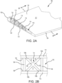
FIG. 2A illustrates a partial isometric view of an exemplary control surface, in accordance with various embodiments; -
FIG. 2B illustrates a cross-section view of a portion of the control surface ofFIG. 2A , in accordance with various embodiments; -
FIG. 3 illustrates a method of forming a fiber-reinforced control surface having stiffening structures, in accordance with various embodiments; -
FIG. 4 illustrates a part layup including a plurality of stiffening structure assemblies located in a mold tool, in accordance with various embodiments; -
FIGs. 5A and 5B illustrate a perspective view and a cross-section view, respectively, of a stiffening structure assembly, in accordance with various embodiments; -
FIG. 6 illustrates a perspective view of a mandrel for a stiffening structure assembly, in accordance with various embodiments; -
FIG. 7 illustrates a method of forming a stiffening structure assembly, in accordance with various embodiments; -
FIGs. 8A and 8B illustrate a perspective view and a cross-section view, respectively, of a fiber-mandrel section of a stiffening structure assembly, in accordance with various embodiments; -
FIGs. 8C and8D illustrate a perspective view and a cross-section view, respectively, of a fiber-mandrel assembly of a stiffening structure assembly, in accordance with various embodiments; and -
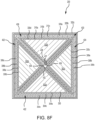
FIGs. 8E and8F illustrate a perspective view and a cross-section view, respectively, of a stiffening structure assembly, in accordance with various embodiments; - The detailed description of exemplary embodiments herein makes reference to the accompanying drawings, which show exemplary embodiments by way of illustration. While these exemplary embodiments are described in sufficient detail to enable those skilled in the art to practice the inventions, it should be understood that other embodiments may be realized and that logical changes and adaptations in design and construction may be made in accordance with this invention and the teachings herein. Thus, the detailed description herein is presented for purposes of illustration only and not for limitation. The scope of the invention is defined by the appended claims. For example, the steps recited in any of the method or process descriptions may be executed in any order and are not necessarily limited to the order presented. Furthermore, any reference to singular includes plural embodiments, and any reference to more than one component or step may include a singular embodiment or step. Also, any reference to attached, fixed, connected or the like may include permanent, removable, temporary, partial, full and/or any other possible attachment option. Surface shading lines may be used throughout the figures to denote different parts but not necessarily to denote the same or different materials.
- In general, the example control surfaces described herein may be used with aircraft wings, stabilizers, or elevators, among other aerodynamic surfaces of an aircraft. Some examples of common names for these surfaces known to those practiced in the arts include but are not limited to flaps, ailerons, rudders, elevators, stabilators, elevons, spoilers, lift dumpers, speed brakes, airbrakes, trim tabs, slats, flaperons, spoilerons, and canards. These are henceforth referred to as control surfaces. In general, control surfaces may direct air flow during maneuvering and in-flight aircraft attitude adjustments. The example control surfaces described herein include stiffening structures extending between the skins. The stiffening structures may thus increase the stiffness and/or the torsional strength and/or may resist greater loads in the fore and aft directions.
- A control surface, as described herein, includes a structural body comprising one or more stiffening structure(s) and skin members, wherein the stiffening structures are sandwiched between the skin members. In various embodiments, the skin members include a fiber reinforced material comprised of fiber/fabric and a resin (e.g., a thermoset resin). In various embodiments, the stiffening structures include a fiber reinforced material comprised of fiber/fabric and a resin (e.g., a thermoset resin). The reinforcing fiber used for the control surface has no particular limitations with respect to the type thereof, and examples thereof include metal fibers (e.g., aluminum fiber, brass fiber, copper fiber, etc.) carbon fibers, including graphite fibers (e.g., polyacrylonitrile (PAN)-based carbon fibers, rayon-based carbon fibers, lignin-based carbon fibers, and pitch-based carbon fibers), insulating fibers (e.g., glass fiber), organic fibers (e.g., aramid fibers, polyparaphenylene benzoxazole (PBO) fibers, polyphenylene sulfide fibers, polyester fibers, acrylic fibers, nylon fibers, and polyethylene fibers), and inorganic fibers (e.g., silicon carbide fibers and silicon nitride fibers). Fibers prepared by applying surface treatment to these fibers are also available. Examples of the surface treatment for fibers include treatment with a coupling agent, treatment with a sizing agent, treatment with a binder, and adhesion treatment with an additive in addition to deposition treatment with conductive metal. The thermoset resin may include a phenolic, methyl methacrryklate, epoxy, polyurethane, polyester, and/or any other suitable thermoset resin. To form the stiffening structure(s) and skin members, the fiber reinforced materials may be deposited using any suitable deposition method (e.g., hand layup, automated fiber placement (AFP), etc.).
- With reference to
FIG. 1 , anaircraft 10 having a variety of control surfaces disposed about thewings 12 and thetail section 14 of the aircraft is illustrated. The variety of control surfaces typically used on thewings 12 of theaircraft 10 may include, for example, an aileron 22, a trailingedge flap 24, aspoiler 26, disposed adjacent to and forward of the trailingedge flap 24, and aleading edge slat 28. Similarly, the variety of control surfaces typically used on thetail section 14 of theaircraft 10 may include, for example, arudder 30 and anelevator 32. - With reference to
FIG. 2A , a perspective view of acontrol surface 100 is illustrated in accordance with various embodiments.Control surface 100 may be employed as any of the control surfaces ofaircraft 10 inFIG. 1 (e.g., control surface may be an aileron 22, a trailingedge flap 24, aspoiler 26, aleading edge slat 28, arudder 30, an elevator 32). In various embodiments,control surface 100 may be a stabilator. - In accordance with various embodiments, the
control surface 100 comprises afirst skin 110, asecond skin 112, and one or more stiffening structure(s) 114 located betweenfirst skin 110 andsecond skin 112. Stated differently, achamber 116 may be formed between/defined by thefirst skin 110 and thesecond skin 112, and the stiffeningstructures 114 may be located in thechamber 116. Although illustrated as including four stiffeningstructures 114, any number of stiffeningstructures 114 may be utilized to form thecontrol surface 100, in accordance with various embodiments. Thefirst skin 110 and thesecond skin 112 may define anouter airfoil surface 117. In this regard,first skin 110 may form asuction side 118 ofcontrol surface 100,second skin 112 may form apressure side 120 ofcontrol surface 100, andfirst skin 110 may be joined withsecond skin 112 at aleading edge 122 and at a trailingedge 124 ofcontrol surface 100. - With reference to
FIG. 2B , additional details of astiffening structure 114 are illustrated. In accordance with various embodiments, stiffeningstructure 114 may include afirst leg 130 and a second leg 132. Each offirst leg 130 and second leg 132 extends between thefirst skin 110 and thesecond skin 112. In various embodiments,first leg 130 may be approximately perpendicular to second leg 132. In this regard, an angle theta (θ) formed between the adjacent surfaces offirst leg 130 and second leg 132 may be approximately 90°. As used in the previous context only, the term "approximately" means ± 5°. In accordance with various embodiments,first leg 130 and second leg 132 are each oriented at non-normal angles relative to the firstinterior surface 134 offirst skin 110 and the secondinterior surface 136 ofsecond skin 112. For example,first leg 130 may oriented at an angle beta (β) relative to firstinterior surface 134 offirst skin 110. Angle beta may be formed between firstinterior surface 134 and the surface offirst leg 130 that is adjacent to firstinterior surface 134. Angle beta may be between 15° and 75°, between 30° and 60°, and/or about 45°. As used in the previous context only, the term "about" means ± 5°. Second leg 132 may oriented at an angle delta (δ) relative to firstinterior surface 134 offirst skin 110. Angle delta may be formed between firstinterior surface 134 and the surface of second leg 132 that is adjacent to firstinterior surface 134. Angle delta may be between 15° and 75°, between 30° and 60°, and/or about 45°. As used in the previous context only, the term "about" means ± 5°. - In accordance with various embodiments, stiffening
structure 114 further includes a firstorthogonal leg 138 and a secondorthogonal leg 140. Firstorthogonal leg 138 extends between afirst end 130a offirst leg 130 and asecond end 132b of second leg 132. Secondorthogonal leg 140 extends between afirst end 132a of second leg 132 and asecond end 130b offirst leg 130.First end 130a offirst leg 130 andfirst end 132a of second leg 132 are each located at the firstinterior surface 134 offirst skin 110.Second end 130b offirst leg 130 andsecond end 132b of second leg 132 are each located at secondinterior surface 136 ofsecond skin 112. - With reference to
FIG. 3 , a method 150 for manufacturing a control surface is provided, in accordance with various embodiments. Method 150 includes forming one or more stiffening structure assembly(ies) comprising fiber and thermoset resin (step 152), stacking a plurality of first plies, comprising fiber and thermoset resin, to a desired thickness over a first tool (step 154). Method 150 further includes locating the stiffening structure assemblies over the first plies (step 156) and stacking a plurality of second plies, comprising fiber and thermoset resin, to a desired thickness over the stiffening structures to form a part layup (step 158). Method 150 further includes applying heat and pressure to the part layup (step 160). Step 160 may include curing the thermoset resin of the first plies, the thermoset resin of the stiffening structure assemblies, and the thermoset resin of the second plies. In this regard,step 160 may include heating the part layup to a temperature sufficient to melt the thermoset resin of the first plies, the thermoset resin of the stiffening structure assemblies, and the thermoset resin of the second plies and then cooling the part layup. After cooling, the thermoset resin of the first plies, the thermoset resin of the stiffening structure assemblies, and the thermoset resin of the second plies are bonded together (e.g., crosslinked). In this regard, after curing, the resin of one ply/layer may be indistinguishable from the resin of the adjacent ply/layer. After curing the thermoset resin of the first plies, stiffening structure assemblies, and the second plies, the mandrels, described in further detail below, may be removed from the stiffening structure assemblies (step 162). - With combined reference to
FIG. 3 andFIG. 4 , step 152 may include formingstiffening structure assemblies 200, as described in further detail below. Step 154 may include stacking a plurality offirst plies 202 over afirst mold tool 204. First plies 202 may located overfirst mold tool 204 using any suitable deposition process. First plies 202 may be stacked on afirst mold surface 206 offirst mold tool 204. In various embodiments, eachfirst ply 202 comprises a fiber sheet pre-impregnated with a thermoset resin. However, it is contemplated that various types of fiber and/or thermoset resin sheets may be used to form first plies 202. For example, the sheets may comprise pre-impregnated fibers and/or sheets of fibers interleaved with sheets of thermoset resin, among others. While threefirst plies 202 are illustrated, it is contemplated and understood that any number (one, five, ten, fifty, etc.) offirst plies 202 may be stacked. - Step 156 may include locating
stiffening structure assemblies 200 overfirst plies 202. In this regard,first plies 202 are located betweenfirst mold surface 206 and stiffeningstructure assemblies 200. Step 158 may include stacking a plurality ofsecond plies 208 over stiffeningstructure assemblies 200, thereby formingpart layup 210. Stiffeningstructure assemblies 200 are located betweenfirst plies 202 andsecond plies 208. In various embodiments, eachsecond ply 208 comprises a fiber sheet pre-impregnated with a thermoset resin. However, it is contemplated that various types of fiber and/or thermoset resin sheets may be used to form second plies 208. For example, the sheets may comprise pre-impregnated fibers and/or sheets of fibers interleaved with sheets of thermoset resin, among others. While threesecond plies 208 are illustrated, it is contemplated and understood that any number (one, five, ten, fifty, etc.) ofsecond plies 208 may be stacked. - In accordance with various embodiments,
part layup 210 includesfirst plies 202, stiffeningstructure assemblies 200, andsecond plies 208. Step 160 may include curingpart layup 210. For example, asecond mold tool 212 may be located overpart layup 210. Asecond mold surface 214 of second tool may be brought into contact withsecond plies 208. First andsecond mold tools step 160 may include heating first andsecond mold tools 204 212 to heatpart layup 210 to a temperature sufficient to melt the thermoset resin of each offirst plies 202, stiffeningstructure assemblies 200, andsecond plies 208. Addition resin may be injected betweenfirst mold tool 204 andsecond mold tool 212 during the RPM process. The injected resin applies pressure and/or increases a pressure applied topart layup 210. Duringstep 160, the thermoset resin of each of thefirst plies 202, the stiffeningstructure assemblies 200, and thesecond plies 208 is melted and then cooled. Upon cooling, thermoset resin of thefirst plies 202 crosslinks/bonds with the thermoset resin of the adjacentfirst plies 202 and stiffeningstructure assemblies 200. Upon cooling, the thermoset resin of thestiffening structure assemblies 200 crosslinks/bonds with the thermoset resin of the of the adjacentfirst plies 202, stiffeningstructure assemblies 200, andsecond plies 208. Upon cooling, the thermoset resin of thesecond plies 208 crosslinks/bonds with the thermoset resin of the of the adjacentstiffening structure assemblies 200 andsecond plies 208. Stated differently, duringstep 160, fiber reinforced material of each of thefirst plies 202, the stiffeningstructure assemblies 200, and thesecond plies 208 is consolidated with the fiber reinforced material of the adjacentfirst ply 202, stiffeningstructure assembly 200, and/orsecond ply 208. - In various embodiments, after curing (e.g., after step 160), the mandrels of the
stiffening structure assemblies 200, which are described in further detail below, are removed (step 162). In accordance with various embodiments,first plies 202 may form one offirst skin 110 andsecond skin 112 inFIG. 2A , andsecond plies 208 may form the other offirst skin 110 andsecond skin 112.First mold surface 206 may have a contour configured to formpressure side 120.Second mold surface 214 may have a contour configured to formsuction side 118. In this regard,first mold surface 206 andsecond mold surface 214 may together form/define the contouring of control surface 100 (FIG. 2A ). - With reference to
FIGs. 5A and 5B , a perspective view and a cross-section view, taken along theline 5B-5B inFIG. 5A , of a stiffeningstructure assembly 200 are illustrated, respectively. In accordance with various embodiments, stiffeningstructure assembly 200 may be employed to form one of the stiffeningstructures 114 inFIG. 2A . Stiffeningstructure assembly 200 includes a plurality of mandrels, such afirst mandrel 302a,second mandrel 302b,third mandrel 302c, andfourth mandrel 302d (collectively mandrels 302). One or more inner fiber layer(s) (or inner fiber plies) is wrapped (e.g., separately) around each offirst mandrel 302a,second mandrel 302b,third mandrel 302c, andfourth mandrel 302d. For example, first inner fiber plies 304a, 304b, and 304c (collectively first inner fiber plies 304) are located around and surround the perimeter offirst mandrel 302a. Second inner fiber plies 306a, 306b, and 306c (collectively second inner fiber plies 306) are located around and surround the perimeter ofsecond mandrel 302b. Third inner fiber plies 308a, 308b, and 308c (collectively third inner fiber plies 308) are located around and surround the perimeter ofthird mandrel 302c. Fourth inner fiber plies 310a, 310b, and 3 10c (collectively fourth inner fiber plies 310) are located around and surround the perimeter offourth mandrel 302d. WhileFIG. 5B illustrates three inner fiber plies formed around each offirst mandrel 302a,second mandrel 302b,third mandrel 302c, andfourth mandrel 302d, the present application is not limited in this manner. In this regard, any number (one, five, ten, fifty, etc.) of inner fiber plies may be formed around each offirst mandrel 302a,second mandrel 302b,third mandrel 302c, andfourth mandrel 302d. - In accordance various embodiments, one or more outer fiber layer(s) (or outer fiber plies), such as first
outer fiber ply 320a, secondouter fiber ply 320b, and thirdouter fiber ply 320c (collectively outer fiber plies 320) is/are wrapped aroundfirst mandrel 302a,second mandrel 302b,third mandrel 302c, andfourth mandrel 302d collectively. For example, firstouter fiber ply 320a may be located adjacent to the outermost inner fiber ply of each offirst mandrel 302a,second mandrel 302b,third mandrel 302c, andfourth mandrel 302d. Firstouter fiber ply 320a is located on and/or contacts inner fiber plies 304c, 306c, 308c, 310c. Secondouter fiber ply 320b is located around firstouter fiber 320a (i.e., firstouter fiber 320a is sandwiched between secondouter fiber ply 320b and the outermost inner fiber ply of each offirst mandrel 302a,second mandrel 302b,third mandrel 302c, andfourth mandrel 302d). Thirdouter fiber ply 320c is located around secondouter fiber ply 320b (i.e., secondouter fiber ply 320b is sandwiched between firstouter fiber ply 320a and thirdouter fiber ply 320c). WhileFIG. 5B illustrates three outer fiber plies, the present application is not limited in this manner. In this regard, any number (one, five, ten, fifty, etc.) of outer fiber plies 320 may be formed aroundfirst mandrel 302a,second mandrel 302b,third mandrel 302c, andfourth mandrel 302d collectively. - With reference to
FIG. 6 ,first mandrel 302a is illustrated. WhileFIG. 6 showsfirst mandrel 302a, it is contemplated and understood that each ofsecond mandrel 302b,third mandrel 302c, andfourth mandrel 302d may be similar tofirst mandrel 302a.First mandrel 302a may have a triangular prism shape. In this regard, afirst mandrel face 322 and asecond mandrel face 324 may each be a triangle, andfirst sidewall 326,second sidewall 328, andthird sidewall 330 may each be generally rectangular (e.g., a quadrilateral). Stated differently,first mandrel 302a has a triangle cross-section taken in a first plane (e.g., the X-Z plane) and a quadrilateral cross-section taken in a second plane, normal to the first plane (e.g., in the Y-Z and Y-X planes). In various embodiment, a height H and/or a width W offirst mandrel 302a may decrease betweenfirst mandrel face 322 andsecond mandrel face 324. This may allow forfirst mandrel 302a to be easily removed after curing (e.g., the removal ofstep 162 occurs after the curing ofstep 160 of method 150 inFIG. 3 ). In various embodiments,first mandrel 302a may be formed of a metallic material (e.g., a metal or metal alloy) such as aluminum, stainless steel, titanium, nickel-based alloy, etc. The metallic material may thermally expand during curing of the part layup (e.g., during step 160), the thermal expansion applying an outward force to the fiber plies (e.g., forces the fiber plies toward the mold surfaces. - With reference to
FIG. 7 , a method 400 for forming a stiffening structure assembly, such as stiffeningstructure assembly 200 inFIGs. 5A and 5B , is illustrated. In accordance with various embodiments, method 400 includes depositing one or more first inner fiber ply(ies) around a first mandrel to form a first fiber-mandrel section (step 402), depositing one or more second inner fiber ply(ies) around a second mandrel to form a second fiber-mandrel section (step 404), depositing one or more third inner fiber ply(ies) around a third mandrel to form a third fiber-mandrel section (step 406) and depositing one or more fourth inner fiber ply(ies) around a fourth mandrel to form a fourth fiber-mandrel section (step 408). Method 400 may further include locating each of the second, third, and fourth fiber-mandrel sections over the first fiber-mandrel section (step 410) to form a fiber-mandrel assembly and depositing one or more outer fiber ply(ies) around the fiber-mandrel assembly (step 412). - With reference to
FIG. 7 andFIGs. 8A and 8B ,step 402 may include depositing first inner fiber plies 304a, 304b, 304c aroundfirst mandrel 302a to form a first fiber-mandrel section 420. In various embodiments, first inner fiber plies 304a, 304b, 304c may be utilized to deposited using AFP. However, the disclosure is not limited in this regard, and other fiber deposition operations (e.g., hand layup) may be employed to deposit the inner fiber plies 304a, 304b, 304c aboutfirst mandrel 302a. First inner fiber plies 304a, 304b, 304c may be deposited over first, second, andthird sidewalls first mandrel 302a. In various embodiments, each of firstinner fiber ply third sidewalls inner fiber ply 304a may be located on (e.g., in contact with) first, second, andthird sidewalls inner fiber ply 304b is located on firstinner fiber ply 304a. Firstinner fiber ply 304c is located on firstinner fiber ply 304c. Firstinner fiber ply 304c may form the outermost inner ply of first fiber-mandrel section 420. - In various embodiments, first inner fiber plies 304a, 304b, 304c may be part of one continuous fiber strip/fiber sheet. In this regard,
inner fiber ply 304a may be applied by beginning the wrapping ofinner fiber ply 304a around first, second, andthird sidewalls first mandrel face 322 and proceeding with wrappinginner fiber ply 304a around first, second, andthird sidewalls second mandrel face 324.Inner fiber ply 304b is then deposited overinner fiber ply 304a by beginning the wrapping ofinner fiber ply 304b over first, second, andthird sidewalls inner fiber ply 304a) proximatesecond mandrel face 324 and proceeding towardsfirst mandrel face 322 while wrapping first innerfiber ply layer 304b around first, second, andthird sidewalls fiber ply layer 304c is then deposited over innerfiber ply layer 304b by beginning the wrapping ofinner fiber layer 304c over first, second, andthird sidewalls fiber ply layer 304b) proximatefirst mandrel face 322 and proceeding towardssecond mandrel face 324 while wrappinginner fiber ply 304c around first, second, andthird sidewalls inner fiber ply 304a may be discrete from (e.g., non-continuous with) firstinner fiber layer 304b and firstinner fiber layer 304c. In various embodiments, the fiber angles may be varied alongfirst mandrel 302a. For example, the angle of the fibers located proximatefirst mandrel face 322 may be different from the angle of the fibers located proximatesecond mandrel face 324. In various embodiments, the angle of the fibers formed onfirst sidewall 326 may be different from the angle of the fibers located onsecond sidewall 328 and/or onthird sidewall 330. In this regard, the orientation of the fibers of first inner fiber plies 304a, 304b, 304c may be selected to tailor the stiffness and/or torsional strength of stiffening structure 114 (FIG. 2A ). - First inner fiber plies 304a, 304b, 304c comprise a fiber sheet pre-impregnated with a thermoset resin. However, it is contemplated that various types of fiber and/or thermoset resin sheets may be used for first inner fiber plies 304. For example, the sheets may comprise pre-impregnated fibers and/or sheets of fibers interleaved with sheets of thermoset resin, among others. While
FIG. 8B illustrates three first inner fiber plies formed aroundfirst mandrel 302a, the present application is not limited in this manner. In this regard, first fiber-mandrel section 420 may include any number (one, five, ten, fifty, etc.) of first inner fiber plies formed aroundfirst mandrel 302a. - With reference to
FIG. 7 andFIGs. 8C and8D ,step 404 may include depositing second inner fiber plies 306a, 306b, 306c aroundsecond mandrel 302b to form a second fiber-mandrel section 422. In this regard,step 404 may be similar to step 402, as described above. Step 406 may include depositing third inner fiber plies 308a, 308b, 308c aroundthird mandrel 302c to form a third fiber-mandrel section 424. In this regard,step 406 may be similar to step 402, as described above. Step 408 may include depositing fourth inner fiber plies 310a, 310b, 310c aroundfourth mandrel 302d to form a fourth fiber-mandrel section 426. In this regard,step 408 may be similar to step 402, as described above. - Step 410 may include stacking second fiber-
mandrel section 422, third fiber-mandrel section 424, and fourth fiber-mandrel section 426 over first fiber-mandrel section 420 to form a fiber-mandrel assembly 430. In this regard, fiber-mandrel assembly 430 includes first fiber-mandrel section 420, second fiber-mandrel section 422, third fiber-mandrel section 424, and fourth fiber-mandrel section 426. -
Second sidewall 328b ofsecond mandrel 302b may be located on and oriented towardfirst sidewall 326 offirst mandrel 302a.Second sidewall 328d offourth mandrel 302d may be located on and oriented towardfirst sidewall 326b ofsecond mandrel 302b.First sidewall 326d offourth mandrel 302d may be located on and oriented towardsecond sidewall 328c ofthird mandrel 302c.First sidewall 326c ofthird mandrel 302c may be located on and oriented towardsecond sidewall 328 offirst mandrel 302a. First inner fiber plies 304a, 304b, 304c and secondinner plies second sidewall 328b ofsecond mandrel 302b andfirst sidewall 326 offirst mandrel 302a. Secondinner plies inner plies first sidewall 326b ofsecond mandrel 302b andsecond sidewall 328d offourth mandrel 302d. Thirdinner plies inner plies first sidewall 326d offourth mandrel 302d andsecond sidewall 328c ofthird mandrel 302c. Thirdinner plies first sidewall 326c ofthird mandrel 302c andsecond sidewall 328 offirst mandrel 302a. The outermost firstinner fiber layer 304c of first fiber-mandrel section 420 may be adj acent to the outermost secondinner fiber layer 306c of second fiber-mandrel section 422 and the outermost thirdinner fiber layer 308c of third fiber-mandrel section 424. The outermost fourthinner fiber layer 310c of fourth fiber-mandrel section 426 is adjacent to the outermost secondinner fiber layer 306c of second fiber-mandrel section 422 and the outermost thirdinner fiber layer 308c of third fiber-mandrel section 424. Thethird sidewalls first mandrel 302a,second mandrel 302b,third mandrel 302c, andfourth mandrel 302d, respectively, are oriented outward and form an outer mandrel perimeter. Stated differently, the firstinner fiber ply 304c located onthird sidewall 330, the secondinner fiber ply 306c located onthird sidewall 330b, the fourthinner fiber ply 310c located onthird sidewall 330d and the thirdinner fiber ply 308c located onthird sidewall 330c form an outer perimeter of fiber-mandrel assembly 430. - In accordance with various embodiments, a fiber bundle, or "noodle", 431 may be located at the center of fiber-
mandrel assembly 430. In this regard,fiber bundle 431 may located between the apex 432 (first apex) of first fiber-mandrel section 420, the apex 434 (second apex) of second fiber-mandrel section 422, the apex 436 (third apex) of third fiber-mandrel section 424, and the apex 438 (fourth apex) of fourth fiber-mandrel section 426.Fiber bundle 431 may help to fill the void formed between first apex 432,second apex 434,third apex 436, andfourth apex 438. - With additional reference to
FIGs. 8E and8F , step 412 may include depositing outer fiber plies 320a, 320b, 320c around the fiber-mandrel assembly 430 to form stiffeningstructure assembly 200. Stated differently, outer fiber plies 320a, 320b, 320c are deposited adjacent to and/or on the outermost inner fiber ply of each of first fiber-mandrel section 420, second fiber-mandrel section 422, third fiber-mandrel section 424, and fourth fiber-mandrel section 426. Outer fiber plies 320a, 320b, 320c may be deposited using AFP. However, the disclosure is not limited in this regard, and other fiber deposition operations (e.g., hand layup) may be employed to deposit the outer fiber plies 320a, 320b, 320c about the fiber-mandrel assembly 430. Firstouter fiber ply 320a may be deposited over and/or on the firstinner fiber ply 304c located onthird sidewall 330, the secondinner fiber ply 306c located onthird sidewall 330b, the fourthinner fiber ply 310c located onthird sidewall 330d, and the thirdinner fiber ply 308c located onthird sidewall 330c. Secondouter fiber ply 320b may be deposited on firstouter fiber ply 320a. Thirdouter fiber ply 320c may be deposited on secondouter fiber ply 320b. Outer fiber plies 320a,320b 320c may each comprise a fiber sheet pre-impregnated with a thermoset resin. However, it is contemplated that various types of fiber and/or thermoset resin sheets may be used to form outer fiber plies 320a, 320b 320c. For example, the sheets may comprise pre-impregnated fibers and/or sheets of fibers interleaved with sheets of thermoset resin, among others. In various embodiments, outer fiber plies 320a,320b 320c may comprise a continuous fiber strip. - In accordance with various embodiments, the inner fiber plies 304, 306, 308, 310 and outer fiber plies 320 are not formed on the mandrel faces 322, 324. This allows the first, second, third, and
fourth mandrels step 160 of method 150 inFIG. 3 ). In this regard, thefirst mandrel face 322 and thesecond mandrel face 324 of each first, second, third, andfourth mandrels - Benefits, other advantages, and solutions to problems have been described herein with regard to specific embodiments. Furthermore, the connecting lines shown in the various figures contained herein are intended to represent exemplary functional relationships and/or physical couplings between the various elements. It should be noted that many alternative or additional functional relationships or physical connections may be present in a practical system. However, the benefits, advantages, solutions to problems, and any elements that may cause any benefit, advantage, or solution to occur or become more pronounced are not to be construed as critical, required, or essential features or elements of the inventions. The scope of the inventions is accordingly to be limited by nothing other than the appended claims, in which reference to an element in the singular is not intended to mean "one and only one" unless explicitly so stated, but rather "one or more." Moreover, where a phrase similar to "at least one of A, B, or C" is used in the claims, it is intended that the phrase be interpreted to mean that A alone may be present in an embodiment, B alone may be present in an embodiment, C alone may be present in an embodiment, or that any combination of the elements A, B and C may be present in a single embodiment; for example, A and B, A and C, B and C, or A and B and C. Different cross-hatching is used throughout the figures to denote different parts but not necessarily to denote the same or different materials.
- Systems, methods, and apparatus are provided herein. In the detailed description herein, references to "one embodiment," "an embodiment," "an example embodiment," etc., indicate that the embodiment described may include a particular feature, structure, or characteristic, but every embodiment may not necessarily include the particular feature, structure, or characteristic. Moreover, such phrases are not necessarily referring to the same embodiment. Further, when a particular feature, structure, or characteristic is described in connection with an embodiment, it is submitted that it is within the knowledge of one skilled in the art to affect such feature, structure, or characteristic in connection with other embodiments whether or not explicitly described. After reading the description, it will be apparent to one skilled in the relevant art(s) how to implement the disclosure in alternative embodiments. Furthermore, no element, component, or method step in the present disclosure is intended to be dedicated to the public regardless of whether the element, component, or method step is explicitly recited in the claims. No claim element is intended to invoke 35 U.S.C. 112(f) unless the element is expressly recited using the phrase "means for." As used herein, the terms "comprises," "comprising," or any other variation thereof, are intended to cover a non-exclusive inclusion, such that a process, method, article, or apparatus that comprises a list of elements does not include only those elements but may include other elements not expressly listed or inherent to such process, method, article, or apparatus.
Claims (15)
- A method for forming a stiffening structure assembly (200) for making a fiber-reinforced control surface (100), comprising:forming a plurality of fiber-mandrel sections (420, 422, 424, 426);stacking the plurality of fiber-mandrel sections (420, 422, 424, 426) to form a fiber-mandrel assembly (430); anddepositing an outer fiber ply (320a, 320b, 320c) around a perimeter of the fiber-mandrel assembly (430).
- The method of claim 1, wherein forming the plurality of fiber-mandrel sections (420, 422, 424, 426) comprises:forming a first fiber-mandrel section (420);forming a second fiber-mandrel section (422);forming a third fiber-mandrel section (424); andforming a fourth fiber-mandrel section (426).
- The method of claim 2, wherein forming the first fiber-mandrel section (420) comprises depositing a first inner fiber ply (304a) around a perimeter of a first mandrel (302a), and wherein forming the second fiber-mandrel section (422) comprises depositing a second inner fiber ply (306a) around a perimeter of a second mandrel (302b), and wherein forming the third fiber-mandrel section (424) comprises depositing a third inner fiber ply (308a) around a perimeter of a third mandrel (302c), and wherein forming the fourth fiber-mandrel section (426) comprises depositing a fourth inner fiber ply (3 10a) around a perimeter of a fourth mandrel (302d).
- The method of claim 3, further comprising locating a fiber bundle (431) in a void formed between a first apex (432) of the first fiber-mandrel section (420), a second apex (434) of the second fiber-mandrel section (422), a third apex (436) of the third fiber-mandrel section (424), and a fourth apex (438) of the fourth fiber-mandrel section (426).
- The method of claim 3 or 4, wherein:each of the first mandrel (302a), the second mandrel (302b), the third mandrel (302c), and the fourth mandrel (302d) has a triangular prism shape; and/orat least one of a first height (H) or a first width (W) of the first mandrel (302a) as measured at a first mandrel face (322) of the first mandrel (302a) is less than a second height (H) or a second width (W) of the first mandrel (302a) as measured at a second mandrel face (324) of the first mandrel (302a).
- A method for forming a fiber-reinforced control surface (100), comprising:forming a part layup (210) over a first mold surface (206) by:locating a first fiber ply (202) over the first mold surface (206);locating a plurality of stiffening structure assemblies (200) over the first fiber ply (202); andlocating a second fiber ply (208) over the plurality of stiffening structure assemblies (200);contacting the second fiber ply (208) with a second mold surface (214); andcuring the part layup (210) by applying heat and pressure to the part layup (210).
- The method of claim 6, further comprising forming each stiffening structure assembly (200) of the plurality of stiffening structure assemblies (200) by:forming a plurality of fiber-mandrel sections (420, 422, 424, 426);stacking the plurality of fiber-mandrel sections (420, 422, 424, 426) to form a fiber-mandrel assembly (430); anddepositing an outer fiber ply (320a, 320b, 320c) around a perimeter of the fiber-mandrel assembly (430).
- The method of claim 7, wherein forming the plurality of fiber-mandrel sections (420, 422, 424, 426) comprises:forming a first fiber-mandrel section (420);forming a second fiber-mandrel section (422);forming a third fiber-mandrel section (424); andforming a fourth fiber-mandrel section (426).
- The method of claim 8, wherein forming the first fiber-mandrel section (420) comprises depositing a first inner fiber ply (304a) around a perimeter of a first mandrel (302a), and wherein forming the second fiber-mandrel section (422) comprises depositing a second inner fiber ply (306a) around a perimeter of a second mandrel (302b), and wherein forming the third fiber-mandrel section (424) comprises depositing a third inner fiber ply (308a) around a perimeter of a third mandrel (302c), and wherein forming the fourth fiber-mandrel section (426) comprises depositing a fourth inner fiber ply (310a) around a perimeter of a fourth mandrel (302d), and, optionally, each of the first mandrel (302a), the second mandrel (302b), the third mandrel (302c), and the fourth mandrel (302d) has a triangular prism shape.
- The method of claim 9, further comprising:removing the first mandrel (302a), the second mandrel (302b), the third mandrel (302c), and the fourth mandrel (302d) from each stiffening structure assembly (200) of the plurality of stiffening structure assemblies (200) after curing the part layup (210); and/orlocating a fiber bundle (431) in a void formed between a first apex (432) of the first fiber-mandrel section (420), a second apex (434) of the second fiber-mandrel section (422), a third apex (436) of the third fiber-mandrel section (424), and a fourth apex (438) of the fourth fiber-mandrel section (426).
- The method of claim 8, 9 or 10, wherein curing the part layup (210) by applying heat and pressure to the part layup (210) comprises:crosslinking a first resin of the first fiber-mandrel section (420) with a second resin of the second fiber-mandrel section (422) and with a third resin of the third fiber-mandrel section (424);crosslinking the second resin of the second fiber-mandrel section (422) with a fourth resin of the fourth fiber-mandrel section (426); andcrosslinking the fourth resin of the fourth fiber-mandrel section (426) with the third resin of the third fiber-mandrel section (424).
- The method of any of claims 6 to 11, wherein curing the part layup (210) by applying heat and pressure to the part layup (210) comprises heating the part layup (210) to a temperature sufficient to consolidate a first thermoset resin of the first fiber ply (202) with a second thermoset resin of the plurality of stiffening structure assemblies (200) and to consolidate the second thermoset resin of the plurality of stiffening structure assemblies (200) with a third thermoset resin of the second fiber ply (208).
- A control surface (100) for an aircraft, the control surface (100) comprising:a first skin (110);a second skin (112) bonded to the first skin (110); anda plurality of stiffening structures (114) located between the first skin (110) and the second skin (112), wherein each stiffening structure (114) of the plurality of stiffening structures (114) includes a first leg (130) extending between the first skin (110) and the second skin (112) and a second leg (132) extending between the first skin (110) and the second skin (112).
- The control surface (100) of claim 13, wherein:the first leg (130) is approximately perpendicular to the second leg (132); and/orthe first leg (130) is oriented at a first angle (β) relative to a first interior surface (134) of the first skin (110), and wherein the second leg (132) is oriented at a second angle (δ) relative to the first interior surface (134) of the first skin (110), wherein each of the first angle (β) and the second angle (δ) is between 30° and 60°, and, optionally, each stiffening structure (114) of the plurality of stiffening structures (114) further includes a first orthogonal leg (138) and a second orthogonal leg (140), the first orthogonal leg (138) extending between a first end (130a) of the first leg (130) and a second end (132b) of the second leg (132), the second orthogonal leg (140) extending between a first end (132a) of the second leg (132) and a second end (130b) of the first leg (130), the first end (130a, 132a) of the each of the first leg (130) and the second leg (132) being located at the first interior surface (134) of the first skin (110), the second end (130b, 132b) of the each of the first leg (130) and the second leg (132) being located at a second interior surface (136) of the second skin (112).
- The control surface (100) of claim 13 or 14, wherein a first thermoset resin of the first skin (110) is crosslinked with a second thermoset resin of the plurality of stiffening structures (114), and wherein the second thermoset resin of the plurality of stiffening structures (114) is crosslinked with a third thermoset resin of the second skin (112).
Applications Claiming Priority (1)
| Application Number | Priority Date | Filing Date | Title |
|---|---|---|---|
| US17/717,056 US20230321928A1 (en) | 2022-04-09 | 2022-04-09 | Composite part with crossbeam supports and methods of forming composite parts |
Publications (2)
| Publication Number | Publication Date |
|---|---|
| EP4257347A1 true EP4257347A1 (en) | 2023-10-11 |
| EP4257347B1 EP4257347B1 (en) | 2025-12-10 |
Family
ID=85792067
Family Applications (1)
| Application Number | Title | Priority Date | Filing Date |
|---|---|---|---|
| EP23165559.8A Active EP4257347B1 (en) | 2022-04-09 | 2023-03-30 | Composite part with crossbeam supports and methods of forming composite parts |
Country Status (2)
| Country | Link |
|---|---|
| US (1) | US20230321928A1 (en) |
| EP (1) | EP4257347B1 (en) |
Citations (6)
| Publication number | Priority date | Publication date | Assignee | Title |
|---|---|---|---|---|
| US4223053A (en) * | 1978-08-07 | 1980-09-16 | The Boeing Company | Truss core panels |
| JPH02155633A (en) * | 1988-12-07 | 1990-06-14 | Fuji Heavy Ind Ltd | Preparation of truss structure made of fiber reinforced plastic |
| US5332178A (en) * | 1992-06-05 | 1994-07-26 | Williams International Corporation | Composite wing and manufacturing process thereof |
| WO1999004964A1 (en) * | 1997-07-25 | 1999-02-04 | Tpi Technology, Inc. | Large composite core structures formed by vacuum assisted resin transfer molding |
| EP1459873A2 (en) * | 2003-03-20 | 2004-09-22 | The Boeing Company | Molding process and apparatus for producing unified composite structures |
| EP2947001A1 (en) * | 2014-05-19 | 2015-11-25 | The Boeing Company | Method for fabricating a composite truss structure, and the resulting composite truss structure |
Family Cites Families (3)
| Publication number | Priority date | Publication date | Assignee | Title |
|---|---|---|---|---|
| US1389143A (en) * | 1919-01-25 | 1921-08-30 | Westinghouse Electric & Mfg Co | Reinforced tube and method of making it |
| US3028292A (en) * | 1957-05-27 | 1962-04-03 | Parsons Corp | Method of manufacturing plastic rotor blades |
| US6918839B2 (en) * | 2002-01-28 | 2005-07-19 | The Boeing Company | Damage tolerant shaft |
-
2022
- 2022-04-09 US US17/717,056 patent/US20230321928A1/en not_active Abandoned
-
2023
- 2023-03-30 EP EP23165559.8A patent/EP4257347B1/en active Active
Patent Citations (6)
| Publication number | Priority date | Publication date | Assignee | Title |
|---|---|---|---|---|
| US4223053A (en) * | 1978-08-07 | 1980-09-16 | The Boeing Company | Truss core panels |
| JPH02155633A (en) * | 1988-12-07 | 1990-06-14 | Fuji Heavy Ind Ltd | Preparation of truss structure made of fiber reinforced plastic |
| US5332178A (en) * | 1992-06-05 | 1994-07-26 | Williams International Corporation | Composite wing and manufacturing process thereof |
| WO1999004964A1 (en) * | 1997-07-25 | 1999-02-04 | Tpi Technology, Inc. | Large composite core structures formed by vacuum assisted resin transfer molding |
| EP1459873A2 (en) * | 2003-03-20 | 2004-09-22 | The Boeing Company | Molding process and apparatus for producing unified composite structures |
| EP2947001A1 (en) * | 2014-05-19 | 2015-11-25 | The Boeing Company | Method for fabricating a composite truss structure, and the resulting composite truss structure |
Also Published As
| Publication number | Publication date |
|---|---|
| US20230321928A1 (en) | 2023-10-12 |
| EP4257347B1 (en) | 2025-12-10 |
Similar Documents
| Publication | Publication Date | Title |
|---|---|---|
| US10836472B2 (en) | One-piece composite bifurcated winglet | |
| EP3858584B1 (en) | Thermoplastic composite panel systems and methods | |
| KR100311562B1 (en) | Fiber reinforced composite spar for a rotary wing aircraft and method of manufacture thereof | |
| EP3301014B1 (en) | Airfoil-shaped body having composite base skin with integral hat-shaped spar | |
| CN102712144B (en) | Dual-skin structures | |
| EP2698317B1 (en) | Composite wing slat for aircraft | |
| EP2814731B1 (en) | Reinforced composite structures for aircrafts and methods for making the same | |
| EP3536488B1 (en) | Preform figuring method and composite material shaping method | |
| WO2017027087A1 (en) | Trailing edge components, aircraft structures including trailing edge components and methods for manufacturing trailing edge components | |
| JP5319538B2 (en) | Wing panel structure | |
| US20140023830A1 (en) | Method of manufacturing a structure | |
| EP4257347B1 (en) | Composite part with crossbeam supports and methods of forming composite parts | |
| JP7236337B2 (en) | Composite material wing and molding method for composite material wing | |
| EP1595787B1 (en) | Method for fabricating a composite material control surface for an aircraft. | |
| EP4144515A1 (en) | Thermoplastic composite panel with corrugated peaks and troughs stiffening systems and methods | |
| EP3970954B1 (en) | Composite laminate for an airframe lifting surface and method for manufacturing thereof | |
| EP4147965B1 (en) | Aircraft control surface having variable height corrugated core | |
| EP4212435B1 (en) | Lightning strike protection layer | |
| US12151812B2 (en) | Resin pressure molded aerostructure with integrated metal coupling | |
| US20240003329A1 (en) | Composite thermoplastic rotor blade with integral cuff | |
| EP3812137A1 (en) | Composite laminate for an airframe lifting surface and method for manufacturing thereof |
Legal Events
| Date | Code | Title | Description |
|---|---|---|---|
| PUAI | Public reference made under article 153(3) epc to a published international application that has entered the european phase |
Free format text: ORIGINAL CODE: 0009012 |
|
| STAA | Information on the status of an ep patent application or granted ep patent |
Free format text: STATUS: THE APPLICATION HAS BEEN PUBLISHED |
|
| AK | Designated contracting states |
Kind code of ref document: A1 Designated state(s): AL AT BE BG CH CY CZ DE DK EE ES FI FR GB GR HR HU IE IS IT LI LT LU LV MC ME MK MT NL NO PL PT RO RS SE SI SK SM TR |
|
| STAA | Information on the status of an ep patent application or granted ep patent |
Free format text: STATUS: REQUEST FOR EXAMINATION WAS MADE |
|
| 17P | Request for examination filed |
Effective date: 20240411 |
|
| RBV | Designated contracting states (corrected) |
Designated state(s): AL AT BE BG CH CY CZ DE DK EE ES FI FR GB GR HR HU IE IS IT LI LT LU LV MC ME MK MT NL NO PL PT RO RS SE SI SK SM TR |
|
| STAA | Information on the status of an ep patent application or granted ep patent |
Free format text: STATUS: EXAMINATION IS IN PROGRESS |
|
| 17Q | First examination report despatched |
Effective date: 20240909 |
|
| GRAP | Despatch of communication of intention to grant a patent |
Free format text: ORIGINAL CODE: EPIDOSNIGR1 |
|
| STAA | Information on the status of an ep patent application or granted ep patent |
Free format text: STATUS: GRANT OF PATENT IS INTENDED |
|
| INTG | Intention to grant announced |
Effective date: 20250704 |
|
| GRAS | Grant fee paid |
Free format text: ORIGINAL CODE: EPIDOSNIGR3 |
|
| GRAA | (expected) grant |
Free format text: ORIGINAL CODE: 0009210 |
|
| STAA | Information on the status of an ep patent application or granted ep patent |
Free format text: STATUS: THE PATENT HAS BEEN GRANTED |
|
| AK | Designated contracting states |
Kind code of ref document: B1 Designated state(s): AL AT BE BG CH CY CZ DE DK EE ES FI FR GB GR HR HU IE IS IT LI LT LU LV MC ME MK MT NL NO PL PT RO RS SE SI SK SM TR |
|
| REG | Reference to a national code |
Ref country code: CH Ref legal event code: F10 Free format text: ST27 STATUS EVENT CODE: U-0-0-F10-F00 (AS PROVIDED BY THE NATIONAL OFFICE) Effective date: 20251210 Ref country code: GB Ref legal event code: FG4D |
|
| REG | Reference to a national code |
Ref country code: DE Ref legal event code: R096 Ref document number: 602023009433 Country of ref document: DE |
|
| REG | Reference to a national code |
Ref country code: IE Ref legal event code: FG4D |
|
| PG25 | Lapsed in a contracting state [announced via postgrant information from national office to epo] |
Ref country code: ES Free format text: LAPSE BECAUSE OF FAILURE TO SUBMIT A TRANSLATION OF THE DESCRIPTION OR TO PAY THE FEE WITHIN THE PRESCRIBED TIME-LIMIT Effective date: 20251210 |
|
| REG | Reference to a national code |
Ref country code: LT Ref legal event code: MG9D |
|
| PG25 | Lapsed in a contracting state [announced via postgrant information from national office to epo] |
Ref country code: NO Free format text: LAPSE BECAUSE OF FAILURE TO SUBMIT A TRANSLATION OF THE DESCRIPTION OR TO PAY THE FEE WITHIN THE PRESCRIBED TIME-LIMIT Effective date: 20260310 |
|
| PGFP | Annual fee paid to national office [announced via postgrant information from national office to epo] |
Ref country code: DE Payment date: 20260219 Year of fee payment: 4 |
|
| PG25 | Lapsed in a contracting state [announced via postgrant information from national office to epo] |
Ref country code: FI Free format text: LAPSE BECAUSE OF FAILURE TO SUBMIT A TRANSLATION OF THE DESCRIPTION OR TO PAY THE FEE WITHIN THE PRESCRIBED TIME-LIMIT Effective date: 20251210 Ref country code: HR Free format text: LAPSE BECAUSE OF FAILURE TO SUBMIT A TRANSLATION OF THE DESCRIPTION OR TO PAY THE FEE WITHIN THE PRESCRIBED TIME-LIMIT Effective date: 20251210 |
|
| PGFP | Annual fee paid to national office [announced via postgrant information from national office to epo] |
Ref country code: AT Payment date: 20260301 Year of fee payment: 4 |
|
| REG | Reference to a national code |
Ref country code: NL Ref legal event code: MP Effective date: 20251210 |
|
| PG25 | Lapsed in a contracting state [announced via postgrant information from national office to epo] |
Ref country code: RS Free format text: LAPSE BECAUSE OF FAILURE TO SUBMIT A TRANSLATION OF THE DESCRIPTION OR TO PAY THE FEE WITHIN THE PRESCRIBED TIME-LIMIT Effective date: 20260310 |
|
| PGFP | Annual fee paid to national office [announced via postgrant information from national office to epo] |
Ref country code: FR Payment date: 20260219 Year of fee payment: 4 |
|
| PG25 | Lapsed in a contracting state [announced via postgrant information from national office to epo] |
Ref country code: LV Free format text: LAPSE BECAUSE OF FAILURE TO SUBMIT A TRANSLATION OF THE DESCRIPTION OR TO PAY THE FEE WITHIN THE PRESCRIBED TIME-LIMIT Effective date: 20251210 |
|
| PG25 | Lapsed in a contracting state [announced via postgrant information from national office to epo] |
Ref country code: BG Free format text: LAPSE BECAUSE OF FAILURE TO SUBMIT A TRANSLATION OF THE DESCRIPTION OR TO PAY THE FEE WITHIN THE PRESCRIBED TIME-LIMIT Effective date: 20251210 |