EP4257346A1 - Mixing device, bottle unit, and puncture repair kit - Google Patents
Mixing device, bottle unit, and puncture repair kit Download PDFInfo
- Publication number
- EP4257346A1 EP4257346A1 EP23155938.6A EP23155938A EP4257346A1 EP 4257346 A1 EP4257346 A1 EP 4257346A1 EP 23155938 A EP23155938 A EP 23155938A EP 4257346 A1 EP4257346 A1 EP 4257346A1
- Authority
- EP
- European Patent Office
- Prior art keywords
- mixing device
- inlet
- puncture repair
- flow direction
- mixing chamber
- Prior art date
- Legal status (The legal status is an assumption and is not a legal conclusion. Google has not performed a legal analysis and makes no representation as to the accuracy of the status listed.)
- Pending
Links
- 230000008439 repair process Effects 0.000 title claims abstract description 69
- 239000007788 liquid Substances 0.000 claims abstract description 49
- 239000000203 mixture Substances 0.000 claims abstract description 16
- 238000007599 discharging Methods 0.000 claims abstract description 5
- LYCAIKOWRPUZTN-UHFFFAOYSA-N Ethylene glycol Chemical compound OCCO LYCAIKOWRPUZTN-UHFFFAOYSA-N 0.000 claims description 9
- 239000000443 aerosol Substances 0.000 claims description 4
- WGCNASOHLSPBMP-UHFFFAOYSA-N hydroxyacetaldehyde Natural products OCC=O WGCNASOHLSPBMP-UHFFFAOYSA-N 0.000 claims description 3
- 238000010586 diagram Methods 0.000 description 9
- 238000007789 sealing Methods 0.000 description 4
- DNIAPMSPPWPWGF-UHFFFAOYSA-N Propylene glycol Chemical compound CC(O)CO DNIAPMSPPWPWGF-UHFFFAOYSA-N 0.000 description 3
- 239000011358 absorbing material Substances 0.000 description 2
- 230000008859 change Effects 0.000 description 2
- DNIAPMSPPWPWGF-VKHMYHEASA-N (+)-propylene glycol Chemical compound C[C@H](O)CO DNIAPMSPPWPWGF-VKHMYHEASA-N 0.000 description 1
- YPFDHNVEDLHUCE-UHFFFAOYSA-N 1,3-propanediol Substances OCCCO YPFDHNVEDLHUCE-UHFFFAOYSA-N 0.000 description 1
- 235000006679 Mentha X verticillata Nutrition 0.000 description 1
- 235000002899 Mentha suaveolens Nutrition 0.000 description 1
- 235000001636 Mentha x rotundifolia Nutrition 0.000 description 1
- 230000008901 benefit Effects 0.000 description 1
- 230000006866 deterioration Effects 0.000 description 1
- 150000002334 glycols Chemical class 0.000 description 1
- 238000000034 method Methods 0.000 description 1
- 229920000166 polytrimethylene carbonate Polymers 0.000 description 1
- 230000008569 process Effects 0.000 description 1
- 230000010349 pulsation Effects 0.000 description 1
Images


Classifications
-
- B—PERFORMING OPERATIONS; TRANSPORTING
- B29—WORKING OF PLASTICS; WORKING OF SUBSTANCES IN A PLASTIC STATE IN GENERAL
- B29C—SHAPING OR JOINING OF PLASTICS; SHAPING OF MATERIAL IN A PLASTIC STATE, NOT OTHERWISE PROVIDED FOR; AFTER-TREATMENT OF THE SHAPED PRODUCTS, e.g. REPAIRING
- B29C73/00—Repairing of articles made from plastics or substances in a plastic state, e.g. of articles shaped or produced by using techniques covered by this subclass or subclass B29D
- B29C73/02—Repairing of articles made from plastics or substances in a plastic state, e.g. of articles shaped or produced by using techniques covered by this subclass or subclass B29D using liquid or paste-like material
-
- B—PERFORMING OPERATIONS; TRANSPORTING
- B29—WORKING OF PLASTICS; WORKING OF SUBSTANCES IN A PLASTIC STATE IN GENERAL
- B29C—SHAPING OR JOINING OF PLASTICS; SHAPING OF MATERIAL IN A PLASTIC STATE, NOT OTHERWISE PROVIDED FOR; AFTER-TREATMENT OF THE SHAPED PRODUCTS, e.g. REPAIRING
- B29C73/00—Repairing of articles made from plastics or substances in a plastic state, e.g. of articles shaped or produced by using techniques covered by this subclass or subclass B29D
- B29C73/16—Auto-repairing or self-sealing arrangements or agents
- B29C73/166—Devices or methods for introducing sealing compositions into articles
-
- B—PERFORMING OPERATIONS; TRANSPORTING
- B29—WORKING OF PLASTICS; WORKING OF SUBSTANCES IN A PLASTIC STATE IN GENERAL
- B29C—SHAPING OR JOINING OF PLASTICS; SHAPING OF MATERIAL IN A PLASTIC STATE, NOT OTHERWISE PROVIDED FOR; AFTER-TREATMENT OF THE SHAPED PRODUCTS, e.g. REPAIRING
- B29C73/00—Repairing of articles made from plastics or substances in a plastic state, e.g. of articles shaped or produced by using techniques covered by this subclass or subclass B29D
- B29C73/16—Auto-repairing or self-sealing arrangements or agents
- B29C73/163—Sealing compositions or agents, e.g. combined with propellant agents
-
- B—PERFORMING OPERATIONS; TRANSPORTING
- B29—WORKING OF PLASTICS; WORKING OF SUBSTANCES IN A PLASTIC STATE IN GENERAL
- B29C—SHAPING OR JOINING OF PLASTICS; SHAPING OF MATERIAL IN A PLASTIC STATE, NOT OTHERWISE PROVIDED FOR; AFTER-TREATMENT OF THE SHAPED PRODUCTS, e.g. REPAIRING
- B29C73/00—Repairing of articles made from plastics or substances in a plastic state, e.g. of articles shaped or produced by using techniques covered by this subclass or subclass B29D
- B29C73/24—Apparatus or accessories not otherwise provided for
-
- B—PERFORMING OPERATIONS; TRANSPORTING
- B29—WORKING OF PLASTICS; WORKING OF SUBSTANCES IN A PLASTIC STATE IN GENERAL
- B29L—INDEXING SCHEME ASSOCIATED WITH SUBCLASS B29C, RELATING TO PARTICULAR ARTICLES
- B29L2030/00—Pneumatic or solid tyres or parts thereof
Definitions
- the present invention relates to a mixing device for mixing puncture repair liquid and compressed air, a bottle unit including the mixing device, and a puncture repair kit including the bottle unit.
- Patent Literature 1 Japanese Unexamined Patent Application No. 2017-056662
- Patent Literature 1 Japanese Unexamined Patent Application No. 2017-056662
- the puncture repair kit of the Patent Literature 1 injects compressed air after injecting the puncture repair liquid, a large amount of the puncture repair liquid is needed to be injected in order to seal the punctured area with the puncture repair liquid, and the time required for this process is also long.
- the present invention was made in view of the above, and a primary object thereof is to provide a mixing device, a bottle unit, and a puncture repair kit for quick puncture repair.
- the present invention is a mixing device for mixing a puncture repair liquid and compressed air including:
- the mixing device of the present invention repairs punctures in a short period of time by having the configuration described above.
- FIG. 1 is a cross-sectional view conceptually showing a puncture repair kit 1 according to the first embodiment.
- puncture repair kit 1 is suitably used to supply a puncture repair liquid and compressed air to a punctured tire (T).
- the puncture repair kit 1 of the present embodiment includes a bottle unit 2 and a compressor 3 for supplying compressed air.
- the bottle unit 2 of the present embodiment includes a mixing device 4 and a bottle container 5 containing a puncture repair liquid.
- the bottle container 5 has a mouth portion (5a) for receiving the puncture repair liquid into the bottle container 5, for example. It is preferred that the mixing device 4 is attached to the mouth portion (5a).
- FIG. 1 shows an upright state of the bottle container 5 with the mouth portion (5a) facing downwards.
- the mixing device 4 is suitably used for mixing the puncture repair liquid and the compressed air.
- the mixing device 4 of the present embodiment has a mixing chamber 6, a first inlet 7 for supplying the compressed air to the mixing chamber 6, a second inlet 8 for supplying the puncture repair liquid to the mixing chamber 6, an outlet 9 for discharging a mixture of the puncture repair liquid and the compressed air from the mixing chamber 6.
- the mixing device 4 configured as such can drip the puncture repair liquid into the mixing chamber 6 as the mixing chamber 6 is repeatedly brought into positive and negative pressure states by the pulsation of the compressed air supplied from the compressor 3.
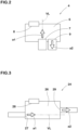
- FIG. 2 is a schematic diagram of the mixing device 4 of the present embodiment in which the bottle container 5 is upright with the mouth portion (5a) facing downward.
- the first inlet 7 of the present embodiment supplies the compressed air to the mixing chamber 6 in a first flow direction (a1).
- the outlet 9 in the present embodiment discharges the mixture in a second flow direction (a2) at a position displaced from a virtual line (VL) extending from the first inlet 7 in the first flow direction (a1).
- the position displaced from the virtual line extending in the first flow direction (a1) means a position that does not overlap with a virtual line extending in the first flow direction (a1) from the center of the first inlet 7.
- the mixing device 4 configured as such efficiently mixes the puncture repair liquid and the compressed air as the puncture repair liquid dripped from the second inlet 8 is stirred in the mixing chamber 6 by the compressed air supplied in the first flow direction (a1). Further, the mixing device 4 in the present embodiment can suppress the flow of agglomerates (aggregates) generated in the mixing chamber 6 into the outlet 9, and thus can suppress narrowing of the flow path caused by the agglomerates accumulating between the bottle unit 2 and the tire T. Therefore, the puncture repair kit 1 including the mixing device 4 can efficiently supply the puncture repair liquid and the compressed air at the same time, and can repair the puncture in a short time.
- the mixture is an aerosol of the puncture repair liquid and the compressed air.
- the puncture repair kit 1 configured as such can efficiently repair punctured areas with a small amount of the puncture repair liquid, and can reduce the effect on sound-absorbing materials, sensors, and the like, even if the tire (T) has the sound-absorbing materials, sensors, and the like inside the tire (T).
- the puncture repair liquid contains at least glycol.
- glycols include ethylene glycol, 1,3-propanediol, propylene glycol, and the like, for example.
- the puncture repair liquid configured as such is suitable for efficiently repairing puncture areas, even when a small amount of the puncture repair liquid is injected as an aerosol into the punctured tire (T).
- the mixing device 4 includes a first member 10 configured to be attached to the mouth portion (5a) of the bottle container 5 and a second member 11 configured to be attached to the first member 10, for example. It is preferred that the first member 10 is screwed onto the mouth portion (5a). The space between the first member 10 and the mouth portion (5a) is sealed by a first sealing member 12, for example.
- the first member 10 configured as such can be easily attached to the bottle container 5 and has excellent airtightness after attachment. It should be noted that the attachment of the first member 10 to the bottle container 5 is not limited to such a manner, and may employ an elastic body to prevent loosening, for example.
- the first member 10 has a breaking portion 13 for breaking a film (not shown) for sealing the mouth portion (5a) of the bottle container 5 in a mint condition.
- the mixing device 4 configured as such can break the sealing of the bottle container 5 when the mixing device 4 is attached to the bottle container 5. Further, since the bottle container 5 is sealed with the film, the puncture repair liquid can be stored for a long period of time without deterioration.
- the first member 10 of the present embodiment has a wall portion 14 provided with the second inlet 8.
- the wall portion 14 is formed as a thin plate, for example.
- the second inlet 8 is at least one through hole provided in the wall portion 14, for example.
- the wall portion 14 is not limited to such a form, and various forms can be adopted as long as the second inlet 8 is provided.
- the position of the wall portion 14 may be changeable, for example, depending on the conditions of use and the like.
- the first member 10 configured as such can change the size of the mixing chamber 6 by changing the position of the wall portion 14, which makes it easy to change the design.
- the second member 11 is screwed to the first member 10.
- the space between the first member 10 and the second member 11 is sealed by a second sealing member 15, for example.
- the mixing chamber 6 consists of a combination of the first member 10 and the second member 11. Therefore, it is preferred that the first member 10 and the second member 11 are assembled in advance before the first member 10 is attached to the bottle container 5. It should be noted that the attachment of the first member 10 and the second member 11 is not limited to such a mode, and a retaining structure and the like by using an elastic body may be adopted, and the first member 10 and the second member 11 may be press-fitted, bonded, or welded together in such a way that they cannot be disassembled, for example.
- the second member 11 of the present embodiment is provided with the first inlet 7 and the outlet 9.
- the first inlet 7 and the outlet 9 are provided in a lower part of the mixing device 4, and the second inlet 8 is provided in an upper part of the mixing device 4 when the bottle container 5 is in the upright state with the mouth portion (5a) facing downward.
- the first inlet 7 is located in the center of the mixing chamber 6 in a plan view, for example. It is preferred that the second inlet 8 and the outlet 9 are located on both sides of the first inlet 7 in the plan view.
- the mixing device 4 configured as such serves for efficient mixing of the puncture repair liquid and the compressed air.
- the first inlet 7 communicates with the mixing chamber 6 by a first opening area S 1, for example.
- the second inlet 8 communicates with the mixing chamber 6 with a second opening area S2, for example. It is preferred that the first opening area S1 is from 1.5 to 15.5 times the second opening area S2. By setting the first opening area S1 to be from 1.5 to 15.5 times the second opening area S2, the ratio of the puncture repair liquid and the compressed air can be maintained within an appropriate range.
- the first opening area S1 is more preferably from 1.5 to 13.0 times the second opening area S2, and even more preferably from 1.5 to 10.0 times the second opening area S2. It is possible that the mixing device 4 configured as such keeps the ratio of the puncture repair liquid and the compressed air in a more appropriate range.
- the second inlet 8 may be multiple through holes provided in the wall portion 14, for example.
- the second opening area S2 is the sum of the opening areas of the holes.
- the shape of the hole(s) of the second inlet 8 is not particularly limited, and can be appropriately selected from circular, elliptical, polygonal, and the like, for example.
- the shapes of the holes of the second inlet 8 may be all the same, or may be different for each hole, for example.
- the first flow direction (a1) and the second flow direction (a2) in the present embodiment are parallel and opposite to each other.
- the mixing device 4 configured as such allows the compressed air to diffuse throughout the mixing chamber 6 and allows the puncture repair liquid and the compressed air to be uniformly mixed.
- FIG. 3 is a schematic view of a mixing device 24 of the second embodiment in the upright state of the bottle container 5 with the mouth portion (5a) facing downwards.
- the mixing device 24 of the second embodiment has a mixing chamber 26, a first inlet 27, a second inlet 28, and an outlet 29.
- the functions and the like of the mixing chamber 26, the first inlet 27, the second inlet 28, and the outlet 29 are the same as those of the mixing chamber 6, the first inlet 7, the second inlet 8, and the outlet 9 described above, and the descriptions thereof are omitted.
- the first flow direction (a1) and the second flow direction (a2) are parallel to each other and have the same orientation. It is possible that the mixing device 24 configured as such smoothly discharges the compressed air while diffusing it in the mixing chamber 26, which is helpful for quick puncture repair.
- the outlet 29 is positioned above the first inlet 27 in the upright state of the bottle container 5 (shown in FIG. 1 ) in which the mouth portion (5a) faces downwards.
- the first inlet 27 and the outlet 29 of the second embodiment are provided in opposite side surfaces of the mixing chamber 26.
- the mixing device 24 configured as such can allow the agglomerates in the puncture repair liquid to deposit in a lower part of the mixing chamber 26, and can more reliably suppress the flow of the agglomerates into the outlet 29.
- the first inlet 27 and the outlet 29 may partially overlap in the vertical direction, for example. Even in this case, the outlet 29 is arranged at a position that does not overlap with the virtual line extending in the first flow direction (a1) from the center of the first inlet 27. In the mixing device 24 configured as such, the height in the vertical direction of the mixing chamber 26 can be reduced, which is helpful for miniaturization.
- FIG. 4 is a schematic diagram of a mixing device 34 of the third embodiment in the upright state of the bottle container 5 with the mouth portion (5a) facing downward.
- the mixing device 24 of the third embodiment has a mixing chamber 36, a first inlet 37, a second inlet 38, and an outlet 39.
- the functions and the like of the mixing chamber 36, the first inlet 37, the second inlet 38, and the outlet 39 are the same as those of the mixing chamber 6, the first inlet 7, the second inlet 8, and the outlet 9 described above, therefore, the descriptions thereof are omitted.
- the first flow direction (a1) and the second flow direction (a2) are parallel and oriented in the same direction like the mixing device 24 of the second embodiment. It is possible that the mixing device 34 configured as such smoothly discharges the mixture while the compressed air diffusing the puncture repair liquid in the mixing chamber 36, which is helpful for quick puncture repair.
- the outlet 39 is positioned above the first inlet 37 in the upright state of the bottle container 5 (shown in FIG. 1 ) with the mouth portion (5a) facing downwards.
- the outlet 39 of the third embodiment is arranged in an upper surface of the mixing chamber 36.
- the mixing device 34 configured as such can allow the agglomerates generated in the mixing chamber 36 to deposit in a lower part of the mixing chamber 36, and thus can more reliably suppress the flow of the agglomerates into the outlet 29.
- FIG. 5 is a schematic diagram of a mixing device 44 of the fourth embodiment in the upright state of the bottle container 5 with the mouth portion (5a) facing downwards.
- the mixing device 44 of the fourth embodiment has a mixing chamber 46, a first inlet 47, a second inlet 48, and an outlet 49.
- the functions and the like of the mixing chamber 46, the first inlet 47, the second inlet 48, and the outlet 49 are the same as those of the mixing chamber 6, the first inlet 7, the second inlet 8, and the outlet 9 described above, and thus the descriptions thereof are omitted.
- the first flow direction (a1) and the second flow direction (a2) are oriented to cross each other.
- the mixing device 44 configured as such can supply the compressed air to circulate within the mixing chamber 46, which helps to efficiently mix the puncture repair liquid and the compressed air.
- the outlet 49 of the fourth embodiment is positioned at approximately the same height as the first inlet 47 in the upright state of the bottle container 5 (shown in FIG. 1 ) with the mouth portion (5a) facing downwards. It is preferred that the mixing chamber 46 of the mixing device 44 before use has an empty space below the first inlet 47 and the outlet 49.
- the mixing device 44 configured as such can allow the aggregates generated in the mixing chamber 46 to deposit in the lower part of the mixing chamber 46 and thus can suppress the aggregates from flowing into the outlet 49.
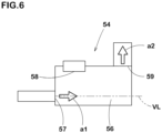
- FIG. 6 is a schematic diagram of a mixing device 54 of the fifth embodiment in the upright state of the bottle container 5 with the mouth portion (5a) facing downwards.
- the mixing device 54 of the fifth embodiment has a mixing chamber 56, a first inlet 57, a second inlet 58, and an outlet 59.
- the functions and the like of the mixing chamber 56, the first inlet 57, the second inlet 58, and the outlet 59 are the same as those of the mixing chamber 6, the first inlet 7, the second inlet 8, and the outlet 9 described above, and thus the descriptions thereof are omitted.
- the first flow direction (a1) and the second flow direction (a2) are oriented to cross each other similar to the mixing device 44 of the fourth embodiment.
- the first flow direction (a1) and the second flow direction (a2) are orthogonal.
- the mixing device 54 configured as such can supply the compressed air to circulate within the mixing chamber 56, which helps to efficiently mix the puncture repair liquid and the compressed air.
- the outlet 59 of the fifth embodiment is formed in an upper surface of the mixing chamber 56 in the upright state of the bottle container 5 (shown in FIG. 1 ) with the mouth portion (5a) facing downwards.
- the mixing device 54 configured as such can allow the aggregates generated in the mixing chamber 56 to deposit in the lower part of the mixing chamber 56 and thus can suppress the aggregates from flowing into the outlet 59.
- the present invention includes the following aspects.
- a mixing device for mixing a puncture repair liquid and compressed air including:
- the mixing device according to any one of Present Inventions 1 to 4, wherein the mixture is an aerosol of the puncture repair liquid and the compressed air.
- the mixing device according to any one of Present Inventions 1 to 4, wherein the puncture repair liquid contains at least glycol.
- a bottle unit including the mixing device according to any one of Present Inventions 1 to 4 and a bottle container, wherein
- a puncture repair kit including the bottle unit according to Present Invention 8 and a compressor for supplying the compressed air.
Landscapes
- Engineering & Computer Science (AREA)
- Mechanical Engineering (AREA)
Abstract
Description
- This application claims the benefit of foreign priority to
Japanese Patent Applications No. JP2022-063545, filed April 6, 2022 - The present invention relates to a mixing device for mixing puncture repair liquid and compressed air, a bottle unit including the mixing device, and a puncture repair kit including the bottle unit.
- Conventionally, puncture repair kits are known for repairing flat tires. For example,
Japanese Unexamined Patent Application No. 2017-056662 - However, since the puncture repair kit of the
Patent Literature 1 injects compressed air after injecting the puncture repair liquid, a large amount of the puncture repair liquid is needed to be injected in order to seal the punctured area with the puncture repair liquid, and the time required for this process is also long. - The present invention was made in view of the above, and a primary object thereof is to provide a mixing device, a bottle unit, and a puncture repair kit for quick puncture repair.
- The present invention is a mixing device for mixing a puncture repair liquid and compressed air including:
- a mixing chamber;
- a first inlet for supplying the compressed air in a first flow direction to the mixing chamber;
- a second inlet for supplying the puncture repair liquid to the mixing chamber; and
- an outlet for discharging a mixture of the puncture repair liquid and the compressed air from the mixing chamber, wherein, the outlet discharges the mixture in a second flow direction at a position displaced from a virtual line extending from the first inlet in the first flow direction.
- It is possible that the mixing device of the present invention repairs punctures in a short period of time by having the configuration described above.
-
-
FIG. 1 is a cross-sectional view conceptually showing a puncture repair kit according to the first embodiment of the present invention. -
FIG. 2 is a schematic diagram of the mixing device of the first embodiment. -
FIG. 3 is a schematic diagram of the mixing device of the second embodiment. -
FIG. 4 is a schematic diagram of the mixing device of the third embodiment. -
FIG. 5 is a schematic diagram of the mixing device of the fourth embodiment. -
FIG. 6 is a schematic diagram of the mixing device of the fifth embodiment. - Embodiments of the present invention will now be described below in conjunction with accompanying drawings.
-
FIG. 1 is a cross-sectional view conceptually showing apuncture repair kit 1 according to the first embodiment. As shown inFIG. 1 ,puncture repair kit 1 is suitably used to supply a puncture repair liquid and compressed air to a punctured tire (T). Thepuncture repair kit 1 of the present embodiment includes abottle unit 2 and acompressor 3 for supplying compressed air. - The
bottle unit 2 of the present embodiment includes amixing device 4 and abottle container 5 containing a puncture repair liquid. Thebottle container 5 has a mouth portion (5a) for receiving the puncture repair liquid into thebottle container 5, for example. It is preferred that themixing device 4 is attached to the mouth portion (5a).FIG. 1 shows an upright state of thebottle container 5 with the mouth portion (5a) facing downwards. - The
mixing device 4 is suitably used for mixing the puncture repair liquid and the compressed air. Themixing device 4 of the present embodiment has amixing chamber 6, afirst inlet 7 for supplying the compressed air to themixing chamber 6, asecond inlet 8 for supplying the puncture repair liquid to themixing chamber 6, anoutlet 9 for discharging a mixture of the puncture repair liquid and the compressed air from themixing chamber 6. Themixing device 4 configured as such can drip the puncture repair liquid into themixing chamber 6 as themixing chamber 6 is repeatedly brought into positive and negative pressure states by the pulsation of the compressed air supplied from thecompressor 3. -
FIG. 2 is a schematic diagram of themixing device 4 of the present embodiment in which thebottle container 5 is upright with the mouth portion (5a) facing downward. As shown inFIGs. 1 and2 , thefirst inlet 7 of the present embodiment supplies the compressed air to themixing chamber 6 in a first flow direction (a1). Theoutlet 9 in the present embodiment discharges the mixture in a second flow direction (a2) at a position displaced from a virtual line (VL) extending from thefirst inlet 7 in the first flow direction (a1). Here, the position displaced from the virtual line extending in the first flow direction (a1) means a position that does not overlap with a virtual line extending in the first flow direction (a1) from the center of thefirst inlet 7. - It is possible that the
mixing device 4 configured as such efficiently mixes the puncture repair liquid and the compressed air as the puncture repair liquid dripped from thesecond inlet 8 is stirred in themixing chamber 6 by the compressed air supplied in the first flow direction (a1). Further, themixing device 4 in the present embodiment can suppress the flow of agglomerates (aggregates) generated in themixing chamber 6 into theoutlet 9, and thus can suppress narrowing of the flow path caused by the agglomerates accumulating between thebottle unit 2 and the tire T. Therefore, thepuncture repair kit 1 including themixing device 4 can efficiently supply the puncture repair liquid and the compressed air at the same time, and can repair the puncture in a short time. - In a more preferred form, the mixture is an aerosol of the puncture repair liquid and the compressed air. The
puncture repair kit 1 configured as such can efficiently repair punctured areas with a small amount of the puncture repair liquid, and can reduce the effect on sound-absorbing materials, sensors, and the like, even if the tire (T) has the sound-absorbing materials, sensors, and the like inside the tire (T). - It is preferred that the puncture repair liquid contains at least glycol. Examples of glycols include ethylene glycol, 1,3-propanediol, propylene glycol, and the like, for example. The puncture repair liquid configured as such is suitable for efficiently repairing puncture areas, even when a small amount of the puncture repair liquid is injected as an aerosol into the punctured tire (T).
- As shown in
FIG. 1 , themixing device 4 includes afirst member 10 configured to be attached to the mouth portion (5a) of thebottle container 5 and asecond member 11 configured to be attached to thefirst member 10, for example. It is preferred that thefirst member 10 is screwed onto the mouth portion (5a). The space between thefirst member 10 and the mouth portion (5a) is sealed by a first sealingmember 12, for example. Thefirst member 10 configured as such can be easily attached to thebottle container 5 and has excellent airtightness after attachment. It should be noted that the attachment of thefirst member 10 to thebottle container 5 is not limited to such a manner, and may employ an elastic body to prevent loosening, for example. - It is preferred that the
first member 10 has a breakingportion 13 for breaking a film (not shown) for sealing the mouth portion (5a) of thebottle container 5 in a mint condition. Themixing device 4 configured as such can break the sealing of thebottle container 5 when themixing device 4 is attached to thebottle container 5. Further, since thebottle container 5 is sealed with the film, the puncture repair liquid can be stored for a long period of time without deterioration. - The
first member 10 of the present embodiment has awall portion 14 provided with thesecond inlet 8. Thewall portion 14 is formed as a thin plate, for example. Thesecond inlet 8 is at least one through hole provided in thewall portion 14, for example. Thewall portion 14 is not limited to such a form, and various forms can be adopted as long as thesecond inlet 8 is provided. The position of thewall portion 14 may be changeable, for example, depending on the conditions of use and the like. Thefirst member 10 configured as such can change the size of themixing chamber 6 by changing the position of thewall portion 14, which makes it easy to change the design. - It is preferred that the
second member 11 is screwed to thefirst member 10. The space between thefirst member 10 and thesecond member 11 is sealed by a second sealingmember 15, for example. Themixing chamber 6 consists of a combination of thefirst member 10 and thesecond member 11. Therefore, it is preferred that thefirst member 10 and thesecond member 11 are assembled in advance before thefirst member 10 is attached to thebottle container 5. It should be noted that the attachment of thefirst member 10 and thesecond member 11 is not limited to such a mode, and a retaining structure and the like by using an elastic body may be adopted, and thefirst member 10 and thesecond member 11 may be press-fitted, bonded, or welded together in such a way that they cannot be disassembled, for example. - The
second member 11 of the present embodiment is provided with thefirst inlet 7 and theoutlet 9. In themixing device 4 of the present embodiment, thefirst inlet 7 and theoutlet 9 are provided in a lower part of themixing device 4, and thesecond inlet 8 is provided in an upper part of themixing device 4 when thebottle container 5 is in the upright state with the mouth portion (5a) facing downward. Thefirst inlet 7 is located in the center of the mixingchamber 6 in a plan view, for example. It is preferred that thesecond inlet 8 and theoutlet 9 are located on both sides of thefirst inlet 7 in the plan view. Themixing device 4 configured as such serves for efficient mixing of the puncture repair liquid and the compressed air. - The
first inlet 7 communicates with the mixingchamber 6 by a firstopening area S 1, for example. Thesecond inlet 8 communicates with the mixingchamber 6 with a second opening area S2, for example. It is preferred that the first opening area S1 is from 1.5 to 15.5 times the second opening area S2. By setting the first opening area S1 to be from 1.5 to 15.5 times the second opening area S2, the ratio of the puncture repair liquid and the compressed air can be maintained within an appropriate range. - From this point of view, the first opening area S1 is more preferably from 1.5 to 13.0 times the second opening area S2, and even more preferably from 1.5 to 10.0 times the second opening area S2. It is possible that the
mixing device 4 configured as such keeps the ratio of the puncture repair liquid and the compressed air in a more appropriate range. - It should be noted that the
second inlet 8 may be multiple through holes provided in thewall portion 14, for example. In the present embodiment, when thesecond inlet 8 is a plurality of holes, the second opening area S2 is the sum of the opening areas of the holes. - The shape of the hole(s) of the
second inlet 8 is not particularly limited, and can be appropriately selected from circular, elliptical, polygonal, and the like, for example. When thesecond inlet 8 is a plurality of holes, the shapes of the holes of thesecond inlet 8 may be all the same, or may be different for each hole, for example. - The first flow direction (a1) and the second flow direction (a2) in the present embodiment are parallel and opposite to each other. The
mixing device 4 configured as such allows the compressed air to diffuse throughout the mixingchamber 6 and allows the puncture repair liquid and the compressed air to be uniformly mixed. -
FIG. 3 is a schematic view of amixing device 24 of the second embodiment in the upright state of thebottle container 5 with the mouth portion (5a) facing downwards. As shown inFIG. 3 , the mixingdevice 24 of the second embodiment has a mixingchamber 26, afirst inlet 27, asecond inlet 28, and anoutlet 29. The functions and the like of the mixingchamber 26, thefirst inlet 27, thesecond inlet 28, and theoutlet 29 are the same as those of the mixingchamber 6, thefirst inlet 7, thesecond inlet 8, and theoutlet 9 described above, and the descriptions thereof are omitted. - In the
mixing device 24 of the second embodiment, the first flow direction (a1) and the second flow direction (a2) are parallel to each other and have the same orientation. It is possible that the mixingdevice 24 configured as such smoothly discharges the compressed air while diffusing it in the mixingchamber 26, which is helpful for quick puncture repair. - It is preferred that the
outlet 29 is positioned above thefirst inlet 27 in the upright state of the bottle container 5 (shown inFIG. 1 ) in which the mouth portion (5a) faces downwards. Thefirst inlet 27 and theoutlet 29 of the second embodiment are provided in opposite side surfaces of the mixingchamber 26. The mixingdevice 24 configured as such can allow the agglomerates in the puncture repair liquid to deposit in a lower part of the mixingchamber 26, and can more reliably suppress the flow of the agglomerates into theoutlet 29. - The
first inlet 27 and theoutlet 29 may partially overlap in the vertical direction, for example. Even in this case, theoutlet 29 is arranged at a position that does not overlap with the virtual line extending in the first flow direction (a1) from the center of thefirst inlet 27. In themixing device 24 configured as such, the height in the vertical direction of the mixingchamber 26 can be reduced, which is helpful for miniaturization. -
FIG. 4 is a schematic diagram of amixing device 34 of the third embodiment in the upright state of thebottle container 5 with the mouth portion (5a) facing downward. As shown inFIG. 4 , the mixingdevice 24 of the third embodiment has a mixingchamber 36, afirst inlet 37, asecond inlet 38, and anoutlet 39. The functions and the like of the mixingchamber 36, thefirst inlet 37, thesecond inlet 38, and theoutlet 39 are the same as those of the mixingchamber 6, thefirst inlet 7, thesecond inlet 8, and theoutlet 9 described above, therefore, the descriptions thereof are omitted. - In the
mixing device 34 of the third embodiment, the first flow direction (a1) and the second flow direction (a2) are parallel and oriented in the same direction like themixing device 24 of the second embodiment. It is possible that the mixingdevice 34 configured as such smoothly discharges the mixture while the compressed air diffusing the puncture repair liquid in the mixingchamber 36, which is helpful for quick puncture repair. - It is preferred that the
outlet 39 is positioned above thefirst inlet 37 in the upright state of the bottle container 5 (shown inFIG. 1 ) with the mouth portion (5a) facing downwards. Theoutlet 39 of the third embodiment is arranged in an upper surface of the mixingchamber 36. The mixingdevice 34 configured as such can allow the agglomerates generated in the mixingchamber 36 to deposit in a lower part of the mixingchamber 36, and thus can more reliably suppress the flow of the agglomerates into theoutlet 29. -
FIG. 5 is a schematic diagram of amixing device 44 of the fourth embodiment in the upright state of thebottle container 5 with the mouth portion (5a) facing downwards. As shown inFIG. 5 , the mixingdevice 44 of the fourth embodiment has a mixingchamber 46, afirst inlet 47, asecond inlet 48, and anoutlet 49. The functions and the like of the mixingchamber 46, thefirst inlet 47, thesecond inlet 48, and theoutlet 49 are the same as those of the mixingchamber 6, thefirst inlet 7, thesecond inlet 8, and theoutlet 9 described above, and thus the descriptions thereof are omitted. - In the
mixing device 44 of the fourth embodiment, the first flow direction (a1) and the second flow direction (a2) are oriented to cross each other. The mixingdevice 44 configured as such can supply the compressed air to circulate within the mixingchamber 46, which helps to efficiently mix the puncture repair liquid and the compressed air. - The
outlet 49 of the fourth embodiment is positioned at approximately the same height as thefirst inlet 47 in the upright state of the bottle container 5 (shown inFIG. 1 ) with the mouth portion (5a) facing downwards. It is preferred that the mixingchamber 46 of the mixingdevice 44 before use has an empty space below thefirst inlet 47 and theoutlet 49. The mixingdevice 44 configured as such can allow the aggregates generated in the mixingchamber 46 to deposit in the lower part of the mixingchamber 46 and thus can suppress the aggregates from flowing into theoutlet 49. -
FIG. 6 is a schematic diagram of amixing device 54 of the fifth embodiment in the upright state of thebottle container 5 with the mouth portion (5a) facing downwards. As shown inFIG. 6 , the mixingdevice 54 of the fifth embodiment has a mixingchamber 56, afirst inlet 57, asecond inlet 58, and anoutlet 59. The functions and the like of the mixingchamber 56, thefirst inlet 57, thesecond inlet 58, and theoutlet 59 are the same as those of the mixingchamber 6, thefirst inlet 7, thesecond inlet 8, and theoutlet 9 described above, and thus the descriptions thereof are omitted. - In the
mixing device 54 of the fifth embodiment, the first flow direction (a1) and the second flow direction (a2) are oriented to cross each other similar to themixing device 44 of the fourth embodiment. In themixing device 54 of the fifth embodiment, the first flow direction (a1) and the second flow direction (a2) are orthogonal. The mixingdevice 54 configured as such can supply the compressed air to circulate within the mixingchamber 56, which helps to efficiently mix the puncture repair liquid and the compressed air. - The
outlet 59 of the fifth embodiment is formed in an upper surface of the mixingchamber 56 in the upright state of the bottle container 5 (shown inFIG. 1 ) with the mouth portion (5a) facing downwards. The mixingdevice 54 configured as such can allow the aggregates generated in the mixingchamber 56 to deposit in the lower part of the mixingchamber 56 and thus can suppress the aggregates from flowing into theoutlet 59. - While detailed description has been made of especially preferred embodiments of the present invention, the present invention can be embodied in various forms without being limited to the illustrated embodiments.
- The present invention includes the following aspects.
- A mixing device for mixing a puncture repair liquid and compressed air including:
- a mixing chamber;
- a first inlet for supplying the compressed air in a first flow direction to the mixing chamber;
- a second inlet for supplying the puncture repair liquid to the mixing chamber; and
- an outlet for discharging a mixture of the puncture repair liquid and the compressed air from the mixing chamber, wherein, the outlet discharges the mixture in a second flow direction at a position displaced from a virtual line extending from the first inlet in the first flow direction.
- The mixing device according to
Present Invention 1, wherein the first flow direction and the second flow direction are parallel and opposite to each other. - The mixing device according to
Present Invention 1, wherein the first flow direction and the second flow direction are parallel to each other and have the same orientation. - The mixing device according to
Present Invention 1, wherein the first flow direction and the second flow direction are oriented to cross each other. - The mixing device according to any one of
Present Inventions 1 to 4, wherein the mixture is an aerosol of the puncture repair liquid and the compressed air. - The mixing device according to any one of
Present Inventions 1 to 4, wherein the puncture repair liquid contains at least glycol. - The mixing device according to any one of
Present Inventions 1 to 4, wherein - the first inlet communicates with the mixing chamber by a first opening area,
- the second inlet communicates with the mixing chamber by a second opening area, and
- the first opening area is from 1.5 to 15.5 times the second opening area.
- A bottle unit including the mixing device according to any one of
Present Inventions 1 to 4 and a bottle container, wherein - the bottle container contains the puncture repair liquid and has a mouth portion for receiving the puncture repair liquid, and
- the mixing device is attached to the mouth portion.
- The bottle unit according to
Present Invention 8, wherein the outlet is positioned above the first inlet in an upright state of the bottle container with the mouth portion facing downwards. - A puncture repair kit including the bottle unit according to
Present Invention 8 and a compressor for supplying the compressed air. -
- 4, 24, 34, 44, 54
- mixing device
- 6, 26, 36, 46, 56
- mixing chamber
- 7, 27, 37, 47, 57
- first inlet
- 8, 28, 38, 48, 58
- second inlet
- 9, 29, 39, 49, 59
- outlet
Claims (10)
- A mixing device for mixing a puncture repair liquid and compressed air comprising:a mixing chamber;a first inlet for supplying the compressed air in a first flow direction to the mixing chamber;a second inlet for supplying the puncture repair liquid to the mixing chamber; andan outlet for discharging a mixture of the puncture repair liquid and the compressed air from the mixing chamber, wherein, the outlet discharges the mixture in a second flow direction at a position displaced from a virtual line extending from the first inlet in the first flow direction.
- The mixing device according to claim 1, wherein the first flow direction and the second flow direction are parallel and opposite to each other.
- The mixing device according to claim 1, wherein the first flow direction and the second flow direction are parallel to each other and have the same orientation.
- The mixing device according to claim 1, wherein the first flow direction and the second flow direction are oriented to cross each other.
- The mixing device according to any one of claims 1 to 4, wherein the mixture is an aerosol of the puncture repair liquid and the compressed air.
- The mixing device according to any one of claims 1 to 4, wherein the puncture repair liquid contains at least glycol.
- The mixing device according to any one of claims 1 to 4, whereinthe first inlet communicates with the mixing chamber by a first opening area,the second inlet communicates with the mixing chamber by a second opening area, andthe first opening area is from 1.5 to 15.5 times the second opening area.
- A bottle unit comprising the mixing device according to any one of claims 1 to 4 and a bottle container, whereinthe bottle container contains the puncture repair liquid and has a mouth portion for receiving the puncture repair liquid, andthe mixing device is attached to the mouth portion.
- The bottle unit according to claim 8, wherein the outlet is positioned above the first inlet in an upright state of the bottle container with the mouth portion facing downwards.
- A puncture repair kit comprising the bottle unit according to claim 8 and a compressor for supplying the compressed air.
Applications Claiming Priority (1)
| Application Number | Priority Date | Filing Date | Title |
|---|---|---|---|
| JP2022063545A JP2023154297A (en) | 2022-04-06 | 2022-04-06 | Mixing equipment, bottle units and puncture repair kits |
Publications (1)
| Publication Number | Publication Date |
|---|---|
| EP4257346A1 true EP4257346A1 (en) | 2023-10-11 |
Family
ID=85225228
Family Applications (1)
| Application Number | Title | Priority Date | Filing Date |
|---|---|---|---|
| EP23155938.6A Pending EP4257346A1 (en) | 2022-04-06 | 2023-02-10 | Mixing device, bottle unit, and puncture repair kit |
Country Status (4)
| Country | Link |
|---|---|
| US (1) | US12365154B2 (en) |
| EP (1) | EP4257346A1 (en) |
| JP (1) | JP2023154297A (en) |
| CN (1) | CN116890469A (en) |
Cited By (1)
| Publication number | Priority date | Publication date | Assignee | Title |
|---|---|---|---|---|
| EP4438279A1 (en) * | 2023-03-27 | 2024-10-02 | Sumitomo Rubber Industries, Ltd. | Bottle set and puncture repair kit |
Families Citing this family (1)
| Publication number | Priority date | Publication date | Assignee | Title |
|---|---|---|---|---|
| JP7852360B2 (en) * | 2022-04-06 | 2026-04-28 | 住友ゴム工業株式会社 | Mixing device, bottle unit, and tire repair kit |
Citations (11)
| Publication number | Priority date | Publication date | Assignee | Title |
|---|---|---|---|---|
| US20030056851A1 (en) * | 2001-02-16 | 2003-03-27 | Eriksen Steen Mandsfelt | Device for sealing and inflating an inflatable object |
| US20040159365A1 (en) * | 2002-10-31 | 2004-08-19 | David Cowan | Apparatus for sealing, inflating, and repairing tires |
| EP2305570A1 (en) * | 2008-06-19 | 2011-04-06 | Bridgestone Corporation | Structure for preventing dislocation of container, and sealing pump-up device |
| GB2482016A (en) * | 2010-07-16 | 2012-01-18 | David Leslie White | Device for dispensing liquids |
| US8453683B2 (en) * | 2007-06-18 | 2013-06-04 | Bridgestone Corporation | Sealing and pump-up device |
| US8631840B2 (en) * | 2010-04-07 | 2014-01-21 | Tek Global S.R.L. | Kit for repairing and inflating inflatable items |
| JP2017056662A (en) | 2015-09-17 | 2017-03-23 | 住友ゴム工業株式会社 | Puncture repair kit |
| DE102018219042A1 (en) * | 2018-11-08 | 2020-05-14 | Continental Reifen Deutschland Gmbh | Distribution device for producing and transporting a dispersion comprising both a gas and a sealant, system for sealing and inflating pneumatic tires, a method for at least partially sealing a leak in a pneumatic tire and a corresponding use |
| DE102019217781A1 (en) * | 2019-05-28 | 2020-12-03 | Continental Reifen Deutschland Gmbh | Device for transporting compressed air and / or sealant into a pneumatic vehicle tire, portable / transportable system comprising the device and a method for sealing and inflating pneumatic vehicle tires and the use of a locking unit |
| WO2021099028A1 (en) * | 2019-11-19 | 2021-05-27 | Continental Reifen Deutschland Gmbh | Apparatus for transporting compressed air and/or sealant in a vehicle tire and portable/transportable system for sealing and inflating vehicle tires |
| US20220024163A1 (en) * | 2018-11-08 | 2022-01-27 | Continental Reifen Deutschland Gmbh | Distributor device, system, and method for sealing and using a metering unit |
Family Cites Families (11)
| Publication number | Priority date | Publication date | Assignee | Title |
|---|---|---|---|---|
| ITTO20040121A1 (en) * | 2004-02-27 | 2004-05-27 | Tek Srl | CONTAINER FOR A SEALANT LIQUID FOR THE REPAIR OF INFLATABLE OBJECTS, IN PARTICULAR PNEMATICI, AND REPAIR KIT PROVIDED WITH SUCH CONTAINER |
| JP4133945B2 (en) * | 2004-06-28 | 2008-08-13 | 住友ゴム工業株式会社 | Tire puncture sealant supply and extraction device |
| JP4666613B2 (en) * | 2004-08-30 | 2011-04-06 | 株式会社ブリヂストン | Sealant injection device |
| US20080145245A1 (en) * | 2004-12-22 | 2008-06-19 | Wen-San Chou | Compressor for tire inflating combination |
| JP4519065B2 (en) * | 2005-11-29 | 2010-08-04 | 株式会社ブリヂストン | Tire sealing and pump-up equipment |
| JP4777832B2 (en) * | 2006-06-20 | 2011-09-21 | 株式会社ブリヂストン | Sealing / pump-up device |
| US20080230142A1 (en) * | 2007-03-19 | 2008-09-25 | Scott Noble Hickman | Tire sealant and air dispenser apparatus with a sealing mechanism |
| JP4766093B2 (en) * | 2008-09-22 | 2011-09-07 | 横浜ゴム株式会社 | Puncture repair liquid container |
| RU2519397C2 (en) * | 2009-01-07 | 2014-06-10 | Тридел Рисерч Пти. Лтд. | Device for repair and inflation of damaged inflatable articles |
| US8746293B2 (en) * | 2011-10-12 | 2014-06-10 | Wen San Chou | Device for sealing and inflating inflatable object |
| JP7852360B2 (en) * | 2022-04-06 | 2026-04-28 | 住友ゴム工業株式会社 | Mixing device, bottle unit, and tire repair kit |
-
2022
- 2022-04-06 JP JP2022063545A patent/JP2023154297A/en active Pending
-
2023
- 2023-02-10 EP EP23155938.6A patent/EP4257346A1/en active Pending
- 2023-02-21 CN CN202310142204.8A patent/CN116890469A/en active Pending
- 2023-03-16 US US18/122,567 patent/US12365154B2/en active Active
Patent Citations (11)
| Publication number | Priority date | Publication date | Assignee | Title |
|---|---|---|---|---|
| US20030056851A1 (en) * | 2001-02-16 | 2003-03-27 | Eriksen Steen Mandsfelt | Device for sealing and inflating an inflatable object |
| US20040159365A1 (en) * | 2002-10-31 | 2004-08-19 | David Cowan | Apparatus for sealing, inflating, and repairing tires |
| US8453683B2 (en) * | 2007-06-18 | 2013-06-04 | Bridgestone Corporation | Sealing and pump-up device |
| EP2305570A1 (en) * | 2008-06-19 | 2011-04-06 | Bridgestone Corporation | Structure for preventing dislocation of container, and sealing pump-up device |
| US8631840B2 (en) * | 2010-04-07 | 2014-01-21 | Tek Global S.R.L. | Kit for repairing and inflating inflatable items |
| GB2482016A (en) * | 2010-07-16 | 2012-01-18 | David Leslie White | Device for dispensing liquids |
| JP2017056662A (en) | 2015-09-17 | 2017-03-23 | 住友ゴム工業株式会社 | Puncture repair kit |
| DE102018219042A1 (en) * | 2018-11-08 | 2020-05-14 | Continental Reifen Deutschland Gmbh | Distribution device for producing and transporting a dispersion comprising both a gas and a sealant, system for sealing and inflating pneumatic tires, a method for at least partially sealing a leak in a pneumatic tire and a corresponding use |
| US20220024163A1 (en) * | 2018-11-08 | 2022-01-27 | Continental Reifen Deutschland Gmbh | Distributor device, system, and method for sealing and using a metering unit |
| DE102019217781A1 (en) * | 2019-05-28 | 2020-12-03 | Continental Reifen Deutschland Gmbh | Device for transporting compressed air and / or sealant into a pneumatic vehicle tire, portable / transportable system comprising the device and a method for sealing and inflating pneumatic vehicle tires and the use of a locking unit |
| WO2021099028A1 (en) * | 2019-11-19 | 2021-05-27 | Continental Reifen Deutschland Gmbh | Apparatus for transporting compressed air and/or sealant in a vehicle tire and portable/transportable system for sealing and inflating vehicle tires |
Cited By (1)
| Publication number | Priority date | Publication date | Assignee | Title |
|---|---|---|---|---|
| EP4438279A1 (en) * | 2023-03-27 | 2024-10-02 | Sumitomo Rubber Industries, Ltd. | Bottle set and puncture repair kit |
Also Published As
| Publication number | Publication date |
|---|---|
| JP2023154297A (en) | 2023-10-19 |
| US20230321932A1 (en) | 2023-10-12 |
| US12365154B2 (en) | 2025-07-22 |
| CN116890469A (en) | 2023-10-17 |
Similar Documents
| Publication | Publication Date | Title |
|---|---|---|
| US12070916B2 (en) | Mixing device, bottle unit, and puncture repair kit | |
| US12365154B2 (en) | Mixing device, bottle unit, and puncture repair kit | |
| US8016002B2 (en) | Sealing/pump-up device | |
| CN101683767B (en) | Tire sealant liquid container | |
| US20120219468A1 (en) | Droplet discharging device | |
| US8210397B2 (en) | Dispensing device having mixing function | |
| JP2010070251A (en) | Tire sealant liquid container | |
| US12496788B2 (en) | Sealant bottle | |
| US10946350B2 (en) | Mixing device for mixing a liquid plastics component with a gas | |
| JP5357813B2 (en) | Cap unit | |
| JP5364136B2 (en) | Punk repair kit | |
| JP5357703B2 (en) | Punk repair kit | |
| EP4438279B1 (en) | Bottle set and puncture repair kit | |
| US20260070290A1 (en) | Puncture repair kit | |
| EP4520513A1 (en) | Mixing device, mixing method, bottle unit, and puncture repair kit | |
| EP4360859A1 (en) | Bottle unit and puncture repair kit | |
| JP2025052703A (en) | Mixing device, bottle unit and puncture repair kit | |
| JP2011046112A (en) | Sealing pump-up device | |
| JP2025052702A (en) | Mixing device, bottle unit and puncture repair kit | |
| KR101901759B1 (en) | an elastic ample adapter for portable mist spray | |
| KR20250116026A (en) | Sealant Bottles and Tire Repair Methods | |
| JP2024139380A (en) | Mixing device, bottle unit and puncture repair kit | |
| WO2025069145A1 (en) | Puncture repair kit, mixing device, puncture repair method, and mixing method | |
| CN122058564A (en) | Perforation repair kit | |
| WO2024194982A1 (en) | Liquid dispensing container |
Legal Events
| Date | Code | Title | Description |
|---|---|---|---|
| PUAI | Public reference made under article 153(3) epc to a published international application that has entered the european phase |
Free format text: ORIGINAL CODE: 0009012 |
|
| STAA | Information on the status of an ep patent application or granted ep patent |
Free format text: STATUS: THE APPLICATION HAS BEEN PUBLISHED |
|
| AK | Designated contracting states |
Kind code of ref document: A1 Designated state(s): AL AT BE BG CH CY CZ DE DK EE ES FI FR GB GR HR HU IE IS IT LI LT LU LV MC ME MK MT NL NO PL PT RO RS SE SI SK SM TR |
|
| STAA | Information on the status of an ep patent application or granted ep patent |
Free format text: STATUS: REQUEST FOR EXAMINATION WAS MADE |
|
| 17P | Request for examination filed |
Effective date: 20240320 |
|
| RBV | Designated contracting states (corrected) |
Designated state(s): AL AT BE BG CH CY CZ DE DK EE ES FI FR GB GR HR HU IE IS IT LI LT LU LV MC ME MK MT NL NO PL PT RO RS SE SI SK SM TR |
|
| P01 | Opt-out of the competence of the unified patent court (upc) registered |
Effective date: 20240327 |