EP4257342A1 - A toilet seat connection tool and a toilet seat applying same - Google Patents
A toilet seat connection tool and a toilet seat applying same Download PDFInfo
- Publication number
- EP4257342A1 EP4257342A1 EP22187485.2A EP22187485A EP4257342A1 EP 4257342 A1 EP4257342 A1 EP 4257342A1 EP 22187485 A EP22187485 A EP 22187485A EP 4257342 A1 EP4257342 A1 EP 4257342A1
- Authority
- EP
- European Patent Office
- Prior art keywords
- toilet seat
- profiling groove
- base plate
- worktable
- connection tool
- Prior art date
- Legal status (The legal status is an assumption and is not a legal conclusion. Google has not performed a legal analysis and makes no representation as to the accuracy of the status listed.)
- Granted
Links
Images


Classifications
-
- B—PERFORMING OPERATIONS; TRANSPORTING
- B29—WORKING OF PLASTICS; WORKING OF SUBSTANCES IN A PLASTIC STATE IN GENERAL
- B29C—SHAPING OR JOINING OF PLASTICS; SHAPING OF MATERIAL IN A PLASTIC STATE, NOT OTHERWISE PROVIDED FOR; AFTER-TREATMENT OF THE SHAPED PRODUCTS, e.g. REPAIRING
- B29C65/00—Joining or sealing of preformed parts, e.g. welding of plastics materials; Apparatus therefor
- B29C65/02—Joining or sealing of preformed parts, e.g. welding of plastics materials; Apparatus therefor by heating, with or without pressure
- B29C65/06—Joining or sealing of preformed parts, e.g. welding of plastics materials; Apparatus therefor by heating, with or without pressure using friction, e.g. spin welding
- B29C65/069—Joining or sealing of preformed parts, e.g. welding of plastics materials; Apparatus therefor by heating, with or without pressure using friction, e.g. spin welding the welding tool cooperating with specially formed features of at least one of the parts to be joined, e.g. cooperating with holes or ribs of at least one of the parts to be joined
-
- A—HUMAN NECESSITIES
- A47—FURNITURE; DOMESTIC ARTICLES OR APPLIANCES; COFFEE MILLS; SPICE MILLS; SUCTION CLEANERS IN GENERAL
- A47K—SANITARY EQUIPMENT; ACCESSORIES THEREFOR, e.g. TOILET ACCESSORIES
- A47K13/00—Seats or covers for all kinds of closets
- A47K13/02—Seats or covers for all kinds of closets of plastic materials
-
- B—PERFORMING OPERATIONS; TRANSPORTING
- B29—WORKING OF PLASTICS; WORKING OF SUBSTANCES IN A PLASTIC STATE IN GENERAL
- B29C—SHAPING OR JOINING OF PLASTICS; SHAPING OF MATERIAL IN A PLASTIC STATE, NOT OTHERWISE PROVIDED FOR; AFTER-TREATMENT OF THE SHAPED PRODUCTS, e.g. REPAIRING
- B29C65/00—Joining or sealing of preformed parts, e.g. welding of plastics materials; Apparatus therefor
- B29C65/78—Means for handling the parts to be joined, e.g. for making containers or hollow articles, e.g. means for handling sheets, plates, web-like materials, tubular articles, hollow articles or elements to be joined therewith; Means for discharging the joined articles from the joining apparatus
- B29C65/7802—Positioning the parts to be joined, e.g. aligning, indexing or centring
- B29C65/7805—Positioning the parts to be joined, e.g. aligning, indexing or centring the parts to be joined comprising positioning features
- B29C65/7814—Positioning the parts to be joined, e.g. aligning, indexing or centring the parts to be joined comprising positioning features in the form of inter-cooperating positioning features, e.g. tenons and mortises
-
- B—PERFORMING OPERATIONS; TRANSPORTING
- B29—WORKING OF PLASTICS; WORKING OF SUBSTANCES IN A PLASTIC STATE IN GENERAL
- B29C—SHAPING OR JOINING OF PLASTICS; SHAPING OF MATERIAL IN A PLASTIC STATE, NOT OTHERWISE PROVIDED FOR; AFTER-TREATMENT OF THE SHAPED PRODUCTS, e.g. REPAIRING
- B29C65/00—Joining or sealing of preformed parts, e.g. welding of plastics materials; Apparatus therefor
- B29C65/78—Means for handling the parts to be joined, e.g. for making containers or hollow articles, e.g. means for handling sheets, plates, web-like materials, tubular articles, hollow articles or elements to be joined therewith; Means for discharging the joined articles from the joining apparatus
- B29C65/7841—Holding or clamping means for handling purposes
- B29C65/7847—Holding or clamping means for handling purposes using vacuum to hold at least one of the parts to be joined
-
- B—PERFORMING OPERATIONS; TRANSPORTING
- B29—WORKING OF PLASTICS; WORKING OF SUBSTANCES IN A PLASTIC STATE IN GENERAL
- B29C—SHAPING OR JOINING OF PLASTICS; SHAPING OF MATERIAL IN A PLASTIC STATE, NOT OTHERWISE PROVIDED FOR; AFTER-TREATMENT OF THE SHAPED PRODUCTS, e.g. REPAIRING
- B29C66/00—General aspects of processes or apparatus for joining preformed parts
- B29C66/01—General aspects dealing with the joint area or with the area to be joined
- B29C66/05—Particular design of joint configurations
- B29C66/10—Particular design of joint configurations particular design of the joint cross-sections
- B29C66/11—Joint cross-sections comprising a single joint-segment, i.e. one of the parts to be joined comprising a single joint-segment in the joint cross-section
- B29C66/112—Single lapped joints
-
- B—PERFORMING OPERATIONS; TRANSPORTING
- B29—WORKING OF PLASTICS; WORKING OF SUBSTANCES IN A PLASTIC STATE IN GENERAL
- B29C—SHAPING OR JOINING OF PLASTICS; SHAPING OF MATERIAL IN A PLASTIC STATE, NOT OTHERWISE PROVIDED FOR; AFTER-TREATMENT OF THE SHAPED PRODUCTS, e.g. REPAIRING
- B29C66/00—General aspects of processes or apparatus for joining preformed parts
- B29C66/01—General aspects dealing with the joint area or with the area to be joined
- B29C66/05—Particular design of joint configurations
- B29C66/10—Particular design of joint configurations particular design of the joint cross-sections
- B29C66/11—Joint cross-sections comprising a single joint-segment, i.e. one of the parts to be joined comprising a single joint-segment in the joint cross-section
- B29C66/114—Single butt joints
-
- B—PERFORMING OPERATIONS; TRANSPORTING
- B29—WORKING OF PLASTICS; WORKING OF SUBSTANCES IN A PLASTIC STATE IN GENERAL
- B29C—SHAPING OR JOINING OF PLASTICS; SHAPING OF MATERIAL IN A PLASTIC STATE, NOT OTHERWISE PROVIDED FOR; AFTER-TREATMENT OF THE SHAPED PRODUCTS, e.g. REPAIRING
- B29C66/00—General aspects of processes or apparatus for joining preformed parts
- B29C66/01—General aspects dealing with the joint area or with the area to be joined
- B29C66/05—Particular design of joint configurations
- B29C66/10—Particular design of joint configurations particular design of the joint cross-sections
- B29C66/13—Single flanged joints; Fin-type joints; Single hem joints; Edge joints; Interpenetrating fingered joints; Other specific particular designs of joint cross-sections not provided for in groups B29C66/11 - B29C66/12
- B29C66/131—Single flanged joints, i.e. one of the parts to be joined being rigid and flanged in the joint area
-
- B—PERFORMING OPERATIONS; TRANSPORTING
- B29—WORKING OF PLASTICS; WORKING OF SUBSTANCES IN A PLASTIC STATE IN GENERAL
- B29C—SHAPING OR JOINING OF PLASTICS; SHAPING OF MATERIAL IN A PLASTIC STATE, NOT OTHERWISE PROVIDED FOR; AFTER-TREATMENT OF THE SHAPED PRODUCTS, e.g. REPAIRING
- B29C66/00—General aspects of processes or apparatus for joining preformed parts
- B29C66/01—General aspects dealing with the joint area or with the area to be joined
- B29C66/05—Particular design of joint configurations
- B29C66/301—Three-dimensional joints, i.e. the joined area being substantially non-flat
-
- B—PERFORMING OPERATIONS; TRANSPORTING
- B29—WORKING OF PLASTICS; WORKING OF SUBSTANCES IN A PLASTIC STATE IN GENERAL
- B29C—SHAPING OR JOINING OF PLASTICS; SHAPING OF MATERIAL IN A PLASTIC STATE, NOT OTHERWISE PROVIDED FOR; AFTER-TREATMENT OF THE SHAPED PRODUCTS, e.g. REPAIRING
- B29C66/00—General aspects of processes or apparatus for joining preformed parts
- B29C66/80—General aspects of machine operations or constructions and parts thereof
- B29C66/81—General aspects of the pressing elements, i.e. the elements applying pressure on the parts to be joined in the area to be joined, e.g. the welding jaws or clamps
- B29C66/814—General aspects of the pressing elements, i.e. the elements applying pressure on the parts to be joined in the area to be joined, e.g. the welding jaws or clamps characterised by the design of the pressing elements, e.g. of the welding jaws or clamps
- B29C66/8141—General aspects of the pressing elements, i.e. the elements applying pressure on the parts to be joined in the area to be joined, e.g. the welding jaws or clamps characterised by the design of the pressing elements, e.g. of the welding jaws or clamps characterised by the surface geometry of the part of the pressing elements, e.g. welding jaws or clamps, coming into contact with the parts to be joined
- B29C66/81411—General aspects of the pressing elements, i.e. the elements applying pressure on the parts to be joined in the area to be joined, e.g. the welding jaws or clamps characterised by the design of the pressing elements, e.g. of the welding jaws or clamps characterised by the surface geometry of the part of the pressing elements, e.g. welding jaws or clamps, coming into contact with the parts to be joined characterised by its cross-section, e.g. transversal or longitudinal, being non-flat
- B29C66/81421—General aspects of the pressing elements, i.e. the elements applying pressure on the parts to be joined in the area to be joined, e.g. the welding jaws or clamps characterised by the design of the pressing elements, e.g. of the welding jaws or clamps characterised by the surface geometry of the part of the pressing elements, e.g. welding jaws or clamps, coming into contact with the parts to be joined characterised by its cross-section, e.g. transversal or longitudinal, being non-flat being convex or concave
- B29C66/81423—General aspects of the pressing elements, i.e. the elements applying pressure on the parts to be joined in the area to be joined, e.g. the welding jaws or clamps characterised by the design of the pressing elements, e.g. of the welding jaws or clamps characterised by the surface geometry of the part of the pressing elements, e.g. welding jaws or clamps, coming into contact with the parts to be joined characterised by its cross-section, e.g. transversal or longitudinal, being non-flat being convex or concave being concave
-
- B—PERFORMING OPERATIONS; TRANSPORTING
- B29—WORKING OF PLASTICS; WORKING OF SUBSTANCES IN A PLASTIC STATE IN GENERAL
- B29C—SHAPING OR JOINING OF PLASTICS; SHAPING OF MATERIAL IN A PLASTIC STATE, NOT OTHERWISE PROVIDED FOR; AFTER-TREATMENT OF THE SHAPED PRODUCTS, e.g. REPAIRING
- B29C66/00—General aspects of processes or apparatus for joining preformed parts
- B29C66/80—General aspects of machine operations or constructions and parts thereof
- B29C66/81—General aspects of the pressing elements, i.e. the elements applying pressure on the parts to be joined in the area to be joined, e.g. the welding jaws or clamps
- B29C66/814—General aspects of the pressing elements, i.e. the elements applying pressure on the parts to be joined in the area to be joined, e.g. the welding jaws or clamps characterised by the design of the pressing elements, e.g. of the welding jaws or clamps
- B29C66/8141—General aspects of the pressing elements, i.e. the elements applying pressure on the parts to be joined in the area to be joined, e.g. the welding jaws or clamps characterised by the design of the pressing elements, e.g. of the welding jaws or clamps characterised by the surface geometry of the part of the pressing elements, e.g. welding jaws or clamps, coming into contact with the parts to be joined
- B29C66/81431—General aspects of the pressing elements, i.e. the elements applying pressure on the parts to be joined in the area to be joined, e.g. the welding jaws or clamps characterised by the design of the pressing elements, e.g. of the welding jaws or clamps characterised by the surface geometry of the part of the pressing elements, e.g. welding jaws or clamps, coming into contact with the parts to be joined comprising a single cavity, e.g. a groove
-
- B—PERFORMING OPERATIONS; TRANSPORTING
- B29—WORKING OF PLASTICS; WORKING OF SUBSTANCES IN A PLASTIC STATE IN GENERAL
- B29C—SHAPING OR JOINING OF PLASTICS; SHAPING OF MATERIAL IN A PLASTIC STATE, NOT OTHERWISE PROVIDED FOR; AFTER-TREATMENT OF THE SHAPED PRODUCTS, e.g. REPAIRING
- B29C66/00—General aspects of processes or apparatus for joining preformed parts
- B29C66/80—General aspects of machine operations or constructions and parts thereof
- B29C66/81—General aspects of the pressing elements, i.e. the elements applying pressure on the parts to be joined in the area to be joined, e.g. the welding jaws or clamps
- B29C66/816—General aspects of the pressing elements, i.e. the elements applying pressure on the parts to be joined in the area to be joined, e.g. the welding jaws or clamps characterised by the mounting of the pressing elements, e.g. of the welding jaws or clamps
- B29C66/8165—Carrier plates for mounting joining tool parts, e.g. for re-arranging the tool parts to make other forms
-
- B—PERFORMING OPERATIONS; TRANSPORTING
- B29—WORKING OF PLASTICS; WORKING OF SUBSTANCES IN A PLASTIC STATE IN GENERAL
- B29C—SHAPING OR JOINING OF PLASTICS; SHAPING OF MATERIAL IN A PLASTIC STATE, NOT OTHERWISE PROVIDED FOR; AFTER-TREATMENT OF THE SHAPED PRODUCTS, e.g. REPAIRING
- B29C66/00—General aspects of processes or apparatus for joining preformed parts
- B29C66/80—General aspects of machine operations or constructions and parts thereof
- B29C66/81—General aspects of the pressing elements, i.e. the elements applying pressure on the parts to be joined in the area to be joined, e.g. the welding jaws or clamps
- B29C66/816—General aspects of the pressing elements, i.e. the elements applying pressure on the parts to be joined in the area to be joined, e.g. the welding jaws or clamps characterised by the mounting of the pressing elements, e.g. of the welding jaws or clamps
- B29C66/8167—Quick change joining tools or surfaces
-
- B—PERFORMING OPERATIONS; TRANSPORTING
- B29—WORKING OF PLASTICS; WORKING OF SUBSTANCES IN A PLASTIC STATE IN GENERAL
- B29C—SHAPING OR JOINING OF PLASTICS; SHAPING OF MATERIAL IN A PLASTIC STATE, NOT OTHERWISE PROVIDED FOR; AFTER-TREATMENT OF THE SHAPED PRODUCTS, e.g. REPAIRING
- B29C66/00—General aspects of processes or apparatus for joining preformed parts
- B29C66/80—General aspects of machine operations or constructions and parts thereof
- B29C66/83—General aspects of machine operations or constructions and parts thereof characterised by the movement of the joining or pressing tools
- B29C66/832—Reciprocating joining or pressing tools
-
- B—PERFORMING OPERATIONS; TRANSPORTING
- B29—WORKING OF PLASTICS; WORKING OF SUBSTANCES IN A PLASTIC STATE IN GENERAL
- B29C—SHAPING OR JOINING OF PLASTICS; SHAPING OF MATERIAL IN A PLASTIC STATE, NOT OTHERWISE PROVIDED FOR; AFTER-TREATMENT OF THE SHAPED PRODUCTS, e.g. REPAIRING
- B29C65/00—Joining or sealing of preformed parts, e.g. welding of plastics materials; Apparatus therefor
- B29C65/48—Joining or sealing of preformed parts, e.g. welding of plastics materials; Apparatus therefor using adhesives, i.e. using supplementary joining material; solvent bonding
-
- B—PERFORMING OPERATIONS; TRANSPORTING
- B29—WORKING OF PLASTICS; WORKING OF SUBSTANCES IN A PLASTIC STATE IN GENERAL
- B29L—INDEXING SCHEME ASSOCIATED WITH SUBCLASS B29C, RELATING TO PARTICULAR ARTICLES
- B29L2031/00—Other particular articles
- B29L2031/769—Sanitary equipment
- B29L2031/7694—Closets, toilets
Definitions
- the invention relates to a tool and a toilet seat, in particular a toilet seat connection tool and a toilet seat for applying same.
- the toilet seat of an intelligent toilet is made of thermoplastic resin and comprises an upper part of the toilet and a toilet seat lining. After injection molding, the internal parts of the seat are installed, and then are fixed on the tool of the connection machine, e. g. a welding machine for welding so as to connect both parts into an integrated part and obtain a product without fitting clearance/gap (i.e. seamless seat).
- a welding machine for welding so as to connect both parts into an integrated part and obtain a product without fitting clearance/gap (i.e. seamless seat).
- vibration welding is preferred.
- Vibration welding also known as friction welding, refers to the method of using the friction heat generated by the friction between thermoplastic plastics to heat and melt the friction surfaces, and then connecting them after pressurizing and cooling.
- the invention provides a toilet seat connection tool, which solves the problems of low stability for the toilet seat and poor welding effect during friction welding in the prior art.
- a toilet seat connection tool which comprises a first base plate, a first worktable, a first profiling groove, a second base plate, a second worktable and a second profiling groove;
- At least two first guide posts are symmetrically arranged on both sides of the first base plate, and at least two second guide posts are arranged at the position corresponding to the first guide post on the second base plate;
- the first guide post and the second guide post are hollow structures, and the sizes of the hollow parts are the same; when the first base plate and the second base plate are fitted up and down, they can be fitted and positioned by inserting the guide shafts into the hollow structure part of the first guide post and the second guide post.
- At least two lifting mechanisms are arranged in the first profiling groove.
- the lifting mechanism comprises a driving mechanism and a lifting part.
- the lifting part is arranged on the driving mechanism.
- the driving mechanism is arranged in the first worktable, and the lifting parts are evenly distributed in the first profiling groove and can move up and down relative to the position of the first profiling groove.
- one side of the first base plate is provided with an air circuit box and an electric circuit box.
- the first profiling groove comprises an arc-shaped part and a straight-line part.
- the shape of the longitudinal section of the straight-line part is a downward inclined acute angle, with the angle range of the acute angle between 30° and 90°.
- the part where the first profiling groove and the second profiling groove are fitted adopts a rubber layer, and the hardness of the rubber layer is 85 ⁇ 5 Shore A.
- a toilet seat comprises an upper part of the seat, a lower part of the seat and a hook part; the upper part of the seat and the lower part of the seat can be fitted up and down; the two sides of the upper part of the seat are provided with the hook part.
- the hook part comprises an L shape of a vertical part and a horizontal part, which is bent upward; the vertical part of the hook part can be embedded into the positioning notch of any one of the above-mentioned claims.
- the beneficial effect of this scheme is that, by providing a profiling groove on the tool and positioning notches on both sides of the first profiling groove, the erection of the toilet seat is fully stabilized and the connection can be enhanced, in particular the welding effect of for example friction welding can be enhanced.
- the invention can be applied to a fixing of the internal seat parts to a tool of any connection technology.
- Technologies using a flowable connection material are preferred. This may relate to making the material of the parts to be connected flowable such as by welding, in particular vibration welding, but also a dedicated connection material can be applied. In the latter case, a connection material being flowable when applied or also a connection material being made flowable by pressing, vibration or (otherwise) melting or softening can be preferred. Preferred examples are gluing and welding, in particular vibration welding.
- the toilet seat 10 that can be matched with the welding tool has the following features, including the upper part of the seat 101, the lower part of the seat 102 and the hook part 103.
- the upper part of the seat fits up and down with the lower part of the seat.
- the upper part of the seat 101, the lower part of the seat 102 and the hook part 103 are all made of thermoplastic resin and are obtained by injection molding.
- a hook part 103 is arranged on both sides of the upper part of the seat 101.
- the hook part 103 is L-shaped and bent upward. One end is connected to the upper part of the seat 101, and the other end is a free one; the hook part can be matched with the positioning notch.
- the first base plate 1, the second base plate 4, the sucker 61 and the lifting mechanism 33 mentioned in the invention are controlled by an external machine and driven by it to operate. Any machine and equipment that can provide power can be used to drive the the corresponding parts of the tool for operation. The selection and structure of the machine and equipment will not be repeated in the patent, nor will it be the object to be protected by the invention.
- the invention provides a toilet seat welding tool which comprises a first base plate 1, a first worktable 2, a first profiling groove 3, a second base plate 4, a second worktable 5 and a second profiling groove 6;
- the first worktable 2 is arranged in the middle area of the first base plate 1, and the first profiling groove 3 is arranged on the first worktable 2;
- the second worktable 5 is arranged in the middle area of the second base plate 4, and the second profiling groove 6 is arranged on the second worktable 5;
- the second base plate 4 is inverted on the first base plate 1, the position of the second worktable 5 corresponds to that of the first worktable 2, which can make the first profiling groove 3 and the second profiling groove 6 fit up and down; as shown in Figure 8 , the two sides of the first profiling groove 3 are provided with positioning notches 34.
- the upper part of the seat and the lower part of the seat are vertically placed in the form of left-right bonding, and the toilet seat is fixed in the first profiling groove and the second profiling groove according to the tool structure in this embodiment.
- friction welding can still be completed in the way of left-right bonding after reading the way of up-down bonding according to the situation, which is a frequently used technical means readily conceived of by those skilled in the art.
- suckers 61 are evenly distributed in the second profiling groove 6.
- four suckers 61 evenly distributed up and down are used. Setting of the suckers 61 in the second profiling groove 6 can better absorb the inverted lower part of the seat 102, and will not make the lower part of the seat 102 move freely when suspended and during friction welding, so as to better improve the welding effect.
- first guide posts are symmetrically arranged on both sides of the first base plate 1, and at least two second guide posts are arranged at the position corresponding to the first guide post on the second base plate 4;
- the first guide post and the second guide post are hollow structures, and the sizes of the hollow parts are the same; when the first base plate and the second base plate are fitted up and down, they can be fitted and positioned by inserting the guide shafts into the hollow structure part of the first guide post and the second guide post.
- four first guide posts 11 and second guide posts 41 are respectively arranged at the edge of the first base plate 1 and the second base plate 4. Before the seat is welded, the guide shaft 9 can be embedded into the hollow cavity of the first guide post 11.
- the second guide post sleeve is arranged above the guide shaft to position the upper and lower base plates so as to locate the position of the upper and lower profiling grooves; when welding is required, the guide shaft 9 is removed to fit the upper and lower profiling grooves more conveniently.
- the first profiling groove 3 is provided with at least two lifting mechanisms 33, which comprises a driving mechanism 331 and a lifting part 332; the lifting part 332 is arranged on the driving mechanism 331 and the driving mechanism 331 is arranged in the first worktable; the lifting parts 332 are evenly distributed in the first profiling groove 3 and can move up and down relative to the position of the first profiling groove 3.
- four lifting mechanisms 33 are evenly distributed in the first profiling groove 3.
- the seat volume will expand slightly due to the heat energy generated by welding, and then form a closer fit with the internal structure of the first profiling groove 3, which is not conducive for the staff to take out the seat; the lifting mechanism 33 can lift the toilet seat 10 a certain distance in the vertical direction from the lower part of the seat, so that it can be smoothly separated from the surface of the first profiling groove 3, which is convenient for the staff to take out the welded toilet seat 10.
- one side of the first base plate 1 is provided with an air circuit box 7 and an electric circuit box 8.
- An air circuit box 7 and an electric circuit box 8 are arranged on one side, which can better provide driving power required for the operation of the tool.
- the first profiling groove 3 comprises an arc-shaped part 31 and a straight-line part 32.
- the shape of the longitudinal section of the straight-line part is a downward inclined acute angle, with the angle range of the acute angle between 30° and 90°.
- the straight-line part 32 of the first profiling groove 3 corresponds to the shape of the straight-line part in the upper part of the seat 101, and the shape of the straight-line part of the second profiling groove and the lower part of the seat also correspond to each other.
- the acute angle inclined downward by a certain angle can keep mutual bonding on both sides so that the upper part of the seat 101 is placed in the first profiling groove 3, or the lower part of the seat is placed in the second profiling groove for ensuring more accurate positioning and making the tail gap difference be within the control range.
- Such a design can better keep the welding position of the toilet seat and achieve better welding effect.
- the part where the first profiling groove 3 and the second profiling groove 6 are bonded adopts a rubber layer, and the hardness of the rubber layer is 85 ⁇ 5 Shore A, which is moderate. Otherwise, if it is too soft, it will cause excessive deformation of the tool; if it is too hard, it will lead to scratch of the product.
- the first profiling groove 3 and the second profiling groove 6 are divided into a concave area in the middle, with the edge raised upward; the upper and lower parts of the toilet seat 10 can be placed in the concave area between the first profiling groove 3 and the second profiling groove 6, and the upward raised area around can play a role of protection and fitting.
- the rubber ring is used at the fitting part between the first profiling groove 3 and the second profiling groove 6, which can play a buffer role, prevent the damage of the first profiling groove 3 and the second profiling groove 6, and improve the service life of the tool.
Landscapes
- Engineering & Computer Science (AREA)
- Mechanical Engineering (AREA)
- Health & Medical Sciences (AREA)
- Public Health (AREA)
- Toilet Supplies (AREA)
Abstract
Description
- The invention relates to a tool and a toilet seat, in particular a toilet seat connection tool and a toilet seat for applying same.
- With the more and more extensive application of intelligent toilets, the internal structure of toilet seats is becoming more and more complex. The toilet seat of an intelligent toilet is made of thermoplastic resin and comprises an upper part of the toilet and a toilet seat lining. After injection molding, the internal parts of the seat are installed, and then are fixed on the tool of the connection machine, e. g. a welding machine for welding so as to connect both parts into an integrated part and obtain a product without fitting clearance/gap (i.e. seamless seat). For the above welding, vibration welding is preferred. Vibration welding, also known as friction welding, refers to the method of using the friction heat generated by the friction between thermoplastic plastics to heat and melt the friction surfaces, and then connecting them after pressurizing and cooling. During friction welding, there are still some disadvantages with the tool used to fix the toilet seat. For example, it is necessary to use an adjusting pressure block for restricting the displacement of the toilet seat during welding, and the position of the tool cannot fit the shape of the toilet seat well, thus affecting the effect of vibration welding.
- The invention provides a toilet seat connection tool, which solves the problems of low stability for the toilet seat and poor welding effect during friction welding in the prior art.
- To this end, the invention provides a toilet seat connection tool, which comprises a first base plate, a first worktable, a first profiling groove, a second base plate, a second worktable and a second profiling groove;
- the first worktable is arranged in the middle area of the first base plate, and the first profiling groove is arranged on the first worktable;
- the second worktable is arranged in the middle area of the second base plate, and the second profiling groove is arranged on the second worktable;
- the second base plate is inverted on the first base plate, and the position of the second worktable corresponds to that of the first worktable, so that the first profiling groove and the second profiling groove can be fitted up and down;
- both sides of the first profiling groove are provided with positioning notches. Preferably, at least two suckers are evenly distributed in the second profiling groove.
- Preferably, at least two first guide posts are symmetrically arranged on both sides of the first base plate, and at least two second guide posts are arranged at the position corresponding to the first guide post on the second base plate; the first guide post and the second guide post are hollow structures, and the sizes of the hollow parts are the same; when the first base plate and the second base plate are fitted up and down, they can be fitted and positioned by inserting the guide shafts into the hollow structure part of the first guide post and the second guide post.
- Preferably, at least two lifting mechanisms are arranged in the first profiling groove. The lifting mechanism comprises a driving mechanism and a lifting part. The lifting part is arranged on the driving mechanism. The driving mechanism is arranged in the first worktable, and the lifting parts are evenly distributed in the first profiling groove and can move up and down relative to the position of the first profiling groove.
- Preferably, one side of the first base plate is provided with an air circuit box and an electric circuit box.
- Preferably, the first profiling groove comprises an arc-shaped part and a straight-line part. The shape of the longitudinal section of the straight-line part is a downward inclined acute angle, with the angle range of the acute angle between 30° and 90°.
- Preferably, the part where the first profiling groove and the second profiling groove are fitted adopts a rubber layer, and the hardness of the rubber layer is 85±5 Shore A.
- In an embodiment a toilet seat comprises an upper part of the seat, a lower part of the seat and a hook part; the upper part of the seat and the lower part of the seat can be fitted up and down; the two sides of the upper part of the seat are provided with the hook part. The hook part comprises an L shape of a vertical part and a horizontal part, which is bent upward; the vertical part of the hook part can be embedded into the positioning notch of any one of the above-mentioned claims.
- The beneficial effect of this scheme is that, by providing a profiling groove on the tool and positioning notches on both sides of the first profiling groove, the erection of the toilet seat is fully stabilized and the connection can be enhanced, in particular the welding effect of for example friction welding can be enhanced.
- The invention can be applied to a fixing of the internal seat parts to a tool of any connection technology. Technologies using a flowable connection material are preferred. This may relate to making the material of the parts to be connected flowable such as by welding, in particular vibration welding, but also a dedicated connection material can be applied. In the latter case, a connection material being flowable when applied or also a connection material being made flowable by pressing, vibration or (otherwise) melting or softening can be preferred. Preferred examples are gluing and welding, in particular vibration welding.
- By reading and referring to the detailed description of the non-restrictive embodiments in the attached drawings, other features, purposes and advantages of the invention will become more distinct:
-
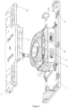
Figure 1 is the first perspective view of the toilet seat tool in the embodiment; -
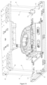
Figure 2 is the top view of the first base plate in the embodiment; -
Figure 3 is the top view of the second base plate in the embodiment; -
Figure 4 is the perspective view of the toilet seat in the embodiment; -
Figure 5 is the perspective view of the second base plate and the lower part of the seat in the embodiment; -
Figure 6 is the perspective view of the toilet seat and the toilet seat tool in the embodiment; -
Figure 7 is the plan view of the first profiling groove and the second profiling groove after fitting in the embodiment; -
Figure 8 is the schematic diagram of the connection between the positioning notch and the hook part in the embodiment; -
Figure 9 is the partial enlarged view of D-D inFigure 2 ; -
Figure 10 is the second perspective view of the toilet seat tool in the embodiment; - Description of reference signs: 1 First base plate; 11 First guide post; 2 First worktable; 3 First profiling groove; 31 Arc-shaped part; 32 Straight-line part; 33 Lifting mechanism; 331 Driving mechanism; 332 Lifting Part; 34 Positioning notch; 4 Second base plate; 41 Second guide post; 5 Second worktable; 6 Second profiling groove; 61 Sucker; 7 Air circuit box; 8 Electric circuit box; 9 Guide shaft; 10 Toilet seat; 101 Upper part of seat; 102 Lower part of seat; 103 Hook part.
- The invention is further described in detail below in combination with the attached drawings.
- As shown in
Figure 4 , thetoilet seat 10 that can be matched with the welding tool has the following features, including the upper part of theseat 101, the lower part of theseat 102 and thehook part 103. The upper part of the seat fits up and down with the lower part of the seat. The upper part of theseat 101, the lower part of theseat 102 and thehook part 103 are all made of thermoplastic resin and are obtained by injection molding. Ahook part 103 is arranged on both sides of the upper part of theseat 101. Thehook part 103 is L-shaped and bent upward. One end is connected to the upper part of theseat 101, and the other end is a free one; the hook part can be matched with the positioning notch. - The
first base plate 1, thesecond base plate 4, thesucker 61 and thelifting mechanism 33 mentioned in the invention are controlled by an external machine and driven by it to operate. Any machine and equipment that can provide power can be used to drive the the corresponding parts of the tool for operation. The selection and structure of the machine and equipment will not be repeated in the patent, nor will it be the object to be protected by the invention. - As shown in
figure 1-3 , the invention provides a toilet seat welding tool which comprises afirst base plate 1, afirst worktable 2, afirst profiling groove 3, asecond base plate 4, asecond worktable 5 and asecond profiling groove 6; thefirst worktable 2 is arranged in the middle area of thefirst base plate 1, and thefirst profiling groove 3 is arranged on thefirst worktable 2; thesecond worktable 5 is arranged in the middle area of thesecond base plate 4, and thesecond profiling groove 6 is arranged on thesecond worktable 5; thesecond base plate 4 is inverted on thefirst base plate 1, the position of thesecond worktable 5 corresponds to that of thefirst worktable 2, which can make thefirst profiling groove 3 and thesecond profiling groove 6 fit up and down; as shown inFigure 8 , the two sides of thefirst profiling groove 3 are provided with positioningnotches 34. Invert the upper part of theseat 101 to be welded into thefirst profiling groove 3, with the surface of the upper part of theseat 101 fitting with the surface of thefirst profiling groove 3 so that thehook parts 103 on both sides of the upper part of theseat 101 are well embedded into thepositioning notches 34, and then the lower part of theseat 102 fits above the upper part of theseat 101 by inverting the second base, and the welding edge can fit, so as to facilitate the subsequent friction welding; through the positioning notches on both sides of thefirst profiling groove 3, the welding position of thetoilet seat 10 can be effectively fixed without adding other parts, which is efficient, convenient and lower in cost. - When the first base plate and the second base plate need to be bonded in the way of left-right bonding, the upper part of the seat and the lower part of the seat are vertically placed in the form of left-right bonding, and the toilet seat is fixed in the first profiling groove and the second profiling groove according to the tool structure in this embodiment. In other embodiments, friction welding can still be completed in the way of left-right bonding after reading the way of up-down bonding according to the situation, which is a frequently used technical means readily conceived of by those skilled in the art.
- As shown in
Figure 5 , further, at least twosuckers 61 are evenly distributed in thesecond profiling groove 6. In this embodiment, foursuckers 61 evenly distributed up and down are used. Setting of thesuckers 61 in thesecond profiling groove 6 can better absorb the inverted lower part of theseat 102, and will not make the lower part of theseat 102 move freely when suspended and during friction welding, so as to better improve the welding effect. - As shown in
Figure 7 , further, at least two first guide posts are symmetrically arranged on both sides of thefirst base plate 1, and at least two second guide posts are arranged at the position corresponding to the first guide post on thesecond base plate 4; the first guide post and the second guide post are hollow structures, and the sizes of the hollow parts are the same; when the first base plate and the second base plate are fitted up and down, they can be fitted and positioned by inserting the guide shafts into the hollow structure part of the first guide post and the second guide post. As shown inFigure 10 , in this embodiment, four first guide posts 11 and second guide posts 41 are respectively arranged at the edge of thefirst base plate 1 and thesecond base plate 4. Before the seat is welded, theguide shaft 9 can be embedded into the hollow cavity of thefirst guide post 11. Through the cooperation of the guide shaft and the guide post, the second guide post sleeve is arranged above the guide shaft to position the upper and lower base plates so as to locate the position of the upper and lower profiling grooves; when welding is required, theguide shaft 9 is removed to fit the upper and lower profiling grooves more conveniently. - As shown in
Figures 1 ,6 and7 , further, thefirst profiling groove 3 is provided with at least two liftingmechanisms 33, which comprises adriving mechanism 331 and alifting part 332; the liftingpart 332 is arranged on thedriving mechanism 331 and thedriving mechanism 331 is arranged in the first worktable; the liftingparts 332 are evenly distributed in thefirst profiling groove 3 and can move up and down relative to the position of thefirst profiling groove 3. In this embodiment, four liftingmechanisms 33 are evenly distributed in thefirst profiling groove 3. After friction welding is completed, the seat volume will expand slightly due to the heat energy generated by welding, and then form a closer fit with the internal structure of thefirst profiling groove 3, which is not conducive for the staff to take out the seat; thelifting mechanism 33 can lift the toilet seat 10 a certain distance in the vertical direction from the lower part of the seat, so that it can be smoothly separated from the surface of thefirst profiling groove 3, which is convenient for the staff to take out the weldedtoilet seat 10. - As shown in
Figure 2 , further, one side of thefirst base plate 1 is provided with an air circuit box 7 and an electric circuit box 8. An air circuit box 7 and an electric circuit box 8 are arranged on one side, which can better provide driving power required for the operation of the tool. - As shown in
Figures 2 and9 , further, thefirst profiling groove 3 comprises an arc-shapedpart 31 and a straight-line part 32. The shape of the longitudinal section of the straight-line part is a downward inclined acute angle, with the angle range of the acute angle between 30° and 90°. In this embodiment, the straight-line part 32 of thefirst profiling groove 3 corresponds to the shape of the straight-line part in the upper part of theseat 101, and the shape of the straight-line part of the second profiling groove and the lower part of the seat also correspond to each other. The acute angle inclined downward by a certain angle can keep mutual bonding on both sides so that the upper part of theseat 101 is placed in thefirst profiling groove 3, or the lower part of the seat is placed in the second profiling groove for ensuring more accurate positioning and making the tail gap difference be within the control range. Such a design can better keep the welding position of the toilet seat and achieve better welding effect. - As shown in
Figures 1 ,6 and7 , further, the part where thefirst profiling groove 3 and thesecond profiling groove 6 are bonded adopts a rubber layer, and the hardness of the rubber layer is 85±5 Shore A, which is moderate. Otherwise, if it is too soft, it will cause excessive deformation of the tool; if it is too hard, it will lead to scratch of the product. Thefirst profiling groove 3 and thesecond profiling groove 6 are divided into a concave area in the middle, with the edge raised upward; the upper and lower parts of thetoilet seat 10 can be placed in the concave area between thefirst profiling groove 3 and thesecond profiling groove 6, and the upward raised area around can play a role of protection and fitting. The rubber ring is used at the fitting part between thefirst profiling groove 3 and thesecond profiling groove 6, which can play a buffer role, prevent the damage of thefirst profiling groove 3 and thesecond profiling groove 6, and improve the service life of the tool. - Those skilled in the art, upon considering the instructions and practicing the invention disclosed herein, may readily conceive of other implementation schemes of the invention. The application aims to cover any variation, purpose or adaptive change of the invention, which follows the general principles of the invention and includes the common general knowledge or frequently used technical means in the technical field not disclosed in the disclosure. The instructions and embodiments are only regarded as exemplary, and the real scope and spirit of the invention are indicated by the following claims.
- It should be understood that the invention is not limited to the precise structure described above and shown in the drawings, and various modifications and alterations can be made without departing from its scope.
Claims (10)
- A toilet seat connection tool, characterized in that it comprises a first base plate, a first work table, a first profiling groove, a second base plate, a second worktable and a second profiling groove;the first worktable being arranged in the middle area of the first base plate, and the first profiling groove being arranged on the first worktable; the second worktable being arranged in the middle area of the second base plate, and the second profiling groove being arranged on the second worktable;the second base plate being inverted on the first base plate, and the position of the second worktable corresponding to that of the first worktable, so that the first profiling groove and the second profiling groove can be fitted up and down;both sides of the first profiling groove being provided with positioning notches.
- A toilet seat connection tool according to claim 1, characterized in that at least two suckers are evenly distributed in the second profiling groove.
- A toilet seat connection tool according to claim 1 or 2, characterized in that at least two first guide posts are symmetrically arranged on both sides of the first base plate, and at least two second guide posts are arranged at the position corresponding to the first guide post on the second base plate; the first guide post and the second guide post being hollow structures, and the sizes of the hollow parts being the same; and in that, when the first base plate and the second base plate are fitted up and down, they can be fitted and positioned by inserting the guide shafts into the hollow structure part of the first guide post and the second guide post.
- A toilet seat connection tool according to claim 1, 2 or 3, characterized in that at least two lifting mechanisms are arranged in the first profiling groove, the lifting mechanism comprising a driving mechanism and a lifting part, the lifting part being arranged on the driving mechanism, the driving mechanism being arranged in the first worktable, wherein the lifting parts are evenly distributed in the first profiling groove and can move up and down relative to the position of the first profiling groove.
- A toilet seat connection tool according to claim 4, characterized in that one side of the first base plate is provided with an air circuit box and an electric circuit box.
- A toilet seat connection tool according to one of the preceding claims, characterized in that the first profiling groove comprises an arc-shaped part and a straight-line part, the shape of the longitudinal section of the straight-line part being a downward inclined acute angle, with the angle range of the acute angle between 30° and 90°.
- A toilet seat connection tool according to one of the preceding claims, characterized in that the part where the first profiling groove and the second profiling groove are fitted adopts a rubber layer, and the hardness of the rubber layer is 85±5 Shore A.
- A toilet seat connection tool according to one of the preceding claims being a toilet seat welding tool, in particular a toilet seat vibration welding tool.
- A toilet seat, characterized in that it comprises an upper part of the seat, a lower part of the seat and a hook part; that the upper part of the seat and the lower part of the seat can be fitted up and down; and that the two sides of the upper part of the seat are provided with the hook part, the hook part comprising an L shape of vertical part and horizontal part, which is bent upward; wherein the vertical part of the hook part can be embedded into one of the positioning notches of a toilet seat connection tool of any one of claims 1 to 8.
- A toilet seat according to claim 9, characterized in that parts of the toilet seat are welded with each other.
Applications Claiming Priority (1)
| Application Number | Priority Date | Filing Date | Title |
|---|---|---|---|
| CN202220842578.1U CN217891904U (en) | 2022-04-09 | 2022-04-09 | Closestool seat ring welding tool and closestool seat ring applying same |
Publications (2)
| Publication Number | Publication Date |
|---|---|
| EP4257342A1 true EP4257342A1 (en) | 2023-10-11 |
| EP4257342B1 EP4257342B1 (en) | 2024-09-04 |
Family
ID=82780877
Family Applications (1)
| Application Number | Title | Priority Date | Filing Date |
|---|---|---|---|
| EP22187485.2A Active EP4257342B1 (en) | 2022-04-09 | 2022-07-28 | A toilet seat connection tool and a toilet seat applying same |
Country Status (5)
| Country | Link |
|---|---|
| EP (1) | EP4257342B1 (en) |
| CN (1) | CN217891904U (en) |
| DK (1) | DK4257342T3 (en) |
| ES (1) | ES2989976T3 (en) |
| PL (1) | PL4257342T3 (en) |
Citations (3)
| Publication number | Priority date | Publication date | Assignee | Title |
|---|---|---|---|---|
| JPH1023992A (en) * | 1996-07-15 | 1998-01-27 | Matsushita Electric Ind Co Ltd | Toilet seat unit |
| JP2014018283A (en) * | 2012-07-13 | 2014-02-03 | Panasonic Corp | Toilet seat and method for manufacturing the same |
| JP2018082817A (en) * | 2016-11-22 | 2018-05-31 | パナソニックIpマネジメント株式会社 | Toilet seat manufacturing method |
-
2022
- 2022-04-09 CN CN202220842578.1U patent/CN217891904U/en active Active
- 2022-07-28 DK DK22187485.2T patent/DK4257342T3/en active
- 2022-07-28 ES ES22187485T patent/ES2989976T3/en active Active
- 2022-07-28 EP EP22187485.2A patent/EP4257342B1/en active Active
- 2022-07-28 PL PL22187485.2T patent/PL4257342T3/en unknown
Patent Citations (3)
| Publication number | Priority date | Publication date | Assignee | Title |
|---|---|---|---|---|
| JPH1023992A (en) * | 1996-07-15 | 1998-01-27 | Matsushita Electric Ind Co Ltd | Toilet seat unit |
| JP2014018283A (en) * | 2012-07-13 | 2014-02-03 | Panasonic Corp | Toilet seat and method for manufacturing the same |
| JP2018082817A (en) * | 2016-11-22 | 2018-05-31 | パナソニックIpマネジメント株式会社 | Toilet seat manufacturing method |
Also Published As
| Publication number | Publication date |
|---|---|
| ES2989976T3 (en) | 2024-11-28 |
| EP4257342B1 (en) | 2024-09-04 |
| PL4257342T3 (en) | 2024-11-18 |
| CN217891904U (en) | 2022-11-25 |
| DK4257342T3 (en) | 2024-09-30 |
Similar Documents
| Publication | Publication Date | Title |
|---|---|---|
| CN210837808U (en) | a fitting device | |
| CN108115890B (en) | A mold for integral injection molding of glass and nail post | |
| EP4257342B1 (en) | A toilet seat connection tool and a toilet seat applying same | |
| CN115533068A (en) | A mold for mechanical casting | |
| CN209079225U (en) | Photocuring 3D printer | |
| CN212670270U (en) | Bridge support with adjusting function | |
| CN111251158A (en) | A ceramic tile cutting device for construction engineering | |
| CN205587636U (en) | Portable casting machine plunger tip device | |
| CN212145363U (en) | High-efficient fixed working platform is used in mould processing | |
| CN101456259A (en) | Thermosol treatment tool, hot melting device and material stitching method using the thermosol treatment tool | |
| CN214442050U (en) | A bending machine with easy height adjustment | |
| CN114211746A (en) | 3D printing assembly, printing platform and leveling method of platform | |
| CN213052139U (en) | Levelling tool for thin plate of cruise ship | |
| CN206169594U (en) | Square shaft side position pressure equipment mechanism | |
| CN208020714U (en) | A kind of die station device | |
| CN219466842U (en) | A fine runner mold base with precise mold closing | |
| CN217839679U (en) | Limiting device for steel backing plate of bridge support | |
| CN106738585A (en) | One kind foaming vulcanizer | |
| CN222935158U (en) | Winebottle fixing device for filling machine | |
| CN218664126U (en) | Blocking mechanism | |
| CN211350815U (en) | a liquid injection machine | |
| CN214197853U (en) | Cradle working height adjusting mechanism | |
| CN207465463U (en) | A kind of automatic backform device of ceramics automatic rolling machine | |
| CN213317368U (en) | Pin arranging device for chip pins | |
| CN222536100U (en) | A dual-purpose mechanism for floating and positioning |
Legal Events
| Date | Code | Title | Description |
|---|---|---|---|
| PUAI | Public reference made under article 153(3) epc to a published international application that has entered the european phase |
Free format text: ORIGINAL CODE: 0009012 |
|
| STAA | Information on the status of an ep patent application or granted ep patent |
Free format text: STATUS: REQUEST FOR EXAMINATION WAS MADE |
|
| 17P | Request for examination filed |
Effective date: 20230313 |
|
| AK | Designated contracting states |
Kind code of ref document: A1 Designated state(s): AL AT BE BG CH CY CZ DE DK EE ES FI FR GB GR HR HU IE IS IT LI LT LU LV MC MK MT NL NO PL PT RO RS SE SI SK SM TR |
|
| GRAP | Despatch of communication of intention to grant a patent |
Free format text: ORIGINAL CODE: EPIDOSNIGR1 |
|
| STAA | Information on the status of an ep patent application or granted ep patent |
Free format text: STATUS: GRANT OF PATENT IS INTENDED |
|
| RIC1 | Information provided on ipc code assigned before grant |
Ipc: B29L 31/00 20060101ALN20240306BHEP Ipc: B29C 65/48 20060101ALN20240306BHEP Ipc: B29C 65/00 20060101ALI20240306BHEP Ipc: A47K 13/02 20060101ALI20240306BHEP Ipc: B29C 65/78 20060101ALI20240306BHEP Ipc: B29C 65/06 20060101AFI20240306BHEP |
|
| RBV | Designated contracting states (corrected) |
Designated state(s): AL AT BE BG CH CY CZ DE DK EE ES FI FR GB GR HR HU IE IS IT LI LT LU LV MC MK MT NL NO PL PT RO RS SE SI SK SM TR |
|
| INTG | Intention to grant announced |
Effective date: 20240410 |
|
| GRAS | Grant fee paid |
Free format text: ORIGINAL CODE: EPIDOSNIGR3 |
|
| GRAA | (expected) grant |
Free format text: ORIGINAL CODE: 0009210 |
|
| STAA | Information on the status of an ep patent application or granted ep patent |
Free format text: STATUS: THE PATENT HAS BEEN GRANTED |
|
| REG | Reference to a national code |
Ref country code: DE Ref legal event code: R082 Ref document number: 602022005836 Country of ref document: DE Representative=s name: SZYNKA SMORODIN PATENTANWAELTE PARTNERSCHAFT M, DE Ref country code: DE Ref legal event code: R082 Ref document number: 602022005836 Country of ref document: DE Representative=s name: KOENIG SZYNKA TILMANN VON RENESSE PATENTANWAEL, DE |
|
| AK | Designated contracting states |
Kind code of ref document: B1 Designated state(s): AL AT BE BG CH CY CZ DE DK EE ES FI FR GB GR HR HU IE IS IT LI LT LU LV MC MK MT NL NO PL PT RO RS SE SI SK SM TR |
|
| REG | Reference to a national code |
Ref country code: GB Ref legal event code: FG4D |
|
| REG | Reference to a national code |
Ref country code: CH Ref legal event code: EP |
|
| P01 | Opt-out of the competence of the unified patent court (upc) registered |
Free format text: CASE NUMBER: APP_46798/2024 Effective date: 20240813 |
|
| REG | Reference to a national code |
Ref country code: IE Ref legal event code: FG4D |
|
| REG | Reference to a national code |
Ref country code: DE Ref legal event code: R096 Ref document number: 602022005836 Country of ref document: DE |
|
| REG | Reference to a national code |
Ref country code: DK Ref legal event code: T3 Effective date: 20240925 |
|
| REG | Reference to a national code |
Ref country code: ES Ref legal event code: FG2A Ref document number: 2989976 Country of ref document: ES Kind code of ref document: T3 Effective date: 20241128 |
|
| REG | Reference to a national code |
Ref country code: LT Ref legal event code: MG9D |
|
| REG | Reference to a national code |
Ref country code: NL Ref legal event code: MP Effective date: 20240904 |
|
| PG25 | Lapsed in a contracting state [announced via postgrant information from national office to epo] |
Ref country code: NO Free format text: LAPSE BECAUSE OF FAILURE TO SUBMIT A TRANSLATION OF THE DESCRIPTION OR TO PAY THE FEE WITHIN THE PRESCRIBED TIME-LIMIT Effective date: 20241204 |
|
| PG25 | Lapsed in a contracting state [announced via postgrant information from national office to epo] |
Ref country code: GR Free format text: LAPSE BECAUSE OF FAILURE TO SUBMIT A TRANSLATION OF THE DESCRIPTION OR TO PAY THE FEE WITHIN THE PRESCRIBED TIME-LIMIT Effective date: 20241205 Ref country code: FI Free format text: LAPSE BECAUSE OF FAILURE TO SUBMIT A TRANSLATION OF THE DESCRIPTION OR TO PAY THE FEE WITHIN THE PRESCRIBED TIME-LIMIT Effective date: 20240904 |
|
| PG25 | Lapsed in a contracting state [announced via postgrant information from national office to epo] |
Ref country code: BG Free format text: LAPSE BECAUSE OF FAILURE TO SUBMIT A TRANSLATION OF THE DESCRIPTION OR TO PAY THE FEE WITHIN THE PRESCRIBED TIME-LIMIT Effective date: 20240904 |
|
| PG25 | Lapsed in a contracting state [announced via postgrant information from national office to epo] |
Ref country code: LV Free format text: LAPSE BECAUSE OF FAILURE TO SUBMIT A TRANSLATION OF THE DESCRIPTION OR TO PAY THE FEE WITHIN THE PRESCRIBED TIME-LIMIT Effective date: 20240904 |
|
| PG25 | Lapsed in a contracting state [announced via postgrant information from national office to epo] |
Ref country code: HR Free format text: LAPSE BECAUSE OF FAILURE TO SUBMIT A TRANSLATION OF THE DESCRIPTION OR TO PAY THE FEE WITHIN THE PRESCRIBED TIME-LIMIT Effective date: 20240904 |
|
| PG25 | Lapsed in a contracting state [announced via postgrant information from national office to epo] |
Ref country code: RS Free format text: LAPSE BECAUSE OF FAILURE TO SUBMIT A TRANSLATION OF THE DESCRIPTION OR TO PAY THE FEE WITHIN THE PRESCRIBED TIME-LIMIT Effective date: 20241204 |
|
| PG25 | Lapsed in a contracting state [announced via postgrant information from national office to epo] |
Ref country code: RS Free format text: LAPSE BECAUSE OF FAILURE TO SUBMIT A TRANSLATION OF THE DESCRIPTION OR TO PAY THE FEE WITHIN THE PRESCRIBED TIME-LIMIT Effective date: 20241204 Ref country code: NO Free format text: LAPSE BECAUSE OF FAILURE TO SUBMIT A TRANSLATION OF THE DESCRIPTION OR TO PAY THE FEE WITHIN THE PRESCRIBED TIME-LIMIT Effective date: 20241204 Ref country code: LV Free format text: LAPSE BECAUSE OF FAILURE TO SUBMIT A TRANSLATION OF THE DESCRIPTION OR TO PAY THE FEE WITHIN THE PRESCRIBED TIME-LIMIT Effective date: 20240904 Ref country code: HR Free format text: LAPSE BECAUSE OF FAILURE TO SUBMIT A TRANSLATION OF THE DESCRIPTION OR TO PAY THE FEE WITHIN THE PRESCRIBED TIME-LIMIT Effective date: 20240904 Ref country code: GR Free format text: LAPSE BECAUSE OF FAILURE TO SUBMIT A TRANSLATION OF THE DESCRIPTION OR TO PAY THE FEE WITHIN THE PRESCRIBED TIME-LIMIT Effective date: 20241205 Ref country code: FI Free format text: LAPSE BECAUSE OF FAILURE TO SUBMIT A TRANSLATION OF THE DESCRIPTION OR TO PAY THE FEE WITHIN THE PRESCRIBED TIME-LIMIT Effective date: 20240904 Ref country code: BG Free format text: LAPSE BECAUSE OF FAILURE TO SUBMIT A TRANSLATION OF THE DESCRIPTION OR TO PAY THE FEE WITHIN THE PRESCRIBED TIME-LIMIT Effective date: 20240904 |
|
| PG25 | Lapsed in a contracting state [announced via postgrant information from national office to epo] |
Ref country code: NL Free format text: LAPSE BECAUSE OF FAILURE TO SUBMIT A TRANSLATION OF THE DESCRIPTION OR TO PAY THE FEE WITHIN THE PRESCRIBED TIME-LIMIT Effective date: 20240904 |
|
| REG | Reference to a national code |
Ref country code: DE Ref legal event code: R082 Ref document number: 602022005836 Country of ref document: DE Representative=s name: SZYNKA SMORODIN PATENTANWAELTE PARTNERSCHAFT M, DE |
|
| PG25 | Lapsed in a contracting state [announced via postgrant information from national office to epo] |
Ref country code: PT Free format text: LAPSE BECAUSE OF FAILURE TO SUBMIT A TRANSLATION OF THE DESCRIPTION OR TO PAY THE FEE WITHIN THE PRESCRIBED TIME-LIMIT Effective date: 20250106 Ref country code: IS Free format text: LAPSE BECAUSE OF FAILURE TO SUBMIT A TRANSLATION OF THE DESCRIPTION OR TO PAY THE FEE WITHIN THE PRESCRIBED TIME-LIMIT Effective date: 20250104 |
|
| PG25 | Lapsed in a contracting state [announced via postgrant information from national office to epo] |
Ref country code: SM Free format text: LAPSE BECAUSE OF FAILURE TO SUBMIT A TRANSLATION OF THE DESCRIPTION OR TO PAY THE FEE WITHIN THE PRESCRIBED TIME-LIMIT Effective date: 20240904 Ref country code: RO Free format text: LAPSE BECAUSE OF FAILURE TO SUBMIT A TRANSLATION OF THE DESCRIPTION OR TO PAY THE FEE WITHIN THE PRESCRIBED TIME-LIMIT Effective date: 20240904 |
|
| PG25 | Lapsed in a contracting state [announced via postgrant information from national office to epo] |
Ref country code: EE Free format text: LAPSE BECAUSE OF FAILURE TO SUBMIT A TRANSLATION OF THE DESCRIPTION OR TO PAY THE FEE WITHIN THE PRESCRIBED TIME-LIMIT Effective date: 20240904 |
|
| PG25 | Lapsed in a contracting state [announced via postgrant information from national office to epo] |
Ref country code: CZ Free format text: LAPSE BECAUSE OF FAILURE TO SUBMIT A TRANSLATION OF THE DESCRIPTION OR TO PAY THE FEE WITHIN THE PRESCRIBED TIME-LIMIT Effective date: 20240904 |
|
| PG25 | Lapsed in a contracting state [announced via postgrant information from national office to epo] |
Ref country code: SK Free format text: LAPSE BECAUSE OF FAILURE TO SUBMIT A TRANSLATION OF THE DESCRIPTION OR TO PAY THE FEE WITHIN THE PRESCRIBED TIME-LIMIT Effective date: 20240904 |
|
| REG | Reference to a national code |
Ref country code: DE Ref legal event code: R097 Ref document number: 602022005836 Country of ref document: DE |
|
| PLBE | No opposition filed within time limit |
Free format text: ORIGINAL CODE: 0009261 |
|
| STAA | Information on the status of an ep patent application or granted ep patent |
Free format text: STATUS: NO OPPOSITION FILED WITHIN TIME LIMIT |
|
| 26N | No opposition filed |
Effective date: 20250605 |
|
| PG25 | Lapsed in a contracting state [announced via postgrant information from national office to epo] |
Ref country code: SE Free format text: LAPSE BECAUSE OF FAILURE TO SUBMIT A TRANSLATION OF THE DESCRIPTION OR TO PAY THE FEE WITHIN THE PRESCRIBED TIME-LIMIT Effective date: 20240904 |
|
| PGFP | Annual fee paid to national office [announced via postgrant information from national office to epo] |
Ref country code: ES Payment date: 20250819 Year of fee payment: 4 |
|
| PGFP | Annual fee paid to national office [announced via postgrant information from national office to epo] |
Ref country code: DK Payment date: 20250722 Year of fee payment: 4 Ref country code: DE Payment date: 20250722 Year of fee payment: 4 |
|
| PGFP | Annual fee paid to national office [announced via postgrant information from national office to epo] |
Ref country code: TR Payment date: 20250724 Year of fee payment: 4 Ref country code: PL Payment date: 20250723 Year of fee payment: 4 Ref country code: IT Payment date: 20250731 Year of fee payment: 4 |
|
| PGFP | Annual fee paid to national office [announced via postgrant information from national office to epo] |
Ref country code: AT Payment date: 20251020 Year of fee payment: 4 |
|
| PGFP | Annual fee paid to national office [announced via postgrant information from national office to epo] |
Ref country code: CH Payment date: 20250801 Year of fee payment: 4 |
|
| REG | Reference to a national code |
Ref country code: AT Ref legal event code: UEP Ref document number: 1719938 Country of ref document: AT Kind code of ref document: T Effective date: 20240904 |
|
| PG25 | Lapsed in a contracting state [announced via postgrant information from national office to epo] |
Ref country code: LU Free format text: LAPSE BECAUSE OF NON-PAYMENT OF DUE FEES Effective date: 20250728 |
|
| REG | Reference to a national code |
Ref country code: BE Ref legal event code: MM Effective date: 20250731 |
|
| PG25 | Lapsed in a contracting state [announced via postgrant information from national office to epo] |
Ref country code: BE Free format text: LAPSE BECAUSE OF NON-PAYMENT OF DUE FEES Effective date: 20250731 |
|
| PG25 | Lapsed in a contracting state [announced via postgrant information from national office to epo] |
Ref country code: FR Free format text: LAPSE BECAUSE OF NON-PAYMENT OF DUE FEES Effective date: 20250731 |