EP4257308A2 - Facer for end fusion of polyolefin pipes - Google Patents
Facer for end fusion of polyolefin pipes Download PDFInfo
- Publication number
- EP4257308A2 EP4257308A2 EP23193632.9A EP23193632A EP4257308A2 EP 4257308 A2 EP4257308 A2 EP 4257308A2 EP 23193632 A EP23193632 A EP 23193632A EP 4257308 A2 EP4257308 A2 EP 4257308A2
- Authority
- EP
- European Patent Office
- Prior art keywords
- facer
- guide rail
- drive unit
- output shaft
- pipe
- Prior art date
- Legal status (The legal status is an assumption and is not a legal conclusion. Google has not performed a legal analysis and makes no representation as to the accuracy of the status listed.)
- Pending
Links
- 229920000098 polyolefin Polymers 0.000 title claims abstract description 43
- 230000004927 fusion Effects 0.000 title abstract description 20
- 230000000712 assembly Effects 0.000 claims description 9
- 238000000429 assembly Methods 0.000 claims description 9
- 238000006073 displacement reaction Methods 0.000 claims description 7
- 238000003491 array Methods 0.000 claims description 4
- 230000005540 biological transmission Effects 0.000 claims description 2
- 230000008878 coupling Effects 0.000 claims description 2
- 238000010168 coupling process Methods 0.000 claims description 2
- 238000005859 coupling reaction Methods 0.000 claims description 2
- 239000000463 material Substances 0.000 abstract description 2
- 238000000034 method Methods 0.000 description 4
- 239000006185 dispersion Substances 0.000 description 2
- 239000004677 Nylon Substances 0.000 description 1
- 238000010276 construction Methods 0.000 description 1
- 230000013011 mating Effects 0.000 description 1
- 229920001778 nylon Polymers 0.000 description 1
- 230000000737 periodic effect Effects 0.000 description 1
Images


Classifications
-
- B—PERFORMING OPERATIONS; TRANSPORTING
- B26—HAND CUTTING TOOLS; CUTTING; SEVERING
- B26D—CUTTING; DETAILS COMMON TO MACHINES FOR PERFORATING, PUNCHING, CUTTING-OUT, STAMPING-OUT OR SEVERING
- B26D1/00—Cutting through work characterised by the nature or movement of the cutting member or particular materials not otherwise provided for; Apparatus or machines therefor; Cutting members therefor
- B26D1/01—Cutting through work characterised by the nature or movement of the cutting member or particular materials not otherwise provided for; Apparatus or machines therefor; Cutting members therefor involving a cutting member which does not travel with the work
- B26D1/12—Cutting through work characterised by the nature or movement of the cutting member or particular materials not otherwise provided for; Apparatus or machines therefor; Cutting members therefor involving a cutting member which does not travel with the work having a cutting member moving about an axis
- B26D1/25—Cutting through work characterised by the nature or movement of the cutting member or particular materials not otherwise provided for; Apparatus or machines therefor; Cutting members therefor involving a cutting member which does not travel with the work having a cutting member moving about an axis with a non-circular cutting member
- B26D1/26—Cutting through work characterised by the nature or movement of the cutting member or particular materials not otherwise provided for; Apparatus or machines therefor; Cutting members therefor involving a cutting member which does not travel with the work having a cutting member moving about an axis with a non-circular cutting member moving about an axis substantially perpendicular to the line of cut
- B26D1/28—Cutting through work characterised by the nature or movement of the cutting member or particular materials not otherwise provided for; Apparatus or machines therefor; Cutting members therefor involving a cutting member which does not travel with the work having a cutting member moving about an axis with a non-circular cutting member moving about an axis substantially perpendicular to the line of cut and rotating continuously in one direction during cutting
-
- B—PERFORMING OPERATIONS; TRANSPORTING
- B23—MACHINE TOOLS; METAL-WORKING NOT OTHERWISE PROVIDED FOR
- B23B—TURNING; BORING
- B23B5/00—Turning-machines or devices specially adapted for particular work; Accessories specially adapted therefor
- B23B5/08—Turning-machines or devices specially adapted for particular work; Accessories specially adapted therefor for turning axles, bars, rods, tubes, rolls, i.e. shaft-turning lathes, roll lathes; Centreless turning
-
- B—PERFORMING OPERATIONS; TRANSPORTING
- B23—MACHINE TOOLS; METAL-WORKING NOT OTHERWISE PROVIDED FOR
- B23B—TURNING; BORING
- B23B5/00—Turning-machines or devices specially adapted for particular work; Accessories specially adapted therefor
- B23B5/16—Turning-machines or devices specially adapted for particular work; Accessories specially adapted therefor for bevelling, chamfering, or deburring the ends of bars or tubes
-
- B—PERFORMING OPERATIONS; TRANSPORTING
- B26—HAND CUTTING TOOLS; CUTTING; SEVERING
- B26D—CUTTING; DETAILS COMMON TO MACHINES FOR PERFORATING, PUNCHING, CUTTING-OUT, STAMPING-OUT OR SEVERING
- B26D3/00—Cutting work characterised by the nature of the cut made; Apparatus therefor
- B26D3/16—Cutting rods or tubes transversely
- B26D3/166—Trimming tube-ends
-
- B—PERFORMING OPERATIONS; TRANSPORTING
- B26—HAND CUTTING TOOLS; CUTTING; SEVERING
- B26D—CUTTING; DETAILS COMMON TO MACHINES FOR PERFORATING, PUNCHING, CUTTING-OUT, STAMPING-OUT OR SEVERING
- B26D7/00—Details of apparatus for cutting, cutting-out, stamping-out, punching, perforating, or severing by means other than cutting
- B26D7/0006—Means for guiding the cutter
-
- B—PERFORMING OPERATIONS; TRANSPORTING
- B26—HAND CUTTING TOOLS; CUTTING; SEVERING
- B26D—CUTTING; DETAILS COMMON TO MACHINES FOR PERFORATING, PUNCHING, CUTTING-OUT, STAMPING-OUT OR SEVERING
- B26D7/00—Details of apparatus for cutting, cutting-out, stamping-out, punching, perforating, or severing by means other than cutting
- B26D7/01—Means for holding or positioning work
-
- B—PERFORMING OPERATIONS; TRANSPORTING
- B26—HAND CUTTING TOOLS; CUTTING; SEVERING
- B26D—CUTTING; DETAILS COMMON TO MACHINES FOR PERFORATING, PUNCHING, CUTTING-OUT, STAMPING-OUT OR SEVERING
- B26D7/00—Details of apparatus for cutting, cutting-out, stamping-out, punching, perforating, or severing by means other than cutting
- B26D7/06—Arrangements for feeding or delivering work of other than sheet, web, or filamentary form
- B26D7/0616—Arrangements for feeding or delivering work of other than sheet, web, or filamentary form by carriages, e.g. for slicing machines
-
- B—PERFORMING OPERATIONS; TRANSPORTING
- B26—HAND CUTTING TOOLS; CUTTING; SEVERING
- B26D—CUTTING; DETAILS COMMON TO MACHINES FOR PERFORATING, PUNCHING, CUTTING-OUT, STAMPING-OUT OR SEVERING
- B26D7/00—Details of apparatus for cutting, cutting-out, stamping-out, punching, perforating, or severing by means other than cutting
- B26D7/26—Means for mounting or adjusting the cutting member; Means for adjusting the stroke of the cutting member
- B26D7/2614—Means for mounting the cutting member
-
- B—PERFORMING OPERATIONS; TRANSPORTING
- B29—WORKING OF PLASTICS; WORKING OF SUBSTANCES IN A PLASTIC STATE IN GENERAL
- B29C—SHAPING OR JOINING OF PLASTICS; SHAPING OF MATERIAL IN A PLASTIC STATE, NOT OTHERWISE PROVIDED FOR; AFTER-TREATMENT OF THE SHAPED PRODUCTS, e.g. REPAIRING
- B29C65/00—Joining or sealing of preformed parts, e.g. welding of plastics materials; Apparatus therefor
- B29C65/02—Joining or sealing of preformed parts, e.g. welding of plastics materials; Apparatus therefor by heating, with or without pressure
-
- B—PERFORMING OPERATIONS; TRANSPORTING
- B29—WORKING OF PLASTICS; WORKING OF SUBSTANCES IN A PLASTIC STATE IN GENERAL
- B29C—SHAPING OR JOINING OF PLASTICS; SHAPING OF MATERIAL IN A PLASTIC STATE, NOT OTHERWISE PROVIDED FOR; AFTER-TREATMENT OF THE SHAPED PRODUCTS, e.g. REPAIRING
- B29C66/00—General aspects of processes or apparatus for joining preformed parts
- B29C66/01—General aspects dealing with the joint area or with the area to be joined
- B29C66/02—Preparation of the material, in the area to be joined, prior to joining or welding
- B29C66/022—Mechanical pre-treatments, e.g. reshaping
- B29C66/0224—Mechanical pre-treatments, e.g. reshaping with removal of material
- B29C66/02241—Cutting, e.g. by using waterjets, or sawing
-
- B—PERFORMING OPERATIONS; TRANSPORTING
- B29—WORKING OF PLASTICS; WORKING OF SUBSTANCES IN A PLASTIC STATE IN GENERAL
- B29C—SHAPING OR JOINING OF PLASTICS; SHAPING OF MATERIAL IN A PLASTIC STATE, NOT OTHERWISE PROVIDED FOR; AFTER-TREATMENT OF THE SHAPED PRODUCTS, e.g. REPAIRING
- B29C66/00—General aspects of processes or apparatus for joining preformed parts
- B29C66/01—General aspects dealing with the joint area or with the area to be joined
- B29C66/05—Particular design of joint configurations
- B29C66/10—Particular design of joint configurations particular design of the joint cross-sections
- B29C66/11—Joint cross-sections comprising a single joint-segment, i.e. one of the parts to be joined comprising a single joint-segment in the joint cross-section
- B29C66/114—Single butt joints
- B29C66/1142—Single butt to butt joints
-
- B—PERFORMING OPERATIONS; TRANSPORTING
- B29—WORKING OF PLASTICS; WORKING OF SUBSTANCES IN A PLASTIC STATE IN GENERAL
- B29C—SHAPING OR JOINING OF PLASTICS; SHAPING OF MATERIAL IN A PLASTIC STATE, NOT OTHERWISE PROVIDED FOR; AFTER-TREATMENT OF THE SHAPED PRODUCTS, e.g. REPAIRING
- B29C66/00—General aspects of processes or apparatus for joining preformed parts
- B29C66/50—General aspects of joining tubular articles; General aspects of joining long products, i.e. bars or profiled elements; General aspects of joining single elements to tubular articles, hollow articles or bars; General aspects of joining several hollow-preforms to form hollow or tubular articles
- B29C66/51—Joining tubular articles, profiled elements or bars; Joining single elements to tubular articles, hollow articles or bars; Joining several hollow-preforms to form hollow or tubular articles
- B29C66/52—Joining tubular articles, bars or profiled elements
- B29C66/522—Joining tubular articles
- B29C66/5221—Joining tubular articles for forming coaxial connections, i.e. the tubular articles to be joined forming a zero angle relative to each other
-
- B—PERFORMING OPERATIONS; TRANSPORTING
- B29—WORKING OF PLASTICS; WORKING OF SUBSTANCES IN A PLASTIC STATE IN GENERAL
- B29C—SHAPING OR JOINING OF PLASTICS; SHAPING OF MATERIAL IN A PLASTIC STATE, NOT OTHERWISE PROVIDED FOR; AFTER-TREATMENT OF THE SHAPED PRODUCTS, e.g. REPAIRING
- B29C66/00—General aspects of processes or apparatus for joining preformed parts
- B29C66/70—General aspects of processes or apparatus for joining preformed parts characterised by the composition, physical properties or the structure of the material of the parts to be joined; Joining with non-plastics material
- B29C66/73—General aspects of processes or apparatus for joining preformed parts characterised by the composition, physical properties or the structure of the material of the parts to be joined; Joining with non-plastics material characterised by the intensive physical properties of the material of the parts to be joined, by the optical properties of the material of the parts to be joined, by the extensive physical properties of the parts to be joined, by the state of the material of the parts to be joined or by the material of the parts to be joined being a thermoplastic or a thermoset
- B29C66/739—General aspects of processes or apparatus for joining preformed parts characterised by the composition, physical properties or the structure of the material of the parts to be joined; Joining with non-plastics material characterised by the intensive physical properties of the material of the parts to be joined, by the optical properties of the material of the parts to be joined, by the extensive physical properties of the parts to be joined, by the state of the material of the parts to be joined or by the material of the parts to be joined being a thermoplastic or a thermoset characterised by the material of the parts to be joined being a thermoplastic or a thermoset
- B29C66/7392—General aspects of processes or apparatus for joining preformed parts characterised by the composition, physical properties or the structure of the material of the parts to be joined; Joining with non-plastics material characterised by the intensive physical properties of the material of the parts to be joined, by the optical properties of the material of the parts to be joined, by the extensive physical properties of the parts to be joined, by the state of the material of the parts to be joined or by the material of the parts to be joined being a thermoplastic or a thermoset characterised by the material of the parts to be joined being a thermoplastic or a thermoset characterised by the material of at least one of the parts being a thermoplastic
- B29C66/73921—General aspects of processes or apparatus for joining preformed parts characterised by the composition, physical properties or the structure of the material of the parts to be joined; Joining with non-plastics material characterised by the intensive physical properties of the material of the parts to be joined, by the optical properties of the material of the parts to be joined, by the extensive physical properties of the parts to be joined, by the state of the material of the parts to be joined or by the material of the parts to be joined being a thermoplastic or a thermoset characterised by the material of the parts to be joined being a thermoplastic or a thermoset characterised by the material of at least one of the parts being a thermoplastic characterised by the materials of both parts being thermoplastics
-
- B—PERFORMING OPERATIONS; TRANSPORTING
- B29—WORKING OF PLASTICS; WORKING OF SUBSTANCES IN A PLASTIC STATE IN GENERAL
- B29C—SHAPING OR JOINING OF PLASTICS; SHAPING OF MATERIAL IN A PLASTIC STATE, NOT OTHERWISE PROVIDED FOR; AFTER-TREATMENT OF THE SHAPED PRODUCTS, e.g. REPAIRING
- B29C66/00—General aspects of processes or apparatus for joining preformed parts
- B29C66/80—General aspects of machine operations or constructions and parts thereof
- B29C66/84—Specific machine types or machines suitable for specific applications
- B29C66/841—Machines or tools adaptable for making articles of different dimensions or shapes or for making joints of different dimensions
- B29C66/8414—Machines or tools adaptable for making articles of different dimensions or shapes or for making joints of different dimensions of different diameter
-
- B—PERFORMING OPERATIONS; TRANSPORTING
- B26—HAND CUTTING TOOLS; CUTTING; SEVERING
- B26D—CUTTING; DETAILS COMMON TO MACHINES FOR PERFORATING, PUNCHING, CUTTING-OUT, STAMPING-OUT OR SEVERING
- B26D7/00—Details of apparatus for cutting, cutting-out, stamping-out, punching, perforating, or severing by means other than cutting
- B26D7/01—Means for holding or positioning work
- B26D2007/013—Means for holding or positioning work the work being tubes, rods or logs
-
- B—PERFORMING OPERATIONS; TRANSPORTING
- B29—WORKING OF PLASTICS; WORKING OF SUBSTANCES IN A PLASTIC STATE IN GENERAL
- B29C—SHAPING OR JOINING OF PLASTICS; SHAPING OF MATERIAL IN A PLASTIC STATE, NOT OTHERWISE PROVIDED FOR; AFTER-TREATMENT OF THE SHAPED PRODUCTS, e.g. REPAIRING
- B29C65/00—Joining or sealing of preformed parts, e.g. welding of plastics materials; Apparatus therefor
- B29C65/02—Joining or sealing of preformed parts, e.g. welding of plastics materials; Apparatus therefor by heating, with or without pressure
- B29C65/18—Joining or sealing of preformed parts, e.g. welding of plastics materials; Apparatus therefor by heating, with or without pressure using heated tools
- B29C65/20—Joining or sealing of preformed parts, e.g. welding of plastics materials; Apparatus therefor by heating, with or without pressure using heated tools with direct contact, e.g. using "mirror"
- B29C65/2092—Joining or sealing of preformed parts, e.g. welding of plastics materials; Apparatus therefor by heating, with or without pressure using heated tools with direct contact, e.g. using "mirror" and involving the use of a facer
-
- B—PERFORMING OPERATIONS; TRANSPORTING
- B29—WORKING OF PLASTICS; WORKING OF SUBSTANCES IN A PLASTIC STATE IN GENERAL
- B29C—SHAPING OR JOINING OF PLASTICS; SHAPING OF MATERIAL IN A PLASTIC STATE, NOT OTHERWISE PROVIDED FOR; AFTER-TREATMENT OF THE SHAPED PRODUCTS, e.g. REPAIRING
- B29C66/00—General aspects of processes or apparatus for joining preformed parts
- B29C66/70—General aspects of processes or apparatus for joining preformed parts characterised by the composition, physical properties or the structure of the material of the parts to be joined; Joining with non-plastics material
- B29C66/71—General aspects of processes or apparatus for joining preformed parts characterised by the composition, physical properties or the structure of the material of the parts to be joined; Joining with non-plastics material characterised by the composition of the plastics material of the parts to be joined
Definitions
- This invention relates generally to machines used in the process of fusing polyolefin pipe and more particularly concerns facers used to prepare the opposed ends of two polyolefin pipes for butt fusion.
- facers for 60.96cm (24") OD polyolefin pipe typically weigh between 90.71kg (200) and 181.43kg (400 pounds).
- facers are designed to be mounted on carriages of only one size and their carriages are designed to be modified to permit the same facer to face a range of pipe sizes. Such facers must be sized for the largest pipe diameter in their range. Consequently, when used to face runs of smaller diameter pipe, the carriage size prevents the runs of pipe from being as close together as might otherwise be possible.
- US3013925 discloses a facer drive unit a facer drive unit for mounting on the guide rails of a carriage of a machine used to fuse polyolefin pipe end-to-end, the facer drive unit comprising an elongated frame having two end portions and two guide rail brackets, one on each end portion of said frame.
- US2017/197255 discloses a facer for use in preparing the opposed ends of polyolefin pipes for fusion into a pipeline having a pair of cutting wheels which rotate in unison.
- a controller causes the cutting wheels to trace and face the pipe end walls in a closed loop path.
- the position of the brackets are adapted through two sliding means.
- FR1375963 discloses a method of assembling polyolefin pipes by fusing opposed ends of the pipes to form a pipeline.
- Movable frames are used to fix the positions of the ends of the pipes and then move the ends of the pipes together.
- a force is applied to the frames when moving the opposed ends of the pipes together, the force having first been calculated as the force required for pressing together the softened ends of the pipes so as to obtain a secure joint without plastically deforming the ends of the pipes.
- an object of this invention to provide a polyolefin pipe facer that is of use in extending a polyolefin pipe in a tight working space. Another object of this invention is to provide a polyolefin pipe facer that reduces the impact of a facer's weight on its utility for use in a tight working space. A further object of this invention is to provide a polyolefin pipe facer that reduces the impact of a facer's size on its utility for use in a tight working space. It is also an object of this invention to provide a polyolefin pipe facer that affords greater accessibility to tight working spaces than known facers.
- Yet another object of this invention is to provide a polyolefin pipe facer that makes full use of its available horsepower for more than one size of pipe.
- An additional object of this invention is to provide a polyolefin pipe facer that enables the running of multiple sizes of pipe closer together than is possible with known facers.
- a facer is provided that can be mounted on the guide rails of a fusion machine carriage and used to prepare polyolefin pipes for end fusion.
- the facer has a drive unit with guide rail brackets and an output shaft.
- the brackets are adapted for tool-free engagement preventing horizontal and vertical displacement of the drive unit relative to the guide rails.
- Two blade holders are adapted for tool-free engagement on and rotation with the output shaft of the drive unit with the blade holders in parallel and on opposite sides of the drive unit.
- a motor assembly is adapted for tool-free engagement preventing horizontal and vertical displacement of the motor assembly in relation to the drive unit.
- a linkage engages the output shafts of the drive unit and the motor assembly for transmission of power from the motor assembly output shaft to a drive unit output shaft.
- the linkage may be a mechanical coupling and may include a gearbox.
- the facer drive unit has a horizontal output shaft parallel to the guide rails.
- the free ends of the horizontal output shaft are on opposite sides of the drive unit and have penultimate portions of identical non-circular cross-section and ultimate portions with identical concentric circular adapters.
- Each blade holder has a center opening complementing the penultimate portion of a respective free end of the horizontal output shaft.
- Two latching assemblies each surrounding its respective blade holder center opening, are operable to secure their respective blade holder to a respective one of the shaft concentric circular adapters with the center opening engaged on its respective shaft penultimate portion and with the two blade holders in parallel relationship.
- each non-circular free end of the horizontal output shaft is hexagonal and each latching assembly is a split wedge clamp ring.
- the facer may have multiple pairs of blade holders of different diameters interchangeable with two blade holders. At least one blade is mounted on each blade holder at an angle selectable to cause ribbons of polyolefin shaved thereby to be dispensed either inside of or outside of their respective pipe.
- the drive unit module of the facer has an elongated frame and two guide rail brackets, one on each end portion of the frame.
- Two arrays of co-operable registries are configured to locate the guide rail brackets in any of multiple symmetrically spaced relationships from a center of the frame.
- Two indexing assemblies are used to space the guide rail brackets in the spaced relationship closest to the distance between the guide rails.
- the guide rail brackets are U-shaped. A horizontal U-shaped bracket is engageable on one of the guide rails by lateral motion of the frame.
- a vertical U-shaped bracket is engageable on the other guide rail by downward motion of the vertical U-shaped bracket with the horizontal U-shaped bracket engaged on the one of the guide rails.
- a clamp mounted on the horizontal U-shaped bracket constrains facer motion in a vertical plane.
- a clamp mounted on the vertical U-shaped bracket constrains facer motion in a horizontal plane.
- a latch assembly mounted on the vertical U-shaped bracket retains the facer on the guide rails.
- Each array of co-operable registries has multiple apertures spaced longitudinally on the elongated frame and an aperture on its respective one of the guide rail brackets.
- Each index assembly is a spring pin.
- the linkage has an input shaft, an output shaft and a gearbox between the input and output shafts. Two adapters, one on each end of the linkage output shaft, enable tool-free engagement on and rotation with the linkage output shaft of a respective blade holder with the blade holders in parallel.
- a mounting socket is adapted for engagement with the frame of the drive motor assembly.
- Each blade holder module has a disk with a center opening for closely fitting a perimeter of a penultimate portion of the end of the drive unit module output shaft.
- a latching assembly surrounds the center opening and is operable to secure the disk to an ultimate portion of the end of the drive unit module output shaft with a disk perpendicular to the shaft.
- a blade is mounted on a distal face of the disk relative to the output shaft of the drive unit at either an angle causing ribbons of polyolefin shaved thereby to be dispensed inside of the pipe or an angle causing ribbons of polyolefin shaved thereby to be dispensed outside of the pipe.
- the disk has a recess in its distal face with two pairs of two holes in the recess registrable with two holes in the blade. Alignment of the two holes in the blade with one of the two pairs of holes in the disk causes the blade to be at the angle causing ribbons of polyolefin shaved thereby to be dispensed inside of the pipe. Alignment of the two holes in the blade with the of the two pairs of holes in the disk causes the blade to be at the angle causing ribbons of polyolefin shaved thereby to be dispensed outside of the pipe.
- the center opening is non-circular and preferably hexagonal.
- the latching assembly is preferably a split wedge clamp ring.
- the motor assembly module has a motor, a gearbox driven by the motor, an output shaft from the gearbox and a coupler on a free end of the output shaft.
- a connector has plug- and-socket components, one fixed to the motor assembly module and the other fixed to the frame of the drive unit module.
- the components have a configuration adapted for tool-free engagement preventing horizontal and vertical displacement of the motor assembly module in relation to drive unit module with the gearbox output shaft coupler engaged with the input shaft coupler for rotation with the gearbox output shaft.
- the couplers are spaced from their respective components so as to align the couplers on a common center axis of the drive unit input shaft and the gearbox output shaft.
- One component of the connector is adapted to telescope in the other component to engage the couplers.
- Apertures in the telescoping components are alignable to cooperate with a detent pin to secure them with the couplers engaged.
- the telescoping components are preferably vertically aligned tubular members of square cross-section.
- the gearbox is preferably a multi-speed gearbox operable at a speed selected to correspond to a cross-section of a pipe being faced.
- a modular facer F is adapted to be engaged on the guide rails R (seen in Figures 6-8 ) of a fusion machine carriage (not shown) for the purpose of facing the ends of polyolefin pipes P (seen in Figures 9A-9B ) for butt fusion.
- polyolefin identifies a most common application of the modular facer but is intended to include "nylon,” PVC and other fusible non-polyolefin pipes.
- the facer F is modular in the sense that it employs three types of modules including a drive unit 10, two blade holders 60 and a motor assembly 80 that are separable from one another.
- Each module 10, 60, 80 is independently light enough to be hand-lifted along walls and up to ceilings (not shown).
- the modules 10, 60 and 80 can each be exchanged or modified without use of tools in order to change the geometry of the facer F so that the same facer F can be used to face different diameters of pipe within working spaces dictated by the diameter of the pipe and not by the fixed geometry of a fusion machine and facer.
- a drive unit 10 seen in Figures 1 and 2A -2F, that is adjustable to accommodate different spacing between guide rails R of different fusion machines, by use of blade holders 60, seen in Figures 1 and 3A -3G, that are interchangeable to accommodate different diameters of pipe P and by use of a motor assembly 80, seen in Figures 1 and 4 , that has multispeed capability to accommodate the total area of material to be faced, a total which varies in relation to the diameter and thickness of the pipe.
- FIG 2A a preferred embodiment of the drive unit 10 of the facer F is seen mounted on the guide rails R of a carriage of a machine used to fuse polyolefin pipe end-to-end.
- An elongated frame 11 has two guide rail brackets 12 and 13, one on each end portion of the frame 11.
- Two sets of registries 14 and 15, each corresponding to a respective guide rail bracket 12 or 13, are configured to locate their respective brackets 12 or 13 in any of multiple symmetrically spaced relationships from a center axis 21 of the elongated frame 11.
- the left hand registries 14 and 15 are not seen but are a mirror image of the right hand registries 14 and 15.
- a single drive unit frame 11 can, for example, fit six different sizes of fusion machine carriages if the locations of the guide rail brackets 12 and 13 have registries 14 that are adjustable to six different carriage guide rail spacings.
- the elongated frame 11 as illustrated is fixed in overall length.
- the guide rail brackets 12 and 13 slide inward for smaller fusion machine carriages but the frame overall length of the frame 11 stays the same.
- the frame 11 may be retractable within the space between the guide rail brackets 12 and 13, for example by use of a telescoping frame or exchangeable frame arms.
- both guide rail brackets 12 and 13 are U-shaped with one being horizontal 12 and the other vertical 13.
- the horizontal bracket 12 is engageable on its respective guide rail R by lateral motion of the elongated frame 11 and the vertical bracket 13 is engageable on its respective guide rail R by downward motion of its respective end of the elongated frame 11 with the horizontal bracket 12 engaged on its respective guide rail R.
- each set of registries 14 and 15 includes multiple apertures 14 spaced longitudinally on the elongated frame 11 and an aperture 15 on its respective guide rail bracket 12 or 13.
- Each index assembly 16 is a spring pin that, when its respective bracket aperture 15 is aligned with a selected one of its respective multiple apertures 14 on the elongated frame 11, can be engaged in its respective aligned apertures 14 and 15 to secure the brackets 12 and 13 at symmetrical spacing from the center axis 21 of the elongated frame 11.
- a clamp 17 mounted on the bracket 12 is tightened by use of a knob 18 to constrain facer motion in a vertical plane.
- a clamp (not seen) mounted on the bracket 13 is tightened by use of a knob to constrain facer motion in a horizontal plane.
- the vertical bracket clamp is similar to the horizontal bracket clamp 17 but in a 90° rotated orientation.
- a latch assembly 19 mounted on the vertical guide rail bracket 13 retains the facer F on the guide rails R.
- the latch assembly 19 has a latch arm that pivots to cross under the guide rail R and engage a latch slot on the other side.
- a pull spring pin secures the arm in the latched or unlatched position.
- the horizontal guide rail bracket 12 cannot slide off its guide rail R as long as the vertical guide rail bracket 13 is on its guide rail R.
- a mounting socket 22 on the elongated frame 11, as shown fixed on the top of the frame 11 in alignment with the center axis 21, is adapted for engagement with the frame 85 of the motor assembly 80, hereinafter discussed.
- each of the guide rail brackets 12 and 13 is equipped with a handle 23 to facilitate lifting and manipulating the drive unit 10 into position on the guide rails R.
- the drive unit 10 has a linkage 24 with an input shaft 25 and an output shaft 26.
- Two adapters 27 and 28, one on each end of the linkage output shaft 26, enable tool-free engagement and rotation of respective blade holders 60 on and with the linkage output shaft 26 with the blade holders 60 in parallel.
- the linkage 24 includes a hypoid gear 29 that converts input shaft 25 rotation about a vertical axis to output shaft 26 rotation about a horizontal axis. This enables the motor assembly 80 to be centered and balanced, rather than cantilevered and imbalanced, on the input drive 10.
- a preferred embodiment of the drive unit linkage 24 extends from its input coupler 31 through a gearbox 32 to the adapters 27 on its output shaft 26.
- the linkage 24 is illustrated with the housing of the gearbox 32 removed.
- the linkage input shaft 25 rotates on ball bearings 33 in unison with the input coupler 31 on one of its ends and a drive sprocket 34 on its other end.
- the input coupler 31 is adapted to mate with an output shaft coupler 84 of the motor assembly 80 to transfer torque via the input shaft 25 to the drive sprocket 34.
- the drive sprocket 34 is engaged by a roller chain 35 to a driven sprocket 36 with its sprocket shaft 37 mounted on tapered roller bearings 38.
- the "sprocket shaft" 37 is an extension of the pinion 39 and extends in parallel with the drive unit input shaft 25 to a pinion 39 engaged with a ring gear 41.
- the ring gear 41 and pinion 39 redirect the rotational motion of the input and drive sprocket shafts 25 and 37 about their vertical axes to the rotational motion of the output shaft 26 of the drive unit 10 about its horizontal axis.
- the output shaft 26 of the drive unit 10 extends at each end to respective adapters 27 and 28 configured for tool free connection to a respective blade holder 60.
- the blade holder adapters 27 have identical penultimate noncircular portions 42 and identical ultimate concentrically circular portions 43 cooperable for mating with components of its respective blade holder 60 hereinafter described.
- the penultimate noncircular portion 42 of the adapters 27 are hex shaped.
- each blade holder 60 is a disk 61 with a center opening 62 for closely fitting a perimeter of an end of the facer output shaft 26.
- Each blade holder 60 has a latching assembly 63 operable to secure the disk 61 to an end of the facer output shaft 26.
- each blade holder 60 is preferably a circular disk 61 with a center opening 62 complementing its respective penultimate noncircular portion 42 of the horizontal output shaft 26 of the drive unit 10.
- Each blade holder latching assembly 63 surrounds its center opening 62. The latching assembly 63 is operated to secure its blade holder 60 to the drive unit output shaft 26 after the center opening 62 of the blade holder 60 has been fully engaged on the penultimate noncircular portion 42 of the drive unit output shaft 26.
- the latching assembly 63 is a split wedge clamp ring adapted to grip the ultimate concentrically circular portion 43 of the drive unit output shaft 26 that will extend through the latching assembly 63 when the blade holder 60 is fully engaged on the penultimate noncircular portion 42 of the drive unit output shaft 26.
- the noncircular portions 42 of the drive unit output shaft 26 and the center openings 62 of the blade holder disk 61 are hexagonal.
- each blade holder 60 has at least one blade 64 mounted on an outside face of the disk 61. If, as seen in Figure 3C , the shaving edge 65 of the blade 64 is at an angle 66 in which its distal end leads its travel, shaved ribbons S of polyolefin will be dispensed inside of the pipe P being shaved. If, as seen in Figure 3D , the shaving edge 65 of the blade 64 is at an angle 67 in which its distal end trails its travel, shaved ribbons S of polyolefin will be dispensed outside of the pipe P being shaved.
- a blade 64 is mounted in a V shaped recess 68 in the outer face of the disk 61.
- the recess 68 has two sets 69 and 71 of at least two holes, as shown two sets of three holes, which are registrable with at least two holes in the blade 64.
- the alignment of the blade holes with one set 69 of recess holes orients the blade 64 at the angle 66, causing shaved ribbons S of polyolefin to be dispensed inside of the pipe P.
- the alignment of the blade holes with the other set 71 of recess holes orients the blade 64 at the angle 67, causing shaved ribbons S of polyolefin to be dispensed outside of the pipe P.
- the blade 64 is secured in the recess 68 using screws 72.
- Multiple blades 64 can be mounted on a disk 61, preferably at equal angular displacements on the disk 61, with each blade 64 in a separate recess 68.
- the two blade holders 60 are mirror images to provide proper orientation of the blades and position in their V shaped recesses 68.
- Each blade holder 60 is mounted on its respective side of the facer F so that when rotating the blade edge 65 is leading and cutting and not trailing and dragging with the blade 64 on the trailing side of the V-shaped recess 68.
- the blade 64 is oriented to disperse the shaved ribbons S inside the pipe P, as seen in Figure 3C . They remain inside the pipe P during the entire facing operation. As a result, the ribbons S do not tangle in the facer F or the fusion machine and do not wrap tightly around the pipe P. Therefore, it is not necessary to periodically stop facing to clear the shaved ribbons S. Furthermore, ribbons S do not wrap around the pipe P, so the operator's view of the pipe periphery is not blocked. After facing, cleanup is easily accomplished by pulling a bundle of ribbons S from each pipe end.
- the blade 64 is positioned as seen in Figure 3D so ribbons S drop outside of the pipe P and down and do not tangle in the facer F. Also, for fusion of vertically oriented pipe P, the blade 64 on the lower blade holder 60 can be angled to disperse shaved ribbons S outside of its respective pipe P and the blade 64 on the upper blade holder can be angled to disperse shaved ribbons S inside of its respective pipe P.
- pairs of blade holders 60 of one diameter are interchangeable on the output shaft adapters 27 and 28 with pairs of blade holders 60 of another diameter.
- the lengths of the blades 64 can be sufficient to accommodate different diameter pipes P. Pipes P are typically of standardized sequential diameters.
- the same drive unit 10 can be used to face six different diameters of pipe P.
- the weight of a blade holder 60 can be reduced by voids 76 through the disk 61.
- the shaved ribbons S are to be dispensed inside of the pipe P as by the blade holder 60 of Figure 3C , it may necessary to close the voids 76 in some applications.
- the motor assembly 80 has a motor 81 with a gearbox 82 driving an output shaft 83 with a coupler 84 on its free end.
- a mounting frame 85 attached to the motor assembly 80 by a bracket 86 has a mounting plug 87 adapted for engagement with the socket 22 on the elongated frame 11 of the drive unit 10, as shown in Figure 2A .
- the coupler 84 on the motor assembly output shaft 83 and the input shaft coupler 31 of the drive unit 10 are spaced from the plug 87 and the socket 22 to align the couplers 84 and 31 on a common center axis 88.
- the couplers 84 and 31 are automatically mechanically engaged for rotation in unison when the motor assembly 80 is mounted on the drive unit 10 by telescoping the plug 87 into the socket 22.
- a detent pin 89 inserted into aligned apertures 91 secures the telescoped plug 87 and socket 22 with the couplers 84 and 31 engaged.
- the plug and socket components 87 and 22 could be switched to the drive unit 10 and motor assembly 80, respectively.
- the socket 22 and plug 87 are adapted for tool-free engagement preventing horizontal and vertical displacement of the motor assembly 80 in relation to the drive unit 10.
- the telescoping socket 22 and plug 87 are vertically aligned tubular members of square cross-section.
- the gearbox 82 is preferably a multi-speed gearbox operable at a speed selected to correspond to a cross-section of a pipe P being faced.
- a two-speed gearbox 82 can be set to low speed for larger and/or thicker pipe P and set to high speed for smaller and/or thinner pipe P.
- the horsepower required is governed in part by the speed of the blade 64, which is a function of RPM and pipe diameter, and wall thickness of the pipe P.
- the maximum required horsepower and blade holder RPM are governed by the largest and thickest pipe P. If the same RPM is used for smaller and thinner pipe, the blade speed will be slower and will not draw the full available horsepower.
- the drive unit gearbox 32 may be adapted to provide the two-speed operation of the drive unit output shaft 26 using a single speed motor assembly 80.
- a pair of handles 92 each spaced from the motor 81 and gearbox 82 on a corresponding wing 93 of the motor assembly 80, extend on axes 94 perpendicular to a diameter 95 of the motor 81 and gearbox 82 to facilitate lifting and manipulating the motor assembly 80 into position on the drive unit 10.
- the drive unit 10 is first mounted on the carriage guide rails R. This is accomplished by lifting the drive unit 10 above and squared with the carriage guide rails R, tilting the drive unit 10 so that the horizontal guide rail bracket 12 points toward one guide rail R, sliding it onto that guide rail R until that guide rail R is fully seated in the horizontal guide rail bracket 12, rocking the drive unit 10 on that guide rail R toward the other guide rail R until the vertical guide rail bracket 13 is fully seated on the other guide rail R and then swinging the vertical guide rail bracket latch 19 to its closed condition.
- the two blade holders 60 can each be lifted up and attached one at a time to the drive unit 10 by sliding them fully onto the hex nuts on the drive unit output shaft 26 and closing the latching assemblies 63 on the blade holders 60.
- the motor assembly 80 is mounted on the drive unit 10 by raising the motor assembly 80 above the drive unit 10, aligning the plug 87 of the motor assembly 80 with the socket 22 of the drive unit 10 and lowering the motor assembly 80 to fully engage the plug 87 in the socket 22, thereby simultaneously engaging the coupler 84 of the motor assembly output shaft 83 with the coupler 31 of the drive unit input shaft 25 and aligning the apertures 91 in the plug 87 and the socket 22.
- the detent pin 89 can then be inserted into the aligned apertures 91, completing the assembly of the facer F.
- Disassembly of the facer F involves essentially a reversal of the steps of assembly.
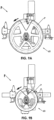
- the same facer F is seen in its assembled condition in Figure 9A with large diameter blade holders 60, as seen in Figure 3E , and in Figure 9B with small diameter blade holders 60, as seen in Figure 3G .
- the same drive unit 10 is used at its widest spacing of brackets in Figure 9A and at its narrowest spacing of brackets in Figure 9B .
- the same motor assembly 80 is used, but would be set at its lowest speed in Figure 9A and at its highest speed in Figure 9B .
- the facer F is seen in a horizontal orientation in Figures 9A and 9B and the blades 64 are angled for dispersing shaved ribbons S into the pipe P as seen in Figure 3C .
- the upper blade 64 would be angled for dispersing shaved ribbons S inside of the pipe P as seen in Figure 3C and the lower blade 64 would be angled for dispersing shaved ribbons S outside of the pipe P as seen in Figure 3D .
Abstract
Description
- This invention relates generally to machines used in the process of fusing polyolefin pipe and more particularly concerns facers used to prepare the opposed ends of two polyolefin pipes for butt fusion.
- Situations in which a facer might be of use in extending a polyolefin pipe in a tight working space, such as adjacent a wall or ceiling, are not uncommon. And accessibility to such a tight working space may be further complicated by the presence of other pipes, equipment and supporting structure in the vicinity. Unfortunately, however, known facers for polyolefin pipes of mid-range diameter are poorly designed for such applications. For example, the facer disclosed in
U.S. Patent No. 5,725,724 , must be fully assembled when mounted and dismounted from a fusion machine. - Most known mid-range diameter polyolefin pipe facers are simply too heavy to be lifted by hand into such tight working spaces. For example, facers for 60.96cm (24") OD polyolefin pipe typically weigh between 90.71kg (200) and 181.43kg (400 pounds).
- Many facers are designed to face a range of pipe sizes and so their output speeds (RPM) are selected to handle the largest diameter or thickest wall pipe in their pipe range. Consequently, when they are used to face a pipe with a smaller diameter or thinner wall, they operate slower than necessary and do not make full use of their available horsepower.
- Most known facers are designed to be mounted on carriages of only one size and their carriages are designed to be modified to permit the same facer to face a range of pipe sizes. Such facers must be sized for the largest pipe diameter in their range. Consequently, when used to face runs of smaller diameter pipe, the carriage size prevents the runs of pipe from being as close together as might otherwise be possible.
- And most known facers produce polyolefin ribbons that can wrap tightly around the ends of the opposed pipes during facer rotation. The ribbons can block the operator's view of the pipe ends and can build up sufficiently to require periodic stoppage of the facing process to clear the ribbons. Furthermore, the ribbons can fall into, tangle in and be hard to clean out of the fusion machine.
-
US3013925 discloses a facer drive unit a facer drive unit for mounting on the guide rails of a carriage of a machine used to fuse polyolefin pipe end-to-end, the facer drive unit comprising an elongated frame having two end portions and two guide rail brackets, one on each end portion of said frame. -
US2017/197255 discloses a facer for use in preparing the opposed ends of polyolefin pipes for fusion into a pipeline having a pair of cutting wheels which rotate in unison. A controller causes the cutting wheels to trace and face the pipe end walls in a closed loop path. The position of the brackets are adapted through two sliding means. -
FR1375963 - It is, therefore, an object of this invention to provide a polyolefin pipe facer that is of use in extending a polyolefin pipe in a tight working space. Another object of this invention is to provide a polyolefin pipe facer that reduces the impact of a facer's weight on its utility for use in a tight working space. A further object of this invention is to provide a polyolefin pipe facer that reduces the impact of a facer's size on its utility for use in a tight working space. It is also an object of this invention to provide a polyolefin pipe facer that affords greater accessibility to tight working spaces than known facers. Yet another object of this invention is to provide a polyolefin pipe facer that makes full use of its available horsepower for more than one size of pipe. An additional object of this invention is to provide a polyolefin pipe facer that enables the running of multiple sizes of pipe closer together than is possible with known facers. And it is an object of this invention to provide a polyolefin pipe facer that controls the dispersion of polyolefin ribbons produced by the facer.
- In accordance with the invention, a facer is provided that can be mounted on the guide rails of a fusion machine carriage and used to prepare polyolefin pipes for end fusion.
- The facer has a drive unit with guide rail brackets and an output shaft. The brackets are adapted for tool-free engagement preventing horizontal and vertical displacement of the drive unit relative to the guide rails. Two blade holders are adapted for tool-free engagement on and rotation with the output shaft of the drive unit with the blade holders in parallel and on opposite sides of the drive unit. A motor assembly is adapted for tool-free engagement preventing horizontal and vertical displacement of the motor assembly in relation to the drive unit. A linkage engages the output shafts of the drive unit and the motor assembly for transmission of power from the motor assembly output shaft to a drive unit output shaft. The linkage may be a mechanical coupling and may include a gearbox.
- The facer drive unit has a horizontal output shaft parallel to the guide rails. The free ends of the horizontal output shaft are on opposite sides of the drive unit and have penultimate portions of identical non-circular cross-section and ultimate portions with identical concentric circular adapters. Each blade holder has a center opening complementing the penultimate portion of a respective free end of the horizontal output shaft. Two latching assemblies, each surrounding its respective blade holder center opening, are operable to secure their respective blade holder to a respective one of the shaft concentric circular adapters with the center opening engaged on its respective shaft penultimate portion and with the two blade holders in parallel relationship. Preferably, each non-circular free end of the horizontal output shaft is hexagonal and each latching assembly is a split wedge clamp ring. The facer may have multiple pairs of blade holders of different diameters interchangeable with two blade holders. At least one blade is mounted on each blade holder at an angle selectable to cause ribbons of polyolefin shaved thereby to be dispensed either inside of or outside of their respective pipe.
- The drive unit module of the facer has an elongated frame and two guide rail brackets, one on each end portion of the frame. Two arrays of co-operable registries, each array corresponding to a respective one of the guide rail brackets, are configured to locate the guide rail brackets in any of multiple symmetrically spaced relationships from a center of the frame. Two indexing assemblies, one on each end portion of the frame, configured to secure the guide rail brackets in any of multiple symmetrically spaced relationships, are used to space the guide rail brackets in the spaced relationship closest to the distance between the guide rails. The guide rail brackets are U-shaped. A horizontal U-shaped bracket is engageable on one of the guide rails by lateral motion of the frame. A vertical U-shaped bracket is engageable on the other guide rail by downward motion of the vertical U-shaped bracket with the horizontal U-shaped bracket engaged on the one of the guide rails. A clamp mounted on the horizontal U-shaped bracket constrains facer motion in a vertical plane. A clamp mounted on the vertical U-shaped bracket constrains facer motion in a horizontal plane. A latch assembly mounted on the vertical U-shaped bracket retains the facer on the guide rails. Each array of co-operable registries has multiple apertures spaced longitudinally on the elongated frame and an aperture on its respective one of the guide rail brackets. Each index assembly is a spring pin. The linkage has an input shaft, an output shaft and a gearbox between the input and output shafts. Two adapters, one on each end of the linkage output shaft, enable tool-free engagement on and rotation with the linkage output shaft of a respective blade holder with the blade holders in parallel. A mounting socket is adapted for engagement with the frame of the drive motor assembly.
- Each blade holder module has a disk with a center opening for closely fitting a perimeter of a penultimate portion of the end of the drive unit module output shaft. A latching assembly surrounds the center opening and is operable to secure the disk to an ultimate portion of the end of the drive unit module output shaft with a disk perpendicular to the shaft. A blade is mounted on a distal face of the disk relative to the output shaft of the drive unit at either an angle causing ribbons of polyolefin shaved thereby to be dispensed inside of the pipe or an angle causing ribbons of polyolefin shaved thereby to be dispensed outside of the pipe. The disk has a recess in its distal face with two pairs of two holes in the recess registrable with two holes in the blade. Alignment of the two holes in the blade with one of the two pairs of holes in the disk causes the blade to be at the angle causing ribbons of polyolefin shaved thereby to be dispensed inside of the pipe. Alignment of the two holes in the blade with the of the two pairs of holes in the disk causes the blade to be at the angle causing ribbons of polyolefin shaved thereby to be dispensed outside of the pipe. The center opening is non-circular and preferably hexagonal. The latching assembly is preferably a split wedge clamp ring.
- The motor assembly module has a motor, a gearbox driven by the motor, an output shaft from the gearbox and a coupler on a free end of the output shaft. A connector has plug- and-socket components, one fixed to the motor assembly module and the other fixed to the frame of the drive unit module. The components have a configuration adapted for tool-free engagement preventing horizontal and vertical displacement of the motor assembly module in relation to drive unit module with the gearbox output shaft coupler engaged with the input shaft coupler for rotation with the gearbox output shaft. In this configuration, the couplers are spaced from their respective components so as to align the couplers on a common center axis of the drive unit input shaft and the gearbox output shaft. One component of the connector is adapted to telescope in the other component to engage the couplers. Apertures in the telescoping components are alignable to cooperate with a detent pin to secure them with the couplers engaged. The telescoping components are preferably vertically aligned tubular members of square cross-section. The gearbox is preferably a multi-speed gearbox operable at a speed selected to correspond to a cross-section of a pipe being faced.
- Other objects and advantages of the invention will become apparent upon reading the following detailed description and upon reference to the drawings in which:
-
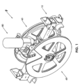
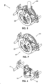
Figure 1 is a perspective view of a preferred embodiment of a facer in accordance with the invention for use in a process for end fusion of polyolefin pipe; -
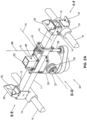
Figure 2A is an enlarged perspective view of a preferred embodiment of the drive unit of the facer ofFigure 1 ; -
Figure 2B is a top plan view illustrating a preferred embodiment of the gear assembly housed in the gearbox of the drive unit ofFigure 2A ; -
Figure 2C is a bottom plan view of the gear assembly ofFigure 2B ; -
Figure 2D is an elevation view of the gear assembly ofFigure 2B as seen in the direction D-D ofFigure 2A ; -
Figure 2E is an elevation view of the gear assembly ofFigure 2B as seen in the direction E-E ofFigure 2A ; -
Figure 2F is an elevation view of the gear assembly ofFigure 2B as seen in the direction F-F ofFigure 2A ; -
Figure 3A is an enlarged perspective view illustrating one cutting face of a preferred embodiment of the two blade holders of the facer ofFigure 1 with its blades in a "ribbon-inside" configuration; -
Figure 3B is an enlarged perspective view illustrating the other cutting face of the preferred embodiment of the two blade holders of the facer ofFigure 1 with its blades in a "ribbon-outside" configuration; -
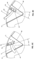
Figure 3C is an enlarged perspective view illustrating one cutting face of a preferred embodiment of the two blade holders of the facer ofFigure 1 with its blades in a "ribbon-inside" configuration; -
Figure 3D is an enlarged perspective view illustrating the other cutting face of the preferred embodiment of the two blade holders of the facer ofFigure 1 with its blades in a "ribbon-outside" configuration; -
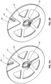
Figures 3E, 3F and 3G are perspective views illustrating large, medium and small blade holders, respectively, for use with the same drive unit according toFigure 2A ; -
Figure 4 is a perspective view of a preferred embodiment of the motor assembly of the facer ofFigure 1 ; -
Figure 5 is a perspective view of the three modules of the facer ofFigure 1 arranged for assembly into a facer according toFigure 1 ; -
Figure 6 is a perspective view of the drive unit seen inFigure 5 after mounting on the guide rails of a fusion machine carriage; -
Figure 7 is a perspective view of the blade holders seen inFigure 5 after mounting on the drive unit which is on the guide rails as seen inFigure 6 ; -
Figure 8 is a perspective view of the motor assembly seen inFigure 5 after mounting on the drive unit with the blade holders as seen inFigure 7 ; and -
Figures 9A and 9B are side elevation views illustrating the assembled facer ofFigure 8 using the large and small blade holders ofFigures 3E and 3G , respectively. - While the invention will be described in connection with preferred embodiments thereof, it will be understood that it is not intended to limit the invention to those embodiments or to the details of the construction or arrangement of parts illustrated in the accompanying drawings.
- Looking first at
Figure 1 , a modular facer F is adapted to be engaged on the guide rails R (seen inFigures 6-8 ) of a fusion machine carriage (not shown) for the purpose of facing the ends of polyolefin pipes P (seen inFigures 9A-9B ) for butt fusion. The term "polyolefin" identifies a most common application of the modular facer but is intended to include "nylon," PVC and other fusible non-polyolefin pipes. - The facer F is modular in the sense that it employs three types of modules including a
drive unit 10, twoblade holders 60 and amotor assembly 80 that are separable from one another. Eachmodule modules - This is made possible by use of a
drive unit 10, seen inFigures 1 and2A -2F, that is adjustable to accommodate different spacing between guide rails R of different fusion machines, by use ofblade holders 60, seen inFigures 1 and3A -3G, that are interchangeable to accommodate different diameters of pipe P and by use of amotor assembly 80, seen inFigures 1 and4 , that has multispeed capability to accommodate the total area of material to be faced, a total which varies in relation to the diameter and thickness of the pipe. - Turning to
Figure 2A , a preferred embodiment of thedrive unit 10 of the facer F is seen mounted on the guide rails R of a carriage of a machine used to fuse polyolefin pipe end-to-end. Anelongated frame 11 has twoguide rail brackets frame 11. Two sets ofregistries guide rail bracket respective brackets center axis 21 of theelongated frame 11. Looking atFigure 2A in the direction D-D, theleft hand registries right hand registries indexing assemblies 16, one on each end portion of theelongated frame 11, secure theirrespective brackets drive unit frame 11 can, for example, fit six different sizes of fusion machine carriages if the locations of theguide rail brackets registries 14 that are adjustable to six different carriage guide rail spacings. - The
elongated frame 11 as illustrated is fixed in overall length. Theguide rail brackets frame 11 stays the same. However, theframe 11 may be retractable within the space between theguide rail brackets - As seen in
Figure 2A , bothguide rail brackets horizontal bracket 12 is engageable on its respective guide rail R by lateral motion of theelongated frame 11 and thevertical bracket 13 is engageable on its respective guide rail R by downward motion of its respective end of theelongated frame 11 with thehorizontal bracket 12 engaged on its respective guide rail R. - Also as shown in
Figure 2A , each set ofregistries multiple apertures 14 spaced longitudinally on theelongated frame 11 and anaperture 15 on its respectiveguide rail bracket index assembly 16 is a spring pin that, when itsrespective bracket aperture 15 is aligned with a selected one of its respectivemultiple apertures 14 on theelongated frame 11, can be engaged in its respective alignedapertures brackets center axis 21 of theelongated frame 11. - After the horizontal
guide rail bracket 12 is registered and indexed on theframe 11, aclamp 17 mounted on thebracket 12 is tightened by use of aknob 18 to constrain facer motion in a vertical plane. After the verticalguide rail bracket 13 is registered and indexed on theframe 11, a clamp (not seen) mounted on thebracket 13 is tightened by use of a knob to constrain facer motion in a horizontal plane. The vertical bracket clamp is similar to thehorizontal bracket clamp 17 but in a 90° rotated orientation. - A
latch assembly 19 mounted on the verticalguide rail bracket 13 retains the facer F on the guide rails R. As best seen inFigures 9A and 9B , thelatch assembly 19 has a latch arm that pivots to cross under the guide rail R and engage a latch slot on the other side. A pull spring pin secures the arm in the latched or unlatched position. The horizontalguide rail bracket 12 cannot slide off its guide rail R as long as the verticalguide rail bracket 13 is on its guide rail R. - In the embodiment of
Figure 2A , a mountingsocket 22 on theelongated frame 11, as shown fixed on the top of theframe 11 in alignment with thecenter axis 21, is adapted for engagement with theframe 85 of themotor assembly 80, hereinafter discussed. And each of theguide rail brackets handle 23 to facilitate lifting and manipulating thedrive unit 10 into position on the guide rails R. - Also, as shown in
Figure 2A , thedrive unit 10 has alinkage 24 with aninput shaft 25 and anoutput shaft 26. Twoadapters 27 and 28, one on each end of thelinkage output shaft 26, enable tool-free engagement and rotation ofrespective blade holders 60 on and with thelinkage output shaft 26 with theblade holders 60 in parallel. Preferably, thelinkage 24 includes ahypoid gear 29 that convertsinput shaft 25 rotation about a vertical axis tooutput shaft 26 rotation about a horizontal axis. This enables themotor assembly 80 to be centered and balanced, rather than cantilevered and imbalanced, on theinput drive 10. - Looking at
Figures 1 and2A , a preferred embodiment of thedrive unit linkage 24 extends from itsinput coupler 31 through agearbox 32 to theadapters 27 on itsoutput shaft 26. As seen inFigures 2B-2F , thelinkage 24 is illustrated with the housing of thegearbox 32 removed. Thelinkage input shaft 25 rotates onball bearings 33 in unison with theinput coupler 31 on one of its ends and adrive sprocket 34 on its other end. Theinput coupler 31 is adapted to mate with anoutput shaft coupler 84 of themotor assembly 80 to transfer torque via theinput shaft 25 to thedrive sprocket 34. Thedrive sprocket 34 is engaged by aroller chain 35 to a drivensprocket 36 with itssprocket shaft 37 mounted on taperedroller bearings 38. In this embodiment, the "sprocket shaft" 37 is an extension of thepinion 39 and extends in parallel with the driveunit input shaft 25 to apinion 39 engaged with aring gear 41. Thering gear 41 andpinion 39 redirect the rotational motion of the input and drivesprocket shafts output shaft 26 of thedrive unit 10 about its horizontal axis. - Continuing to look at
Figures 2B-2F , theoutput shaft 26 of thedrive unit 10 extends at each end torespective adapters 27 and 28 configured for tool free connection to arespective blade holder 60. As shown, theblade holder adapters 27 have identical penultimatenoncircular portions 42 and identical ultimate concentricallycircular portions 43 cooperable for mating with components of itsrespective blade holder 60 hereinafter described. As shown, the penultimatenoncircular portion 42 of theadapters 27 are hex shaped. - Looking now at
Figures 1 and5 , twoblade holders 60 are mounted on thedrive unit 10 with theblade holders 60 parallel to each other and on opposite sides ofdrive unit 10. As shown, eachblade holder 60 is adisk 61 with acenter opening 62 for closely fitting a perimeter of an end of thefacer output shaft 26. Eachblade holder 60 has a latchingassembly 63 operable to secure thedisk 61 to an end of thefacer output shaft 26. - Turning to
Figures 3A-3B , eachblade holder 60 is preferably acircular disk 61 with acenter opening 62 complementing its respective penultimatenoncircular portion 42 of thehorizontal output shaft 26 of thedrive unit 10. Each bladeholder latching assembly 63 surrounds itscenter opening 62. The latchingassembly 63 is operated to secure itsblade holder 60 to the driveunit output shaft 26 after the center opening 62 of theblade holder 60 has been fully engaged on the penultimatenoncircular portion 42 of the driveunit output shaft 26. Preferably, and as seen inFigures 3A-3B , the latchingassembly 63 is a split wedge clamp ring adapted to grip the ultimate concentricallycircular portion 43 of the driveunit output shaft 26 that will extend through the latchingassembly 63 when theblade holder 60 is fully engaged on the penultimatenoncircular portion 42 of the driveunit output shaft 26. As shown, thenoncircular portions 42 of the driveunit output shaft 26 and thecenter openings 62 of theblade holder disk 61 are hexagonal. - Now looking at
Figures 3C-3D , eachblade holder 60 has at least oneblade 64 mounted on an outside face of thedisk 61. If, as seen inFigure 3C , the shavingedge 65 of theblade 64 is at anangle 66 in which its distal end leads its travel, shaved ribbons S of polyolefin will be dispensed inside of the pipe P being shaved. If, as seen inFigure 3D , the shavingedge 65 of theblade 64 is at anangle 67 in which its distal end trails its travel, shaved ribbons S of polyolefin will be dispensed outside of the pipe P being shaved. - As best seen in
Figures 3C-3D , ablade 64 is mounted in a V shapedrecess 68 in the outer face of thedisk 61. Therecess 68 has twosets blade 64. The alignment of the blade holes with oneset 69 of recess holes orients theblade 64 at theangle 66, causing shaved ribbons S of polyolefin to be dispensed inside of the pipe P. The alignment of the blade holes with theother set 71 of recess holes orients theblade 64 at theangle 67, causing shaved ribbons S of polyolefin to be dispensed outside of the pipe P. As shown, theblade 64 is secured in therecess 68 usingscrews 72.Multiple blades 64 can be mounted on adisk 61, preferably at equal angular displacements on thedisk 61, with eachblade 64 in aseparate recess 68. - The two
blade holders 60 are mirror images to provide proper orientation of the blades and position in their V shaped recesses 68. Eachblade holder 60 is mounted on its respective side of the facer F so that when rotating theblade edge 65 is leading and cutting and not trailing and dragging with theblade 64 on the trailing side of the V-shapedrecess 68. - For normal operation, the
blade 64 is oriented to disperse the shaved ribbons S inside the pipe P, as seen inFigure 3C . They remain inside the pipe P during the entire facing operation. As a result, the ribbons S do not tangle in the facer F or the fusion machine and do not wrap tightly around the pipe P. Therefore, it is not necessary to periodically stop facing to clear the shaved ribbons S. Furthermore, ribbons S do not wrap around the pipe P, so the operator's view of the pipe periphery is not blocked. After facing, cleanup is easily accomplished by pulling a bundle of ribbons S from each pipe end. - For fusion of vertically oriented pipe P, the
blade 64 is positioned as seen inFigure 3D so ribbons S drop outside of the pipe P and down and do not tangle in the facer F. Also, for fusion of vertically oriented pipe P, theblade 64 on thelower blade holder 60 can be angled to disperse shaved ribbons S outside of its respective pipe P and theblade 64 on the upper blade holder can be angled to disperse shaved ribbons S inside of its respective pipe P. - Moving on to
Figures 3E-3G , for thesame drive unit 10, pairs ofblade holders 60 of one diameter are interchangeable on theoutput shaft adapters 27 and 28 with pairs ofblade holders 60 of another diameter. For example,blade holders 60 of large, intermediate and smallouter diameter Figures 3E, 3F and 3G , respectively, but all have the samesize center openings 62 and latchingassemblies 63. Furthermore, the lengths of theblades 64 can be sufficient to accommodate different diameter pipes P. Pipes P are typically of standardized sequential diameters. If, for example, theblades 64 are each sufficiently long to accommodate two sequential diameters of pipe P and the large, intermediate and smallouter diameter blade holders 60 shown inFigures 3E, 3F and 3G , respectively, are available for use, thesame drive unit 10 can be used to face six different diameters of pipe P. - As seen in
Figures 3A-3G , the weight of ablade holder 60 can be reduced byvoids 76 through thedisk 61. However, if the shaved ribbons S are to be dispensed inside of the pipe P as by theblade holder 60 ofFigure 3C , it may necessary to close thevoids 76 in some applications. - Turning to
Figure 4 , themotor assembly 80 has amotor 81 with agearbox 82 driving anoutput shaft 83 with acoupler 84 on its free end. In the embodiment ofFigure 4 , a mountingframe 85 attached to themotor assembly 80 by abracket 86 has a mountingplug 87 adapted for engagement with thesocket 22 on theelongated frame 11 of thedrive unit 10, as shown inFigure 2A . Thecoupler 84 on the motorassembly output shaft 83 and theinput shaft coupler 31 of thedrive unit 10 are spaced from theplug 87 and thesocket 22 to align thecouplers common center axis 88. Thus, thecouplers motor assembly 80 is mounted on thedrive unit 10 by telescoping theplug 87 into thesocket 22. Adetent pin 89 inserted into alignedapertures 91 secures the telescopedplug 87 andsocket 22 with thecouplers - The plug and
socket components drive unit 10 andmotor assembly 80, respectively. In either configuration, thesocket 22 and plug 87 are adapted for tool-free engagement preventing horizontal and vertical displacement of themotor assembly 80 in relation to thedrive unit 10. Preferably, thetelescoping socket 22 and plug 87 are vertically aligned tubular members of square cross-section. - The
gearbox 82 is preferably a multi-speed gearbox operable at a speed selected to correspond to a cross-section of a pipe P being faced. A two-speed gearbox 82 can be set to low speed for larger and/or thicker pipe P and set to high speed for smaller and/or thinner pipe P. The horsepower required is governed in part by the speed of theblade 64, which is a function of RPM and pipe diameter, and wall thickness of the pipe P. The maximum required horsepower and blade holder RPM are governed by the largest and thickest pipe P. If the same RPM is used for smaller and thinner pipe, the blade speed will be slower and will not draw the full available horsepower. Using the high-speed setting for smaller/thinner pipe P reduces facing time. Alternatively, thedrive unit gearbox 32 may be adapted to provide the two-speed operation of the driveunit output shaft 26 using a singlespeed motor assembly 80. - A pair of
handles 92, each spaced from themotor 81 andgearbox 82 on acorresponding wing 93 of themotor assembly 80, extend onaxes 94 perpendicular to adiameter 95 of themotor 81 andgearbox 82 to facilitate lifting and manipulating themotor assembly 80 into position on thedrive unit 10. - Looking at
Figures 5 and6 , in assembling the facer F for use, thedrive unit 10 is first mounted on the carriage guide rails R. This is accomplished by lifting thedrive unit 10 above and squared with the carriage guide rails R, tilting thedrive unit 10 so that the horizontalguide rail bracket 12 points toward one guide rail R, sliding it onto that guide rail R until that guide rail R is fully seated in the horizontalguide rail bracket 12, rocking thedrive unit 10 on that guide rail R toward the other guide rail R until the verticalguide rail bracket 13 is fully seated on the other guide rail R and then swinging the vertical guiderail bracket latch 19 to its closed condition. - Looking at
Figures 5 and7 , with theblades 64 secured to theirrespective blade holders 60 at the desired angle for inside or outside dispersion of shaved ribbons S, the twoblade holders 60 can each be lifted up and attached one at a time to thedrive unit 10 by sliding them fully onto the hex nuts on the driveunit output shaft 26 and closing thelatching assemblies 63 on theblade holders 60. - Looking at
Figures 5 and8 , themotor assembly 80 is mounted on thedrive unit 10 by raising themotor assembly 80 above thedrive unit 10, aligning theplug 87 of themotor assembly 80 with thesocket 22 of thedrive unit 10 and lowering themotor assembly 80 to fully engage theplug 87 in thesocket 22, thereby simultaneously engaging thecoupler 84 of the motorassembly output shaft 83 with thecoupler 31 of the driveunit input shaft 25 and aligning theapertures 91 in theplug 87 and thesocket 22. Thedetent pin 89 can then be inserted into the alignedapertures 91, completing the assembly of the facer F. Disassembly of the facer F involves essentially a reversal of the steps of assembly. - The same facer F is seen in its assembled condition in
Figure 9A with largediameter blade holders 60, as seen inFigure 3E , and inFigure 9B with smalldiameter blade holders 60, as seen inFigure 3G . Thesame drive unit 10 is used at its widest spacing of brackets inFigure 9A and at its narrowest spacing of brackets inFigure 9B . Thesame motor assembly 80 is used, but would be set at its lowest speed inFigure 9A and at its highest speed inFigure 9B . The facer F is seen in a horizontal orientation inFigures 9A and 9B and theblades 64 are angled for dispersing shaved ribbons S into the pipe P as seen inFigure 3C . If the facer F were rotated 90° to a vertical orientation, theupper blade 64 would be angled for dispersing shaved ribbons S inside of the pipe P as seen inFigure 3C and thelower blade 64 would be angled for dispersing shaved ribbons S outside of the pipe P as seen inFigure 3D .
Claims (15)
- A facer for mounting on the guide rails (R) of a carriage of a machine used to fuse polyolefin pipe end-to-end, the facer comprising:a drive unit having guide rail brackets and an output shaft, wherein each of said guide rail brackets is adapted for tool-free engagement with a respective said guide rail to prevent horizontal and vertical displacement of said drive unit relative to the guide rails;two blade holders adapted for tool-free engagement on and rotation with said output shaft of said drive unit with said blade holders in parallel and on opposite sides of said drive unit;a motor assembly adapted for tool-free engagement with said drive unit to prevent horizontal and vertical displacement of said motor assembly in relation to said drive unit, said motor assembly having an output shaft; anda linkage engaging said output shafts of said drive unit and said motor assembly for transmission of power from said motor assembly output shaft to said drive unit output shaft.
- A facer according to claim 1, said linkage comprising a mechanical coupling.
- A facer according to claim 2, said linkage further comprising a gearbox.
- A facer according to claim 1, wherein the facer drive unit comprises:an elongated frame having two end portions;two guide rail brackets, one on each end portion of said frame;the facer drive unit having two arrays of co-operable registries, each said registry corresponding to a respective one of said guide rail brackets (R) and configured to locate said guide rail brackets in any of multiple symmetrically spaced relationships from a center of said frame; andtwo indexing assemblies, one on each end portion of said frame, respectively, securing said guide rail brackets in said any of multiple symmetrically spaced relationships at a spaced relationship closest to a distance between the guide rails.
- A facer according to claim 2, wherein said two guide rail brackets comprise:a U-shaped horizontal guide rail bracket engageable on one of the guide rails by lateral motion of said frame; anda U-shaped vertical guide rail bracket engageable on another of the guide rails by downward motion of said U-shaped vertical guide rail bracket with said U-shaped horizontal guide rail bracket engaged on said one of the guide rails.
- A facer according to claim 5, wherein said facer drive unit further comprises a clamp mounted on said U-shaped horizontal guide rail bracket to constrain facer motion in a vertical plane and a clamp mounted on said U-shaped vertical guide rail bracket to constrain facer motion in a horizontal plane.
- A facer according to claim 5, wherein said facer drive unit further comprises a latch assembly mounted on said U-shaped vertical guide rail bracket to retain the facer drive unit on the guide rails.
- A facer according to claim 4, wherein each of said two arrays of co-operable registries comprise:multiple apertures spaced longitudinally on said elongated frame; andan aperture on each of said guide rail brackets.
- A facer for mounting on the guide rails (R) of a carriage of a machine used to fuse polyolefin pipe end-to-end, the facer, the facer for shaving ribbons of polyolefin from a respective end of each respective end of each respective polyolefin pipe, the facer comprising:a drive unit having a horizontal output shaft parallel to the guide rails with free ends of said horizontal output shaft being on opposite sides of said drive unit, each said free end of said horizontal output shaft having a penultimate portion of non-circular cross-section and an ultimate portion with a circular adapter concentric with said horizontal output shaft, said penultimate portions being identical and said ultimate portions being identical;two blade holders, each said blade holder having a center opening complementing said penultimate portion of a respective said free end of said horizontal output shaft; andtwo latching assemblies, each surrounding said center opening of a respective said blade holder, each of said latching assemblies being operable to secure its respective said blade holder to a respective one of said circular adapters with said center opening of said respective blade holder engaged on a respective said penultimate portion and with said two blade holders in parallel relationship.
- A facer according to claim 9, each said latching assembly being a split wedge clamp ring.
- A facer according to claim 9, wherein said blade holders are respectively operable to shave the ribbons of polyolefin from the respective end of each respective polyolefin pipe, each said blade holder further comprising at least one blade mounted thereon at an angle causing ribbons of polyolefin shaved thereby to be dispensed inside or outside of their respective pipe.
- A facer according to claim 11, wherein the facer drive unit comprises:an elongated frame having two end portions;two guide rail brackets, one on each end portion of said frame;the facer drive unit having two arrays of co-operable registries, each said registry corresponding to a respective one of said guide rail brackets (R) and configured to locate said guide rail brackets in any of multiple symmetrically spaced relationships from a center of said frame; andtwo indexing assemblies, one on each end portion of said frame, respectively, securing said guide rail brackets in said any of multiple symmetrically spaced relationships at a spaced relationship closest to a distance between the guide rails.
- A facer according to claim 12, wherein said two guide rail brackets comprise:a U-shaped horizontal guide rail bracket engageable on one of the guide rails by lateral motion of said frame; anda U-shaped vertical guide rail bracket engageable on another of the guide rails by downward motion of said U-shaped vertical guide rail bracket with said U-shaped horizontal guide rail bracket engaged on said one of the guide rails.
- A facer according to claim 13, wherein said facer drive unit further comprises a clamp mounted on said U-shaped horizontal guide rail bracket to constrain facer motion in a vertical plane and a clamp mounted on said U-shaped vertical guide rail bracket to constrain facer motion in a horizontal plane.
- A facer according to claim 13, wherein said facer drive unit further comprises a latch assembly mounted on said U-shaped vertical guide rail bracket to retain the facer drive unit on the guide rails.
Applications Claiming Priority (4)
| Application Number | Priority Date | Filing Date | Title |
|---|---|---|---|
| US15/709,468 US10682780B2 (en) | 2017-09-19 | 2017-09-19 | Facer for end fusion of polyolefin pipes |
| PCT/US2018/050426 WO2019060176A1 (en) | 2017-09-19 | 2018-09-11 | Facer for end fusion of polyolefin pipes |
| EP21190708.4A EP3925762B1 (en) | 2017-09-19 | 2018-09-11 | Facer for end fusion of polyolefin pipes |
| EP18783602.8A EP3684598A1 (en) | 2017-09-19 | 2018-09-11 | Facer for end fusion of polyolefin pipes |
Related Parent Applications (2)
| Application Number | Title | Priority Date | Filing Date |
|---|---|---|---|
| EP18783602.8A Division EP3684598A1 (en) | 2017-09-19 | 2018-09-11 | Facer for end fusion of polyolefin pipes |
| EP21190708.4A Division EP3925762B1 (en) | 2017-09-19 | 2018-09-11 | Facer for end fusion of polyolefin pipes |
Publications (2)
| Publication Number | Publication Date |
|---|---|
| EP4257308A2 true EP4257308A2 (en) | 2023-10-11 |
| EP4257308A3 EP4257308A3 (en) | 2024-01-10 |
Family
ID=63799072
Family Applications (3)
| Application Number | Title | Priority Date | Filing Date |
|---|---|---|---|
| EP21190708.4A Active EP3925762B1 (en) | 2017-09-19 | 2018-09-11 | Facer for end fusion of polyolefin pipes |
| EP23193632.9A Pending EP4257308A3 (en) | 2017-09-19 | 2018-09-11 | Facer for end fusion of polyolefin pipes |
| EP18783602.8A Withdrawn EP3684598A1 (en) | 2017-09-19 | 2018-09-11 | Facer for end fusion of polyolefin pipes |
Family Applications Before (1)
| Application Number | Title | Priority Date | Filing Date |
|---|---|---|---|
| EP21190708.4A Active EP3925762B1 (en) | 2017-09-19 | 2018-09-11 | Facer for end fusion of polyolefin pipes |
Family Applications After (1)
| Application Number | Title | Priority Date | Filing Date |
|---|---|---|---|
| EP18783602.8A Withdrawn EP3684598A1 (en) | 2017-09-19 | 2018-09-11 | Facer for end fusion of polyolefin pipes |
Country Status (4)
| Country | Link |
|---|---|
| US (2) | US10682780B2 (en) |
| EP (3) | EP3925762B1 (en) |
| AU (2) | AU2018337624B2 (en) |
| WO (1) | WO2019060176A1 (en) |
Citations (4)
| Publication number | Priority date | Publication date | Assignee | Title |
|---|---|---|---|---|
| US3013925A (en) | 1959-04-03 | 1961-12-19 | Phillips Petroleum Co | Method and means for welding thermoplastic pipes |
| FR1375963A (en) | 1962-09-15 | 1964-10-23 | Forenade Plastfabriker Ab W & | Method for assembling thermoplastic pipes and device for this method |
| US5725724A (en) | 1996-01-08 | 1998-03-10 | Tdw Delaware, Inc. | Plastic pipe facer for butt fusion application |
| US20170197255A1 (en) | 2013-09-17 | 2017-07-13 | Mcelroy Manufacturing, Inc. | Cartesian Pipe Facer |
Family Cites Families (5)
| Publication number | Priority date | Publication date | Assignee | Title |
|---|---|---|---|---|
| US3552265A (en) * | 1968-11-01 | 1971-01-05 | Phillips Petroleum Co | Method and apparatus for facing thermoplastic pipe |
| US3729360A (en) * | 1971-03-08 | 1973-04-24 | A Mcelroy | Portable thermoplastic pipe fusion apparatus |
| US3793119A (en) * | 1972-01-04 | 1974-02-19 | W Province | Facing tool for plastic pipe fusion apparatus |
| ES2128792T3 (en) * | 1994-11-21 | 1999-05-16 | Omicron S R L | DEVICE AND PROCEDURE FOR THE BUTT WELDING OF PIPES OF THERMOPLASTIC MATERIAL. |
| US5814182A (en) * | 1997-09-19 | 1998-09-29 | Mcelroy Manufacturing, Inc. | Self-contained and self-propelled machine for heat fusing polyolefin pipes |
-
2017
- 2017-09-19 US US15/709,468 patent/US10682780B2/en active Active
-
2018
- 2018-09-11 EP EP21190708.4A patent/EP3925762B1/en active Active
- 2018-09-11 WO PCT/US2018/050426 patent/WO2019060176A1/en unknown
- 2018-09-11 EP EP23193632.9A patent/EP4257308A3/en active Pending
- 2018-09-11 EP EP18783602.8A patent/EP3684598A1/en not_active Withdrawn
- 2018-09-11 AU AU2018337624A patent/AU2018337624B2/en active Active
-
2020
- 2020-06-08 US US16/895,726 patent/US11034039B2/en active Active
-
2024
- 2024-02-06 AU AU2024200713A patent/AU2024200713A1/en active Pending
Patent Citations (4)
| Publication number | Priority date | Publication date | Assignee | Title |
|---|---|---|---|---|
| US3013925A (en) | 1959-04-03 | 1961-12-19 | Phillips Petroleum Co | Method and means for welding thermoplastic pipes |
| FR1375963A (en) | 1962-09-15 | 1964-10-23 | Forenade Plastfabriker Ab W & | Method for assembling thermoplastic pipes and device for this method |
| US5725724A (en) | 1996-01-08 | 1998-03-10 | Tdw Delaware, Inc. | Plastic pipe facer for butt fusion application |
| US20170197255A1 (en) | 2013-09-17 | 2017-07-13 | Mcelroy Manufacturing, Inc. | Cartesian Pipe Facer |
Also Published As
| Publication number | Publication date |
|---|---|
| EP3925762A2 (en) | 2021-12-22 |
| AU2018337624A1 (en) | 2020-03-12 |
| US10682780B2 (en) | 2020-06-16 |
| US11034039B2 (en) | 2021-06-15 |
| US20190084170A1 (en) | 2019-03-21 |
| WO2019060176A1 (en) | 2019-03-28 |
| EP4257308A3 (en) | 2024-01-10 |
| US20200338773A1 (en) | 2020-10-29 |
| AU2018337624B2 (en) | 2023-11-23 |
| EP3925762B1 (en) | 2023-08-30 |
| AU2024200713A1 (en) | 2024-02-22 |
| EP3925762A3 (en) | 2022-03-02 |
| EP3684598A1 (en) | 2020-07-29 |
Similar Documents
| Publication | Publication Date | Title |
|---|---|---|
| EP2241416B1 (en) | Robot with delta kinematics | |
| EP0576513A1 (en) | Multiaxis manipulator. | |
| US8065936B2 (en) | Offset pass through device | |
| EP1574310A2 (en) | A molded component retrieving apparatus and a molding machine having the molded component retrieving apparatus mounted thereon | |
| DE102018102644A1 (en) | Transfer tool | |
| EP3925762B1 (en) | Facer for end fusion of polyolefin pipes | |
| EP0355100B1 (en) | Industrial robot | |
| JP3917851B2 (en) | Welded joint cutting device for valve seat with valve box | |
| EP0281319A2 (en) | A rolling mill | |
| CN115609215B (en) | Welding device for large petrochemical equipment lifting appliance | |
| EP0613533A1 (en) | Maintenance friendly variable speed drive and methods | |
| CN111605216B (en) | Carbon fiber automobile part machining system and machining method | |
| US4412443A (en) | Roller forming machine with lengthwise adjustable heads | |
| CN220636779U (en) | Welding rotating frame | |
| CN218080543U (en) | Transmission shaft pilot hole processing frock | |
| CN212311369U (en) | Locking device and system for screw | |
| CN219649704U (en) | Sleeve machining clamping mechanism for optical fiber production | |
| CN218964527U (en) | Axle housing assembling, positioning and clamping device | |
| CN211516831U (en) | High security aluminum alloy ex-trusions cutting device | |
| CN213437378U (en) | Auxiliary tool rack for axial multi-hole drilling of pipe | |
| CN216543346U (en) | General tongs of bonnet | |
| CN219035037U (en) | Centrifugal compressor high-speed transmission gear shaft convenient to installation | |
| CN219383950U (en) | Multi-angle conversion catcher | |
| CN215468593U (en) | Tapping equipment | |
| CN117506306B (en) | Gear welding positioning clamp |
Legal Events
| Date | Code | Title | Description |
|---|---|---|---|
| PUAI | Public reference made under article 153(3) epc to a published international application that has entered the european phase |
Free format text: ORIGINAL CODE: 0009012 |
|
| STAA | Information on the status of an ep patent application or granted ep patent |
Free format text: STATUS: REQUEST FOR EXAMINATION WAS MADE |
|
| 17P | Request for examination filed |
Effective date: 20230828 |
|
| AC | Divisional application: reference to earlier application |
Ref document number: 3684598 Country of ref document: EP Kind code of ref document: P Ref document number: 3925762 Country of ref document: EP Kind code of ref document: P |
|
| AK | Designated contracting states |
Kind code of ref document: A2 Designated state(s): AL AT BE BG CH CY CZ DE DK EE ES FI FR GB GR HR HU IE IS IT LI LT LU LV MC MK MT NL NO PL PT RO RS SE SI SK SM TR |
|
| REG | Reference to a national code |
Ref country code: DE Ref legal event code: R079 Free format text: PREVIOUS MAIN CLASS: B26D0007060000 Ipc: B29C0065020000 |
|
| PUAL | Search report despatched |
Free format text: ORIGINAL CODE: 0009013 |
|
| AK | Designated contracting states |
Kind code of ref document: A3 Designated state(s): AL AT BE BG CH CY CZ DE DK EE ES FI FR GB GR HR HU IE IS IT LI LT LU LV MC MK MT NL NO PL PT RO RS SE SI SK SM TR |
|
| RIC1 | Information provided on ipc code assigned before grant |
Ipc: B29C 65/20 20060101ALN20231207BHEP Ipc: B26D 7/06 20060101ALI20231207BHEP Ipc: B26D 7/01 20060101ALI20231207BHEP Ipc: B26D 7/00 20060101ALI20231207BHEP Ipc: B26D 3/16 20060101ALI20231207BHEP Ipc: B26D 1/28 20060101ALI20231207BHEP Ipc: B23B 5/16 20060101ALI20231207BHEP Ipc: B23B 5/08 20060101ALI20231207BHEP Ipc: B29C 65/02 20060101AFI20231207BHEP |