EP4257301A1 - Functional safety system of robot - Google Patents
Functional safety system of robot Download PDFInfo
- Publication number
- EP4257301A1 EP4257301A1 EP21892363.9A EP21892363A EP4257301A1 EP 4257301 A1 EP4257301 A1 EP 4257301A1 EP 21892363 A EP21892363 A EP 21892363A EP 4257301 A1 EP4257301 A1 EP 4257301A1
- Authority
- EP
- European Patent Office
- Prior art keywords
- mobile robot
- duplexing
- safety zone
- sensor
- sensors
- Prior art date
- Legal status (The legal status is an assumption and is not a legal conclusion. Google has not performed a legal analysis and makes no representation as to the accuracy of the status listed.)
- Granted
Links
Images








Classifications
-
- B—PERFORMING OPERATIONS; TRANSPORTING
- B25—HAND TOOLS; PORTABLE POWER-DRIVEN TOOLS; MANIPULATORS
- B25J—MANIPULATORS; CHAMBERS PROVIDED WITH MANIPULATION DEVICES
- B25J9/00—Program-controlled manipulators
- B25J9/16—Program controls
- B25J9/1674—Program controls characterised by safety, monitoring, diagnostic
- B25J9/1676—Avoiding collision or forbidden zones
-
- G—PHYSICS
- G01—MEASURING; TESTING
- G01S—RADIO DIRECTION-FINDING; RADIO NAVIGATION; DETERMINING DISTANCE OR VELOCITY BY USE OF RADIO WAVES; LOCATING OR PRESENCE-DETECTING BY USE OF THE REFLECTION OR RERADIATION OF RADIO WAVES; ANALOGOUS ARRANGEMENTS USING OTHER WAVES
- G01S17/00—Systems using the reflection or reradiation of electromagnetic waves other than radio waves, e.g. lidar systems
- G01S17/88—Lidar systems specially adapted for specific applications
- G01S17/93—Lidar systems specially adapted for specific applications for anti-collision purposes
- G01S17/931—Lidar systems specially adapted for specific applications for anti-collision purposes of land vehicles
-
- B—PERFORMING OPERATIONS; TRANSPORTING
- B25—HAND TOOLS; PORTABLE POWER-DRIVEN TOOLS; MANIPULATORS
- B25J—MANIPULATORS; CHAMBERS PROVIDED WITH MANIPULATION DEVICES
- B25J11/00—Manipulators not otherwise provided for
- B25J11/008—Manipulators for service tasks
-
- B—PERFORMING OPERATIONS; TRANSPORTING
- B25—HAND TOOLS; PORTABLE POWER-DRIVEN TOOLS; MANIPULATORS
- B25J—MANIPULATORS; CHAMBERS PROVIDED WITH MANIPULATION DEVICES
- B25J13/00—Controls for manipulators
- B25J13/08—Controls for manipulators by means of sensing devices, e.g. viewing or touching devices
- B25J13/088—Controls for manipulators by means of sensing devices, e.g. viewing or touching devices with position, velocity or acceleration sensors
- B25J13/089—Determining the position of the robot with reference to its environment
-
- B—PERFORMING OPERATIONS; TRANSPORTING
- B25—HAND TOOLS; PORTABLE POWER-DRIVEN TOOLS; MANIPULATORS
- B25J—MANIPULATORS; CHAMBERS PROVIDED WITH MANIPULATION DEVICES
- B25J19/00—Accessories fitted to manipulators, e.g. for monitoring, for viewing; Safety devices combined with or specially adapted for use in connection with manipulators
- B25J19/02—Sensing devices
- B25J19/021—Optical sensing devices
- B25J19/022—Optical sensing devices using lasers
-
- B—PERFORMING OPERATIONS; TRANSPORTING
- B25—HAND TOOLS; PORTABLE POWER-DRIVEN TOOLS; MANIPULATORS
- B25J—MANIPULATORS; CHAMBERS PROVIDED WITH MANIPULATION DEVICES
- B25J9/00—Program-controlled manipulators
- B25J9/16—Program controls
- B25J9/1628—Program controls characterised by the control loop
- B25J9/1653—Program controls characterised by the control loop parameters identification, estimation, stiffness, accuracy, error analysis
-
- B—PERFORMING OPERATIONS; TRANSPORTING
- B25—HAND TOOLS; PORTABLE POWER-DRIVEN TOOLS; MANIPULATORS
- B25J—MANIPULATORS; CHAMBERS PROVIDED WITH MANIPULATION DEVICES
- B25J9/00—Program-controlled manipulators
- B25J9/16—Program controls
- B25J9/1656—Program controls characterised by programming, planning systems for manipulators
- B25J9/1664—Program controls characterised by programming, planning systems for manipulators characterised by motion, path, trajectory planning
- B25J9/1666—Avoiding collision or forbidden zones
-
- G—PHYSICS
- G05—CONTROLLING; REGULATING
- G05D—SYSTEMS FOR CONTROLLING OR REGULATING NON-ELECTRIC VARIABLES
- G05D1/00—Control of position, course, altitude or attitude of land, water, air or space vehicles, e.g. using automatic pilots
- G05D1/02—Control of position or course in two dimensions
- G05D1/021—Control of position or course in two dimensions specially adapted to land vehicles
- G05D1/0212—Control of position or course in two dimensions specially adapted to land vehicles with means for defining a desired trajectory
- G05D1/0214—Control of position or course in two dimensions specially adapted to land vehicles with means for defining a desired trajectory in accordance with safety or protection criteria, e.g. avoiding hazardous areas
-
- G—PHYSICS
- G05—CONTROLLING; REGULATING
- G05D—SYSTEMS FOR CONTROLLING OR REGULATING NON-ELECTRIC VARIABLES
- G05D1/00—Control of position, course, altitude or attitude of land, water, air or space vehicles, e.g. using automatic pilots
- G05D1/20—Control system inputs
- G05D1/24—Arrangements for determining position or orientation
- G05D1/242—Means based on the reflection of waves generated by the vehicle
- G05D1/2424—Means based on the reflection of waves generated by the vehicle for monitoring a plurality of zones
-
- G—PHYSICS
- G05—CONTROLLING; REGULATING
- G05D—SYSTEMS FOR CONTROLLING OR REGULATING NON-ELECTRIC VARIABLES
- G05D1/00—Control of position, course, altitude or attitude of land, water, air or space vehicles, e.g. using automatic pilots
- G05D1/60—Intended control result
- G05D1/617—Safety or protection, e.g. defining protection zones around obstacles or avoiding hazards
-
- G—PHYSICS
- G05—CONTROLLING; REGULATING
- G05D—SYSTEMS FOR CONTROLLING OR REGULATING NON-ELECTRIC VARIABLES
- G05D1/00—Control of position, course, altitude or attitude of land, water, air or space vehicles, e.g. using automatic pilots
- G05D1/60—Intended control result
- G05D1/617—Safety or protection, e.g. defining protection zones around obstacles or avoiding hazards
- G05D1/622—Obstacle avoidance
- G05D1/637—Obstacle avoidance using safety zones of adjustable size or shape
-
- G—PHYSICS
- G05—CONTROLLING; REGULATING
- G05B—CONTROL OR REGULATING SYSTEMS IN GENERAL; FUNCTIONAL ELEMENTS OF SUCH SYSTEMS; MONITORING OR TESTING ARRANGEMENTS FOR SUCH SYSTEMS OR ELEMENTS
- G05B2219/00—Program-control systems
- G05B2219/30—Nc systems
- G05B2219/39—Robotics, robotics to robotics hand
- G05B2219/39091—Avoid collision with moving obstacles
-
- G—PHYSICS
- G05—CONTROLLING; REGULATING
- G05B—CONTROL OR REGULATING SYSTEMS IN GENERAL; FUNCTIONAL ELEMENTS OF SUCH SYSTEMS; MONITORING OR TESTING ARRANGEMENTS FOR SUCH SYSTEMS OR ELEMENTS
- G05B2219/00—Program-control systems
- G05B2219/30—Nc systems
- G05B2219/40—Robotics, robotics mapping to robotics vision
- G05B2219/40476—Collision, planning for collision free path
-
- G—PHYSICS
- G05—CONTROLLING; REGULATING
- G05D—SYSTEMS FOR CONTROLLING OR REGULATING NON-ELECTRIC VARIABLES
- G05D2109/00—Types of controlled vehicles
- G05D2109/10—Land vehicles
-
- G—PHYSICS
- G05—CONTROLLING; REGULATING
- G05D—SYSTEMS FOR CONTROLLING OR REGULATING NON-ELECTRIC VARIABLES
- G05D2111/00—Details of signals used for control of position, course, altitude or attitude of land, water, air or space vehicles
- G05D2111/10—Optical signals
- G05D2111/17—Coherent light, e.g. laser signals
Definitions
- the present disclosure relates to a functional safety system of a robot, and more particularly, to an apparatus and a method for generating a dynamic safety zone of a mobile robot which generate a safety zone which is a zone to sense whether there is an obstacle.
- the present disclosure relates to a functional safety system of a robot, and more particularly, to a duplex system architecture modularizing apparatus and method of a mobile robot which duplex a module to satisfy a performance level d (pl-d) required by robot functional safety.
- the present disclosure relates to a functional safety system of a robot, and more particularly, to a sensor duplexing apparatus and method of a mobile robot which duplex a module to satisfy a performance level d (pl-d) required by robot functional safety.
- FIG. 1 is a view for explaining a method of generating a safety zone of the related art.
- a user When a dynamic safety zone of a robot is generated in the related art, a user receives and stores a shape of a static zone at every speed designated by a user and then if a speed reaches a corresponding speed, it is changed to a zone stored by the user to inspect whether there is an obstacle in the corresponding zone and stop. By doing this, the safety is ensured according to a number and shapes of zones according to a speed designated by the user . As a traveling direction of the robot is diversified, the number of zones according to the speed needs to be increased as many as the traveling directions so that a method of directly inputting the safety zone by the user has limitations according to the number of zones.
- Aperformance level d (PL-d) LiDAR which uses a dynamic safety zone limits a number of safety zones and a budget model may inputs up to six zones and a high-end model may input up to 32 zones.
- PL-d performance level d
- LiDAR light detection and ranging
- a robot using a mecanum wheel which requires various directions travels in both the x-axis and the y-axis and travels while rotating. Therefore, it is difficult for the user to designate an appropriate safety zone according to the speed and the direction for the dynamic driving.
- the speed is subdivided to increase the density between zones, the number of zones which need to be input by the user is also increased so that the larger the number of zones, the higher the risk due to the user fault. That is, as illustrated in FIG.
- the safety zone generating method of the related art in a state in which the user matches and stores the speed and the safety zone, when the corresponding condition is satisfied, the safety zone is changed so that the number of safety zones is limited.
- the higher the density between the safety zones the larger the number of safety zones and the higher the risk of the user fault by the user.
- FIG. 2 is a view for explaining a duplexing concept for a performance level d with category 3 required by a robot functional safety.
- the duplexing of the module at a performance level (pl) related to the functional safety is being demanded.
- the duplex system can be simply implemented using a LiDAR sensor certified for the performance level d (pl-d).
- the LiDAR sensor certified for the performance level d (pl-d) is expensive so that there is a problem in that it takes a lot of money to implement the duplex system.
- only a function provided by a manufacturer that manufactures the corresponding LiDAR sensor can be used so that it is difficult to flexibly implement a function.
- three module terminals including a input terminal I, a logic terminal L, and an output terminal O need to be duplexed.
- the input terminal is duplexed to a "LiDAR sensor A (I1)” and a LiDAR sensor B (I2) "
- the logic terminal is duplexed to a "LiDAR logic board A (L1) “ and a “LiDAR logic board B (L2) “
- the output terminal is duplexed to "01” and "02" and stops when the result is "0" or "2".
- An object to be achieved by the present disclosure is to provide an apparatus and a method for generating a dynamic safety zone of a mobile robot which variably generate a safety zone required for a functional safety of a mobile robot according to an appearance and a speed of the mobile robot.
- An object to be achieved by the present disclosure is to provide an apparatus and a method for modularizing a duplex system architecture of a mobile robot which duplex the entire system architecture to satisfy a performance level d (pl-d) demanded by the functional system of a robot.
- An object to be achieved by the present disclosure is to provide an apparatus and a method for modularizing a duplex system architecture of a mobile robot which duplex a sensor using obstacle information detected by a sensor to satisfy a performance level d (pl-d) demanded by the functional system of a robot.
- a dynamic safety zone generating apparatus of a mobile robot includes an information acquiring unit which acquires a movement direction and a movement speed of a mobile robot; and a safety zone generating unit which dynamically generates a safety zone for the mobile robot based onatleast one of shape information of the mobile robot, a movement direction of the mobile robot acquired by the information acquiring unit, and a movement speed of the mobile robot acquired by the information acquiring unit.
- the safety zone generating unit acquires a future predicted position of the mobile robot based on the movement direction and the movement speed of the mobile robot and dynamically generates a safety zone of the mobile robot based on the shape information of the mobile robot and the future predicted location of the mobile robot.
- the dynamic safety zone generating unit acquires the movement speed of the x-axis direction and the movement speed of the y-axis direction based on the movement direction and the movement speed of the mobile robot, acquires the future predicted x-axis location based on the movement speed of the x-axis direction and acquires the future predicted y-axis location of the mobile robot based on the movement speed of the y-axis direction, and acquires a future predicted location of the mobile robot based on the future predicted x-axis location and the future predicted y-axis location.
- the safety zone generating unit acquires a default safety zone based on the shape information of the mobile robot and dynamically generates a safety zone for the mobile robot based on the default safety zone and the future predicted location of the mobile robot.
- the safety zone generating unit acquires front, rear, left, and right distances with respect to the center point of the mobile robot based on the shape information of the mobile robot and acquires a default safety zone formed of four vertices based on the center point of the robot and the front, rear, left, and right distances.
- the safety zone generating unit 130 varies the front, rear, left, and right distances according to the default safety zone based on the future predicted location of the mobile robot to dynamically generate the safety zone for the mobile robot.
- the safety zone generating unit acquires a plurality of sub safety zones by varying the front, rear, left, and right distances according to the default safety zone plural times, based on the current location of the mobile robot and the future predicted location of the mobile robot and dynamically generates the safety zone for the mobile robot based on the plurality of sub safety zones.
- a sensor duplexing apparatus of a mobile robot an input unit in which a plurality of sensors is mounted; a logic unit in which a plurality of logic boards corresponding to the plurality of sensors mounted in the input unit is mounted; an output unit which transmits an output value to the outside based on the output of the plurality of logic boards mounted in the logic unit; and a controller which duplexes the sensor in the unit of predetermined duplexing areas based on obstacle information detected by each of the plurality of sensors.
- the controller duplexes two sensors based on obstacle information detected by two sensors corresponding to the duplexing area.
- the controller determines that duplexing of two sensors is successful and when obstacle information detected by two sensors corresponding to the duplexing area do not match, the controller determines that duplexing of two sensors has failed.
- the controller identifies whether the obstacle information detected by two sensors corresponding to the duplexing area match using predetermined sensor error information.
- the controller duplexes two sensors using obstacle information detected by two sensors based on the dynamic safety zone generated by two sensors corresponding to the duplexing area.
- a duplex system architecture modularizing apparatus of a mobile robot includes an input unit in which a plurality of sensors is mounted; a logic unit in which a plurality of logic boards corresponding to the plurality of sensors mounted in the input unit is mounted; an output unit which transmits an output value to the outside using a duplexing parameter based on the output of the plurality of logic boards mounted in the logic unit; and a controller which changes a value of the duplexing parameter including logic board identification information, logic board type information, and sensor location information based on duplexing target information input by a user.
- an expected location of a mobile robot can be calculated according to a speed/direction by shape information and direction/speed information of a mobile robot without inputting the safety zone by the user and a dynamic safety zone is automatically generated to be used for all mobile robots mounted with various wheels, such as a diff wheel or a Mecanum wheel.
- the safety zones are automatically generated in all directions without directly inputting the safety zone by the user so that the safety function for the density between the safety zones and omni-directions can be performed and the user fault caused by the user input may be significantly reduced.
- the apparatus and the method for modularizing a duplex system architecture of a mobile robot in order to satisfy the performance level d (pl-d) demanded by the functional safety of the robot, the entire system architecture is duplexed to remove a sensor or add a new sensor without changing the entire system architecture.
- the senor in order to satisfy the performance level d (pl-d) demanded by the functional safety of the robot, the sensor is duplexed using obstacle information detected by the sensor so that a duplex system may be implemented using a cheap general LiDAR sensor which is not certified for pl-d.
- first or second are used to distinguish one component from the other component so that the scope should not be limited by these terms .
- a first component may be referred to as a second component, and similarly, a second component may be referred to as a first component.
- the terms “have”, “may have”, “include”, or “may include” represent the presence of the characteristic (for example, a numerical value, a function, an operation, or a component such as a part"), but do not exclude the presence of additional characteristic.
- ⁇ unit used in the specification refers to a software or hardware component such as a field programmable gate array (FPGA) or an ASIC and "-unit” performs some functions.
- ⁇ unit is not limited to the software or the hardware.
- " ⁇ unit” may be configured to be in an addressable storage medium or may be configured to reproduce one or more processors.
- “-unit” includes components such as software components, object oriented software components, class components, and task components, processes, functions, attributes, procedures, subroutines, segments of a program code, drivers, a firmware, a microcode, a circuit, data, database, and data structures.
- a function which is provided in the components and " ⁇ units” may be combined with a smaller number of components and “ ⁇ units” or divided into additional components and “ ⁇ units”.
- the functional safety system of a robot dynamically generates a safety zone and duplexes a system module and a LiDAR sensor for a performance level d (pl-d).
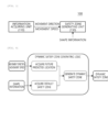
- FIG. 3 is a block diagram for explaining an apparatus of generating a dynamic safety zone of a mobile robot according to a first exemplary embodiment of the present disclosure
- FIG. 4 is a view for explaining a process of generating a dynamic safety zone according to a first exemplary embodiment of the present disclosure
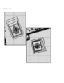
- FIG. 5 is a view for explaining an operation of acquiring a default safety zone according to a first exemplary embodiment of the present disclosure
- FIG. 6 is a view for explaining an operation of acquiring a future predicted location according to a first exemplary embodiment of the present disclosure
- FIG. 7 is a view for explaining an operation of generating a dynamic safety zone according to a first exemplary embodiment of the present disclosure.
- an apparatus 100 for generating a dynamic safety zone of a mobile robot according to a first exemplary embodiment of the present disclosure variably generates a safety zone required for the functional safety of the mobile robot according to an appearance and a speed of the mobile robot.
- the present disclosure is applicable to household cleaning robots, public building cleaning robots, logistics robots, service robots, as well as industrial robots. That is, the dynamic safety zone generating apparatus 100 according to the present disclosure is free from a method having a limitation for a number of safety zones and a high risk of a user fault due to a method of directly inputting a safety zone by a user according to a speed and a direction of the mobile robot, which is a method according to a related art, and calculates a predicted location of a mobile robot according to a speed/direction by shape information and direction/speed information of the mobile robot without inputting a safety zone by a user and automatically generates a dynamic safety zone to be used for all mobile robots mounted with various wheels such as a diff wheel and a Mecanum wheel.
- the safety zone is automatically generated for all directions without directly inputting the safety zone by a user so that the safety function for the density between the safety zones and omni-directions may be performed and a user fault by the user input may be significantly reduced.
- the dynamic safety zone generating apparatus 100 is loaded in a mobile robot to dynamically generate a safety zone based on information acquired from the sensor mounted in the mobile robot.
- the dynamic safety zone generating apparatus 100 according to the present disclosure is loaded in a server which remotely manages the mobile robot by wireless communication to dynamically generate the safety zone of the mobile robot based on the information provided from the mobile robot and provide information about the generated safety zone to the mobile robot.
- the dynamic safety zone generating apparatus 100 includes an information acquiring unit 110 and a safety zone generating unit 130.
- the information generating unit 110 acquires a movement direction and a movement speed of the mobile robot.
- the movement direction of the mobile robot refers to one of a traveling direction according to a straight movement of the mobile robot, a traveling direction according to the rotation of the mobile robot, and a traveling direction when the rotational movement and the straight movement of the mobile robot are simultaneously generated.
- the straight movement of the mobile robot refers to one of a straight movement on the x-axis, a straight movement on the y-axis, and a diagonal movement on the x-axis and the y-axis.
- the rotation of the mobile robot refers to one of the rotational movement to the left side and the rotational movement to the right side.
- the safety zone generating unit 130 dynamically generates a safety zone for the mobile robot based on at least one of shape information of the mobile robot, a movement direction of the mobile robot acquired by the information acquiring unit 110, and a movement speed of the mobile robot acquired by the information acquiring unit 110.
- the safety zone generating unit 130 dynamically generates the safety zone for the mobile robot in the unit of predetermined cycles.
- the safety zone generating unit 130 dynamically generates the safety zone of the mobile robot when at least one of the movement direction and the movement speed of the mobile changes.
- the safety zone generating unit 130 acquires a future predicted position of the mobile robot based on the movement direction and the movement speed of the mobile robot. For example, as illustrated in FIG. 6 , the safety zone generating unit 130 may acquire a future location of the mobile robot to be predicted with respect a current center location of the mobile robot, based on the movement direction and the movement speed of the mobile robot.
- the safety zone generating unit 130 may acquire the movement speed of the x-axis direction and the movement speed of the y-axis direction based on the movement direction and the movement speed of the mobile robot.
- the safety zone generating unit 130 may acquire a future predicted x-axis location of the mobile robot based on the movement speed of the x-axis direction and a future predicted y-axis location of the mobile robot based on the movement speed of the y-axis direction.
- the safety zone generating unit 130 acquires the future predicted location of the mobile robot based on the future predicted x-axis location and the future predicted y-axis location.
- the safety zone generating unit 130 acquires the future predicted location of the mobile robot by means of the following Equation 1.
- future location . x speed . x * response time + braking distance + margin distance future location .
- y speed . y * response time + braking distance + margin distance
- future location.x indicates the future predicted x-axis location and future location.y indicates the future predicted y-axis location.
- speed.x indicates a movement speed of the x-axis direction of the mobile robot and speed, y indicates a movement speed of the y-axis direction of the mobile robot.
- braking distance indicates a distance required to stop the mobile robot and is set in advance according to the speed of the mobile robot.
- margin distance indicates a margin distance which is set in advance for the safety of the mobile robot.
- sensor scanning time indicates a scanning time of the sensor mounted in the mobile robot.
- sampling count indicates a number of samplings of the sensor mounted in the mobile robot.
- communication delay indicates a communication delay time of the sensor mounted in the mobile robot.
- margin response time indicates a margin response time which is set in advance for exact measurement of the sensor mounted in the mobile robot.
- the safety zone generating unit 130 may dynamically generate a safety zone for the mobile robot based on the shape information of the mobile robot and the future predicted location of the mobile robot.
- the shape information of the mobile robot refers to information about the appearance of the robot.
- the safety zone generating unit 130 may acquire a default safety zone based on the shape information of the mobile robot and dynamically generate a safety zone for the mobile robot based on the default safety zone and the future predicted location of the mobile robot.
- the safety zone generating unit 130 acquires front, rear, left, and right distances with respect to the center point of the mobile robot based on the shape information of the mobile robot and acquires a default safety zone formed of four vertices based on the center point of the robot and the front, rear, left, and right distances. For example, as illustrated in FIG. 5 , the safety zone generating unit 130 acquires a first distance (a front side distance), a second distance (a rear side distance), a third distance (a left side distance), and a fourth distance (a right side distance) with respect to the center point of the mobile robot and acquires a default safety zone based on the acquired first to fourth distances.
- speed indicates a movement speed of the mobile robot.
- response time is a response time of a sensor mounted in the mobile robot and is acquired by the above Equation 2.
- braking distance indicates a distance required to stop the mobile robot and is set in advance according to the speed of the mobile robot.
- margin distance indicates a margin distance which is set in advance for the safety of the mobile robot.
- the safety zone generating unit 130 acquires a plurality of sub safety zones by varying the front, rear, left, and right distances according to the default safety zone plural times, based on the current location of the mobile robot and the future predicted location of the mobile robot and dynamically generates the safety zone for the mobile robot based on the plurality of sub safety zones.
- the safety zone generating unit 130 acquires a sub safety zone in every predetermined distance unit, by dividing a path along which the mobile robot moves from a start point to a target time into a predetermined distance unit with the current location of the mobile robot as the start point and the future predicted location of the mobile robot as the target point and dynamically generates the safety zone for the mobile robot by overlapping the plurality of acquired sub safety zones.
- FIG. 8 is a view for explaining an example of generating a dynamic safety zone according to a first exemplary embodiment of the present disclosure to illustrate a straight movement on one axis
- FIG. 9 is a view for explaining an operation of generating a dynamic safety zone for diagonal movement according to a first exemplary embodiment of the present disclosure
- FIG. 10 is a view for explaining an example of generating a dynamic safety zone according to a first exemplary embodiment of the present disclosure to illustrate a diagonal movement on an x-axis and a y-axis
- FIG. 11 is a view for explaining an operation of generating a dynamic safety zone of rotational movement according to a first exemplary embodiment of the present disclosure
- FIG. 11 is a view for explaining an operation of generating a dynamic safety zone of rotational movement according to a first exemplary embodiment of the present disclosure
- FIG. 12 is a view for explaining an example of generating a dynamic safety zone according to a first exemplary embodiment of the present disclosure to illustrate a rotational movement
- FIG. 13 is a view for explaining an example of generating a dynamic safety zone according to a first exemplary embodiment of the present disclosure to illustrate a case in which a rotational movement and a straight movement simultaneously occur.
- the faster the speed the longer the length of the safety zone which is dynamically generated and the slower the speed, the smaller the safety zone.
- the safety zone which is dynamically generated should not be smaller than the shape of the mobile robot, that is, the default safety zone.
- the mobile robot when the mobile robot simultaneously moves to the x-axis and the y-axis, the mobile robot diagonally travels and the safety zone is dynamically and automatically generated so that the mobile robot does not collide with the obstacle during the diagonal traveling.
- a shape of the safety zone which is dynamically generated according to the rotation direction of the mobile robot is changed so that when the mobile robot rotates to the right side, a upper right end and an upper left end which are likely to collide become longer and when the mobile robot rotates to the left side, the upper left end and the lower right end may become longer.
- a safety zone in which a rotational value is added based on a value obtained from the future predicted location of the mobile robot is generated and all the safety zones are automatically determined and changed according to the speed and the direction.
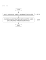
- FIG. 14 is a flowchart for explaining a method for generating a dynamic safety zone of a mobile robot according to a first exemplary embodiment of the present disclosure.
- the dynamic safety zone generating apparatus 100 acquires a movement direction and a movement speed of the mobile robot (S110).
- the dynamic safety zone generating apparatus 100 dynamically generates the safety zone for the mobile robot based on at least one of the shape information of the mobile robot, the movement direction of the mobile robot, and the movement speed of the mobile robot (S130).
- the dynamic safety zone generating apparatus 100 dynamically generates the safety zone for the mobile robot in the unit of predetermined cycles.
- the dynamic safety zone generating apparatus 100 dynamically generates the safety zone of the mobile robot when at least one of the movement direction and the movement speed of the mobile changes.
- the dynamic safety zone generating apparatus 100 acquires a future predicted location of the mobile robot based on the movement direction and the movement speed of the mobile robot. That is, the dynamic safety zone generating apparatus 100 acquires the movement speed of the x-axis direction and the movement speed of the y-axis direction based on the movement direction and the movement speed of the mobile robot, acquires the future predicted x-axis location of the mobile robot based on the movement speed of the x-axis direction and acquires the future predicted y-axis location of the mobile robot based on the movement speed of the y-axis direction, and acquires a future predicted location of the mobile robot based on the future predicted x-axis location and the future predicted y-axis location.
- the dynamic safety zone generating apparatus 100 may dynamically generate a safety zone for the mobile robot based on the shape information of the mobile robot and the future predicted location of the mobile robot.
- the dynamic safety zone generating apparatus 100 may acquire a default safety zone based on the shape information of the mobile robot and dynamically generate a safety zone for the mobile robot based on the default safety zone and the future predicted location of the mobile robot. At this time, the dynamic safety zone generating apparatus 100 acquires front, rear, left, and right distances with respect to the center point of the mobile robot based on the shape information of the mobile robot and acquires a default safety zone formed of four vertices based on the center point of the robot and the front, rear, left, and right distances.
- the dynamic safety zone generating apparatus 100 varies the front, rear, left, and right distances according to the default safety zone based on the future predicted location of the mobile robot to dynamically generate the safety zone for the mobile robot.
- the dynamic safety zone generating apparatus 100 acquires a plurality of sub safety zones by varying the front, rear, left, and right distances according to the default safety zone plural times, based on the current location of the mobile robot and the future predicted location of the mobile robot and dynamically generates the safety zone for the mobile robot based on the plurality of sub safety zones.
- FIGS. 15 to 18 An apparatus and a method for modularizing a duplex system architecture of a mobile robot which is a second exemplary embodiment of a functional safety system of a robot according to the present disclosure will be described in detail with reference to FIGS. 15 to 18 .
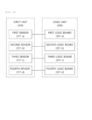
- FIG. 15 is a block diagram for explaining an apparatus for modularizing a duplex system architecture of a mobile robot according to a second exemplary embodiment of the present disclosure.
- the apparatus 200 for modularizing a duplex system architecture of a mobile robot may duplex the entire system architecture to satisfy the pl-d (performance level d) requested by the robot functional safety.
- the present disclosure is applicable to household cleaning robots, public building cleaning robots, logistics robots, service robots, as well as industrial robots.
- three module terminals including a input terminal I, a logic terminal L, and an output terminal O need to be duplexed.
- the input terminal is duplexed to a "LiDAR sensor A (I1)” and a LiDAR sensor B(I2)”
- the logic terminal is duplexed to a "LiDAR logic board A (L1)” and a “LiDAR logic board B (L2) "
- the output terminal is duplexed to "01” and "02” and stops when the result is "0" or "2”.
- the present disclosure relates to a method for performing the duplexing in view of the entire system architecture.
- the modularizing apparatus 200 includes an input unit 210, a logic unit 230, an output unit 250, and a controller 270.
- a plurality of sensors 211 may be mounted in the input unit 210.
- the senor 211 may be one of a LiDAR sensor, an encoder sensor, and a cliff sensor.
- a plurality of logic boards 231 corresponding to the plurality of sensors 211 mounted in the input unit 210 may be mounted.
- the logic board 231 may be one of a LiDAR board, an encoder board, and the other (ETC) board.
- the output unit 250 transmits an output value to the outside using a duplexing parameter based on outputs of the plurality of logic boards 231 mounted in the logic unit 230.
- the controller 270 may change a value of the duplexing parameter based on duplexing target information input by the user.
- the duplexing parameter includes logic board identification information which is unique information to identify the logic board 231, logic board type information which is information to identify a type of the logic board 231, and sensor location information which is information to identify the location of the sensor 211.
- duplex system architecture modularizing apparatus of a mobile robot according to a second embodiment of the present disclosure will be described in more detail with reference to FIG. 16 .
- FIG. 16 is a block diagram for explaining a sub configuration of a duplex system architecture modularizing apparatus illustrated in FIG. 15 .
- a plurality of “type A” sensors A 211-a is mounted, a plurality of “type B” sensors B 211-b is mounted, and a plurality of “type C” sensors C 211-c is mounted.
- the "type A” refers to the LiDAR sensor
- the “type B” refers to an Encoder sensor
- the “type C” refers to the Cliff sensor.
- the logic unit 230 of the modularizing apparatus 200 includes a plurality of "type A” logic boards A 231-a mounted corresponding to the plurality of sensors A211-a mounted in the input unit 210, a plurality of "type B” logic boards B 231-b mounted corresponding to the plurality of sensors B 211-b mounted in the input unit 210, and a plurality of "type C” logic boards C 231-c mounted corresponding to the plurality of sensors C 211-c mounted in the input unit 210.
- the "type A” refers to the LiDAR board
- the "type B” refers to an Encoder board
- the "type C” refers to the Cliff board.
- the plurality of logic boards 231 mounted in the logic unit 230 that is, the plurality of logic boards A 231-a, the plurality of logic boards B 231-b, and the plurality of logic boards C 231-c are connected to one communication network.
- the controller 270 of the modularizing apparatus 200 changes the value of the duplexing parameter in the unit of the duplexing target set based on the duplexing target information.
- the duplexing target information includes logic board identification information of a duplexing target and sensor information corresponding to the logic board of the duplexing target.
- the controller 270 may change the value of the duplexing parameter including a first pair of logic board identification information, a first pair of logic board type information, a first pair of sensor location information, a second pair of logic board identification information, a second pair of logic board type information, and a second pair of sensor location information in the unit of duplexing target sets to dynamically changes the duplexing target.
- the output unit 250 includes two OR gates 251 and 252 and sets inputs for two OR gates 251 and 252 using the duplexing parameter based on the output of the plurality of logic boards 231 and transmits the output values of two OR gates 251 and 252.
- the controller 270 controls the output unit 250 based on the duplexing target information to set the output of the logic board corresponding to the first pair of duplexing target sets to be input to the first OR gate and to set the output of the logic board corresponding to the second pair of duplexing target sets to be input to the second OR gate.
- the sensors A 211-a which are two LiDAR sensors, the sensors B 211-b which are two Encoder sensors, and the sensors C 211-c which are two Cliff sensors are installed in the input unit 210 and the logic board A 231-a which are two LiDAR boards corresponding to two sensors A 211-a, the logic board B 231-b which are two Encoder boards corresponding to two sensors B 231-b, and the logic boards C 231-c which are two ETC boards corresponding to two sensors C 211-c are installed, and then the duplexing target information as follows may be input.
- the controller 270 of the modularizing apparatus 200 changes the value of the duplexing parameter in the unit of duplexing target set as follows, based on the above duplexing target information to dynamically change the duplexing target.
- the controller 270 may set to input one logic board A 231-a between two logic boards A 231-a set as the first pair, one logic board B 231-b between two logic boards A 231-b set as the first pair, and one logic board C 231-c between two logic boards C 231-c set as the first pair to the first OR gate 251. Further, the controller 270 may set to input one logic board A 231-a between two logic boards A 231-a set as the second pair, one logic board B 231-b between two logic boards A 231-b set as the second pair, and one logic board C 231-c between two logic boards C 231-c set as the second pair to the second OR gate 252.
- the output terminal may be duplexed.
- FIG. 17 is a view for explaining an implementation example of a duplex system architecture modularizing apparatus of a mobile robot according to a second exemplary embodiment of the present disclosure.
- the entire system is configured by dividing an input terminal I, a logic terminal L, and an output terminal O and each logic board LB 231 is formed by one communication network to remove or add a module to the logic board LB 231 in accordance with the number of sensors 211 required for duplexing.
- two OR gates 251 and 252 are configured so that even though the module of the logic board LB 231 is removed or newly added, the duplex system may be implemented without changing the entire system architecture.
- the logic board LB 231 is configured for every sensor 211 to configure a duplex system in the unit of modules and the output terminal is duplexed using the output board (two OR gates) which are duplexed regardless of the number of output data from the entire logic terminals so that the pl-d architecture is possible without causing a big change of the entire duplex system architecture whenever the number of sensors 211 changes.
- the logic terminal is largely divided into three types: a LiDAR board, an encoder board, and an ETC board.
- the number of LiDAR sensors dynamically changes to two to four
- the number of Encoder sensors dynamically changes to two to four
- the number of Cliff sensors dynamically changes to four to eight.
- the number of sensors 211 may change without separately changing the software in the board and the user may transmit the changed content to the corresponding board as data of the parameter. That is, the user may transmit the changed content to the corresponding board by inputting the duplexing target information.
- the corresponding board When the user inputs the duplexing target information such as an ID number of the logic board 231 to be duplexed and the number of sensors 211, the corresponding board automatically changes a value of the following duplexing parameter based on the duplexing target information through an internal algorithm.
- the target to be duplexed may be dynamically changed by the duplexing parameter as described above. That is, according to the present disclosure, after changing the number of sensors to be changed in the unit of systems, when only the value of the duplexing parameter is changed in accordance therewith, the duplexing target is automatically changed.
- FIG. 18 is a flowchart for explaining a method for modularizing a duplex system architecture of a mobile robot according to a second exemplary embodiment of the present disclosure.
- the modularizing apparatus 200 inputs duplexing target information by a user (S210).
- the duplexing target information includes logic board identification information of a duplexing target and sensor information corresponding to the logic board of the duplexing target.
- the modularizing apparatus 200 changes the value of the duplexing parameter based on the duplexing target information (S230).
- the duplexing parameter includes logic board identification information which is unique information to identify the logic board 231, logic board type information which is information to identify a type of the logic board 231, and sensor location information which is information to identify the location of the sensor 211.
- the modularizing apparatus 200 changes the value of the duplexing parameter in the unit of the duplexing target set based on the duplexing target information.
- the modularizing apparatus 200 may change the value of the duplexing parameter including a first pair of logic board identification information, a first pair of logic board type information, a first pair of sensor location information, a second pair of logic board identification information, a second pair of logic board type information, and a second pair of sensor location information in the unit of duplexing target sets to dynamically changes the duplexing target.
- the output unit 250 of the modularizing apparatus 200 includes two OR gates 251 and 252 and sets inputs for two OR gates 251 and 252 using the duplexing parameter based on the output of the plurality of logic boards 231 and transmits the output values of two OR gates 251 and 252 to the outside. That is, the modularizing apparatus 200 controls the output unit 250 based on the duplexing target information to set the output of the logic board corresponding to the first pair of duplexing target sets to be input to the first OR gate and the output of the logic board corresponding to the second pair of duplexing target sets to be input to the second OR gate.
- FIG. 19 is a block diagram for explaining a sensor duplexing apparatus of a mobile robot according to a third exemplary embodiment of the present disclosure
- FIG. 20 is a diagram illustrating a process of duplexing a sensor according to a third embodiment of the present disclosure.
- the apparatus 300 for duplexing a sensor of a mobile robot may duplex a sensor using obstacle information detected by the sensor to satisfy the pl-d (performance level d) requested by the robot functional safety.
- the present disclosure is applicable to household cleaning robots, public building cleaning robots, logistics robots, service robots, as well as industrial robots.
- three module terminals including a input terminal I, a logic terminal L, and an output terminal O need to be duplexed.
- the input terminal is duplexed to a "LiDAR sensor A (I1)” and a LiDAR sensor B(I2)”
- the logic terminal is duplexed to a "LiDAR logic board A (L1)” and a “LiDAR logic board B (L2) "
- the output terminal is duplexed to "01” and "02” and stops when the result is "0" or "2”.
- the present disclosure relates to a method for duplexing two LiDAR sensors using an obstacle present in a safety zone, by two LiDAR sensors which configures the logic terminal, rather than the view point of the system architecture.
- the sensor duplexing apparatus 300 includes an input unit 310, a logic unit 330, an output unit 350, and a controller 370.
- a plurality of sensors 311 may be mounted in the input unit 310.
- the senor may be a LiDAR sensor.
- a plurality of logic boards corresponding to the plurality of sensors 311 mounted in the input unit 310 may be mounted.
- the logic board may be a LiDAR board.
- the output unit 350 transmits an output value to the outside based on outputs of the plurality of logic boards 331 mounted in the logic unit 330.
- the controller 370 may duplex a sensor in the unit of predetermined duplexing areas, based on the obstacle information detected by the plurality of sensors 311.
- the duplexing area refers to a spatial area which is duplexed using obstacle information detected by two sensors 311 to satisfy pl-d (performance level d) requested by the functional safety.
- the controller 370 may duplex two sensors 311 based on obstacle information detected by two sensors 311 corresponding to the duplexing area.
- the controller 370 may duplex two sensors 311 using obstacle information detected by two sensors 311 based on a dynamic safety zone generated by two sensors 311 corresponding to the duplexing area.
- the dynamic safety zone may be dynamically generated based on the movement direction and the movement speed of the robot in which the sensor duplexing apparatus 300 is mounted and the detailed description thereof is the same as the above-described first exemplary embodiment according to the present disclosure.
- the controller 370 may determine that two sensors 311 are successfully duplexed.
- the controller 370 may determine that the duplexing of two sensors 311 has failed.
- the controller 370 may identify whether the obstacle information detected by two sensors 311 corresponding to the duplexing area match using predetermined sensor error information.
- the logic board 331 and the controller 370 are integrally implemented so that the logic board 331 performs an operation of the controller 370.
- the logic board 331 may duplex two sensors 311 based on obstacle information detected by two sensors 311 corresponding to the duplexing area.
- the "logic board A” corresponds to the "sensor A”
- the “logic board B” corresponds to the “sensor B”
- the “logic board A” acquires obstacle information detected by the “sensor A”
- the “logic board A” identifies the duplexing area from which the obstacle is detected based on the obstacle information detected by the "sensor A”.
- the identified duplexing area is a duplexing area which corresponds to the "sensor A” and the “sensor B”
- the “logic board A” is supplied with the obstacle information detected by the "sensor B” from the "logic board B”. By doing this, the "logic board A” identifies whether the obstacle information detected by the "sensor A” and the obstacle information detected by the "sensor B” match.
- FIG. 21 is a block diagram for explaining an input unit and a logic unit of an example of a sensor duplexing apparatus of a mobile robot according to a third exemplary embodiment of the present disclosure
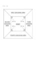
- FIG. 22 is a view for explaining a duplexing area of a sensor duplexing apparatus illustrated in FIG. 21
- FIG. 23 is a view for explaining a duplexing area according to an obstacle a sensor duplexing apparatus illustrated in FIG. 21 .
- an input unit 310 includes a first sensor 311-a mounted at a front left side of the robot, a second sensor 311-b mounted at a front right side of the robot, a third sensor 311-c mounted at a rear left side of the robot, and a fourth sensor 311-d mounted at a rear left side of the robot.
- the logic unit 330 includes a first logic board 331-a corresponding to the first sensor 311-a, a second logic board 331-b corresponding to the second sensor 311-b, a third logic board 331-c corresponding to the third sensor 311-c, and a fourth logic board 331-d corresponding to the fourth sensor 311-d.
- the duplexing area includes a first duplexing area which corresponds to the first sensor 311-a and the second sensor 311-b, a second duplexing area which corresponds to the first sensor 311-a and the third sensor 311-c, a third duplexing area which corresponds to the second sensor 311-b and the fourth sensor 311-d, and a fourth duplexing area which corresponds to the third sensor 311-c and the fourth sensor 311-d.
- the duplexing of the sensor 311 may be implemented in the omni-directional area of the robot (the first duplexing area which is the front area of the robot, the second duplexing area which is the left area of the robot, the third duplexing area which is the right area of the robot, and the fourth duplexing area which is the rear area of the robot.
- the “first duplexing area” which corresponds to the “obstacle A” is identified and the sensor duplexing is performed in the “first duplexing area” using obstacle information detected by two sensors corresponding to the “first duplexing area” : “first sensor 311-a” and “second sensor 311-b”.
- the “second duplexing area” which corresponds to the "obstacle B” is identified and the sensor duplexing is performed in the “second duplexing area” using obstacle information detected by two sensors corresponding to the "second duplexing area”: "first sensor 311-a” and “third sensor 311-c”.
- the "third duplexing area” which corresponds to the "obstacle B” is identified and the sensor duplexing is performed in the “third duplexing area” using obstacle information detected by two sensors corresponding to the "third duplexing area”: "second sensor 311-b” and "fourth sensor 311-d”.
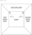
- FIG. 24 is a view for explaining a duplexing area of a sensor duplexing apparatus of a mobile robot according to a third exemplary embodiment of the present disclosure.
- an input unit 310 according to another example of the sensor duplexing apparatus 300 includes a first sensor 311-a mounted at one left side of the robot and a second sensor 311-b mounted at one right side of the robot.
- a logic unit 330 according to another example of the sensor duplexing apparatus 300 includes a first logic board 331-a corresponding to the first sensor 311-a and a second logic board 331-b corresponding to the second sensor 311-b.
- the duplexing area corresponds to the first sensor 311-a and the second sensor 311-b.
- the duplexing of the sensor 311 may be implemented in a specific area of the omni-directional area of the robot.
- the front area of the robot may be configured as a duplexing area by the first sensor 311-a and the second sensor 311-b.
- a left area of the robot is configured by a first single area sensed only by the first sensor 311-a and a right area of the robot is configured by a second single area sensed only by the second sensor 311-b.
- a sensor 311 is not provided so that it is configured as an area which is not sensed.
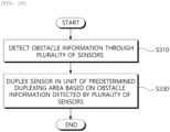
- FIG. 25 is a flowchart for explaining a sensor duplexing method of a mobile robot according to a third exemplary embodiment of the present disclosure.
- the sensor duplexing apparatus 300 detects obstacle information by each of the plurality of sensors 311 (S310).
- the sensor duplexing apparatus 310 detects obstacle information by the sensor 311 based on the dynamic safety zone generated by the sensor 311.
- the dynamic safety zone is dynamically generated based on a movement direction and a movement speed of a robot including a sensor duplexing apparatus 300.
- the sensor duplexing apparatus 300 may duplex a sensor 311 in the unit of predetermined duplexing areas, based on the obstacle information detected by the plurality of sensors 311 (S330).
- the sensor duplexing apparatus 300 may duplex two sensors 311 based on obstacle information detected by two sensors 311 corresponding to the duplexing area.
- the sensor duplexing apparatus 300 may determine that two sensors 311 are successfully duplexed. In contrast, when the obstacle information detected by two sensors 311 corresponding to the duplexing area do not match, the sensor duplexing apparatus 300 may determine that duplexing of two sensors 311 has failed. At this time, the sensor duplexing apparatus 300 may identify whether the obstacle information detected by two sensors 311 corresponding to the duplexing area match using predetermined sensor error information.
- the present invention is not limited to the exemplary embodiment.
- one or more components may be selectively combined to be operated within a scope of the present invention.
- all components may be implemented as one independent hardware but a part or all of the components are selectively combined to be implemented as a computer program which includes a program module which performs a part or all functions combined in one or plural hardwares.
- a computer program may be stored in a computer readable media such as a USB memory, a CD disk, or a flash memory to be read and executed by a computer to implement the exemplary embodiment of the present invention.
- the recording media of the computer program may include a magnetic recording medium or an optical recording medium.
Landscapes
- Engineering & Computer Science (AREA)
- Mechanical Engineering (AREA)
- Robotics (AREA)
- Physics & Mathematics (AREA)
- Remote Sensing (AREA)
- General Physics & Mathematics (AREA)
- Radar, Positioning & Navigation (AREA)
- Automation & Control Theory (AREA)
- Aviation & Aerospace Engineering (AREA)
- Optics & Photonics (AREA)
- Human Computer Interaction (AREA)
- Computer Networks & Wireless Communication (AREA)
- Electromagnetism (AREA)
- Control Of Position, Course, Altitude, Or Attitude Of Moving Bodies (AREA)
- Manipulator (AREA)
Abstract
Description
- The present disclosure relates to a functional safety system of a robot, and more particularly, to an apparatus and a method for generating a dynamic safety zone of a mobile robot which generate a safety zone which is a zone to sense whether there is an obstacle.
- Further, the present disclosure relates to a functional safety system of a robot, and more particularly, to a duplex system architecture modularizing apparatus and method of a mobile robot which duplex a module to satisfy a performance level d (pl-d) required by robot functional safety.
- Furthermore, the present disclosure relates to a functional safety system of a robot, and more particularly, to a sensor duplexing apparatus and method of a mobile robot which duplex a module to satisfy a performance level d (pl-d) required by robot functional safety.
-
FIG. 1 is a view for explaining a method of generating a safety zone of the related art. - When a dynamic safety zone of a robot is generated in the related art, a user receives and stores a shape of a static zone at every speed designated by a user and then if a speed reaches a corresponding speed, it is changed to a zone stored by the user to inspect whether there is an obstacle in the corresponding zone and stop. By doing this, the safety is ensured according to a number and shapes of zones according to a speed designated by the user . As a traveling direction of the robot is diversified, the number of zones according to the speed needs to be increased as many as the traveling directions so that a method of directly inputting the safety zone by the user has limitations according to the number of zones. Aperformance level d (PL-d) LiDAR (light detection and ranging) which uses a dynamic safety zone limits a number of safety zones and a budget model may inputs up to six zones and a high-end model may input up to 32 zones. As on example, a robot using a mecanum wheel which requires various directions travels in both the x-axis and the y-axis and travels while rotating. Therefore, it is difficult for the user to designate an appropriate safety zone according to the speed and the direction for the dynamic driving. Further, as the speed is subdivided to increase the density between zones, the number of zones which need to be input by the user is also increased so that the larger the number of zones, the higher the risk due to the user fault. That is, as illustrated in
FIG. 1 , according to the safety zone generating method of the related art, in a state in which the user matches and stores the speed and the safety zone, when the corresponding condition is satisfied, the safety zone is changed so that the number of safety zones is limited. The higher the density between the safety zones, the larger the number of safety zones and the higher the risk of the user fault by the user. -
FIG. 2 is a view for explaining a duplexing concept for a performance level d withcategory 3 required by a robot functional safety. - In order to ensure a safety of the robot, the duplexing of the module at a performance level (pl) related to the functional safety is being demanded. However, according to the related art, when an existing sensor is removed or a new sensor is added, there is a problem in that a system architecture needs to be changed according to the changed content to satisfy the performance level (pl) of the robot.
- In order to ensure a safety of the robot, the duplexing of the module at a performance level (pl) related to the functional safety is being demanded. The duplex system can be simply implemented using a LiDAR sensor certified for the performance level d (pl-d). However, the LiDAR sensor certified for the performance level d (pl-d) is expensive so that there is a problem in that it takes a lot of money to implement the duplex system. Further, only a function provided by a manufacturer that manufactures the corresponding LiDAR sensor can be used so that it is difficult to flexibly implement a function.
- In order to satisfy pl-d requested by the functional safety of the robot, as illustrated in
FIG. 2 , three module terminals including a input terminal I, a logic terminal L, and an output terminal O need to be duplexed. The input terminal is duplexed to a "LiDAR sensor A (I1)" and a LiDAR sensor B (I2) ", the logic terminal is duplexed to a "LiDAR logic board A (L1) " and a "LiDAR logic board B (L2) ", and the output terminal is duplexed to "01" and "02" and stops when the result is "0" or "2". - An object to be achieved by the present disclosure is to provide an apparatus and a method for generating a dynamic safety zone of a mobile robot which variably generate a safety zone required for a functional safety of a mobile robot according to an appearance and a speed of the mobile robot.
- An object to be achieved by the present disclosure is to provide an apparatus and a method for modularizing a duplex system architecture of a mobile robot which duplex the entire system architecture to satisfy a performance level d (pl-d) demanded by the functional system of a robot.
- An object to be achieved by the present disclosure is to provide an apparatus and a method for modularizing a duplex system architecture of a mobile robot which duplex a sensor using obstacle information detected by a sensor to satisfy a performance level d (pl-d) demanded by the functional system of a robot.
- Other and further objects of the present disclosure which are not specifically described can be further considered within the scope easily deduced from the following detailed description and the effect.
- In order to achieve the above-described objects, according to an aspect of the present disclosure, a dynamic safety zone generating apparatus of a mobile robot includes an information acquiring unit which acquires a movement direction and a movement speed of a mobile robot; and a safety zone generating unit which dynamically generates a safety zone for the mobile robot based onatleast one of shape information of the mobile robot, a movement direction of the mobile robot acquired by the information acquiring unit, and a movement speed of the mobile robot acquired by the information acquiring unit.
- Here, the safety zone generating unit acquires a future predicted position of the mobile robot based on the movement direction and the movement speed of the mobile robot and dynamically generates a safety zone of the mobile robot based on the shape information of the mobile robot and the future predicted location of the mobile robot.
- Here, the dynamic safety zone generating unit acquires the movement speed of the x-axis direction and the movement speed of the y-axis direction based on the movement direction and the movement speed of the mobile robot, acquires the future predicted x-axis location based on the movement speed of the x-axis direction and acquires the future predicted y-axis location of the mobile robot based on the movement speed of the y-axis direction, and acquires a future predicted location of the mobile robot based on the future predicted x-axis location and the future predicted y-axis location.
- Here, the safety zone generating unit acquires a default safety zone based on the shape information of the mobile robot and dynamically generates a safety zone for the mobile robot based on the default safety zone and the future predicted location of the mobile robot.
- Here, the safety zone generating unit acquires front, rear, left, and right distances with respect to the center point of the mobile robot based on the shape information of the mobile robot and acquires a default safety zone formed of four vertices based on the center point of the robot and the front, rear, left, and right distances.
- Here, the safety
zone generating unit 130 varies the front, rear, left, and right distances according to the default safety zone based on the future predicted location of the mobile robot to dynamically generate the safety zone for the mobile robot. Here, the safety zone generating unit acquires a plurality of sub safety zones by varying the front, rear, left, and right distances according to the default safety zone plural times, based on the current location of the mobile robot and the future predicted location of the mobile robot and dynamically generates the safety zone for the mobile robot based on the plurality of sub safety zones. - In order to achieve the above-described objects, according to an aspect of the present disclosure, a sensor duplexing apparatus of a mobile robot an input unit in which a plurality of sensors is mounted; a logic unit in which a plurality of logic boards corresponding to the plurality of sensors mounted in the input unit is mounted; an output unit which transmits an output value to the outside based on the output of the plurality of logic boards mounted in the logic unit; and a controller which duplexes the sensor in the unit of predetermined duplexing areas based on obstacle information detected by each of the plurality of sensors.
- Here, the controller duplexes two sensors based on obstacle information detected by two sensors corresponding to the duplexing area.
- Here, when obstacle information detected by two sensors corresponding to the duplexing area match, the controller determines that duplexing of two sensors is successful and when obstacle information detected by two sensors corresponding to the duplexing area do not match, the controller determines that duplexing of two sensors has failed.
- Here, the controller identifies whether the obstacle information detected by two sensors corresponding to the duplexing area match using predetermined sensor error information.
- Here, the controller duplexes two sensors using obstacle information detected by two sensors based on the dynamic safety zone generated by two sensors corresponding to the duplexing area.
- In order to achieve the above-described objects, according to an aspect of the present disclosure, a duplex system architecture modularizing apparatus of a mobile robot includes an input unit in which a plurality of sensors is mounted; a logic unit in which a plurality of logic boards corresponding to the plurality of sensors mounted in the input unit is mounted; an output unit which transmits an output value to the outside using a duplexing parameter based on the output of the plurality of logic boards mounted in the logic unit; and a controller which changes a value of the duplexing parameter including logic board identification information, logic board type information, and sensor location information based on duplexing target information input by a user.
- According to the apparatus and the method for generating a dynamic safety zone of a mobile robot according to the exemplary embodiment of the present disclosure, an expected location of a mobile robot can be calculated according to a speed/direction by shape information and direction/speed information of a mobile robot without inputting the safety zone by the user and a dynamic safety zone is automatically generated to be used for all mobile robots mounted with various wheels, such as a diff wheel or a Mecanum wheel. Further, the safety zones are automatically generated in all directions without directly inputting the safety zone by the user so that the safety function for the density between the safety zones and omni-directions can be performed and the user fault caused by the user input may be significantly reduced.
- Further, according to the apparatus and the method for modularizing a duplex system architecture of a mobile robot according to an exemplary embodiment of the present disclosure, in order to satisfy the performance level d (pl-d) demanded by the functional safety of the robot, the entire system architecture is duplexed to remove a sensor or add a new sensor without changing the entire system architecture.
- Further, according to the apparatus and the method for duplexing a sensor of a mobile robot according to the exemplary embodiment of the present disclosure, in order to satisfy the performance level d (pl-d) demanded by the functional safety of the robot, the sensor is duplexed using obstacle information detected by the sensor so that a duplex system may be implemented using a cheap general LiDAR sensor which is not certified for pl-d.
- The effects of the present invention are not limited to the technical effects mentioned above, and other effects which are not mentioned can be clearly understood by those skilled in the art from the following description
-
-
FIG. 1 is a view for explaining a method of generating a safety zone of the related art; -
FIG. 2 is a view for explaining a duplexing concept for a performance level d withcategory 3 required by a robot functional safety; -
FIG. 3 is a block diagram for explaining an apparatus of generating a dynamic safety zone of a mobile robot according to a first exemplary embodiment of the present disclosure; -
FIG. 4 is a view for explaining a process of generating a dynamic safety zone according to a first exemplary embodiment of the present disclosure; -
FIG. 5 is a view for explaining an operation of acquiring a default safety zone according to a first exemplary embodiment of the present disclosure; -
FIG. 6 is a view for explaining an operation of acquiring a future predicted location according to a first exemplary embodiment of the present disclosure; -
FIG. 7 is a view for explaining an operation of generating a dynamic safety zone according to a first exemplary embodiment of the present disclosure; -
FIG. 8 is a view for explaining an example of generating a dynamic safety zone according to a first exemplary embodiment of the present disclosure to illustrate a straight movement on one axis; -
FIG. 9 is a view for explaining an operation of generating a dynamic safety zone for diagonal movement according to a first exemplary embodiment of the present disclosure; -
FIG. 10 is a view for explaining an example of generating a dynamic safety zone according to a first exemplary embodiment of the present disclosure to illustrate a diagonal movement on an x-axis and a y-axis; -
FIG. 11 is a view for explaining an operation of generating a dynamic safety zone of rotational movement according to a first exemplary embodiment of the present disclosure; -
FIG. 12 is a view for explaining an example of generating a dynamic safety zone according to a first exemplary embodiment of the present disclosure to illustrate a rotational movement; -
FIG. 13 is a view for explaining an example of generating a dynamic safety zone according to a first exemplary embodiment of the present disclosure to illustrate a case in which a rotational movement and a straight movement simultaneously occur; -
FIG. 14 is a flowchart for explaining a method for generating a dynamic safety zone of a mobile robot according to a first exemplary embodiment of the present disclosure; -
FIG. 15 is a block diagram for explaining an apparatus for modularizing a duplex system architecture of a mobile robot according to a second exemplary embodiment of the present disclosure; -
FIG. 16 is a block diagram for explaining a sub configuration of a duplex system architecture modularizing apparatus illustrated inFIG. 15 ; -
FIG. 17 is a view for explaining an implementation example of a duplex system architecture modularizing apparatus of a mobile robot according to a second exemplary embodiment of the present disclosure; -
FIG. 18 is a flowchart for explaining a method for modularizing a duplex system architecture of a mobile robot according to a second exemplary embodiment of the present disclosure; -
FIG. 19 is a block diagram for explaining a sensor duplexing apparatus of a mobile robot according to a third exemplary embodiment of the present disclosure; -
FIG. 20 is a diagram illustrating a process of duplexing a sensor according to a third embodiment of the present disclosure; -
FIG. 21 is a block diagram for explaining an input unit and a logic unit of an example of a sensor duplexing apparatus of a mobile robot according to a third exemplary embodiment of the present disclosure; -
FIG. 22 is a view for explaining a duplexing area of a sensor duplexing apparatus illustrated inFIG. 21 ; -
FIG. 23 is a view for explaining a duplexing area according to an obstacle a sensor duplexing apparatus illustrated inFIG. 21 ; -
FIG. 24 is a view for explaining an duplexing area of a sensor duplexing apparatus of a mobile robot according to a third exemplary embodiment of the present disclosure; and -
FIG. 25 is a flowchart for explaining a sensor duplexing method of a mobile robot according to a third exemplary embodiment of the present disclosure. - Hereinafter, embodiments of the present invention will be described in detail with reference to the accompanying drawings . Advantages and features of the present disclosure, and methods for accomplishing the same will be more clearly understood from exemplary embodiments described below with reference to the accompanying drawings. However, the present invention is not limited to exemplary embodiments disclosed herein but will be implemented in various different forms. The exemplary embodiments are provided by way of example only so that a person of ordinary skilled in the art can fully understand the disclosures of the present invention and the scope of the present invention. Therefore, the present invention will be defined only by the scope of the appended claims . Like reference numerals generally denote like elements throughout the specification. Unless otherwise defined, all terms (including technical and scientific terms) used in the present specification may be used as the meaning which may be commonly understood by the person with ordinary skill in the art, to which the present invention belongs. It will be further understood that terms defined in commonly used dictionaries should not be interpreted in an idealized or excessive sense unless expressly and specifically defined.
- In the specification, the terms "first" or "second" are used to distinguish one component from the other component so that the scope should not be limited by these terms . For example, a first component may be referred to as a second component, and similarly, a second component may be referred to as a first component.
- In the present specification, in each step, numerical symbols (for example, a, b, and c) are used for the convenience of description, but do not explain the order of the steps so that unless the context apparently indicates a specific order, the order may be different from the order described in the specification. That is, the steps may be performed in the order as described or simultaneously, or an opposite order.
- In this specification, the terms "have", "may have", "include", or "may include" represent the presence of the characteristic (for example, a numerical value, a function, an operation, or a component such as a part"), but do not exclude the presence of additional characteristic.
- The term "~unit" used in the specification refers to a software or hardware component such as a field programmable gate array (FPGA) or an ASIC and "-unit" performs some functions. However, "~unit" is not limited to the software or the hardware. "~unit" may be configured to be in an addressable storage medium or may be configured to reproduce one or more processors. Accordingly, as an example, "-unit" includes components such as software components, object oriented software components, class components, and task components, processes, functions, attributes, procedures, subroutines, segments of a program code, drivers, a firmware, a microcode, a circuit, data, database, and data structures. A function which is provided in the components and "~units" may be combined with a smaller number of components and "~units" or divided into additional components and "~units".
- Hereinafter, a functional safety system of a robot according to the present disclosure will be described in detail with reference to the accompanying drawing.
- The functional safety system of a robot according to the present disclosure dynamically generates a safety zone and duplexes a system module and a LiDAR sensor for a performance level d (pl-d).
- An apparatus and a method for generating a dynamic safety zone of a mobile robot which is a first exemplary embodiment of a functional safety system of a robot according to the present disclosure will be described in detail with reference to
FIGS. 3 to 14 . - First, an apparatus for generating a dynamic safety zone of a mobile robot according to a first exemplary embodiment of the present disclosure will be described with reference to
FIGS . 3 to 7 . -
FIG. 3 is a block diagram for explaining an apparatus of generating a dynamic safety zone of a mobile robot according to a first exemplary embodiment of the present disclosure,FIG. 4 is a view for explaining a process of generating a dynamic safety zone according to a first exemplary embodiment of the present disclosure,FIG. 5 is a view for explaining an operation of acquiring a default safety zone according to a first exemplary embodiment of the present disclosure,FIG. 6 is a view for explaining an operation of acquiring a future predicted location according to a first exemplary embodiment of the present disclosure, andFIG. 7 is a view for explaining an operation of generating a dynamic safety zone according to a first exemplary embodiment of the present disclosure. - Referring to
FIG. 3 , anapparatus 100 for generating a dynamic safety zone of a mobile robot according to a first exemplary embodiment of the present disclosure (hereinafter, referred to as a "dynamic safety zone generating apparatus") variably generates a safety zone required for the functional safety of the mobile robot according to an appearance and a speed of the mobile robot. - Here, the present disclosure is applicable to household cleaning robots, public building cleaning robots, logistics robots, service robots, as well as industrial robots.
That is, the dynamic safetyzone generating apparatus 100 according to the present disclosure is free from a method having a limitation for a number of safety zones and a high risk of a user fault due to a method of directly inputting a safety zone by a user according to a speed and a direction of the mobile robot, which is a method according to a related art, and calculates a predicted location of a mobile robot according to a speed/direction by shape information and direction/speed information of the mobile robot without inputting a safety zone by a user and automatically generates a dynamic safety zone to be used for all mobile robots mounted with various wheels such as a diff wheel and a Mecanum wheel. Accordingly, unlike a safety zone generating method of the related art in which a safety zone set by the user is not selectively changed, according to the present disclosure, the safety zone is automatically generated for all directions without directly inputting the safety zone by a user so that the safety function for the density between the safety zones and omni-directions may be performed and a user fault by the user input may be significantly reduced. - In the meantime, the dynamic safety
zone generating apparatus 100 according to the present disclosure is loaded in a mobile robot to dynamically generate a safety zone based on information acquired from the sensor mounted in the mobile robot. The dynamic safetyzone generating apparatus 100 according to the present disclosure is loaded in a server which remotely manages the mobile robot by wireless communication to dynamically generate the safety zone of the mobile robot based on the information provided from the mobile robot and provide information about the generated safety zone to the mobile robot. To this end, the dynamic safetyzone generating apparatus 100 includes aninformation acquiring unit 110 and a safetyzone generating unit 130. - The
information generating unit 110 acquires a movement direction and a movement speed of the mobile robot. - Here, the movement direction of the mobile robot refers to one of a traveling direction according to a straight movement of the mobile robot, a traveling direction according to the rotation of the mobile robot, and a traveling direction when the rotational movement and the straight movement of the mobile robot are simultaneously generated.
- The straight movement of the mobile robot refers to one of a straight movement on the x-axis, a straight movement on the y-axis, and a diagonal movement on the x-axis and the y-axis. The rotation of the mobile robot refers to one of the rotational movement to the left side and the rotational movement to the right side.
- The safety
zone generating unit 130 dynamically generates a safety zone for the mobile robot based on at least one of shape information of the mobile robot, a movement direction of the mobile robot acquired by theinformation acquiring unit 110, and a movement speed of the mobile robot acquired by theinformation acquiring unit 110. - At this time, the safety
zone generating unit 130 dynamically generates the safety zone for the mobile robot in the unit of predetermined cycles. The safetyzone generating unit 130 dynamically generates the safety zone of the mobile robot when at least one of the movement direction and the movement speed of the mobile changes. - To be more specific, the safety
zone generating unit 130 acquires a future predicted position of the mobile robot based on the movement direction and the movement speed of the mobile robot. For example, as illustrated inFIG. 6 , the safetyzone generating unit 130 may acquire a future location of the mobile robot to be predicted with respect a current center location of the mobile robot, based on the movement direction and the movement speed of the mobile robot. - That is, the safety
zone generating unit 130 may acquire the movement speed of the x-axis direction and the movement speed of the y-axis direction based on the movement direction and the movement speed of the mobile robot. The safetyzone generating unit 130 may acquire a future predicted x-axis location of the mobile robot based on the movement speed of the x-axis direction and a future predicted y-axis location of the mobile robot based on the movement speed of the y-axis direction. The safetyzone generating unit 130 acquires the future predicted location of the mobile robot based on the future predicted x-axis location and the future predicted y-axis location. - For example, the safety
zone generating unit 130 acquires the future predicted location of the mobile robot by means of the followingEquation 1.
- Here, future location.x indicates the future predicted x-axis location and future location.y indicates the future predicted y-axis location. speed.x indicates a movement speed of the x-axis direction of the mobile robot and speed, y indicates a movement speed of the y-axis direction of the mobile robot. braking distance indicates a distance required to stop the mobile robot and is set in advance according to the speed of the mobile robot. margin distance indicates a margin distance which is set in advance for the safety of the mobile robot. response time is a response time of a sensor mounted in the mobile robot and is acquired by the following
Equation 2.
- Here, sensor scanning time indicates a scanning time of the sensor mounted in the mobile robot. sampling count indicates a number of samplings of the sensor mounted in the mobile robot. communication delay indicates a communication delay time of the sensor mounted in the mobile robot. margin response time indicates a margin response time which is set in advance for exact measurement of the sensor mounted in the mobile robot. The safety
zone generating unit 130 may dynamically generate a safety zone for the mobile robot based on the shape information of the mobile robot and the future predicted location of the mobile robot. Here, the shape information of the mobile robot refers to information about the appearance of the robot. - That is, the safety
zone generating unit 130 may acquire a default safety zone based on the shape information of the mobile robot and dynamically generate a safety zone for the mobile robot based on the default safety zone and the future predicted location of the mobile robot. - At this time, the safety
zone generating unit 130 acquires front, rear, left, and right distances with respect to the center point of the mobile robot based on the shape information of the mobile robot and acquires a default safety zone formed of four vertices based on the center point of the robot and the front, rear, left, and right distances. For example, as illustrated inFIG. 5 , the safetyzone generating unit 130 acquires a first distance (a front side distance), a second distance (a rear side distance), a third distance (a left side distance), and a fourth distance (a right side distance) with respect to the center point of the mobile robot and acquires a default safety zone based on the acquired first to fourth distances. - Further, the safety
zone generating unit 130 varies the front, rear, left, and right distances according to the default safety zone based on the future predicted location of the mobile robot to dynamically generate the safety zone for the mobile robot. For example, as illustrated inFIG. 7 , the safetyzone generating unit 130 dynamically generates the safety zone by referring to the future predicted location of the mobile robot based on the default safety zone with respect to the current center position of the mobile robot. At this time, the distance of the safety zone is acquired by the followingEquation 3.
- Here, speed indicates a movement speed of the mobile robot. response time is a response time of a sensor mounted in the mobile robot and is acquired by the
above Equation 2. braking distance indicates a distance required to stop the mobile robot and is set in advance according to the speed of the mobile robot. margin distance indicates a margin distance which is set in advance for the safety of the mobile robot. - At this time, the safety
zone generating unit 130 acquires a plurality of sub safety zones by varying the front, rear, left, and right distances according to the default safety zone plural times, based on the current location of the mobile robot and the future predicted location of the mobile robot and dynamically generates the safety zone for the mobile robot based on the plurality of sub safety zones. For example, the safetyzone generating unit 130 acquires a sub safety zone in every predetermined distance unit, by dividing a path along which the mobile robot moves from a start point to a target time into a predetermined distance unit with the current location of the mobile robot as the start point and the future predicted location of the mobile robot as the target point and dynamically generates the safety zone for the mobile robot by overlapping the plurality of acquired sub safety zones. - Now, an example of generating a dynamic safety zone according to the first exemplary embodiment of the present disclosure will be described with reference to
FIGS. 8 to 13 . -
FIG. 8 is a view for explaining an example of generating a dynamic safety zone according to a first exemplary embodiment of the present disclosure to illustrate a straight movement on one axis,FIG. 9 is a view for explaining an operation of generating a dynamic safety zone for diagonal movement according to a first exemplary embodiment of the present disclosure,FIG. 10 is a view for explaining an example of generating a dynamic safety zone according to a first exemplary embodiment of the present disclosure to illustrate a diagonal movement on an x-axis and a y-axis,FIG. 11 is a view for explaining an operation of generating a dynamic safety zone of rotational movement according to a first exemplary embodiment of the present disclosure,FIG. 12 is a view for explaining an example of generating a dynamic safety zone according to a first exemplary embodiment of the present disclosure to illustrate a rotational movement, andFIG. 13 is a view for explaining an example of generating a dynamic safety zone according to a first exemplary embodiment of the present disclosure to illustrate a case in which a rotational movement and a straight movement simultaneously occur. - Referring to
FIG. 8 , the faster the speed, the longer the length of the safety zone which is dynamically generated and the slower the speed, the smaller the safety zone. However, the safety zone which is dynamically generated should not be smaller than the shape of the mobile robot, that is, the default safety zone. - Referring to
FIGS. 9 and10 , when the mobile robot simultaneously moves to the x-axis and the y-axis, the mobile robot diagonally travels and the safety zone is dynamically and automatically generated so that the mobile robot does not collide with the obstacle during the diagonal traveling. - Referring to
FIGS. 11 and12 , a shape of the safety zone which is dynamically generated according to the rotation direction of the mobile robot is changed so that when the mobile robot rotates to the right side, a upper right end and an upper left end which are likely to collide become longer and when the mobile robot rotates to the left side, the upper left end and the lower right end may become longer. - Referring to
FIG. 13 , when the rotational movement and the straight movement of the mobile robot are simultaneously generated so that there are a straight movement speed and a rotation speed simultaneously, a safety zone in which a rotational value is added based on a value obtained from the future predicted location of the mobile robot is generated and all the safety zones are automatically determined and changed according to the speed and the direction. - Now, a method for generating a dynamic safety zone of a mobile robot according to a first exemplary embodiment of the present disclosure will be described with reference to
FIG. 14 . -
FIG. 14 is a flowchart for explaining a method for generating a dynamic safety zone of a mobile robot according to a first exemplary embodiment of the present disclosure. - Referring to
FIG. 14 , the dynamic safetyzone generating apparatus 100 acquires a movement direction and a movement speed of the mobile robot (S110). - By doing this, the dynamic safety
zone generating apparatus 100 dynamically generates the safety zone for the mobile robot based on at least one of the shape information of the mobile robot, the movement direction of the mobile robot, and the movement speed of the mobile robot (S130). - At this time, the dynamic safety
zone generating apparatus 100 dynamically generates the safety zone for the mobile robot in the unit of predetermined cycles. The dynamic safetyzone generating apparatus 100 dynamically generates the safety zone of the mobile robot when at least one of the movement direction and the movement speed of the mobile changes. - To be more specific, the dynamic safety
zone generating apparatus 100 acquires a future predicted location of the mobile robot based on the movement direction and the movement speed of the mobile robot. That is, the dynamic safetyzone generating apparatus 100 acquires the movement speed of the x-axis direction and the movement speed of the y-axis direction based on the movement direction and the movement speed of the mobile robot, acquires the future predicted x-axis location of the mobile robot based on the movement speed of the x-axis direction and acquires the future predicted y-axis location of the mobile robot based on the movement speed of the y-axis direction, and acquires a future predicted location of the mobile robot based on the future predicted x-axis location and the future predicted y-axis location. - The dynamic safety
zone generating apparatus 100 may dynamically generate a safety zone for the mobile robot based on the shape information of the mobile robot and the future predicted location of the mobile robot. - That is, the dynamic safety
zone generating apparatus 100 may acquire a default safety zone based on the shape information of the mobile robot and dynamically generate a safety zone for the mobile robot based on the default safety zone and the future predicted location of the mobile robot. At this time, the dynamic safetyzone generating apparatus 100 acquires front, rear, left, and right distances with respect to the center point of the mobile robot based on the shape information of the mobile robot and acquires a default safety zone formed of four vertices based on the center point of the robot and the front, rear, left, and right distances. - Further, the dynamic safety
zone generating apparatus 100 varies the front, rear, left, and right distances according to the default safety zone based on the future predicted location of the mobile robot to dynamically generate the safety zone for the mobile robot. At this time, the dynamic safetyzone generating apparatus 100 acquires a plurality of sub safety zones by varying the front, rear, left, and right distances according to the default safety zone plural times, based on the current location of the mobile robot and the future predicted location of the mobile robot and dynamically generates the safety zone for the mobile robot based on the plurality of sub safety zones. - An apparatus and a method for modularizing a duplex system architecture of a mobile robot which is a second exemplary embodiment of a functional safety system of a robot according to the present disclosure will be described in detail with reference to
FIGS. 15 to 18 . - First, an apparatus for modularizing a duplex system architecture of a mobile robot according to a second embodiment of the present disclosure will be described with reference to
FIG. 15 . -
FIG. 15 is a block diagram for explaining an apparatus for modularizing a duplex system architecture of a mobile robot according to a second exemplary embodiment of the present disclosure. - Referring to
FIG. 15 , the apparatus 200 for modularizing a duplex system architecture of a mobile robot according to a second exemplary embodiment of the present disclosure (hereinafter, referred to as a "modularizing apparatus") may duplex the entire system architecture to satisfy the pl-d (performance level d) requested by the robot functional safety. Here, the present disclosure is applicable to household cleaning robots, public building cleaning robots, logistics robots, service robots, as well as industrial robots. - In order to satisfy pl-d requested by the functional safety of the robot, as illustrated in
FIG. 2 , three module terminals including a input terminal I, a logic terminal L, and an output terminal O need to be duplexed. The input terminal is duplexed to a "LiDAR sensor A (I1)" and a LiDAR sensor B(I2)", the logic terminal is duplexed to a "LiDAR logic board A (L1)" and a "LiDAR logic board B (L2) ", and the output terminal is duplexed to "01" and "02" and stops when the result is "0" or "2". The present disclosure relates to a method for performing the duplexing in view of the entire system architecture. - To this end, the modularizing apparatus 200 includes an
input unit 210, alogic unit 230, anoutput unit 250, and acontroller 270. - A plurality of
sensors 211 may be mounted in theinput unit 210. - Here, the
sensor 211 may be one of a LiDAR sensor, an encoder sensor, and a cliff sensor. - In the
logic unit 230, a plurality oflogic boards 231 corresponding to the plurality ofsensors 211 mounted in theinput unit 210 may be mounted.
Here, thelogic board 231 may be one of a LiDAR board, an encoder board, and the other (ETC) board. - The
output unit 250 transmits an output value to the outside using a duplexing parameter based on outputs of the plurality oflogic boards 231 mounted in thelogic unit 230. - The
controller 270 may change a value of the duplexing parameter based on duplexing target information input by the user. - Here, the duplexing parameter includes logic board identification information which is unique information to identify the
logic board 231, logic board type information which is information to identify a type of thelogic board 231, and sensor location information which is information to identify the location of thesensor 211. - Now, the duplex system architecture modularizing apparatus of a mobile robot according to a second embodiment of the present disclosure will be described in more detail with reference to
FIG. 16 . -
FIG. 16 is a block diagram for explaining a sub configuration of a duplex system architecture modularizing apparatus illustrated inFIG. 15 . - Referring to
FIG. 16 , in theinput unit 210 of the modularizing apparatus 200 according to the present disclosure, a plurality of "type A" sensors A 211-a is mounted, a plurality of "type B" sensors B 211-b is mounted, and a plurality of "type C" sensors C 211-c is mounted. Here, the "type A" refers to the LiDAR sensor, the "type B" refers to an Encoder sensor, and the "type C" refers to the Cliff sensor. - The
logic unit 230 of the modularizing apparatus 200 includes a plurality of "type A" logic boards A 231-a mounted corresponding to the plurality of sensors A211-a mounted in theinput unit 210, a plurality of "type B" logic boards B 231-b mounted corresponding to the plurality of sensors B 211-b mounted in theinput unit 210, and a plurality of "type C" logic boards C 231-c mounted corresponding to the plurality of sensors C 211-c mounted in theinput unit 210. Here, the "type A" refers to the LiDAR board, the "type B" refers to an Encoder board, and the "type C" refers to the Cliff board. - Further, the plurality of
logic boards 231 mounted in thelogic unit 230, that is, the plurality of logic boards A 231-a, the plurality of logic boards B 231-b, and the plurality of logic boards C 231-c are connected to one communication network. When duplexing target information is input by the user, thecontroller 270 of the modularizing apparatus 200 changes the value of the duplexing parameter in the unit of the duplexing target set based on the duplexing target information. Here, the duplexing target information includes logic board identification information of a duplexing target and sensor information corresponding to the logic board of the duplexing target. - To be more specific, the
controller 270 may change the value of the duplexing parameter including a first pair of logic board identification information, a first pair of logic board type information, a first pair of sensor location information, a second pair of logic board identification information, a second pair of logic board type information, and a second pair of sensor location information in the unit of duplexing target sets to dynamically changes the duplexing target. - At this time, the
output unit 250 includes two ORgates gates logic boards 231 and transmits the output values of two ORgates - That is, the
controller 270 controls theoutput unit 250 based on the duplexing target information to set the output of the logic board corresponding to the first pair of duplexing target sets to be input to the first OR gate and to set the output of the logic board corresponding to the second pair of duplexing target sets to be input to the second OR gate. - For example, the sensors A 211-a which are two LiDAR sensors, the sensors B 211-b which are two Encoder sensors, and the sensors C 211-c which are two Cliff sensors are installed in the
input unit 210 and the logic board A 231-a which are two LiDAR boards corresponding to two sensors A 211-a, the logic board B 231-b which are two Encoder boards corresponding to two sensors B 231-b, and the logic boards C 231-c which are two ETC boards corresponding to two sensors C 211-c are installed, and then the duplexing target information as follows may be input. -
- -> Duplexing target set 1: Identification information of two logic boards A 231-a, number of
sensors 211 connected to two logic boards A 231-a, and identification information ofsensor 211 - -> Duplexing target set 2: Identification information of two logic boards B 231-b, number of
sensors 211 connected to two logic boards B 231-b, and identification information ofsensor 211 - -> Duplexing target set 3: Identification information of two logic boards C 231-c, number of
sensors 211 connected to two logic boards C 231-c, and identification information ofsensor 210 - By doing this, the
controller 270 of the modularizing apparatus 200 according to the present disclosure changes the value of the duplexing parameter in the unit of duplexing target set as follows, based on the above duplexing target information to dynamically change the duplexing target. -
- -> Duplexing target set 1: A value of related duplexing parameter is changed with one logic board A 231-a between two logic boards A 231-a as a first pair and the other logic board A 231-a as a second pair to set two logic boards A 231-a as a duplexing target
- -> Duplexing target set 2: A value of related duplexing parameter is changed with one logic board B 231-b between two logic boards B 231-b as a first pair and the other logic board B 231-b as a second pair to set two logic boards B 231-b as a duplexing target
- -> Duplexing target set 3: A value of related duplexing parameter is changed with one logic board C 231-c between two logic boards C 231-c as a first pair and the other logic board C 231-c as a second pair to set two logic boards C 231-c as a duplexing target
- The
controller 270 may set to input one logic board A 231-a between two logic boards A 231-a set as the first pair, one logic board B 231-b between two logic boards A 231-b set as the first pair, and one logic board C 231-c between two logic boards C 231-c set as the first pair to the first ORgate 251. Further, thecontroller 270 may set to input one logic board A 231-a between two logic boards A 231-a set as the second pair, one logic board B 231-b between two logic boards A 231-b set as the second pair, and one logic board C 231-c between two logic boards C 231-c set as the second pair to the second ORgate 252. By doing this, according to the present disclosure, the output terminal may be duplexed. - Now, an implementation example of a duplex system architecture modularizing apparatus of a mobile robot according to a second embodiment of the present disclosure will be described with reference to
FIG. 17 . -
FIG. 17 is a view for explaining an implementation example of a duplex system architecture modularizing apparatus of a mobile robot according to a second exemplary embodiment of the present disclosure. - Referring to
FIG. 17 , according to the present disclosure, the entire system is configured by dividing an input terminal I, a logic terminal L, and an output terminal O and eachlogic board LB 231 is formed by one communication network to remove or add a module to thelogic board LB 231 in accordance with the number ofsensors 211 required for duplexing. - Further, in the output terminal, in order to flexibly receive data regardless of the number of two duplexed data, two OR
gates logic board LB 231 is removed or newly added, the duplex system may be implemented without changing the entire system architecture. - That is, according to the present disclosure, the
logic board LB 231 is configured for everysensor 211 to configure a duplex system in the unit of modules and the output terminal is duplexed using the output board (two OR gates) which are duplexed regardless of the number of output data from the entire logic terminals so that the pl-d architecture is possible without causing a big change of the entire duplex system architecture whenever the number ofsensors 211 changes. - In the system architecture according to the present disclosure, the logic terminal is largely divided into three types: a LiDAR board, an encoder board, and an ETC board. At this time, the number of LiDAR sensors dynamically changes to two to four, the number of Encoder sensors dynamically changes to two to four, and the number of Cliff sensors dynamically changes to four to eight. The number of
sensors 211 may change without separately changing the software in the board and the user may transmit the changed content to the corresponding board as data of the parameter. That is, the user may transmit the changed content to the corresponding board by inputting the duplexing target information. - When the user inputs the duplexing target information such as an ID number of the
logic board 231 to be duplexed and the number ofsensors 211, the corresponding board automatically changes a value of the following duplexing parameter based on the duplexing target information through an internal algorithm. - First pair of duplexing parameters to be duplexed
- ID of logic board 231: LB_PAIR_RS485_ID_1
- Type of logic board 231: LB_PAIR_EXTRINSIC_TYPE_1
- Location of sensor 211: LB_PAIR_LIDAR_LOCATION_XYZ_1 / LB_PAIR_LIDAR_LOCATION_R_XYZ_1
- Second pair of duplexing parameters to be duplexed
- ID of logic board 231: LB_PAIR_RS485_ID_2
- Type of logic board 231: LB_PAIR_EXTRINSIC_TYPE_2
- Location of sensor 211: LB_PAIR_LIDAR_LOCATION_XYZ_2 / LB_PAIR_LIDAR_LOCATION_R_XYZ_2
- In the internal board, the target to be duplexed may be dynamically changed by the duplexing parameter as described above. That is, according to the present disclosure, after changing the number of sensors to be changed in the unit of systems, when only the value of the duplexing parameter is changed in accordance therewith, the duplexing target is automatically changed.
- Now, an method for modularizing a duplex system architecture of a mobile robot according to a second embodiment of the present disclosure will be described with reference to
FIG. 18 . -
FIG. 18 is a flowchart for explaining a method for modularizing a duplex system architecture of a mobile robot according to a second exemplary embodiment of the present disclosure. - Referring to
FIG. 18 , the modularizing apparatus 200 according to the present disclosure inputs duplexing target information by a user (S210). - Here, the duplexing target information includes logic board identification information of a duplexing target and sensor information corresponding to the logic board of the duplexing target.
- Next, the modularizing apparatus 200 changes the value of the duplexing parameter based on the duplexing target information (S230).
- Here, the duplexing parameter includes logic board identification information which is unique information to identify the
logic board 231, logic board type information which is information to identify a type of thelogic board 231, and sensor location information which is information to identify the location of thesensor 211. - That is, when duplexing target information is input by the user, the modularizing apparatus 200 changes the value of the duplexing parameter in the unit of the duplexing target set based on the duplexing target information.
- To be more specific, the modularizing apparatus 200 may change the value of the duplexing parameter including a first pair of logic board identification information, a first pair of logic board type information, a first pair of sensor location information, a second pair of logic board identification information, a second pair of logic board type information, and a second pair of sensor location information in the unit of duplexing target sets to dynamically changes the duplexing target.
- At this time, the
output unit 250 of the modularizing apparatus 200 includes two ORgates gates logic boards 231 and transmits the output values of two ORgates output unit 250 based on the duplexing target information to set the output of the logic board corresponding to the first pair of duplexing target sets to be input to the first OR gate and the output of the logic board corresponding to the second pair of duplexing target sets to be input to the second OR gate. - An apparatus and a method for duplexing a sensor of a mobile robot which is a third exemplary embodiment of a functional safety system of a robot according to the present disclosure will be described in detail with reference to
FIGS. 19 to 25 . - First, an apparatus for duplexing a sensor of a mobile robot according to a third exemplary embodiment of the present disclosure will be described with reference to
FIGS. 19 and20 . -
FIG. 19 is a block diagram for explaining a sensor duplexing apparatus of a mobile robot according to a third exemplary embodiment of the present disclosure andFIG. 20 is a diagram illustrating a process of duplexing a sensor according to a third embodiment of the present disclosure. - Referring to
FIG. 19 , theapparatus 300 for duplexing a sensor of a mobile robot according to a second exemplary embodiment of the present disclosure (hereinafter, referred to as a "sensor duplexing apparatus") may duplex a sensor using obstacle information detected by the sensor to satisfy the pl-d (performance level d) requested by the robot functional safety. Here, the present disclosure is applicable to household cleaning robots, public building cleaning robots, logistics robots, service robots, as well as industrial robots. - In order to satisfy pl-d requested by the functional safety of the robot, as illustrated in
FIG. 2 , three module terminals including a input terminal I, a logic terminal L, and an output terminal O need to be duplexed. The input terminal is duplexed to a "LiDAR sensor A (I1)" and a LiDAR sensor B(I2)", the logic terminal is duplexed to a "LiDAR logic board A (L1)" and a "LiDAR logic board B (L2) ", and the output terminal is duplexed to "01" and "02" and stops when the result is "0" or "2". The present disclosure relates to a method for duplexing two LiDAR sensors using an obstacle present in a safety zone, by two LiDAR sensors which configures the logic terminal, rather than the view point of the system architecture. - To this end, the
sensor duplexing apparatus 300 includes aninput unit 310, alogic unit 330, anoutput unit 350, and acontroller 370. - A plurality of
sensors 311 may be mounted in theinput unit 310. - Here, the sensor may be a LiDAR sensor.
- In the
logic unit 330, a plurality of logic boards corresponding to the plurality ofsensors 311 mounted in theinput unit 310 may be mounted. - Here, the logic board may be a LiDAR board.
- The
output unit 350 transmits an output value to the outside based on outputs of the plurality oflogic boards 331 mounted in thelogic unit 330. - The
controller 370 may duplex a sensor in the unit of predetermined duplexing areas, based on the obstacle information detected by the plurality ofsensors 311. - Here, the duplexing area refers to a spatial area which is duplexed using obstacle information detected by two
sensors 311 to satisfy pl-d (performance level d) requested by the functional safety. - That is, the
controller 370 may duplex twosensors 311 based on obstacle information detected by twosensors 311 corresponding to the duplexing area. - To be more specific, the
controller 370 may duplex twosensors 311 using obstacle information detected by twosensors 311 based on a dynamic safety zone generated by twosensors 311 corresponding to the duplexing area. At this time, the dynamic safety zone may be dynamically generated based on the movement direction and the movement speed of the robot in which thesensor duplexing apparatus 300 is mounted and the detailed description thereof is the same as the above-described first exemplary embodiment according to the present disclosure. - Here, when the obstacle information detected by two
sensors 311 corresponding to the duplexing area match, thecontroller 370 may determine that twosensors 311 are successfully duplexed. Here, when the obstacle information detected by twosensors 311 corresponding to the duplexing area match, thecontroller 370 may determine that the duplexing of twosensors 311 has failed. At this time, thecontroller 370 may identify whether the obstacle information detected by twosensors 311 corresponding to the duplexing area match using predetermined sensor error information. - For example, as illustrated in
FIG. 20 , when "sensor A" and "sensor B" correspond to the duplexing area, an obstacle is detected from a dynamic safety zone generated by the "sensor A" to obtain obstacle information and an obstacle is detected from a dynamic safety zone generated by the "sensor B" to obtain obstacle information. Next, the "sensor A" and the "sensor B" are duplexed using the obstacle information detected by the "sensor A" and the obstacle information detected by the "sensor B". That is, it is identified whether the obstacle information detected by the "sensor A" and the obstacle information detected by the "sensor B" match. At this time, when the obstacle according to the obstacle information is located in a boundary of adjacent duplexing areas, it is identified whether the obstacle information detected by the "sensor A" and the obstacle information detected by the "sensor B" match using sensor error information. As a result of identification, if the information match, it is determined that the "sensor A" and the "sensor B" are successfully duplexed and if not, it is determined that the duplexing of the "sensor A" and the "sensor B" has failed. In the meantime, thelogic board 331 and thecontroller 370 are integrally implemented so that thelogic board 331 performs an operation of thecontroller 370. - That is, the
logic board 331 may duplex twosensors 311 based on obstacle information detected by twosensors 311 corresponding to the duplexing area. - For example, when the "sensor A" and the "sensor B" correspond to the duplexing area, the "logic board A" corresponds to the "sensor A", and the "logic board B" corresponds to the "sensor B", if the "logic board A" acquires obstacle information detected by the "sensor A", the "logic board A" identifies the duplexing area from which the obstacle is detected based on the obstacle information detected by the "sensor A". When the identified duplexing area is a duplexing area which corresponds to the "sensor A" and the "sensor B", the "logic board A" is supplied with the obstacle information detected by the "sensor B" from the "logic board B". By doing this, the "logic board A" identifies whether the obstacle information detected by the "sensor A" and the obstacle information detected by the "sensor B" match.
- Now, an example of an apparatus for duplexing a sensor of a mobile robot according to a third exemplary embodiment of the present disclosure will be described with reference to
FIGS. 21 to 23 . -
FIG. 21 is a block diagram for explaining an input unit and a logic unit of an example of a sensor duplexing apparatus of a mobile robot according to a third exemplary embodiment of the present disclosure,FIG. 22 is a view for explaining a duplexing area of a sensor duplexing apparatus illustrated inFIG. 21 , andFIG. 23 is a view for explaining a duplexing area according to an obstacle a sensor duplexing apparatus illustrated inFIG. 21 . - Referring to
FIGS. 21 and22 , aninput unit 310 according to an example of thesensor duplexing apparatus 300 includes a first sensor 311-a mounted at a front left side of the robot, a second sensor 311-b mounted at a front right side of the robot, a third sensor 311-c mounted at a rear left side of the robot, and a fourth sensor 311-d mounted at a rear left side of the robot. - The
logic unit 330 according to an example of thesensor duplexing apparatus 300 includes a first logic board 331-a corresponding to the first sensor 311-a, a second logic board 331-b corresponding to the second sensor 311-b, a third logic board 331-c corresponding to the third sensor 311-c, and a fourth logic board 331-d corresponding to the fourth sensor 311-d. The duplexing area includes a first duplexing area which corresponds to the first sensor 311-a and the second sensor 311-b, a second duplexing area which corresponds to the first sensor 311-a and the third sensor 311-c, a third duplexing area which corresponds to the second sensor 311-b and the fourth sensor 311-d, and a fourth duplexing area which corresponds to the third sensor 311-c and the fourth sensor 311-d. - That is, the duplexing of the
sensor 311 may be implemented in the omni-directional area of the robot (the first duplexing area which is the front area of the robot, the second duplexing area which is the left area of the robot, the third duplexing area which is the right area of the robot, and the fourth duplexing area which is the rear area of the robot. - For example, as illustrated in
FIG. 23A , when "obstacle A" is detected, the "first duplexing area" which corresponds to the "obstacle A" is identified and the sensor duplexing is performed in the "first duplexing area" using obstacle information detected by two sensors corresponding to the "first duplexing area" : "first sensor 311-a" and "second sensor 311-b". When "obstacle B" is detected, the "second duplexing area" which corresponds to the "obstacle B" is identified and the sensor duplexing is performed in the "second duplexing area" using obstacle information detected by two sensors corresponding to the "second duplexing area": "first sensor 311-a" and "third sensor 311-c". - Further, as illustrated in
FIG. 23B , when "obstacle A" is detected, the "first duplexing area" which corresponds to the "obstacle A" is identified and the sensor duplexing is performed in the "first duplexing area" using obstacle information detected by two sensors corresponding to the "first duplexing area": "first sensor 311-a" and "second sensor 311-b". When "obstacle B" is detected, the "third duplexing area" which corresponds to the "obstacle B" is identified and the sensor duplexing is performed in the "third duplexing area" using obstacle information detected by two sensors corresponding to the "third duplexing area" : "second sensor 311-b" and "fourth sensor 311-d". Further, as illustrated inFIG. 23C , when "obstacle A" is detected, the "fourth duplexing area" which corresponds to the "obstacle A" is identified and the sensor duplexing is performed in the "fourth duplexing area" using obstacle information detected by two sensors corresponding to the "fourth duplexing area" : "third sensor 311-c" and "fourth sensor 311-d". At this time, when the "obstacle A" is located in the boundary of adjacent duplexing areas (the third duplexing area and the fourth duplexing area), it is identified whether the obstacle information detected by the "third sensor 311-c" and the obstacle information detected by the "fourth sensor 311-d" match using the sensor error information. When "obstacle B" is detected, the "third duplexing area" which corresponds to the "obstacle B" is identified and the sensor duplexing is performed in the "third duplexing area" using obstacle information detected by two sensors corresponding to the "third duplexing area": "second sensor 311-b" and "fourth sensor 311-d". - Further, as illustrated in
FIG. 23D , when "obstacle A" is detected, the "fourth duplexing area" which corresponds to the "obstacle A" is identified and the sensor duplexing is performed in the "fourth duplexing area" using obstacle information detected by two sensors corresponding to the "fourth duplexing area": "third sensor 311-c" and "fourth sensor 311-d". When "obstacle B" is detected, the "second duplexing area" which corresponds to the "obstacle B" is identified and the sensor duplexing is performed in the "second duplexing area" using obstacle information detected by two sensors corresponding to the "second duplexing area": "first sensor 311-a" and "third sensor 311-c". - Now, another example of a sensor duplexing apparatus of a mobile robot according to a third exemplary embodiment of the present disclosure will be described with reference to
FIG. 24. FIG. 24 is a view for explaining a duplexing area of a sensor duplexing apparatus of a mobile robot according to a third exemplary embodiment of the present disclosure. - Referring to
FIG. 24 , aninput unit 310 according to another example of thesensor duplexing apparatus 300 includes a first sensor 311-a mounted at one left side of the robot and a second sensor 311-b mounted at one right side of the robot. - A
logic unit 330 according to another example of thesensor duplexing apparatus 300 includes a first logic board 331-a corresponding to the first sensor 311-a and a second logic board 331-b corresponding to the second sensor 311-b. The duplexing area corresponds to the first sensor 311-a and the second sensor 311-b. - That is, the duplexing of the
sensor 311 may be implemented in a specific area of the omni-directional area of the robot. For example, the front area of the robot may be configured as a duplexing area by the first sensor 311-a and the second sensor 311-b. In contrast, a left area of the robot is configured by a first single area sensed only by the first sensor 311-a and a right area of the robot is configured by a second single area sensed only by the second sensor 311-b. In a rear area of the robot, asensor 311 is not provided so that it is configured as an area which is not sensed. - Now, a method for duplexing a sensor of a mobile robot according to a third exemplary embodiment of the present disclosure will be described with reference to
FIG. 25 . -
FIG. 25 is a flowchart for explaining a sensor duplexing method of a mobile robot according to a third exemplary embodiment of the present disclosure. - Referring to
FIG. 25 , thesensor duplexing apparatus 300 detects obstacle information by each of the plurality of sensors 311 (S310). - That is, the
sensor duplexing apparatus 310 detects obstacle information by thesensor 311 based on the dynamic safety zone generated by thesensor 311. At this time, the dynamic safety zone is dynamically generated based on a movement direction and a movement speed of a robot including asensor duplexing apparatus 300. - Next, the
sensor duplexing apparatus 300 may duplex asensor 311 in the unit of predetermined duplexing areas, based on the obstacle information detected by the plurality of sensors 311 (S330). - That is, the
sensor duplexing apparatus 300 may duplex twosensors 311 based on obstacle information detected by twosensors 311 corresponding to the duplexing area. - Here, when the obstacle information detected by two
sensors 311 corresponding to the duplexing area match, thesensor duplexing apparatus 300 may determine that twosensors 311 are successfully duplexed. In contrast, when the obstacle information detected by twosensors 311 corresponding to the duplexing area do not match, thesensor duplexing apparatus 300 may determine that duplexing of twosensors 311 has failed. At this time, thesensor duplexing apparatus 300 may identify whether the obstacle information detected by twosensors 311 corresponding to the duplexing area match using predetermined sensor error information. - Even though it has been described above that all components of the exemplary embodiment of the present invention are combined as one component or operate to be combined, the present invention is not limited to the exemplary embodiment. In other words, one or more components may be selectively combined to be operated within a scope of the present invention. Further, all components may be implemented as one independent hardware but a part or all of the components are selectively combined to be implemented as a computer program which includes a program module which performs a part or all functions combined in one or plural hardwares. Further, such a computer program may be stored in a computer readable media such as a USB memory, a CD disk, or a flash memory to be read and executed by a computer to implement the exemplary embodiment of the present invention. The recording media of the computer program may include a magnetic recording medium or an optical recording medium.
- The above description illustrates a technical spirit of the present invention as an example and various changes, modifications, and substitutions become apparent to those skilled in the art within a scope of an essential characteristic of the present invention. Therefore, as is evident from the foregoing description, the exemplary embodiments and accompanying drawings disclosed in the present invention do not limit the technical spirit of the present invention and the scope of the technical spirit is not limited by the exemplary embodiments and accompanying drawings. The protective scope of the present disclosure should be construed based on the following claims, and all the technical concepts in the equivalent scope thereof should be construed as falling within the scope of the present disclosure.
Claims (13)
- A dynamic safety zone generating apparatus of a mobile robot, comprising:an information acquiring unit which acquires a movement direction and a movement speed of a mobile robot; anda safety zone generating unit which dynamically generates a safety zone for the mobile robot based on at least one of shape information of the mobile robot, a movement direction of the mobile robot acquired by the information acquiring unit, and a movement speed of the mobile robot acquired by the information acquiring unit.
- The dynamic safety zone generating apparatus according to claim 1, wherein the safety zone generating unit acquires a future predicted position of the mobile robot based on the movement direction and the movement speed of the mobile robot and dynamically generates a safety zone of the mobile robot based on the shape information of the mobile robot and the future predicted location of the mobile robot.
- The dynamic safety zone generating apparatus according to claim 2, wherein the dynamic safety zone generating unit acquires the movement speed of the x-axis direction and the movement speed of the y-axis direction based on the movement direction and the movement speed of the mobile robot, acquires the future predicted x-axis location based on the movement speed of the x-axis direction and acquires the future predicted y-axis location of the mobile robot based on the movement speed of the y-axis direction, and acquires a future predicted location of the mobile robot based on the future predicted x-axis location and the future predicted y-axis location.
- The dynamic safety zone generating apparatus according to claim 2, wherein the safety zone generating unit acquires a default safety zone based on the shape information of the mobile robot and dynamically generates a safety zone for the mobile robot based on the default safety zone and the future predicted location of the mobile robot.
- The dynamic safety zone generating apparatus according to claim 4, wherein the safety zone generating unit acquires front, rear, left, and right distances with respect to the center point of the mobile robot based on the shape information of the mobile robot and acquires a default safety zone formed of four vertices based on the center point of the robot and the front, rear, left, and right distances.
- The dynamic safety zone generating apparatus according to claim 4, wherein the safety zone generating unit varies the front, rear, left, and right distances according to the default safety zone based on the future predicted location of the mobile robot to dynamically generate the safety zone for the mobile robot.
- The dynamic safety zone generating apparatus according to claim 6, wherein the safety zone generating unit acquires a plurality of sub safety zones by varying the front, rear, left, and right distances according to the default safety zone plural times, based on the current location of the mobile robot and the future predicted location of the mobile robot and dynamically generates the safety zone for the mobile robot based on the plurality of sub safety zones.
- A sensor duplexing apparatus of a mobile robot, comprising:an input unit in which a plurality of sensors is mounted; a logic unit in which a plurality of logic boards corresponding to the plurality of sensors mounted in the input unit is mounted;an output unit which transmits an output value to the outside based on the output of the plurality of logic boards mounted in the logic unit; anda controller which duplexes the sensor in the unit of predetermined duplexing areas based on obstacle information detected by each of the plurality of sensors.
- The sensor duplexing apparatus according to claim 8, wherein the controller duplexes two sensors based on obstacle information detected by two sensors corresponding to the duplexing area.
- The sensor duplexing apparatus according to claim 9, wherein when obstacle information detected by two sensors corresponding to the duplexing area match, the controller determines that duplexing of two sensors is successful and when obstacle information detected by two sensors corresponding to the duplexing area do not match, the controller determines that duplexing of two sensors has failed.
- The sensor duplexing apparatus according to claim 10, wherein the controller identifies whether the obstacle information detected by two sensors corresponding to the duplexing area match using predetermined sensor error information.
- The sensor duplexing apparatus according to claim 9, wherein the controller duplexes two sensors using obstacle information detected by two sensors based on the dynamic safety zone generated by two sensors corresponding to the duplexing area.
- An apparatus for modularizing a duplex system architecture of a mobile robot, comprising:an input unit in which a plurality of sensors is mounted; a logic unit in which a plurality of logic boards corresponding to the plurality of sensors mounted in the input unit is mounted;an output unit which transmits an output value to the outside using a duplexing parameter based on the output of the plurality of logic boards mounted in the logic unit; anda controller which changes a value of the duplexing parameter including logic board identification information, logic board type information, and sensor location information based on duplexing target information input by a user.
Applications Claiming Priority (5)
| Application Number | Priority Date | Filing Date | Title |
|---|---|---|---|
| KR20200151001 | 2020-11-12 | ||
| KR1020210153767A KR102625699B1 (en) | 2020-11-12 | 2021-11-10 | Apparatus and method for duplex system architecture modularization of mobile robot |
| KR1020210153768A KR102625700B1 (en) | 2020-11-12 | 2021-11-10 | Apparatus and method for sensor duplexing of mobile robot |
| KR1020210153766A KR102651026B1 (en) | 2020-11-12 | 2021-11-10 | Apparatus and method for generating dynamic safety zone of mobile robot |
| PCT/KR2021/016526 WO2022103196A1 (en) | 2020-11-12 | 2021-11-12 | Functional safety system of robot |
Publications (3)
| Publication Number | Publication Date |
|---|---|
| EP4257301A1 true EP4257301A1 (en) | 2023-10-11 |
| EP4257301A4 EP4257301A4 (en) | 2024-08-21 |
| EP4257301B1 EP4257301B1 (en) | 2026-07-01 |
Family
ID=81601590
Family Applications (1)
| Application Number | Title | Priority Date | Filing Date |
|---|---|---|---|
| EP21892363.9A Active EP4257301B1 (en) | 2020-11-12 | 2021-11-12 | FUNCTIONAL SAFETY SYSTEM FOR ROBOTS |
Country Status (3)
| Country | Link |
|---|---|
| US (3) | US12320900B2 (en) |
| EP (1) | EP4257301B1 (en) |
| WO (1) | WO2022103196A1 (en) |
Families Citing this family (5)
| Publication number | Priority date | Publication date | Assignee | Title |
|---|---|---|---|---|
| US20240411313A1 (en) * | 2023-06-12 | 2024-12-12 | Deere & Company | Dynamic boundaries for logistics control |
| US12560948B2 (en) | 2024-03-01 | 2026-02-24 | Agility Robotics, Inc. | Escalating hazard-response of dynamically stable mobile robot in a collaborative environment and related technology |
| CN118189944A (en) * | 2024-03-18 | 2024-06-14 | 北京有竹居网络技术有限公司 | Robot state determination method, device, robot and medium |
| EP4635685B1 (en) * | 2024-04-16 | 2026-07-22 | Sick Ag | Method, safety device and machine device for safely operating a movable machine |
| WO2025223640A1 (en) | 2024-04-23 | 2025-10-30 | Abb Schweiz Ag | Method for configuring at least a safety parameter for a safety zone for a robot device |
Family Cites Families (29)
| Publication number | Priority date | Publication date | Assignee | Title |
|---|---|---|---|---|
| US6771208B2 (en) | 2002-04-24 | 2004-08-03 | Medius, Inc. | Multi-sensor system |
| US20170313332A1 (en) * | 2002-06-04 | 2017-11-02 | General Electric Company | Autonomous vehicle system and method |
| US7047132B2 (en) | 2004-01-12 | 2006-05-16 | Steven Jacobs | Mobile vehicle sensor array |
| WO2007065033A2 (en) * | 2005-12-02 | 2007-06-07 | Irobot Corporation | Coverage robot mobility |
| DE102006048163B4 (en) * | 2006-07-31 | 2013-06-06 | Pilz Gmbh & Co. Kg | Camera-based monitoring of moving machines and / or moving machine elements for collision prevention |
| KR100818739B1 (en) * | 2006-09-25 | 2008-04-01 | 엘지전자 주식회사 | Robot cleaner and control method accordingly |
| ES2773136T3 (en) * | 2014-06-05 | 2020-07-09 | Softbank Robotics Europe | Humanoid robot with collision avoidance and trajectory recovery capabilities |
| JP6417269B2 (en) | 2015-04-27 | 2018-11-07 | 本田技研工業株式会社 | Moving body moving speed estimation device and moving body control device |
| DE102015213694A1 (en) * | 2015-07-21 | 2017-01-26 | Robert Bosch Gmbh | Sensor system for detecting protruding or exposed objects in the vicinity of a vehicle |
| WO2017050358A1 (en) * | 2015-09-22 | 2017-03-30 | Bluebotics Sa | Dynamic navigation for autonomous vehicles |
| US10197999B2 (en) | 2015-10-16 | 2019-02-05 | Lemmings, Llc | Robotic golf caddy |
| US10081106B2 (en) * | 2015-11-24 | 2018-09-25 | X Development Llc | Safety system for integrated human/robotic environments |
| CN107958482B (en) | 2016-10-17 | 2021-06-18 | 杭州海康威视数字技术股份有限公司 | A method and device for constructing a three-dimensional scene model |
| KR20180061929A (en) * | 2016-11-30 | 2018-06-08 | 주식회사 모디엠 | MOBILE 3D MAPPING SYSTEM OF RAILWAY FACILITIES EQUIPPED WITH DUAL LIDAR and 3D MAPPING METHOD USING THE SAME |
| KR20180099090A (en) * | 2017-02-28 | 2018-09-05 | 전자부품연구원 | Multi-Lidar Signal Convergence Device for Autonomous Vehicles |
| KR102461938B1 (en) * | 2017-04-04 | 2022-10-31 | 엘지전자 주식회사 | Method of identifying obstacle on a driving surface and robot implementing thereof |
| US10664502B2 (en) * | 2017-05-05 | 2020-05-26 | Irobot Corporation | Methods, systems, and devices for mapping wireless communication signals for mobile robot guidance |
| US20180372875A1 (en) * | 2017-06-27 | 2018-12-27 | Uber Technologies, Inc. | Sensor configuration for an autonomous semi-truck |
| US11014240B2 (en) * | 2017-09-05 | 2021-05-25 | Abb Schweiz Ag | Robot having dynamic safety zones |
| US11130630B2 (en) * | 2017-11-27 | 2021-09-28 | Amazon Technologies, Inc. | Collision prevention for autonomous vehicles |
| US11112780B2 (en) | 2018-03-07 | 2021-09-07 | Skylla Technologies, Inc. | Collaborative determination of a load footprint of a robotic vehicle |
| US11435759B2 (en) * | 2018-05-04 | 2022-09-06 | Lg Electronics Inc. | Plurality of autonomous mobile robots and controlling method for the same |
| WO2020033808A1 (en) * | 2018-08-10 | 2020-02-13 | Brain Corporation | Systems, apparatus and methods for removing false positives form sensor detection |
| KR102629036B1 (en) | 2018-08-30 | 2024-01-25 | 삼성전자주식회사 | Robot and the controlling method thereof |
| US20220203531A1 (en) * | 2019-04-17 | 2022-06-30 | Sony Group Corporation | Robot, transmission method, and transmission estimation method |
| US11480973B2 (en) | 2019-07-15 | 2022-10-25 | Deere & Company | Robotic mower boundary detection system |
| US11703869B2 (en) * | 2019-11-26 | 2023-07-18 | Zoox, Inc. | Latency accommodation in trajectory generation |
| CN110989605B (en) * | 2019-12-13 | 2020-09-18 | 哈尔滨工业大学 | Three-body intelligent system architecture and detection robot |
| CN111568322B (en) | 2020-04-15 | 2021-12-24 | 长沙中联重科环境产业有限公司 | Obstacle avoidance method, device and equipment for epidemic prevention disinfection cleaning robot |
-
2021
- 2021-11-12 EP EP21892363.9A patent/EP4257301B1/en active Active
- 2021-11-12 WO PCT/KR2021/016526 patent/WO2022103196A1/en not_active Ceased
-
2023
- 2023-05-12 US US18/316,889 patent/US12320900B2/en active Active
- 2023-05-12 US US18/316,909 patent/US12529798B2/en active Active
- 2023-05-12 US US18/316,927 patent/US12669615B2/en active Active
Also Published As
| Publication number | Publication date |
|---|---|
| EP4257301A4 (en) | 2024-08-21 |
| EP4257301B1 (en) | 2026-07-01 |
| US12320900B2 (en) | 2025-06-03 |
| US12669615B2 (en) | 2026-06-30 |
| US20240075622A1 (en) | 2024-03-07 |
| US20240075620A1 (en) | 2024-03-07 |
| US20240077618A1 (en) | 2024-03-07 |
| WO2022103196A1 (en) | 2022-05-19 |
| US12529798B2 (en) | 2026-01-20 |
Similar Documents
| Publication | Publication Date | Title |
|---|---|---|
| CN111367272B (en) | Automatic guided vehicle control system and automatic guided vehicle control method | |
| CN111176224B (en) | Industrial Security Surveillance Configuration Using Digital Twins | |
| KR102946460B1 (en) | Vehicle-to-vehicle communication control for vehicles within a platoon | |
| US20210135468A1 (en) | Robot, charging pad, and robot charging system including same | |
| JP2015103228A (en) | Autonomous mobile | |
| CN111331595B (en) | Method and apparatus for controlling operation of service robot | |
| US12529798B2 (en) | Apparatus and method for modularizing duplex system architecture of mobile robot | |
| CN111761581B (en) | Path planning method and device, and narrow space traveling method and device | |
| US20220214170A1 (en) | Scene intelligence for collaborative semantic mapping with mobile robots | |
| CN111951552B (en) | A method for risk management in automatic driving and related device | |
| KR20200129958A (en) | Intersection recognition model generation method and intersection recognition system using sensor data of mobile robot | |
| US12229001B2 (en) | Integrity check device for safety sensitive data and electronic device including the same | |
| KR102651026B1 (en) | Apparatus and method for generating dynamic safety zone of mobile robot | |
| KR20240141674A (en) | Method and system for controlling robot using reinforcement learning based algorithm and path planning based algorithm, and building in which the robot is disposed | |
| US12440968B2 (en) | Control and monitoring of a machine arrangement | |
| JP7399725B2 (en) | Running body, running system, and running control method | |
| CN110238841B (en) | Obstacle avoiding method and device | |
| CN115497336A (en) | Vehicle collision early warning method and device and storage medium | |
| US20200209876A1 (en) | Positioning method and apparatus with the same | |
| US12387017B1 (en) | Non-determinism testing for software for controlling autonomous vehicles | |
| US20240185026A1 (en) | Defect detection using multi-modality sensor data | |
| EP4338896B1 (en) | Robot and method for controlling robot | |
| KR20220040801A (en) | Mobile vehicle, control method of mobile vehicle and path control system for mobile vehicle | |
| KR102551275B1 (en) | Distance transform map-based reactive navigation for autonomous driving mobile robots | |
| KR102846694B1 (en) | System for visualizing working path of robot |
Legal Events
| Date | Code | Title | Description |
|---|---|---|---|
| STAA | Information on the status of an ep patent application or granted ep patent |
Free format text: STATUS: THE INTERNATIONAL PUBLICATION HAS BEEN MADE |
|
| PUAI | Public reference made under article 153(3) epc to a published international application that has entered the european phase |
Free format text: ORIGINAL CODE: 0009012 |
|
| STAA | Information on the status of an ep patent application or granted ep patent |
Free format text: STATUS: REQUEST FOR EXAMINATION WAS MADE |
|
| PUAB | Information related to the publication of an a document modified or deleted |
Free format text: ORIGINAL CODE: 0009199EPPU |
|
| PUAI | Public reference made under article 153(3) epc to a published international application that has entered the european phase |
Free format text: ORIGINAL CODE: 0009012 |
|
| 17P | Request for examination filed |
Effective date: 20230612 |
|
| AK | Designated contracting states |
Kind code of ref document: A1 Designated state(s): AL AT BE BG CH CY CZ DE DK EE ES FI FR GB GR HR HU IE IS IT LI LT LU LV MC MK MT NL NO PL PT RO RS SE SI SK SM TR |
|
| RAP1 | Party data changed (applicant data changed or rights of an application transferred) |
Owner name: MIELE & CIE. KG Owner name: YUJIN ROBOT CO., LTD. |
|
| DAV | Request for validation of the european patent (deleted) | ||
| DAX | Request for extension of the european patent (deleted) | ||
| REG | Reference to a national code |
Ref country code: DE Ref legal event code: R079 Free format text: PREVIOUS MAIN CLASS: B25J0009160000 Ipc: G05D0001242000 Ref country code: DE Ref legal event code: R079 Ref document number: 602021056635 Country of ref document: DE Free format text: PREVIOUS MAIN CLASS: B25J0009160000 Ipc: G05D0001242000 |
|
| RIC1 | Information provided on ipc code assigned before grant |
Ipc: G05D 111/10 20240101ALI20240531BHEP Ipc: G05D 109/10 20240101ALI20240531BHEP Ipc: G05D 1/622 20240101ALI20240531BHEP Ipc: B25J 11/00 20060101ALI20240531BHEP Ipc: B25J 19/06 20060101ALI20240531BHEP Ipc: B25J 19/02 20060101ALI20240531BHEP Ipc: B25J 9/16 20060101ALI20240531BHEP Ipc: G05D 1/242 20240101AFI20240531BHEP |
|
| A4 | Supplementary search report drawn up and despatched |
Effective date: 20240719 |
|
| RIC1 | Information provided on ipc code assigned before grant |
Ipc: G05D 111/10 20240101ALI20240715BHEP Ipc: G05D 109/10 20240101ALI20240715BHEP Ipc: G05D 1/622 20240101ALI20240715BHEP Ipc: B25J 11/00 20060101ALI20240715BHEP Ipc: B25J 19/06 20060101ALI20240715BHEP Ipc: B25J 19/02 20060101ALI20240715BHEP Ipc: B25J 9/16 20060101ALI20240715BHEP Ipc: G05D 1/242 20240101AFI20240715BHEP |
|
| STAA | Information on the status of an ep patent application or granted ep patent |
Free format text: STATUS: EXAMINATION IS IN PROGRESS |
|
| 17Q | First examination report despatched |
Effective date: 20250407 |
|
| GRAP | Despatch of communication of intention to grant a patent |
Free format text: ORIGINAL CODE: EPIDOSNIGR1 |
|
| STAA | Information on the status of an ep patent application or granted ep patent |
Free format text: STATUS: GRANT OF PATENT IS INTENDED |
|
| INTG | Intention to grant announced |
Effective date: 20260206 |
|
| GRAS | Grant fee paid |
Free format text: ORIGINAL CODE: EPIDOSNIGR3 |
|
| GRAA | (expected) grant |
Free format text: ORIGINAL CODE: 0009210 |
|
| STAA | Information on the status of an ep patent application or granted ep patent |
Free format text: STATUS: THE PATENT HAS BEEN GRANTED |
|
| AK | Designated contracting states |
Kind code of ref document: B1 Designated state(s): AL AT BE BG CH CY CZ DE DK EE ES FI FR GB GR HR HU IE IS IT LI LT LU LV MC MK MT NL NO PL PT RO RS SE SI SK SM TR |
|
| REG | Reference to a national code |
Ref country code: CH Ref legal event code: F10 Free format text: ST27 STATUS EVENT CODE: U-0-0-F10-F00 (AS PROVIDED BY THE NATIONAL OFFICE) Effective date: 20260701 Ref country code: GB Ref legal event code: FG4D |
|
| REG | Reference to a national code |
Ref country code: DE Ref legal event code: R096 Ref document number: 602021056635 Country of ref document: DE |
|
| REG | Reference to a national code |
Ref country code: IE Ref legal event code: FG4D |