EP4257298A1 - Power tool - Google Patents
Power tool Download PDFInfo
- Publication number
- EP4257298A1 EP4257298A1 EP23159807.9A EP23159807A EP4257298A1 EP 4257298 A1 EP4257298 A1 EP 4257298A1 EP 23159807 A EP23159807 A EP 23159807A EP 4257298 A1 EP4257298 A1 EP 4257298A1
- Authority
- EP
- European Patent Office
- Prior art keywords
- power tool
- collar
- output member
- operation position
- tool according
- Prior art date
- Legal status (The legal status is an assumption and is not a legal conclusion. Google has not performed a legal analysis and makes no representation as to the accuracy of the status listed.)
- Pending
Links
Images




Classifications
-
- B—PERFORMING OPERATIONS; TRANSPORTING
- B25—HAND TOOLS; PORTABLE POWER-DRIVEN TOOLS; MANIPULATORS
- B25B—TOOLS OR BENCH DEVICES NOT OTHERWISE PROVIDED FOR, FOR FASTENING, CONNECTING, DISENGAGING, OR HOLDING
- B25B21/00—Portable power-driven screw or nut setting or loosening tools; Attachments for drilling apparatus serving the same purpose
-
- B—PERFORMING OPERATIONS; TRANSPORTING
- B25—HAND TOOLS; PORTABLE POWER-DRIVEN TOOLS; MANIPULATORS
- B25F—COMBINATION OR MULTI-PURPOSE TOOLS NOT OTHERWISE PROVIDED FOR; DETAILS OR COMPONENTS OF PORTABLE POWER-DRIVEN TOOLS NOT PARTICULARLY RELATED TO THE OPERATIONS PERFORMED AND NOT OTHERWISE PROVIDED FOR
- B25F5/00—Details or components of portable power-driven tools not particularly related to the operations performed and not otherwise provided for
- B25F5/02—Construction of casings, bodies or handles
Definitions
- the present invention relates to power tools such as a screwdriver.
- FIG. 14 illustrates a power tool in the form of a battery powered wrench 110.
- the wrench 110 has a collar 130 that is biased forward and may be pulled rearward to actuate the tool. Pulling the collar 130 backward “B" may actuate the tool by actuating a microswitch or magnetic switch, upon which the motor is activated to drive an output member.
- the collar 130 is pulled in a rearward direction and the collar does not determine or adjust a direction of the output.
- a power tool in the form of a screwdriver.
- the screwdriver includes an output member, a motor configured to selectively drive the output member, a battery and an actuation collar.
- the actuation collar is movable in a forward direction towards the output member to actuate the screwdriver.
- the screwdriver may further include a nosepiece between the collar and the output member.
- the screwdriver may further include a circuit board disposed in the nosepiece.
- the screwdriver may further include an actuator on the circuit board, wherein movement of the actuation collar in the forward direction causes actuation of the actuator.
- the actuator may be a microswitch.
- the collar may further include a projection configured to selectively contact the actuator.
- the collar may be rotatable to at least three positions.
- the at least three positions may include a lock-off position, a forward operation position and a reverse operation position.
- a power tool including a body, a motor housed in the body, a power source, an output member selectively driven by the motor, and an actuation collar configured to actuate the power tool.
- the actuation collar may be rotatable between a forward operation position and a reverse operation position.
- the actuation collar may be slidable in a forward direction towards the output member and the power tool is actuated to drive the output member in forward rotation.
- the actuation collar may be slidable in the forward direction towards the output member and the power tool is actuated to drive the output member in reverse rotation.
- the actuation collar may be biased away from the forward direction.
- the power tool may further include a forward operation actuator and a reverse operation actuator.
- the forward operation actuator may be actuated when the actuation collar is slid forward when in the forward operation position.
- the reverse operation actuator may be actuated when the actuation collar is slid forward when in the reverse operation position.
- the forward operation actuator and the reverse operation actuator may be microswitches.
- the power tool may further include a nosepiece between the body and the output member.
- the power tool may further include a circuit board disposed in the nosepiece.
- the power tool may further include at least one actuator mounted on the circuit board.
- the at least one actuator may further include a forward operation actuator and a reverse operation actuator
- the forward operation actuator may be actuated when the actuation collar is slid forward when in the forward operation position.
- the actuation collar may also be rotatable to a lock-off position.
- a power tool including a handle, a motor, a power source, and an output member selectively driven by the motor.
- An actuation collar may be movable in a forward direction towards the output member to actuate the power tool.
- the collar may be rotatable to at least three positions.
- the at least three positions may comprise a lock-off position, a forward operation position and a reverse operation position.
- any feature, including any optional feature, of any aspect or embodiment of the invention may be a feature, including an optional feature, of any other aspect or embodiment of the invention.
- Fig. 1 illustrates a side view of an exemplary embodiment of a power tool according to the invention, in the form of a screwdriver 10.
- the screwdriver 10 includes a body portion 20.
- the body portion may serve as a handle which a user can grasp so as to hold the screwdriver 10.
- a motor 80 and a battery 90 are housed in the body portion 20.
- the battery 90 may consist of a single battery cell or multiple battery cells and may charged by conventional means.
- the body portion 20 may also house other components, such as a printed circuit board (PCB) on which a controller such as a microprocessor may be mounted.
- PCB printed circuit board
- the screwdriver 10 further includes a collar 30 for actuating the screwdriver 10, a nosepiece 40 and a bit holder 50.
- the bit holder 50 may be a hexagonal bit holder configured to hold a hexagonal screwdriver bit.
- the output may be something other than a hexagonal bit holder.
- the output may be a chuck.
- the tool may be something other than a screwdriver and the output may vary accordingly.
- the collar 30 and other features may be applied to a rotary tool and the output member would then be a rotary tool chuck for holding rotary tool accessories.
- the collar and other features of the exemplary embodiment may be applied to a wrench and the output member be modified accordingly.
- the screwdriver 10 further includes a rotary dial 60.
- the rotary dial 60 may be used to control the speed and/or a torque limit of the screwdriver 10.
- the rotary dial 60 may have a variety of settings, such as six settings from a to f. Each of the six settings may represent a speed for the screwdriver 10 or a maximum torque.
- the screwdriver 10 may be configured such that it has two modes - a first mode in which the rotary dial 60 sets a speed and a second mode in which the rotary dial sets a maximum torque. There may be more or fewer than six settings.
- the collar 30 is biased in a rearward direction R, as shown in Fig. 1 .
- the rearward direction R is towards the handle 20, motor 80 and battery 90 and away from the nosepiece 40 and output member 50.
- the output member 50 is located at the front of the screwdriver 10.
- the collar 30 is biased rearwardly by a biasing member such as a spring.
- the collar 30 is operated by a user to actuate the screwdriver 10.
- the motor 80 is not activated, the output 50 does not rotate and the screwdriver 10 is off.
- the collar 30 is rotatable to three different positions.
- the collar 30 has a central, lock-off position in which the collar 30 is blocked from being slid forward.
- the collar 30 can be rotated counter-clockwise to a reverse position in which the collar 30 can be translated forward in order to actuate the screwdriver 10 and the screwdriver 10 will operate to drive the output member 50 in reverse, so as to, for example, unscrew a screw.
- the collar 30 is rotatable clockwise from the central, lock-off, position to a forward operation position. When the collar 30 is in the forward operation position, the collar 30 can be slid forward so that the screwdriver 10 will operate to drive the output member 50 in a forward direction, so as to, for example, drive a screw into a workpiece.
- Fig. 2 illustrates a front view of the screwdriver 10.
- LEDs light emitting diodes
- PCB printed circuit board
- the LEDs 71 illuminate an area forward of the screwdriver 10.
- the LEDs 71 may be covered by a lens.
- the lens 72 in the exemplary embodiment is transparent.
- the lens may be translucent, frosted, colored, curved, flat or other lens configurations.
- Fig. 3 is an exploded view of selected components of the screwdriver 10.
- Fig. 4 is a plan view of a rear face of the PCB 70.
- Fig. 3 includes the body portion 20, collar 30, a spring 38, a nosepiece 40 and the PCB 70.
- the body portion 20 includes receiving projections 21 and 22.
- the collar 30 is received on the receiving projections 21 and 22.
- the collar 30 is radially outside of the receiving projections 21 and 22 and can translate along the receiving projections 21, 22 to actuate the screwdriver.
- the collar 30 includes a plurality of recessed gripping portions 31 on its outer surface.
- the collar 30 also includes a projection 32.
- the projection 32 projects forward partially through the nosepiece 40 and selectively contacts microswitches 75 and 76 mounted on the PCB 70.
- the projection 32 actuates the microswitch 75 by depressing the microswitch 75
- the screwdriver 10 is configured to rotate in reverse.
- the projection 32 actuates the microswitch 76 by depressing the microswitch 76
- the screwdriver 10 is configured to rotate in a forward direction, opposite the reverse direction.
- the exemplary embodiment uses microswitches. In other embodiments, there may be different types of actuators such as other types of switches.
- the PCB 70 may also include an electrical connector port 77 for connecting the PCB 70 to the battery 90 and any controller, such as the controller 100 shown in Fig. 13 .
- the various electrical components of the screwdriver 10 may be electrically connected by wires or other electrical connectors and the connector port 77 may be a wire harness connector.
- the PCB 70 is mounted in the nosepiece 40.
- the PCB 70 has a flat 78.
- the flat 78 may help with placement of the PCB 70 in the nosepiece 40 to ensure that it is located at the correct rotational location.
- the PCB 70 also includes a central hole 79 that allows for transmission through to the output member.
- Fig. 5 illustrates microswitch 75.
- the microswitch 75 has a movable portion 65 that is moved to actuate the microswitch 75.
- the microswitch 76 has the same configuration as the microswitch 75 shown in Fig. 5 .
- Fig. 6 illustrates a front view of the collar 30
- Fig. 7 illustrates a side view of the collar 30
- the collar 30 includes the previously mentioned gripping portions 31. These gripping portions 31 are recessed and assist a user in gripping and moving the collar 30. There may be various friction increasing features on the gripping portions 31.
- the collar 30 includes two alignment projections 34, 35. These alignment projections 34 and 35 guide the collar 30 as it slides and rotates.
- the alignment projection 35 may be aligned with the projection 32 or integrally formed with the projection 32.
- the collar 30 further includes a ridge 36 for supporting a spring.
- the spring 38 ( Fig. 3 ) sits between the ridge 36 and a portion of the nosepiece 40 to bias the collar 30 rearward.
- Fig. 8 is a front view of the nosepiece 40
- Fig. 9 is a side view of the nose piece 40
- Fig. 10 is a perspective view of the nosepiece 40.
- the nosepiece 40 includes a flat portion 48 that corresponds with the flat 78 of the PCB 70 and allows proper placement of the PCB 70.
- the PCB 70 generally sits on a shoulder 49 of the nosepiece 40 near a forward end of the nosepiece 40.
- the nosepiece 40 also includes a blocking piece 41.
- the blocking piece 41 is generally "T" shaped.
- the blocking piece 41 blocks advancement of the collar 30.
- the blocking piece 41 includes three portions 42, 43 and 44, corresponding to the central, forward and reverse rotational positions of the collar 30.
- the alignment portion 34 of the collar 30 In the central or lock-off position, the alignment portion 34 of the collar 30 ( Fig. 6 ) is aligned with the central blocking portion 42.
- the collar 30 is in the lock-off position, if a user tries to slide the collar 30 forward, the alignment portion 34 of the collar 30 contacts the central blocking portion 42 and the collar 30 is prevented from advancing forward.
- the collar 30 can be rotated clockwise to a forward operation position.
- the alignment portion 34 of the collar 30 ( Fig. 6 ) is aligned with the forward blocking portion 43.
- the user is able to slide the collar 30 forward sufficient that the projection 32 contacts the microswitch 76 and the screwdriver 10 is actuated so that the output member 50 rotates in the forward direction.
- the alignment portion 34 of the collar 30 contacts the forward blocking portion 43.
- the forward blocking portion 43 is located to allow the collar 30 to advance sufficient for actuation of the microswitch 76, but prevents the collar 30 from advancing too far, so as to avoid damage to the microswitch 76 or PCB 70.
- the collar 30 can be rotated counter-clockwise to a reverse operation position.
- the alignment portion 34 of the collar 30 ( Fig. 6 ) is aligned with the reverse blocking portion 44.
- the user is able to slide the collar 30 forward sufficient that the projection 32 contacts the microswitch 75 and the screwdriver 10 is actuated so that the output member 50 rotates in the reverse direction.
- the alignment portion 34 of the collar 30 contacts the reverse blocking portion 44.
- the reverse blocking portion 44 is located to allow the collar 30 to advance sufficient for actuation of the microswitch 75, but prevents the collar 30 from advancing too far, so as to avoid damage to the microswitch 75 or PCB 70.
- Fig. 11 is a side view of the body portion 20 and Fig. 12 is a front view of the body portion 20.
- the collar 30 fits over the receiving projections 21, 22.
- the receiving projections 21, 22 may have grooves 23 and 24.
- the collar 30 may have internal projections which selectively fit into the grooves 23, 24 when the collar 30 is rotated to the lock-off, forward and reverse positions so that the collar 30 can be rotated to the appropriate position. That is, the collar 30 will be lightly secured in a lock-off position so that a user may easily rotate and keep it in the lock-off position.
- the grooves 23, 24 and detents may be appropriately sized to allow a user to rotate the collar 30 so that the detents may move out of the grooves.
- Alignment projections 34, 35 may contact ends of the projections 21, 22 to limit rotational movement of the collar 30 relative to the body. That is, the collar 30 may rotate only as the alignment projection 34 rotates from contacting one radial end of projection 21 to contacting a facing radial end of projection 22.
- the alignment projection 35 may operate similarly.
- the collar may have grooves and the body portion include detents.
- the receiving projections 21, 22 may have various different grooves, rails, detents or other features to allow for advancement and rotation of the collar 30 the collar 30 may have corresponding grooves, rails, detents and other features to facilitate the movement.
- the body portion 20 may also house a transmission connected to an output of the motor. Wires and various other electrical connectors as are known in the art may be used to connect the various components of the screwdriver 10.
- the screwdriver 10 may also include additional circuit boards including one or more controller, memory, transmitter, receiver or other electrical components. As discussed above, although the exemplary embodiment has been described with respect to a screwdriver, exemplary embodiments of other power tools are also contemplated.
- Fig. 13 is an explanatory circuit diagram for the screwdriver 10.
- the motor 80, battery 90, rotary dial 60 and microswitches 75 and 76 may be connected to a controller 100, which may be a microprocessor 100.
- a current sensor 65 may also be connected to the microprocessor 100.
- the current sensor 65 may include a resistor and may measure a motor current. Since motor current is proportional to torque, the measure of motor current by the current sensor 65 may be used to provide the torque limits mentioned above.
Landscapes
- Engineering & Computer Science (AREA)
- Mechanical Engineering (AREA)
- Details Of Spanners, Wrenches, And Screw Drivers And Accessories (AREA)
Abstract
Description
- The present invention relates to power tools such as a screwdriver.
- There are various existing battery powered tools. The prior art tools are actuated in various ways. For example,
Fig. 14 illustrates a power tool in the form of a battery poweredwrench 110. Thewrench 110 has acollar 130 that is biased forward and may be pulled rearward to actuate the tool. Pulling thecollar 130 backward "B" may actuate the tool by actuating a microswitch or magnetic switch, upon which the motor is activated to drive an output member. Thecollar 130 is pulled in a rearward direction and the collar does not determine or adjust a direction of the output. - It is desired to provide a powered tool with an improved construction.
- According to an aspect of the present invention, there is provided a power tool according to Claim 1 of the appended claims. Preferred, and other optional, features of the invention are described and defined in the dependent claims.
- According to another aspect, there is an exemplary embodiment of a power tool in the form of a screwdriver. The screwdriver includes an output member, a motor configured to selectively drive the output member, a battery and an actuation collar. The actuation collar is movable in a forward direction towards the output member to actuate the screwdriver.
- The screwdriver may further include a nosepiece between the collar and the output member.
- The screwdriver may further include a circuit board disposed in the nosepiece.
- The screwdriver may further include an actuator on the circuit board, wherein movement of the actuation collar in the forward direction causes actuation of the actuator.
- The actuator may be a microswitch.
- The collar may further include a projection configured to selectively contact the actuator.
- The collar may be rotatable to at least three positions.
- The at least three positions may include a lock-off position, a forward operation position and a reverse operation position.
- According to another aspect, there is an exemplary embodiment of a power tool including a body, a motor housed in the body, a power source, an output member selectively driven by the motor, and an actuation collar configured to actuate the power tool.
- The actuation collar may be rotatable between a forward operation position and a reverse operation position.
- In the forward operation position, the actuation collar may be slidable in a forward direction towards the output member and the power tool is actuated to drive the output member in forward rotation.
- In the reverse operation position, the actuation collar may be slidable in the forward direction towards the output member and the power tool is actuated to drive the output member in reverse rotation.
- The actuation collar may be biased away from the forward direction.
- The power tool may further include a forward operation actuator and a reverse operation actuator.
- The forward operation actuator may be actuated when the actuation collar is slid forward when in the forward operation position.
- The reverse operation actuator may be actuated when the actuation collar is slid forward when in the reverse operation position.
- The forward operation actuator and the reverse operation actuator may be microswitches.
- The power tool may further include a nosepiece between the body and the output member.
- The power tool may further include a circuit board disposed in the nosepiece.
- The power tool may further include at least one actuator mounted on the circuit board.
- The at least one actuator may further include a forward operation actuator and a reverse operation actuator
- The forward operation actuator may be actuated when the actuation collar is slid forward when in the forward operation position.
- The actuation collar may also be rotatable to a lock-off position.
- According to another aspect, there is an exemplary embodiment of a power tool including a handle, a motor, a power source, and an output member selectively driven by the motor.
- An actuation collar may be movable in a forward direction towards the output member to actuate the power tool.
- The collar may be rotatable to at least three positions.
- The at least three positions may comprise a lock-off position, a forward operation position and a reverse operation position.
- It is to be understood that any feature, including any optional feature, of any aspect or embodiment of the invention may be a feature, including an optional feature, of any other aspect or embodiment of the invention.
-
-
Fig. 1 illustrates a perspective view of an exemplary embodiment of a power tool according to the present disclosure, in the form of a screwdriver; -
Fig. 2 is a front view of the exemplary embodiment of the screwdriver; -
Fig. 3 is an exploded perspective view of the exemplary embodiment of the screwdriver; -
Fig. 4 is a front view of a circuit board component of the exemplary embodiment of the screwdriver; -
Fig. 5 is a perspective view of a microswitch component of the exemplary embodiment of the screwdriver; -
Fig. 6 is a front view of a collar component of the exemplary embodiment of the screwdriver; -
Fig. 7 is a side view of the collar component of the exemplary embodiment of the screwdriver; -
Fig. 8 is a front view of a nosepiece component of the exemplary embodiment of the screwdriver; -
Fig. 9 is a side view of the nosepiece component of the exemplary embodiment of the screwdriver; -
Fig. 10 is a bottom perspective view of the nosepiece component of the exemplary embodiment of the screwdriver; -
Fig. 11 is a side view of a body component of the exemplary embodiment of the screwdriver; -
Fig. 12 is a front view of the body component of the exemplary embodiment of the screwdriver; -
Fig. 13 is an explanatory circuit diagram; and -
Fig. 14 is an illustration of a prior art power tool collar actuator. -
Fig. 1 illustrates a side view of an exemplary embodiment of a power tool according to the invention, in the form of ascrewdriver 10. Thescrewdriver 10 includes abody portion 20. The body portion may serve as a handle which a user can grasp so as to hold thescrewdriver 10. Amotor 80 and abattery 90 are housed in thebody portion 20. Thebattery 90 may consist of a single battery cell or multiple battery cells and may charged by conventional means. Thebody portion 20 may also house other components, such as a printed circuit board (PCB) on which a controller such as a microprocessor may be mounted. - The
screwdriver 10 further includes acollar 30 for actuating thescrewdriver 10, anosepiece 40 and abit holder 50. Thebit holder 50 may be a hexagonal bit holder configured to hold a hexagonal screwdriver bit. In other embodiments, the output may be something other than a hexagonal bit holder. For example, the output may be a chuck. In other embodiments, the tool may be something other than a screwdriver and the output may vary accordingly. For example, thecollar 30 and other features may be applied to a rotary tool and the output member would then be a rotary tool chuck for holding rotary tool accessories. Similarly, the collar and other features of the exemplary embodiment may be applied to a wrench and the output member be modified accordingly. - The
screwdriver 10 further includes arotary dial 60. Therotary dial 60 may be used to control the speed and/or a torque limit of thescrewdriver 10. Therotary dial 60 may have a variety of settings, such as six settings from a to f. Each of the six settings may represent a speed for thescrewdriver 10 or a maximum torque. In some embodiments, thescrewdriver 10 may be configured such that it has two modes - a first mode in which therotary dial 60 sets a speed and a second mode in which the rotary dial sets a maximum torque. There may be more or fewer than six settings. - The
collar 30 is biased in a rearward direction R, as shown inFig. 1 . As shown inFig. 1 , the rearward direction R is towards thehandle 20,motor 80 andbattery 90 and away from thenosepiece 40 andoutput member 50. Theoutput member 50 is located at the front of thescrewdriver 10. Thecollar 30 is biased rearwardly by a biasing member such as a spring. - The
collar 30 is operated by a user to actuate thescrewdriver 10. When thecollar 30 is in the rearward position, themotor 80 is not activated, theoutput 50 does not rotate and thescrewdriver 10 is off. Thecollar 30 is rotatable to three different positions. Thecollar 30 has a central, lock-off position in which thecollar 30 is blocked from being slid forward. Thecollar 30 can be rotated counter-clockwise to a reverse position in which thecollar 30 can be translated forward in order to actuate thescrewdriver 10 and thescrewdriver 10 will operate to drive theoutput member 50 in reverse, so as to, for example, unscrew a screw. Thecollar 30 is rotatable clockwise from the central, lock-off, position to a forward operation position. When thecollar 30 is in the forward operation position, thecollar 30 can be slid forward so that thescrewdriver 10 will operate to drive theoutput member 50 in a forward direction, so as to, for example, drive a screw into a workpiece. -
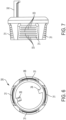
Fig. 2 illustrates a front view of thescrewdriver 10. As shown inFig. 2 , there are four light emitting diodes (LEDs) 71 mounted on a printed circuit board (PCB) 70. TheLEDs 71 illuminate an area forward of thescrewdriver 10. TheLEDs 71 may be covered by a lens. Thelens 72 in the exemplary embodiment is transparent. The lens may be translucent, frosted, colored, curved, flat or other lens configurations. -
Fig. 3 is an exploded view of selected components of thescrewdriver 10.Fig. 4 is a plan view of a rear face of thePCB 70.Fig. 3 includes thebody portion 20,collar 30, a spring 38, anosepiece 40 and thePCB 70. As shown inFig. 3 , and again inFigs. 11 and 12 , thebody portion 20 includes receivingprojections collar 30 is received on the receivingprojections collar 30 is radially outside of the receivingprojections projections - The
collar 30 includes a plurality of recessedgripping portions 31 on its outer surface. Thecollar 30 also includes aprojection 32. Theprojection 32 projects forward partially through thenosepiece 40 and selectivelycontacts microswitches PCB 70. When theprojection 32 actuates themicroswitch 75 by depressing themicroswitch 75, thescrewdriver 10 is configured to rotate in reverse. When theprojection 32 actuates themicroswitch 76 by depressing themicroswitch 76, thescrewdriver 10 is configured to rotate in a forward direction, opposite the reverse direction. The exemplary embodiment uses microswitches. In other embodiments, there may be different types of actuators such as other types of switches. ThePCB 70 may also include anelectrical connector port 77 for connecting thePCB 70 to thebattery 90 and any controller, such as thecontroller 100 shown inFig. 13 . The various electrical components of thescrewdriver 10 may be electrically connected by wires or other electrical connectors and theconnector port 77 may be a wire harness connector. ThePCB 70 is mounted in thenosepiece 40. - As shown in, for example,
Fig. 4 , thePCB 70 has a flat 78. The flat 78 may help with placement of thePCB 70 in thenosepiece 40 to ensure that it is located at the correct rotational location. There may be one or more other flats or location portions that are configured to ensure that thePCB 70 is installed in the correct orientation. ThePCB 70 also includes acentral hole 79 that allows for transmission through to the output member. -
Fig. 5 illustratesmicroswitch 75. Themicroswitch 75 has amovable portion 65 that is moved to actuate themicroswitch 75. Themicroswitch 76 has the same configuration as themicroswitch 75 shown inFig. 5 . -
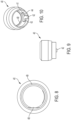
Fig. 6 illustrates a front view of thecollar 30 andFig. 7 illustrates a side view of thecollar 30. As shown, thecollar 30 includes the previously mentionedgripping portions 31. These grippingportions 31 are recessed and assist a user in gripping and moving thecollar 30. There may be various friction increasing features on thegripping portions 31. As shown inFig. 6 , thecollar 30 includes twoalignment projections 34, 35. Thesealignment projections 34 and 35 guide thecollar 30 as it slides and rotates. The alignment projection 35 may be aligned with theprojection 32 or integrally formed with theprojection 32. Thecollar 30 further includes aridge 36 for supporting a spring. The spring 38 (Fig. 3 ) sits between theridge 36 and a portion of thenosepiece 40 to bias thecollar 30 rearward. -
Fig. 8 is a front view of thenosepiece 40,Fig. 9 is a side view of thenose piece 40 andFig. 10 is a perspective view of thenosepiece 40. Thenosepiece 40, includes aflat portion 48 that corresponds with the flat 78 of thePCB 70 and allows proper placement of thePCB 70. ThePCB 70 generally sits on ashoulder 49 of thenosepiece 40 near a forward end of thenosepiece 40. - The
nosepiece 40 also includes a blockingpiece 41. As shown inFig. 10 , the blockingpiece 41 is generally "T" shaped. The blockingpiece 41 blocks advancement of thecollar 30. The blockingpiece 41 includes threeportions collar 30. In the central or lock-off position, thealignment portion 34 of the collar 30 (Fig. 6 ) is aligned with thecentral blocking portion 42. When thecollar 30 is in the lock-off position, if a user tries to slide thecollar 30 forward, thealignment portion 34 of thecollar 30 contacts thecentral blocking portion 42 and thecollar 30 is prevented from advancing forward. - The
collar 30 can be rotated clockwise to a forward operation position. In the forward operation position, thealignment portion 34 of the collar 30 (Fig. 6 ) is aligned with the forward blocking portion 43. When thecollar 30 is in the forward operation position, the user is able to slide thecollar 30 forward sufficient that theprojection 32 contacts themicroswitch 76 and thescrewdriver 10 is actuated so that theoutput member 50 rotates in the forward direction. Thealignment portion 34 of thecollar 30 contacts the forward blocking portion 43. The forward blocking portion 43 is located to allow thecollar 30 to advance sufficient for actuation of themicroswitch 76, but prevents thecollar 30 from advancing too far, so as to avoid damage to themicroswitch 76 orPCB 70. - The
collar 30 can be rotated counter-clockwise to a reverse operation position. In the reverse operation position, thealignment portion 34 of the collar 30 (Fig. 6 ) is aligned with thereverse blocking portion 44. When thecollar 30 is in the reverse position, the user is able to slide thecollar 30 forward sufficient that theprojection 32 contacts themicroswitch 75 and thescrewdriver 10 is actuated so that theoutput member 50 rotates in the reverse direction. Thealignment portion 34 of thecollar 30 contacts thereverse blocking portion 44. Thereverse blocking portion 44 is located to allow thecollar 30 to advance sufficient for actuation of themicroswitch 75, but prevents thecollar 30 from advancing too far, so as to avoid damage to themicroswitch 75 orPCB 70. -
Fig. 11 is a side view of thebody portion 20 andFig. 12 is a front view of thebody portion 20. As previously discussed, thecollar 30 fits over the receivingprojections Figs. 3 and11 , the receivingprojections grooves collar 30 may have internal projections which selectively fit into thegrooves collar 30 is rotated to the lock-off, forward and reverse positions so that thecollar 30 can be rotated to the appropriate position. That is, thecollar 30 will be lightly secured in a lock-off position so that a user may easily rotate and keep it in the lock-off position. Thegrooves collar 30 so that the detents may move out of the grooves.Alignment projections 34, 35 may contact ends of theprojections collar 30 relative to the body. That is, thecollar 30 may rotate only as thealignment projection 34 rotates from contacting one radial end ofprojection 21 to contacting a facing radial end ofprojection 22. The alignment projection 35 may operate similarly. - In other embodiments, the collar may have grooves and the body portion include detents. In other embodiments, the receiving
projections collar 30 thecollar 30 may have corresponding grooves, rails, detents and other features to facilitate the movement. - In some embodiments, the
body portion 20 may also house a transmission connected to an output of the motor. Wires and various other electrical connectors as are known in the art may be used to connect the various components of thescrewdriver 10. Thescrewdriver 10 may also include additional circuit boards including one or more controller, memory, transmitter, receiver or other electrical components. As discussed above, although the exemplary embodiment has been described with respect to a screwdriver, exemplary embodiments of other power tools are also contemplated. -
Fig. 13 is an explanatory circuit diagram for thescrewdriver 10. As shown, themotor 80,battery 90,rotary dial 60 andmicroswitches controller 100, which may be amicroprocessor 100. Acurrent sensor 65 may also be connected to themicroprocessor 100. Thecurrent sensor 65 may include a resistor and may measure a motor current. Since motor current is proportional to torque, the measure of motor current by thecurrent sensor 65 may be used to provide the torque limits mentioned above. - Although described by way of exemplary embodiments, it is understood that the words which have been used herein are words of description. Although the description provided above provides detail for the purpose of illustration based on what is currently considered to be the most practical and preferred embodiments, it is to be understood that such detail is solely for that purpose and that the disclosure is not limited to the expressly disclosed embodiments, but, on the contrary, is intended to cover modifications and equivalent arrangements that are within the scope of the appended claims
- It is to be understood that the present disclosure contemplates that, to the extent possible, one or more features of any embodiment or aspect can be combined or exchanged with one or more features of any other embodiment or aspect.
Claims (15)
- A power tool, comprising:a body;a motor housed in the body;a power source, preferably a battery, housed in the body;an output member configured to be selectively driven by the motor; andan actuation collar on the body, configured to actuate the power tool;wherein the actuation collar is rotatable relative to the body between a forward operation position and a reverse operation position;wherein in the forward operation position, the actuation collar is slidable in a forward direction towards the output member and the power tool is actuated to drive the output member in forward rotation; andwherein in the reverse operation position, the actuation collar is slidable in the forward direction towards the output member and the power tool is actuated to drive the output member in reverse rotation.
- A power tool according to claim 1, wherein actuation of the power tool comprises actuation of the motor to drive the output member.
- A power tool according to claim 1 or claim 2, wherein the actuation collar is biased away from the forward direction, preferably to a rearward position in which the motor is not actuated.
- A power tool according to any preceding claim, wherein the power tool further comprises a forward operation actuator and a reverse operation actuator; preferably wherein the forward operation actuator is actuated when the actuation collar is slid forward when in the forward operation position and/or the reverse operation actuator is actuated when the actuation collar is slid forward when in the reverse operation position.
- A power tool according to claim 4, wherein the forward operation actuator and the reverse operation actuator are microswitches.
- A power tool according to any preceding claim, further comprising a nosepiece between the body and the output member.
- A power tool according to claim 6, further comprising a circuit board disposed in the nosepiece.
- A power tool according to claim 7 when dependent upon claim 4 or any claim dependent thereon, further comprising at least one said actuator, preferably both said actuators, mounted on the circuit board.
- A power tool according to any preceding claim, wherein the collar is rotatable clockwise from the reverse operation position to the forward operation position, and the collar is rotatable counter-clockwise from the forward operation position to the reverse operation position.
- A power tool according to claim 9, wherein the actuation collar is also rotatable to a central lock-off position between the forward operation position and the reverse operation position.
- A power tool according to claim 10, wherein, when the actuation collar is in the lock-off position it is blocked from being slid forward.
- A power tool according to any preceding claim, wherein the tool is a rotary tool and the output member comprises a rotary tool chuck or other rotary tool holder for holding rotary tool accessories.
- A power tool according to claim 12, wherein the collar and the output member are coaxially rotatable.
- A power tool according to any preceding claim, wherein forward rotation of the output member is clockwise, and reverse rotation of the output member is counter-clockwise.
- A power tool according to any preceding claim, comprising a screwdriver, preferably wherein forward rotation of the output member is configured to drive a screw into a workpiece, and reverse rotation of the output member is configured to unscrew a screw.
Applications Claiming Priority (1)
| Application Number | Priority Date | Filing Date | Title |
|---|---|---|---|
| US17/653,896 US12576487B2 (en) | 2022-03-08 | 2022-03-08 | Power tool |
Publications (1)
| Publication Number | Publication Date |
|---|---|
| EP4257298A1 true EP4257298A1 (en) | 2023-10-11 |
Family
ID=85704615
Family Applications (1)
| Application Number | Title | Priority Date | Filing Date |
|---|---|---|---|
| EP23159807.9A Pending EP4257298A1 (en) | 2022-03-08 | 2023-03-03 | Power tool |
Country Status (2)
| Country | Link |
|---|---|
| US (1) | US12576487B2 (en) |
| EP (1) | EP4257298A1 (en) |
Families Citing this family (1)
| Publication number | Priority date | Publication date | Assignee | Title |
|---|---|---|---|---|
| USD1088786S1 (en) * | 2023-09-07 | 2025-08-19 | Stanley Black & Decker, Inc. | Screwdriver |
Citations (3)
| Publication number | Priority date | Publication date | Assignee | Title |
|---|---|---|---|---|
| US20130161039A1 (en) * | 2011-06-27 | 2013-06-27 | Robert Bosch Gmbh | Handheld Power Tool, in particular a Power Drill or Screwdriver |
| WO2019105097A1 (en) * | 2017-11-29 | 2019-06-06 | 苏州多维思智能科技有限公司 | Precise electric screwdriver |
| EP4049793A1 (en) * | 2021-02-25 | 2022-08-31 | Black & Decker, Inc. | Powered wrench |
Family Cites Families (32)
| Publication number | Priority date | Publication date | Assignee | Title |
|---|---|---|---|---|
| DE3103286A1 (en) | 1981-01-31 | 1982-08-12 | Kress-elektrik GmbH & Co, Elektromotorenfabrik, 7457 Bisingen | Electrical hand-held machine tool for screwing, drilling and possibly hammer-drilling |
| US4523116A (en) | 1983-03-31 | 1985-06-11 | Black & Decker, Inc. | Electrical connection system for motors |
| US4587384A (en) | 1984-07-12 | 1986-05-06 | Black & Decker, Inc. | Sub-assembly for electric motor including reversing switch |
| US4581499A (en) | 1984-07-12 | 1986-04-08 | Black & Decker, Inc. | Switch limit assembly |
| US4678871A (en) | 1985-07-22 | 1987-07-07 | Skil Corporation | Reversing switch for rechargeable hand tool |
| US4772765A (en) | 1987-02-12 | 1988-09-20 | Black & Decker Inc. | Combined on/off and reversing switch and electric device therewith |
| EP0408986B1 (en) | 1989-07-15 | 1995-01-18 | Kress-elektrik GmbH + Co. Elektromotorenfabrik | Switch device for electrical change-over switching of electric tools |
| US5154242A (en) | 1990-08-28 | 1992-10-13 | Matsushita Electric Works, Ltd. | Power tools with multi-stage tightening torque control |
| US5089729A (en) | 1991-03-14 | 1992-02-18 | Black & Decker Inc. | Power tool with brush shifting and reversing switch assembly |
| CN2145907Y (en) * | 1992-09-02 | 1993-11-10 | 湖北省机械化养鱼开发公司 | Multipurpose portable electric torch |
| US5251706A (en) | 1992-12-03 | 1993-10-12 | Jack Evans | Ratchet drive tool with manual and non-manual power actuation |
| US6424799B1 (en) | 1993-07-06 | 2002-07-23 | Black & Decker Inc. | Electrical power tool having a motor control circuit for providing control over the torque output of the power tool |
| US5440215A (en) | 1993-07-06 | 1995-08-08 | Black & Decker Inc. | Electrical power tool having a motor control circuit for increasing the effective torque output of the power tool |
| GB9320181D0 (en) | 1993-09-30 | 1993-11-17 | Black & Decker Inc | Improvements in and relating to power tools |
| US6479958B1 (en) | 1995-01-06 | 2002-11-12 | Black & Decker Inc. | Anti-kickback and breakthrough torque control for power tool |
| US5550416A (en) | 1995-02-09 | 1996-08-27 | Fanchang; We C. | Control mechanism of revolving speed of an electric tool |
| US5955802A (en) | 1997-12-19 | 1999-09-21 | Black & Decker Inc. | Reversing mechanism for electric motors |
| US6199642B1 (en) | 1999-07-06 | 2001-03-13 | Snap-On Tools Company | Reversible ratcheting power tool with synchronized motor and ratchet control |
| DE10337260A1 (en) | 2003-08-18 | 2005-03-10 | Bosch Gmbh Robert | Operating module for a power tool |
| US7836968B2 (en) | 2006-03-24 | 2010-11-23 | The Stanley Works | Power tool with improved start actuator |
| DE102007038358A1 (en) | 2007-08-14 | 2009-02-26 | Wisap Gesellschaft für wissenschaftlichen Apparatebau mbH | Device for driving instruments and tools and their use |
| JP5026890B2 (en) | 2007-08-27 | 2012-09-19 | 株式会社マキタ | Electric tool forward / reverse switching device |
| US7721631B2 (en) * | 2007-11-05 | 2010-05-25 | The Boeing Company | Combined wrench and marking system |
| DE102008040096A1 (en) | 2008-07-02 | 2010-01-07 | Robert Bosch Gmbh | Hand-guided electric machine tool i.e. battery-driven screw driver, operating method, involves operating electric motor by applying motor voltage, and limiting motor current to current value that depends on information about maximum torque |
| JP5262701B2 (en) | 2008-12-26 | 2013-08-14 | オムロン株式会社 | Power tool switch |
| DE102011014543B4 (en) | 2011-03-19 | 2019-05-23 | Richard Wolf Gmbh | Medical instrument |
| US8716962B2 (en) | 2011-11-10 | 2014-05-06 | Snap-On Incorporated | Variable speed trigger mechanism |
| JP6090581B2 (en) | 2013-09-28 | 2017-03-08 | 日立工機株式会社 | Electric tool |
| DE102016206050A1 (en) | 2016-04-12 | 2017-10-12 | Robert Bosch Gmbh | Hand tool with an electronic torque limiting unit |
| WO2018228825A1 (en) | 2017-06-12 | 2018-12-20 | Atlas Copco Industrial Technique Ab | Power wrench with angle drive |
| EP3638458B1 (en) | 2017-06-12 | 2024-08-07 | Atlas Copco Industrial Technique AB | Power wrench with adjustable trigger position |
| DE102019213720A1 (en) * | 2019-09-10 | 2021-03-11 | Robert Bosch Gmbh | Hand machine tool and method for operating the hand machine tool |
-
2022
- 2022-03-08 US US17/653,896 patent/US12576487B2/en active Active
-
2023
- 2023-03-03 EP EP23159807.9A patent/EP4257298A1/en active Pending
Patent Citations (3)
| Publication number | Priority date | Publication date | Assignee | Title |
|---|---|---|---|---|
| US20130161039A1 (en) * | 2011-06-27 | 2013-06-27 | Robert Bosch Gmbh | Handheld Power Tool, in particular a Power Drill or Screwdriver |
| WO2019105097A1 (en) * | 2017-11-29 | 2019-06-06 | 苏州多维思智能科技有限公司 | Precise electric screwdriver |
| EP4049793A1 (en) * | 2021-02-25 | 2022-08-31 | Black & Decker, Inc. | Powered wrench |
Also Published As
| Publication number | Publication date |
|---|---|
| US12576487B2 (en) | 2026-03-17 |
| US20230286117A1 (en) | 2023-09-14 |
Similar Documents
| Publication | Publication Date | Title |
|---|---|---|
| US6199642B1 (en) | Reversible ratcheting power tool with synchronized motor and ratchet control | |
| CN108406663B (en) | Electric tool | |
| US10894310B2 (en) | Power tool having interchangeable tool heads with an independent accessory switch | |
| EP2090399B1 (en) | Electrical power tool with an operating element of light transmissive material and an indicator device | |
| EP2223783B1 (en) | Light for a power tool and method of illuminating a workpiece | |
| US9352458B2 (en) | Power tool with light for illuminating workpiece | |
| US8665058B2 (en) | Variable speed toggle trigger | |
| US20060220612A1 (en) | Modular panel for a power tool | |
| US12318907B2 (en) | Hand-held power tool | |
| EP2094450A2 (en) | Modular power hand tool | |
| JP7031277B2 (en) | Electrical equipment | |
| CN201320752Y (en) | Electric tool | |
| US12576487B2 (en) | Power tool | |
| TWI816318B (en) | Tool and direction selector mechanism used in tool | |
| AU2022202579A1 (en) | Ratchet with toggle trigger | |
| JP2022042351A (en) | Electric tool | |
| CN113787484A (en) | Operation method of electric screwdriver | |
| GB2372471A (en) | Power tool system | |
| HK40074477A (en) | Non-contact direction selector mechanism | |
| EP1302283A2 (en) | Powered hand-tool | |
| CA2507475A1 (en) | Modular panel for a power tool | |
| GB2380963A (en) | Powered hand-tool actuated by pressing against a workpiece |
Legal Events
| Date | Code | Title | Description |
|---|---|---|---|
| PUAI | Public reference made under article 153(3) epc to a published international application that has entered the european phase |
Free format text: ORIGINAL CODE: 0009012 |
|
| STAA | Information on the status of an ep patent application or granted ep patent |
Free format text: STATUS: THE APPLICATION HAS BEEN PUBLISHED |
|
| AK | Designated contracting states |
Kind code of ref document: A1 Designated state(s): AL AT BE BG CH CY CZ DE DK EE ES FI FR GB GR HR HU IE IS IT LI LT LU LV MC ME MK MT NL NO PL PT RO RS SE SI SK SM TR |
|
| STAA | Information on the status of an ep patent application or granted ep patent |
Free format text: STATUS: REQUEST FOR EXAMINATION WAS MADE |
|
| 17P | Request for examination filed |
Effective date: 20240410 |
|
| RBV | Designated contracting states (corrected) |
Designated state(s): AL AT BE BG CH CY CZ DE DK EE ES FI FR GB GR HR HU IE IS IT LI LT LU LV MC ME MK MT NL NO PL PT RO RS SE SI SK SM TR |