EP4257005B1 - Abnehmbare brieftasche für mobiltelefon - Google Patents
Abnehmbare brieftasche für mobiltelefon Download PDFInfo
- Publication number
- EP4257005B1 EP4257005B1 EP22180107.9A EP22180107A EP4257005B1 EP 4257005 B1 EP4257005 B1 EP 4257005B1 EP 22180107 A EP22180107 A EP 22180107A EP 4257005 B1 EP4257005 B1 EP 4257005B1
- Authority
- EP
- European Patent Office
- Prior art keywords
- rigid body
- phone
- cavity
- phone wallet
- panel
- Prior art date
- Legal status (The legal status is an assumption and is not a legal conclusion. Google has not performed a legal analysis and makes no representation as to the accuracy of the status listed.)
- Active
Links
Images


Classifications
-
- H—ELECTRICITY
- H04—ELECTRIC COMMUNICATION TECHNIQUE
- H04M—TELEPHONIC COMMUNICATION
- H04M1/00—Substation equipment, e.g. for use by subscribers
- H04M1/02—Constructional features of telephone sets
- H04M1/21—Combinations with auxiliary equipment, e.g. with clocks or memoranda pads
-
- A—HUMAN NECESSITIES
- A45—HAND OR TRAVELLING ARTICLES
- A45C—PURSES; LUGGAGE; HAND CARRIED BAGS
- A45C11/00—Receptacles for purposes not provided for in groups A45C1/00-A45C9/00
- A45C11/18—Ticket-holders or the like
- A45C11/182—Credit card holders
-
- A—HUMAN NECESSITIES
- A45—HAND OR TRAVELLING ARTICLES
- A45C—PURSES; LUGGAGE; HAND CARRIED BAGS
- A45C1/00—Purses; Money-bags; Wallets
- A45C1/02—Purses
-
- A—HUMAN NECESSITIES
- A45—HAND OR TRAVELLING ARTICLES
- A45C—PURSES; LUGGAGE; HAND CARRIED BAGS
- A45C13/00—Details; Accessories
- A45C13/005—Hinges
-
- A—HUMAN NECESSITIES
- A45—HAND OR TRAVELLING ARTICLES
- A45C—PURSES; LUGGAGE; HAND CARRIED BAGS
- A45C13/00—Details; Accessories
- A45C13/10—Arrangement of fasteners
- A45C13/1069—Arrangement of fasteners magnetic
-
- A—HUMAN NECESSITIES
- A45—HAND OR TRAVELLING ARTICLES
- A45C—PURSES; LUGGAGE; HAND CARRIED BAGS
- A45C15/00—Purses, bags, luggage or other receptacles covered by groups A45C1/00 - A45C11/00, combined with other objects or articles
-
- H—ELECTRICITY
- H04—ELECTRIC COMMUNICATION TECHNIQUE
- H04M—TELEPHONIC COMMUNICATION
- H04M1/00—Substation equipment, e.g. for use by subscribers
- H04M1/02—Constructional features of telephone sets
- H04M1/04—Supports for telephone transmitters or receivers
-
- A—HUMAN NECESSITIES
- A45—HAND OR TRAVELLING ARTICLES
- A45C—PURSES; LUGGAGE; HAND CARRIED BAGS
- A45C11/00—Receptacles for purposes not provided for in groups A45C1/00-A45C9/00
- A45C11/002—Receptacles for purposes not provided for in groups A45C1/00-A45C9/00 for storing portable handheld communication devices, e.g. pagers or smart phones
-
- A—HUMAN NECESSITIES
- A45—HAND OR TRAVELLING ARTICLES
- A45C—PURSES; LUGGAGE; HAND CARRIED BAGS
- A45C2200/00—Details not otherwise provided for in A45C
- A45C2200/15—Articles convertible into a stand, e.g. for displaying purposes
Definitions
- the present invention relates generally to wallets that attach to electronic devices. More particularly, the present invention relates to a phone wallet that unobtrusively and easily detaches and reattaches to an electronic device while concealing an opening to the wallet and while providing a support stand when attached to the phone. The present invention further relates to a non-intrusive mobile phone protective case having a pocket adapted for receiving the detachable phone wallet therein. The phone wallet is easily removed to allowing for wireless charging of the mobile device without removing the casing.
- a detachable phone wallet apparatus for coupling to an electronic device, the phone wallet apparatus comprising: a rigid body having a cavity formed therein; a hinged panel having a first end portion fixed to an outer surface of the rigid body and a second free end portion that is adapted to extend over and cover a first open end of the cavity; alignment magnets; panel magnets associated with one of the hinged panel and the rigid body; and the hinged panel including a plurality of hinged folds.
- Embodiments according to aspects of the present invention provide a detachable phone wallet that quickly magnetically couples and decouples with a smart phone. These embodiments further provide a phone wallet that has a hinged storage compartment cover that may be used as a stand when coupled to a phone. In certain embodiments according to aspects of the invention the detachable phone wallet fits within a pocket formed in a protective covering that protects the phone by encompasses the sides and back of the smart phone. The multi hinged panel or cavity may be utilized to conceal the storage compartment and may also be altered to prop up or stand the electronic device at a desired angle. A further aspect of the invention allows a wireless charger to be linked to phone through the pocket of the protective casing.
- the detachable phone wallet in accordance with aspects of the present invention includes a rigid body having a cavity formed therein and a hinged panel that covers an open end of the cavity.
- the hinged panel has a first end portion fixed to an outer surface of the rigid body and a second free end portion that is adapted to extend over and cover the open end of the cavity.
- the cavity terminates in the rigid body at a base portion of the rigid body, thereby forming a second closed end of the cavity.
- the base portion includes a backing portion that forms an exterior of the rigid body. Alignment magnets are sandwiched between the base portion and backing portion of the closed end of the cavity of the rigid body.
- the base portion and backing portion may be constructed as layers attached to the remaining portion of the rigid body or may be manufactured integral with the rigid body.
- the alignment magnets are embedded during the manufacture of the rigid body.
- Panel magnets are associated with either or both of the hinged panel and the rigid body to provide fixation of the hinged panel when covering the cavity.
- the hinged panel further includes a plurality of hinged folds.
- the detachable phone wallet may further include ferromagnetic metal strips associated with the hinged panel that attract to panel magnets positioned on the rigid body.
- hinged folds may be defined by a plurality of hinged joints.
- the open end of the cavity may include flanges extending from the rigid body that provides additional support to the hinged panel when covering the cavity.
- ramps may be formed on the cavity sidewalls to facilitate insertion and removal of credit and ID cards relative to the cavity.
- the phone wallet may insert into a pocket formed in a protective casing.
- the casing has a pliable body and a rim extending outward from the pliable body, wherein the rim of the pliable body is adapted for engaging sides of an electronic device.
- the pliable quality is considered relative to the wallet's rigid body.
- the pliable body is considered pliable if it is able to be manipulated enough to slip over the sides of a phone and encase the phone sides.
- an embodiment of the invention includes a rigid body, a panel cover, alignment magnets, panel cover magnets, and a phone protective casing.
- the rigid body has a cavity formed therein such that the rigid body has an open end or open front and a closed end or closed back side.
- the closed end or back side of the rigid body is comprised of a base portion or layer and a backing portion or layer.
- the alignment magnets are sandwiched between the base portion and backing portion of the rigid body and the backing portion forms an exterior of the rigid body.
- the backing portion and base portion may be layers or films applied to the rigid body or may be integral with the rigid body.
- the hinge panel has a first end portion that is fixed to an outer surface of the rigid body and further has a second free end portion that is adapted to extend over and cover the open end of the cavity.
- the protective phone casing extends outward in the same plane as the back face of the rigid body and includes a rim extending orthogonally about a perimeter of the casing. The dimensions of the planar casing and rim are such so that sides of a phone may be encompassed, engaged, and encased by the rim.
- the protective casing further includes a pocket that is dimensioned and adapted to receive and couple the rigid body within the pocket.
- the detachable phone wallet may further include metal strips associated with the hinged panel and magnets associated with the rigid body. In this manner the magnets may hold the hinge panel in place when the panel is covering the open cavity of the rigid body.
- the rigid body may further include flanges that block outer access to a portion of the cavity and provide support to the hinge panel.
- the protective casing may include one or more apertures extending through the casing that are dimensioned and positioned to allow access to control ports or other features of the mobile device.
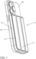
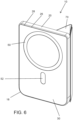
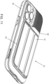
- a slender and compact detachable phone wallet 10 is provided that minimizes the bulkiness and weight of a larger wallet and may also include a phone casing 84 that encompasses the back and sides of a mobile phone to offer impact protection and additional versatility.
- the detachable phone wallet 10 for a mobile electronic device 96 is configured to be user easily removed and reattached, allowing a user to wirelessly charge the phone battery without removing the casing from the phone.
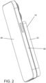
- Figures 1-2 illustrate an exemplary mobile electronic device 96 magnetically coupled with an embodiment of the detachable phone wallet 10 of the present invention.
- the width between the sides 20 of the detachable phone wallet is dimensioned to be equal to or less than the width between sides 98 of the mobile device 98.
- the length of the phone wallet is sized such that when it is attached to a mobile device it does not block or interfere with the phone accessories such as camera lens.
- the thickness is dimensioned to provide storage capacity within the wallet while keeping the overall thickness of the wallet to be relatively thin. In a preferred embodiment the thickness of the wallet 10 is equal to or less than the mobile device 96 to which it attaches.
- the detachable phone wallet 10 is adhered to the mobile electronic device 96 by means of magnetic attraction.
- the phone wallet 10 includes a rigid body 18, a panel cover 70, alignment magnets 50 and 52, and panel cover magnets 56.
- the rigid body 18 has a cavity 22 formed into the rigid body 18 such that the rigid body 18 has an open end or open front 32 and a closed end or closed back side 34.
- the closed end or back side 34 of the rigid body 18 is comprised of a base portion or layer 26 and a backing portion or outer layer 28.
- the outer surface 30 or back side of the rigid body 18 contacts the back surface of the phone 96 when magnetically coupled to the phone.
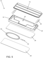
- Figures 5-7 further illustrate the orientation of the alignment magnets 50 and 52 relative to the rigid body 18.
- the alignment magnets 50 and 52 are sandwiched between the base portion 26 and backing portion 28 of the rigid body 18.
- the backing portion 28 forms an exterior of the rigid body 18 is relatively thin such that the strength of the magnetic fields from alignment magnets 50 and 52 are not significantly reduced.
- the backing portion 28 and base portion 26 may be layers or films applied to the rigid body or may be formed integral with the rigid body 18.
- the hinge panel or panel cover 70 has a first end portion 72 that is fixed to an outer surface 24 of the rigid body 18 and further has a second free end 76 portion that is adapted to extend over and cover the open end 32 of the cavity 22.
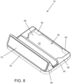
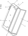
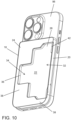
- Figures 8-10 further illustrate the cavity or compartment 22 formed in the rigid body 18 of the phone wallet 10.
- the cavity 22 terminates within the rigid body 18 at a base portion 26 of the rigid body, thereby forming the second closed end 34 of the cavity 22.
- the cavity includes sides 36 that are dimensioned such that the distance between opposing sides is sufficient to allow insertion of an ID or credit card between the sides.
- a flange 38 extends out and over the cavity 22 to further define the outer surface 24 of the rigid body 18.
- the flange 38 further supports the hinge panel 70 and retains items placed within the cavity or compartment 22 (see Figure 10 ).
- the front or exposed side of the cavity 22 includes sloped or ramped sides 42. Credit cards or ID's slide up and down the ramp 42 assisting the user to insert and remove cards from the compartment.
- Pockets 44 are formed in a top surface of the rigid body and are adapted to receive panel magnets 56.
- the hinge panel 70 includes panel joints 74 and panel sections 80.
- the panel sections may include metal strips or magnetic strips 80.
- the panel magnets 56 and hinge magnets or metal attract towards each other to help retain the panel cover over the cavity 22 thereby concealing the compartment.
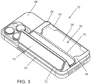
- the user may further orient the hinge panel 70 to provide a stand for the mobile device 96 (see Figure 3 and Figures 8-9 ).
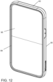
- the detachable wallet apparatus 10 (illustrated in Figures 11-20 ) generally includes a rigid body 18 and phone casing 84.
- the phone casing includes a pliable body 86 and a pocket 88 formed in the casing.
- the pocket includes sidewalls 90 that are adapted for receiving and engaging the rigid body 18.
- An outer rim portion 92 of the pliable body 86 overlaps at least the sides 98 of the mobile device 96 to retain the mobile device 96.
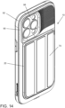
- Figures 13-15 further illustrate how the casing 84 and rigid body 18 integrate together to provide a phone wallet that may also act as a protective casing for a phone.
- the pliable body 86 of the protective phone casing 84 extends outward from the pocket 88 in the same plane as the back face of the rigid body 18 and includes a rim 92 extending orthogonally about a perimeter of the pliable body.
- the dimensions of the planar casing 84 and rim 92 are such so that sides of a phone may be encompassed, engaged, and encased by the rim 92.
- the casing 84 is pliable in the sense that the rim 92 may be deformed or bent to slip over the sides of a phone and encase the phone sides.
- Apertures 94 may extend through various locations about the casing 84, pliable body 86, and rim 92. The apertures 94 align with and correspond with various features of the electronic device.
- the rigid body 18 has a cavity 22 formed into the rigid body 18 such that the rigid body 18 has an open end or open front 32 and a closed end or closed back side 34.
- the closed end or back side 34 of the rigid body 18 is comprised of a base portion or layer 26 and a backing portion or outer layer 28.
- the outer surface 30 or back side of the rigid body 18 contacts the back surface of the phone 96 when magnetically coupled to the phone.
- Figure 13 illustrates the orientation of the alignment magnets 50 and 52 relative to the rigid body 18.
- the alignment magnets 50 and 52 are sandwiched between the base portion 26 and backing portion 28 of the rigid body 18.
- the backing portion 28 forms an exterior of the rigid body 18 is relatively thin such that the strength of the magnetic fields from alignment magnets 50 and 52 are not significantly reduced.
- the backing portion 28 and base portion 26 may be layers or films applied to the rigid body or may be formed integral with the rigid body 18.
- the hinge panel or panel cover 70 has a first end portion 72 that is fixed to an outer surface 24 of the rigid body 18 and further has a second free end 76 portion that is adapted to extend over and cover the open end 32 of the cavity 22.
- Figure 15 further illustrates the cavity or compartment 22 formed in the rigid body 18 of the phone wallet 10.
- the cavity 22 terminates within the rigid body 18 at a base portion 26 of the rigid body, thereby forming the second closed end 34 of the cavity 22.
- the cavity includes sides 36 that are dimensioned such that the distance between opposing sides is sufficient to allow insertion of an ID or credit card between the sides.
- a flange 38 extends out and over the cavity 22 to further define the outer surface 24 of the rigid body 18.
- the flange 38 further supports the hinge panel 70 and retains items placed within the cavity or compartment 22.
- the front or exposed side of the cavity 22 includes sloped or ramped sides 42. Credit cards or ID's slide up and down the ramp 42 assisting the user to insert and remove cards from the compartment.
- Pockets 44 are formed in a top surface of the rigid body and are adapted to receive panel magnets 56.
- the hinge panel 70 includes panel joints 74 and panel sections 80.
- the panel sections may include metal strips or magnetic strips 80.
- the panel magnets 56 and hinge magnets or metal attract towards each other to help retain the panel cover over the cavity 22 thereby concealing the compartment.
- the metal strips or magnets cooperate with magnets 56 to fix the panel in a desired position relative to rigid body 18.
- the panel 70 may be formed integral with the rigid body 18, may be permanently attached to the rigid body 18 or may be removably attached to the rigid body 18.
- the hinged panel cover 70 may be oriented in several positions relative to the rigid body.
- the hinged panel 70 may be utilized to vary the angle of the display screen of the mobile device 96 when propped on a flat surface.
- the user may use the length of the panel or an end of the panel to prop the phone.
- the viewing angle may range from 15-45 degrees from vertical or from 20-25 degrees from a horizontal viewing angle.
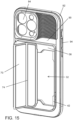
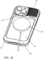
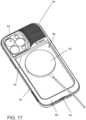
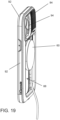
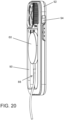
- Figures 16-20 further illustrate the casing 84 integrated with the rigid body 18 and the ability to wirelessly charge the batteries of the electronic device 96 without decoupling or removing the casing 84 from the electronic device.
- the casing 84 includes a planar pliable body 86.
- a pocket 88 is formed in the casing wherein the pocket has an inner sidewall 90 that is sized slightly larger than the perimeter of the rigid body.
- the rigid body nests within the pocket of the casing 84 and the magnets fix the rigid body within the pocket.
- To wirelessly charge the device the user simply removes the rigid body to expose the back side of the phone 96. The user then places charger 60 in contact with the phone 96.
- the alignment magnets 50 and 52 of the rigid body retain the rigid body and keep it from falling out of the pocket 88 formed in the casing 84.
Landscapes
- Engineering & Computer Science (AREA)
- Signal Processing (AREA)
- Telephone Set Structure (AREA)
Claims (8)
- Abnehmbare Brieftascheneinrichtung für ein Mobiltelefon (10) zum Koppeln an eine elektronische Vorrichtung (96), wobei die Brieftascheneinrichtung für ein Mobiltelefon umfasst:einen starren Korpus (18) mit einem darin gebildeten Hohlraum (22);eine schwenkbare Platte (70) mit einem ersten Endabschnitt (72), welcher an einer Außenfläche (24) des starren Korpus befestigt ist, und einem zweiten, freien Endabschnitt (76), welcher dazu adaptiert ist, sich über das erste, offene Ende (32) des Hohlraums zu erstrecken und diesen zu bedecken;einen Basisabschnitt (26) des starren Korpus, welcher ein zweites, geschlossenes Ende (34) des Hohlraums bildet;einen Stützabschnitt (28) des Basisabschnitts des starren Korpus, wobei der Stützabschnitt eine Außenseite des starren Korpus bildet;Ausrichtungsmagnete (50, 52), welche zwischen dem Basisabschnitt und dem Stützabschnitt des starren Korpus eingefügt sind;Plattenmagnete (56), welche mit einem der schwenkbaren Platte und dem starren Korpus verbunden sind; undwobei die schwenkbare Platte eine Vielzahl von Falzen beinhaltet.
- Brieftascheneinrichtung für ein Mobiltelefon (10) nach Anspruch 1, weiter Metallstreifen beinhaltend, welche mit der schwenkbaren Platte (70) verbunden sind.
- Brieftascheneinrichtung für ein Mobiltelefon (10) nach Anspruch 1 oder Anspruch 2, wobei die schwenkbaren Falze durch eine Vielzahl von Scharniergelenken definiert sind.
- Brieftascheneinrichtung für ein Mobiltelefon (10) nach einem der vorstehenden Ansprüche, weiter Flansche (38) beinhaltend, welche äußeren Zugriff auf einen Abschnitt des Hohlraums (22) blockieren.
- Brieftascheneinrichtung für ein Mobiltelefon (10) nach Anspruch 4, weiter eine abgeschrägte Seite (42) des Hohlraums (22) beinhaltend.
- Brieftascheneinrichtung für ein Mobiltelefon (10) nach Anspruch 5, wobei die abgeschrägte Seite (42) auf zumindest einem von dem Basisabschnitt (26) oder gegenüberliegenden Seiten des Hohlraums gebildet ist.
- Brieftascheneinrichtung für ein Mobiltelefon (10) nach einem der vorstehenden Ansprüche, weiter ein Gehäuse (84) mit einem biegsamen Korpus (86) beinhaltend, wobei der biegsame Korpus einen Rand (92) aufweist, welcher sich rund um einen Umfang des biegsamen Korpus erstreckt, wobei der Rand des biegsamen Korpus dazu adaptiert ist, in Seiten einer elektronischen Vorrichtung (96) einzugreifen, und weiter eine Tasche (88) aufweist, welche sich durch den biegsamen Korpus erstreckt, wobei die Tasche dazu adaptiert ist, den starren Korpus darin aufzunehmen.
- Brieftascheneinrichtung für ein Mobiltelefon (10) nach Anspruch 7, wobei das Gehäuse (84) weiter Öffnungen (94) beinhaltet, welche sich durch den biegsamen Korpus (86) erstrecken und so orientiert sind, dass sie mit Merkmalen der elektronischen Vorrichtung (96) ausgerichtet sind.
Applications Claiming Priority (1)
| Application Number | Priority Date | Filing Date | Title |
|---|---|---|---|
| US17/712,581 US12089706B1 (en) | 2022-04-04 | 2022-04-04 | Detachable phone wallet |
Publications (3)
| Publication Number | Publication Date |
|---|---|
| EP4257005A1 EP4257005A1 (de) | 2023-10-11 |
| EP4257005B1 true EP4257005B1 (de) | 2024-07-31 |
| EP4257005C0 EP4257005C0 (de) | 2024-07-31 |
Family
ID=82163490
Family Applications (1)
| Application Number | Title | Priority Date | Filing Date |
|---|---|---|---|
| EP22180107.9A Active EP4257005B1 (de) | 2022-04-04 | 2022-06-21 | Abnehmbare brieftasche für mobiltelefon |
Country Status (3)
| Country | Link |
|---|---|
| US (1) | US12089706B1 (de) |
| EP (1) | EP4257005B1 (de) |
| CN (1) | CN116939082A (de) |
Families Citing this family (5)
| Publication number | Priority date | Publication date | Assignee | Title |
|---|---|---|---|---|
| USD1095018S1 (en) * | 2022-11-11 | 2025-09-30 | Electronic Silk Road (Shenzhen) Tech Co., Ltd. | Magnetic card sleeve |
| USD1000111S1 (en) * | 2023-05-11 | 2023-10-03 | elago CO. LTD | Card holder for smart phone |
| USD1109134S1 (en) * | 2024-07-10 | 2026-01-13 | Hamee Global Inc. | Cell phone case with card holder |
| US20260101925A1 (en) * | 2024-10-16 | 2026-04-16 | Dan Beal | Combination smoking caddy and phone support |
| KR102894974B1 (ko) * | 2025-02-14 | 2025-12-10 | 주식회사 모란카노코리아 | Ai 기반의 모바일 액세서리 온라인 커스터마이징 자동 주문용 반제품 액세서리 |
Family Cites Families (47)
| Publication number | Priority date | Publication date | Assignee | Title |
|---|---|---|---|---|
| DE20209610U1 (de) | 2001-11-03 | 2002-11-14 | Goros, Jean, 85540 Haar | Schutzhülle für mobile elektronische Kleingeräte |
| KR101366219B1 (ko) | 2008-09-09 | 2014-02-21 | 제로 크로마, 엘엘씨 | 지지대를 가진 전자 장치의 홀더 |
| US20100122756A1 (en) | 2008-11-14 | 2010-05-20 | Kip Longinotti-Buitoni | Protective covering for personal electronic device |
| US20110077061A1 (en) | 2009-07-03 | 2011-03-31 | Alex Danze | Cell phone or pda compact case |
| US9281858B2 (en) | 2014-01-03 | 2016-03-08 | Incipio, Llc | Co-molded multi-layered protective case for mobile device |
| US8418852B2 (en) | 2009-10-20 | 2013-04-16 | John T. Ziemba | Compartmentalized protective case for portable handheld electronic devices |
| US8989826B1 (en) | 2010-05-21 | 2015-03-24 | Linda Connolly | Cellular phone case and storage accessory |
| US20110294542A1 (en) | 2010-05-27 | 2011-12-01 | Edgy Angel Productions Llc | Cell phone cover with integrated mirror and flip shield |
| US8328008B2 (en) | 2010-08-10 | 2012-12-11 | Incase Designs Corp. | Case for electronic tablet |
| SG188344A1 (en) * | 2010-09-21 | 2013-04-30 | Speculative Product Design Llc | A case for enclosing a personal electronic device and card |
| MX2013004136A (es) | 2010-10-12 | 2013-08-21 | Treefrog Developments Inc | Alojamiento para encerrar un objeto. |
| EP2463747A3 (de) | 2010-12-11 | 2015-01-21 | SA Shuang | Gehäusevorrichtung für tragbare elektronische Vorrichtung |
| US8726952B2 (en) | 2010-12-29 | 2014-05-20 | Sunder G. Jambunathan | Wireless phone wallet |
| US8942773B2 (en) | 2011-07-11 | 2015-01-27 | Jenn Yaw J. Y. Enterprises Co., Ltd. | Protection case for electronic device |
| US8759675B2 (en) | 2011-09-07 | 2014-06-24 | Lakshman Rajeswaran | Dual purpose casing |
| US8504127B2 (en) | 2011-10-16 | 2013-08-06 | Matthew Timothy Altschul | Pocket case for mobile communications devices combined with carrying compartment for credit card sized items |
| US20130220847A1 (en) | 2012-01-17 | 2013-08-29 | Roy Roee FISHER | Multipurpose protective case for portable electronic device |
| US8967377B2 (en) | 2012-02-07 | 2015-03-03 | Ian F Lebauer | Protective case for portable electronic device with foldable lens cover and storage compartments |
| US9035872B2 (en) * | 2012-06-08 | 2015-05-19 | Apple Inc. | Detection system and method between accessory and electronic device |
| KR101329031B1 (ko) | 2012-08-30 | 2013-11-14 | 최택진 | 인출식 카드 수납구조를 갖는 휴대폰 케이스 |
| US9413412B2 (en) | 2012-08-30 | 2016-08-09 | Glenfield Gipson | Electronic device protective case and article carrying pouch |
| US20140091689A1 (en) * | 2012-09-28 | 2014-04-03 | E. Mishan & Sons, Inc. | Cover Having Wallet Feature for Electronic Devices |
| US20140128132A1 (en) | 2012-10-12 | 2014-05-08 | James L. Cox, III | Case with interchangeable back plates |
| TWM451788U (zh) | 2012-10-31 | 2013-04-21 | Chi Mei Comm Systems Inc | 可攜帶型電子裝置保護殼 |
| US9681719B2 (en) * | 2012-11-16 | 2017-06-20 | Jake Ehrlich | Mobile electronic device case wallet |
| US9644783B2 (en) | 2013-03-16 | 2017-05-09 | James A Rinner | Phone camera tablet bipod support system |
| KR101356236B1 (ko) | 2013-05-22 | 2014-02-03 | 김대인 | 카메라 노출이 가능하면서 스마트폰을 휴대가능한 장지갑. |
| US9124350B2 (en) | 2013-06-21 | 2015-09-01 | Francesco BIANCAMANO | Case for mobile device |
| US20150011265A1 (en) | 2013-07-05 | 2015-01-08 | James A. Walsh, JR. | Support Apparatus for Mobile Device |
| US9398793B2 (en) | 2013-11-14 | 2016-07-26 | Fiona Kotur Marin | Clutch case with outer mounting plate for holding a smartphone |
| US9049283B1 (en) | 2014-06-16 | 2015-06-02 | Spigen Korea Co., Ltd. | Case having a storage compartment for electronic devices |
| US20160014922A1 (en) | 2014-07-11 | 2016-01-14 | Fellowes, Inc. | Electronic device case with a combination card and item holder |
| USD831630S1 (en) | 2014-12-05 | 2018-10-23 | Catalyst Medium Four, Inc. | Cellular phone case |
| US20180006676A1 (en) * | 2015-05-08 | 2018-01-04 | Cesar Zavala | Protective case for electronic device with storage area |
| US10164468B2 (en) * | 2015-06-16 | 2018-12-25 | Otter Products, Llc | Protective cover with wireless charging feature |
| US10236928B2 (en) | 2016-01-04 | 2019-03-19 | Incipio, Llc | Molded mobile device case with storage compartment having hinged access |
| US9768822B1 (en) | 2016-07-11 | 2017-09-19 | Forever Holdings, Inc. | Smart phone carrying case with stand |
| KR200489109Y1 (ko) * | 2017-01-03 | 2019-05-02 | 주식회사 아이스픽 | 카드수납 가능한 휴대폰 케이스 |
| FR3061423B1 (fr) * | 2017-01-03 | 2020-10-23 | Ilyu | Ensemble comportant un brassard et une pochette pour smartphone |
| US10506857B2 (en) | 2017-01-04 | 2019-12-17 | Catalyst Medium Four, Inc. | Adhesive pocket for mobile phones |
| US11083264B2 (en) * | 2017-08-15 | 2021-08-10 | Under Armour, Inc. | Case for portable electronics device |
| US10511342B1 (en) * | 2018-09-12 | 2019-12-17 | Ispeaker Co., Ltd. | Cell phone case with card storage capability |
| GB2586810A (en) * | 2019-09-03 | 2021-03-10 | Mous Products Ltd | Case for mobile device |
| US12300837B2 (en) * | 2020-08-05 | 2025-05-13 | Apple Inc. | Magnetically attachable battery pack |
| US12040643B2 (en) * | 2020-08-05 | 2024-07-16 | Apple Inc. | Magnetically attachable charging devices |
| US11839279B2 (en) * | 2020-09-22 | 2023-12-12 | Apple Inc. | Magnetically attachable wallet |
| US11240365B1 (en) * | 2020-09-25 | 2022-02-01 | Apple Inc. | Dynamic user interface schemes for an electronic device based on detected accessory devices |
-
2022
- 2022-04-04 US US17/712,581 patent/US12089706B1/en active Active
- 2022-06-21 EP EP22180107.9A patent/EP4257005B1/de active Active
- 2022-07-11 CN CN202210809552.1A patent/CN116939082A/zh active Pending
Also Published As
| Publication number | Publication date |
|---|---|
| EP4257005A1 (de) | 2023-10-11 |
| CN116939082A (zh) | 2023-10-24 |
| US12089706B1 (en) | 2024-09-17 |
| EP4257005C0 (de) | 2024-07-31 |
Similar Documents
| Publication | Publication Date | Title |
|---|---|---|
| EP4257005B1 (de) | Abnehmbare brieftasche für mobiltelefon | |
| US9768822B1 (en) | Smart phone carrying case with stand | |
| US9413412B2 (en) | Electronic device protective case and article carrying pouch | |
| EP0893777B1 (de) | Datenkartengehäuse | |
| TW589852B (en) | Portable phone with embedded battery | |
| EP2463747A2 (de) | Gehäusevorrichtung für tragbare elektronische Vorrichtung | |
| US20130188122A1 (en) | Eyeglass storage system | |
| EP0893776A2 (de) | Ein Datenkartensteckverbinder | |
| US20100048268A1 (en) | Mobile device accessories and methods of attachment to mobile devices | |
| KR102423199B1 (ko) | 카드수납구조를 포함하는 접이식 휴대폰 케이스 | |
| US20140091689A1 (en) | Cover Having Wallet Feature for Electronic Devices | |
| US20210234569A1 (en) | Device case comprising track system and method of making and using the same | |
| US20030147208A1 (en) | Mobile devices having a mirror | |
| KR101419199B1 (ko) | 휴대폰용 케이스 | |
| KR20210110527A (ko) | 카드 및 지폐 수납구조를 포함하는 도어형 휴대폰 케이스 | |
| US9857837B1 (en) | Portable electronic device case | |
| KR20170002571U (ko) | 보조배터리 및 유에스비 케이블을 포함하는 휴대폰 케이스 | |
| KR200479106Y1 (ko) | 다용도 휴대폰 파우치 | |
| KR200472573Y1 (ko) | 지갑이 내장된 핸드폰 보호케이스 | |
| US20230026280A1 (en) | Device charging system | |
| KR20140005628U (ko) | 지갑이 부착된 이동통신단말기용 보호케이스 | |
| KR20160010778A (ko) | 지갑겸용 휴대단말기 보호케이스 | |
| KR200375089Y1 (ko) | 휴대용 단말기의 외장케이스 | |
| US20050190542A1 (en) | Case for handheld device | |
| WO2009059181A2 (en) | Case battery |
Legal Events
| Date | Code | Title | Description |
|---|---|---|---|
| PUAI | Public reference made under article 153(3) epc to a published international application that has entered the european phase |
Free format text: ORIGINAL CODE: 0009012 |
|
| STAA | Information on the status of an ep patent application or granted ep patent |
Free format text: STATUS: THE APPLICATION HAS BEEN PUBLISHED |
|
| AK | Designated contracting states |
Kind code of ref document: A1 Designated state(s): AL AT BE BG CH CY CZ DE DK EE ES FI FR GB GR HR HU IE IS IT LI LT LU LV MC MK MT NL NO PL PT RO RS SE SI SK SM TR |
|
| STAA | Information on the status of an ep patent application or granted ep patent |
Free format text: STATUS: REQUEST FOR EXAMINATION WAS MADE |
|
| 17P | Request for examination filed |
Effective date: 20231023 |
|
| RBV | Designated contracting states (corrected) |
Designated state(s): AL AT BE BG CH CY CZ DE DK EE ES FI FR GB GR HR HU IE IS IT LI LT LU LV MC MK MT NL NO PL PT RO RS SE SI SK SM TR |
|
| GRAP | Despatch of communication of intention to grant a patent |
Free format text: ORIGINAL CODE: EPIDOSNIGR1 |
|
| STAA | Information on the status of an ep patent application or granted ep patent |
Free format text: STATUS: GRANT OF PATENT IS INTENDED |
|
| INTG | Intention to grant announced |
Effective date: 20240313 |
|
| RIN1 | Information on inventor provided before grant (corrected) |
Inventor name: WONG, CHEE SHYONG Inventor name: HEUN, PING HAY Inventor name: LEE, HO YIN Inventor name: LOH, SHUNG YAT Inventor name: TAN, FEON |
|
| GRAS | Grant fee paid |
Free format text: ORIGINAL CODE: EPIDOSNIGR3 |
|
| GRAA | (expected) grant |
Free format text: ORIGINAL CODE: 0009210 |
|
| STAA | Information on the status of an ep patent application or granted ep patent |
Free format text: STATUS: THE PATENT HAS BEEN GRANTED |
|
| AK | Designated contracting states |
Kind code of ref document: B1 Designated state(s): AL AT BE BG CH CY CZ DE DK EE ES FI FR GB GR HR HU IE IS IT LI LT LU LV MC MK MT NL NO PL PT RO RS SE SI SK SM TR |
|
| REG | Reference to a national code |
Ref country code: CH Ref legal event code: EP Ref country code: GB Ref legal event code: FG4D |
|
| REG | Reference to a national code |
Ref country code: DE Ref legal event code: R096 Ref document number: 602022004920 Country of ref document: DE |
|
| REG | Reference to a national code |
Ref country code: IE Ref legal event code: FG4D |
|
| U01 | Request for unitary effect filed |
Effective date: 20240820 |
|
| U07 | Unitary effect registered |
Designated state(s): AT BE BG DE DK EE FI FR IT LT LU LV MT NL PT RO SE SI Effective date: 20240902 |
|
| PG25 | Lapsed in a contracting state [announced via postgrant information from national office to epo] |
Ref country code: NO Free format text: LAPSE BECAUSE OF FAILURE TO SUBMIT A TRANSLATION OF THE DESCRIPTION OR TO PAY THE FEE WITHIN THE PRESCRIBED TIME-LIMIT Effective date: 20241031 |
|
| PG25 | Lapsed in a contracting state [announced via postgrant information from national office to epo] |
Ref country code: GR Free format text: LAPSE BECAUSE OF FAILURE TO SUBMIT A TRANSLATION OF THE DESCRIPTION OR TO PAY THE FEE WITHIN THE PRESCRIBED TIME-LIMIT Effective date: 20241101 Ref country code: PL Free format text: LAPSE BECAUSE OF FAILURE TO SUBMIT A TRANSLATION OF THE DESCRIPTION OR TO PAY THE FEE WITHIN THE PRESCRIBED TIME-LIMIT Effective date: 20240731 |
|
| PG25 | Lapsed in a contracting state [announced via postgrant information from national office to epo] |
Ref country code: IS Free format text: LAPSE BECAUSE OF FAILURE TO SUBMIT A TRANSLATION OF THE DESCRIPTION OR TO PAY THE FEE WITHIN THE PRESCRIBED TIME-LIMIT Effective date: 20241130 |
|
| PG25 | Lapsed in a contracting state [announced via postgrant information from national office to epo] |
Ref country code: HR Free format text: LAPSE BECAUSE OF FAILURE TO SUBMIT A TRANSLATION OF THE DESCRIPTION OR TO PAY THE FEE WITHIN THE PRESCRIBED TIME-LIMIT Effective date: 20240731 |
|
| PG25 | Lapsed in a contracting state [announced via postgrant information from national office to epo] |
Ref country code: ES Free format text: LAPSE BECAUSE OF FAILURE TO SUBMIT A TRANSLATION OF THE DESCRIPTION OR TO PAY THE FEE WITHIN THE PRESCRIBED TIME-LIMIT Effective date: 20240731 Ref country code: RS Free format text: LAPSE BECAUSE OF FAILURE TO SUBMIT A TRANSLATION OF THE DESCRIPTION OR TO PAY THE FEE WITHIN THE PRESCRIBED TIME-LIMIT Effective date: 20241031 |
|
| PG25 | Lapsed in a contracting state [announced via postgrant information from national office to epo] |
Ref country code: RS Free format text: LAPSE BECAUSE OF FAILURE TO SUBMIT A TRANSLATION OF THE DESCRIPTION OR TO PAY THE FEE WITHIN THE PRESCRIBED TIME-LIMIT Effective date: 20241031 Ref country code: PL Free format text: LAPSE BECAUSE OF FAILURE TO SUBMIT A TRANSLATION OF THE DESCRIPTION OR TO PAY THE FEE WITHIN THE PRESCRIBED TIME-LIMIT Effective date: 20240731 Ref country code: NO Free format text: LAPSE BECAUSE OF FAILURE TO SUBMIT A TRANSLATION OF THE DESCRIPTION OR TO PAY THE FEE WITHIN THE PRESCRIBED TIME-LIMIT Effective date: 20241031 Ref country code: IS Free format text: LAPSE BECAUSE OF FAILURE TO SUBMIT A TRANSLATION OF THE DESCRIPTION OR TO PAY THE FEE WITHIN THE PRESCRIBED TIME-LIMIT Effective date: 20241130 Ref country code: HR Free format text: LAPSE BECAUSE OF FAILURE TO SUBMIT A TRANSLATION OF THE DESCRIPTION OR TO PAY THE FEE WITHIN THE PRESCRIBED TIME-LIMIT Effective date: 20240731 Ref country code: GR Free format text: LAPSE BECAUSE OF FAILURE TO SUBMIT A TRANSLATION OF THE DESCRIPTION OR TO PAY THE FEE WITHIN THE PRESCRIBED TIME-LIMIT Effective date: 20241101 Ref country code: ES Free format text: LAPSE BECAUSE OF FAILURE TO SUBMIT A TRANSLATION OF THE DESCRIPTION OR TO PAY THE FEE WITHIN THE PRESCRIBED TIME-LIMIT Effective date: 20240731 |
|
| PG25 | Lapsed in a contracting state [announced via postgrant information from national office to epo] |
Ref country code: SM Free format text: LAPSE BECAUSE OF FAILURE TO SUBMIT A TRANSLATION OF THE DESCRIPTION OR TO PAY THE FEE WITHIN THE PRESCRIBED TIME-LIMIT Effective date: 20240731 |
|
| PG25 | Lapsed in a contracting state [announced via postgrant information from national office to epo] |
Ref country code: CZ Free format text: LAPSE BECAUSE OF FAILURE TO SUBMIT A TRANSLATION OF THE DESCRIPTION OR TO PAY THE FEE WITHIN THE PRESCRIBED TIME-LIMIT Effective date: 20240731 |
|
| PG25 | Lapsed in a contracting state [announced via postgrant information from national office to epo] |
Ref country code: SK Free format text: LAPSE BECAUSE OF FAILURE TO SUBMIT A TRANSLATION OF THE DESCRIPTION OR TO PAY THE FEE WITHIN THE PRESCRIBED TIME-LIMIT Effective date: 20240731 |
|
| PLBE | No opposition filed within time limit |
Free format text: ORIGINAL CODE: 0009261 |
|
| STAA | Information on the status of an ep patent application or granted ep patent |
Free format text: STATUS: NO OPPOSITION FILED WITHIN TIME LIMIT |
|
| 26N | No opposition filed |
Effective date: 20250501 |
|
| U20 | Renewal fee for the european patent with unitary effect paid |
Year of fee payment: 4 Effective date: 20250616 |
|
| REG | Reference to a national code |
Ref country code: CH Ref legal event code: H13 Free format text: ST27 STATUS EVENT CODE: U-0-0-H10-H13 (AS PROVIDED BY THE NATIONAL OFFICE) Effective date: 20260127 |
|
| PG25 | Lapsed in a contracting state [announced via postgrant information from national office to epo] |
Ref country code: MC Free format text: LAPSE BECAUSE OF FAILURE TO SUBMIT A TRANSLATION OF THE DESCRIPTION OR TO PAY THE FEE WITHIN THE PRESCRIBED TIME-LIMIT Effective date: 20240731 |
|
| PG25 | Lapsed in a contracting state [announced via postgrant information from national office to epo] |
Ref country code: IE Free format text: LAPSE BECAUSE OF NON-PAYMENT OF DUE FEES Effective date: 20250621 |