EP4256696B1 - Verfahren zum betreiben einer elektrischen maschine, vorrichtung, elektrische maschine, kraftfahrzeug - Google Patents
Verfahren zum betreiben einer elektrischen maschine, vorrichtung, elektrische maschine, kraftfahrzeug Download PDFInfo
- Publication number
- EP4256696B1 EP4256696B1 EP21807030.8A EP21807030A EP4256696B1 EP 4256696 B1 EP4256696 B1 EP 4256696B1 EP 21807030 A EP21807030 A EP 21807030A EP 4256696 B1 EP4256696 B1 EP 4256696B1
- Authority
- EP
- European Patent Office
- Prior art keywords
- field
- rotor
- electric machine
- machine
- motor
- Prior art date
- Legal status (The legal status is an assumption and is not a legal conclusion. Google has not performed a legal analysis and makes no representation as to the accuracy of the status listed.)
- Active
Links
Images

Classifications
-
- H—ELECTRICITY
- H02—GENERATION; CONVERSION OR DISTRIBUTION OF ELECTRIC POWER
- H02P—CONTROL OR REGULATION OF ELECTRIC MOTORS, ELECTRIC GENERATORS OR DYNAMO-ELECTRIC CONVERTERS; CONTROLLING TRANSFORMERS, REACTORS OR CHOKE COILS
- H02P29/00—Arrangements for regulating or controlling electric motors, appropriate for both AC and DC motors
- H02P29/60—Controlling or determining the temperature of the motor or of the drive
- H02P29/66—Controlling or determining the temperature of the rotor
- H02P29/662—Controlling or determining the temperature of the rotor the rotor having permanent magnets
-
- H—ELECTRICITY
- H02—GENERATION; CONVERSION OR DISTRIBUTION OF ELECTRIC POWER
- H02P—CONTROL OR REGULATION OF ELECTRIC MOTORS, ELECTRIC GENERATORS OR DYNAMO-ELECTRIC CONVERTERS; CONTROLLING TRANSFORMERS, REACTORS OR CHOKE COILS
- H02P21/00—Arrangements or methods for the control of electric machines by vector control, e.g. by control of field orientation
- H02P21/14—Estimation or adaptation of machine parameters, e.g. flux, current or voltage
- H02P21/16—Estimation of constants, e.g. the rotor time constant
-
- B—PERFORMING OPERATIONS; TRANSPORTING
- B60—VEHICLES IN GENERAL
- B60L—PROPULSION OF ELECTRICALLY-PROPELLED VEHICLES; SUPPLYING ELECTRIC POWER FOR AUXILIARY EQUIPMENT OF ELECTRICALLY-PROPELLED VEHICLES; ELECTRODYNAMIC BRAKE SYSTEMS FOR VEHICLES IN GENERAL; MAGNETIC SUSPENSION OR LEVITATION FOR VEHICLES; MONITORING OPERATING VARIABLES OF ELECTRICALLY-PROPELLED VEHICLES; ELECTRIC SAFETY DEVICES FOR ELECTRICALLY-PROPELLED VEHICLES
- B60L15/00—Methods, circuits, or devices for controlling the traction-motor speed of electrically-propelled vehicles
- B60L15/20—Methods, circuits, or devices for controlling the traction-motor speed of electrically-propelled vehicles for control of the vehicle or its driving motor to achieve a desired performance, e.g. speed, torque, programmed variation of speed
-
- H—ELECTRICITY
- H02—GENERATION; CONVERSION OR DISTRIBUTION OF ELECTRIC POWER
- H02P—CONTROL OR REGULATION OF ELECTRIC MOTORS, ELECTRIC GENERATORS OR DYNAMO-ELECTRIC CONVERTERS; CONTROLLING TRANSFORMERS, REACTORS OR CHOKE COILS
- H02P21/00—Arrangements or methods for the control of electric machines by vector control, e.g. by control of field orientation
- H02P21/0085—Arrangements or methods for the control of electric machines by vector control, e.g. by control of field orientation specially adapted for high speeds, e.g. above nominal speed
-
- H—ELECTRICITY
- H02—GENERATION; CONVERSION OR DISTRIBUTION OF ELECTRIC POWER
- H02P—CONTROL OR REGULATION OF ELECTRIC MOTORS, ELECTRIC GENERATORS OR DYNAMO-ELECTRIC CONVERTERS; CONTROLLING TRANSFORMERS, REACTORS OR CHOKE COILS
- H02P29/00—Arrangements for regulating or controlling electric motors, appropriate for both AC and DC motors
- H02P29/02—Providing protection against overload without automatic interruption of supply
- H02P29/032—Preventing damage to the motor, e.g. setting individual current limits for different drive conditions
-
- B—PERFORMING OPERATIONS; TRANSPORTING
- B60—VEHICLES IN GENERAL
- B60L—PROPULSION OF ELECTRICALLY-PROPELLED VEHICLES; SUPPLYING ELECTRIC POWER FOR AUXILIARY EQUIPMENT OF ELECTRICALLY-PROPELLED VEHICLES; ELECTRODYNAMIC BRAKE SYSTEMS FOR VEHICLES IN GENERAL; MAGNETIC SUSPENSION OR LEVITATION FOR VEHICLES; MONITORING OPERATING VARIABLES OF ELECTRICALLY-PROPELLED VEHICLES; ELECTRIC SAFETY DEVICES FOR ELECTRICALLY-PROPELLED VEHICLES
- B60L2240/00—Control parameters of input or output; Target parameters
- B60L2240/40—Drive Train control parameters
- B60L2240/42—Drive Train control parameters related to electric machines
- B60L2240/421—Speed
-
- B—PERFORMING OPERATIONS; TRANSPORTING
- B60—VEHICLES IN GENERAL
- B60L—PROPULSION OF ELECTRICALLY-PROPELLED VEHICLES; SUPPLYING ELECTRIC POWER FOR AUXILIARY EQUIPMENT OF ELECTRICALLY-PROPELLED VEHICLES; ELECTRODYNAMIC BRAKE SYSTEMS FOR VEHICLES IN GENERAL; MAGNETIC SUSPENSION OR LEVITATION FOR VEHICLES; MONITORING OPERATING VARIABLES OF ELECTRICALLY-PROPELLED VEHICLES; ELECTRIC SAFETY DEVICES FOR ELECTRICALLY-PROPELLED VEHICLES
- B60L2240/00—Control parameters of input or output; Target parameters
- B60L2240/40—Drive Train control parameters
- B60L2240/42—Drive Train control parameters related to electric machines
- B60L2240/425—Temperature
Definitions
- the invention relates to a method for operating an electrical machine having a rotatably mounted rotor and at least one motor winding, wherein a temperature load of the machine is determined, and wherein the motor winding is supplied with an electrical motor current to generate a predetermined target torque as a function of the temperature load.
- the invention relates to a device for operating an electrical machine, comprising a control unit.
- the invention relates to an electrical machine with such a device.
- the invention relates to a motor vehicle with such an electric machine.
- An electrical machine typically has a rotatably mounted rotor and at least one motor winding.
- the motor winding is typically supplied with an electrical motor current to generate a predetermined target torque.
- the motor winding is thus energized or supplied with the motor current in such a way that a drive magnetic field is generated and the electrical Machine generates or provides the specified target torque.
- an electrical machine heats up, whereby temperatures of more than 230°C can lead to the demagnetization of permanent magnets in a permanent magnet arrangement of the electrical machine.
- An electrical machine with at least partially demagnetized permanent magnets no longer delivers the specified power or fails completely if the permanent magnets are completely demagnetized.
- the published application WO 2019/096497 A1 a method for operating an electrical machine, according to which the motor winding of the machine is energized at high temperatures such that the magnetic stator flux of the machine is reduced compared to lower temperatures.
- the method according to the invention with the features of claim 1 has the advantage that the durability of the electrical machine is increased.
- a field strengthening mode of the machine is set, wherein the motor winding is energized in the field strengthening mode such that the motor current has a positive field-forming current component (Id).
- the electrical motor current flowing through the motor winding is basically formed by a torque-forming current component (Iq) and a field-forming current component (Id). Relative to a rotor-fixed coordinate system, the field-forming current component flows parallel to the orientation of the magnetic field of the permanent magnet arrangement.
- the torque-forming current component flows perpendicular to the orientation of the magnetic field of the permanent magnet arrangement and corresponds to the torque generated by the machine.
- the The torque-generating current component can be positive, negative, or zero.
- the field-generating current component can also be positive, negative, or zero.
- the motor winding is energized such that the motor current has a positive field-generating current component.
- the positive field-generating current component results in a field strengthening of the magnetic field of the permanent magnet arrangement, from which the term field strengthening mode is derived.
- the positive field-generating current component therefore generates a magnetic field that supports the correct alignment of the micropoles of the permanent magnets of the permanent magnet arrangement.
- the positive field-generating current component prevents demagnetization of the permanent magnet arrangement of the machine or achieves remagnetization of the permanent magnet arrangement. This prevents high temperature loads on the electrical machine from impairing the magnetization of the permanent magnets. This results in the increased durability of the electrical machine achieved by the method according to the invention.
- a target current vector is specified for the motor current, which has a positive field-forming current component.
- the motor winding is then energized depending on the specified target current vector such that the motor current has the positive field-forming current component.
- the rotor has the permanent magnet arrangement.
- the permanent magnets are thus connected to the rotor in a rotationally fixed manner.
- the motor winding is designed as a stator winding and is arranged distributed around the rotor.
- the motor winding is energized in the field strengthening mode such that the percentage of the positive field-forming current component of the motor current is at least 10%. This at least substantially prevents demagnetization of the permanent magnets.
- the percentage of the positive field-forming current component is at least 20%, particularly preferably at least 50%.
- the motor winding is energized in the field strengthening mode such that the positive field-forming current component is as great as possible.
- This provides the advantages described above with regard to preventing demagnetization or achieving remagnetization to a particularly high degree.
- the greatest possible level of the positive field-forming current component is limited in particular by the fact that the torque-forming current component must have a certain level so that the electric machine generates the specified target torque.
- the motor winding is therefore set to an operating point of the electric machine depending on the specified target torque, at which operating point the specified target torque is generated and the positive field-forming current component is as great as possible.
- the motor winding when a temperature load below the load threshold is detected, the motor winding is energized such that the torque-generating current component at least substantially corresponds to the motor current.
- the motor current is thus at least substantially free of a field-generating current component. This enables the electric machine to operate with particularly high efficiency. A positive field-generating current component is not necessary because the load threshold is undershot.
- the temperature load of the rotor is determined as the temperature load of the machine. This is advantageous in that the rotor or the permanent magnet arrangement of the rotor is the part of the electrical machine that should be protected from temperature-related damage.
- a particularly precise decision can be made as to whether the positive field-forming current component is advantageous or necessary to prevent demagnetization or to achieve remagnetization, or whether the positive field-forming current component currently offers no advantage due to the low temperature load.
- a temperature sensor is used to measure the temperature of a stator of the electrical machine. Machine is recorded and the temperature of the rotor is determined model-based depending on the recorded temperature of the stator.
- a temperature in particular the temperature of the rotor, is determined as the temperature load.
- a threshold temperature is specified as the load threshold value.
- a temperature between 210°C and 250°C is specified as the threshold temperature, particularly preferably a temperature of 230°C.
- a temperature integral of the temperature in particular the temperature of the rotor, is preferably determined as the temperature load.
- a temperature integral threshold is specified as the load threshold value.
- a threshold speed is specified for the rotor, and that the field strengthening mode is only set when the actual rotor speed falls below the threshold speed. This procedure prevents an undesirably high electrical voltage from being induced in the motor winding due to the rotation of the rotor at high actual rotor speeds that exceed the threshold speed.
- a threshold torque is specified for the target torque, and that the field strengthening mode is only set when the target torque falls below the threshold torque. If the target torque exceeds the threshold torque, the provision of the positive field-forming current component could impair the ability of the electric machine to generate the target torque at the specified level. This is undesirable.
- the device according to the invention for operating an electrical machine having a rotatably mounted rotor and at least one motor winding is characterized by the features of claim 7 by a control unit which is specially designed to carry out the method according to the invention when used as intended. This also results in the already mentioned advantages. Further preferred features and combinations of features emerge from the above description and from the claims.
- the electrical machine according to the invention has a rotatably mounted rotor and at least one motor winding.
- the machine is characterized by the device according to the invention with the features of claim 8. This also results in the aforementioned advantages. Further preferred features and combinations of features emerge from the foregoing and from the claims.
- the electrical machine is preferably designed as a permanent magnet synchronous machine.
- the electrical machine has a permanent magnet arrangement.
- the permanent magnet arrangement is particularly preferably part of the rotor and is therefore connected to the rotor in a rotationally fixed manner.
- the motor vehicle according to the invention is characterized by the features of claim 9, which include the electric machine according to the invention. This also results in the aforementioned advantages. Further preferred features emerge from the above description and from the claims.
- FIG. 1 shows a schematic representation of a motor vehicle 1.
- the motor vehicle 1 has a front wheel axle 2 with two front wheels 3 and 4 and a rear wheel axle 5 with two rear wheels 6 and 7.
- the motor vehicle 1 also has a drive arrangement 8 with an electric machine 9, which is designed to drive at least one of the wheels 3, 4, 6 and 7.
- the machine 9 is designed to drive the front wheels 3 and 4, the rear wheels 6 and 7, or both the front wheels 3 and 4 and the rear wheels 6 and 7.
- the drive arrangement 8 has, in addition to the machine 9, at least one further electric machine and/or at least one internal combustion engine.
- the electric machine 9 has a rotor 10, which is rotatably mounted in a housing (not shown) of the machine 9.
- the rotor 10 has a permanent magnet arrangement 12 with at least one permanent magnet 11. In this case, several permanent magnets 11 are present.
- the permanent magnets 11 are connected to the rotor 10 in a rotationally fixed manner and are arranged distributed in the circumferential direction of the rotor 10.
- the permanent magnets 11 are neodymium-iron-boron magnets 11.
- the machine 9 also has a motor winding 13.
- the motor winding 13 is a stator winding 13 of a stator 23 of the electric machine 9.
- the stator winding 13 has three phases 14, 15, and 16.
- the phases 14, 15, and 16 are distributed around the rotor 10 such that the rotor 10 can be rotated by appropriately energizing the phases 14, 15, and 16.
- the stator 23 has, for example, a support (not shown) for the stator winding 13.
- the phases 14, 15 and 16 are electrically connected to an energy storage device 18 of the motor vehicle 1 by a power electronics unit 17 of the machine 9 comprising several switching elements.
- the electric machine 9 also has a device 19 for operating the machine 9.
- the device 19 has a control unit 20, which is designed to control or switch the switching elements of the power electronics 17.
- the motor vehicle 1 also has a speed sensor 21 associated with the rotor 10.
- the speed sensor 21 is designed to detect the actual speed N Ist of the rotor 10.
- the speed sensor 21 is connected to the control unit 20 for communication purposes in order to Control unit 20 to provide its sensor signal, i.e. the detected actual speed N Ist .
- the motor vehicle 1 also has a temperature sensor 22.
- the temperature sensor 22 is assigned to the stator 23 and is designed to detect the temperature of the stator 23.
- the temperature sensor 22 is communicatively connected to the control unit 20 in order to provide the control unit 20 with its sensor signal, i.e., the detected temperature.
- a target torque M target to be generated by the engine 9.
- the control unit 20 determines the level of the specified target torque M target as a function of an actuation of an accelerator pedal by a driver of the motor vehicle 1.
- the temperature sensor 21 detects the temperature of the stator 23 and provides the detected temperature to the control unit 20.
- the control unit 20 determines a temperature load of the electric machine 9 as a function of the temperature detected by the temperature sensor 22. In this case, the control unit 20 determines the temperature of the rotor 10 as the temperature load of the electric machine 9. In this case, the control unit 20 determines the temperature of the rotor 10 preferably in a model-based manner as a function of the detected temperature of the stator 23.
- a fourth step S4 the speed sensor 21 detects the actual speed N Ist of the rotor 10 and provides the detected actual speed N Ist to the control unit 20.
- the steps S1, S2, S3 and S4 are carried out continuously so that the target torque M target , the temperature load of the rotor 10 and the actual speed N actual of the rotor 10 are continuously determined or recorded.
- step S5 the control unit 20 decides whether the electric machine 9 should be operated in a standard mode or in a field-strengthening mode or field-strengthening operation. To this end, in step S5, the control unit 20 takes into account the specified target torque M target , the determined temperature load of the rotor 10, and the detected actual speed N actual of the rotor 10. Preferably, step S5 is also performed continuously.
- the control unit 20 specifies a threshold load for the temperature load, a threshold speed for the actual speed N Ist , and a threshold torque for the target torque M Soll .
- the control unit 20 specifies a threshold temperature as the threshold load, particularly preferably a threshold temperature of 230°C.
- the control unit 20 compares the target torque M Soll with the specified threshold torque, the determined temperature load with the specified threshold load, and the detected actual speed N Ist with the specified threshold speed.
- step S6 the electric machine 9 is then operated in the field strengthening mode.
- the control unit 20 controls the switching elements of the power electronics 17 such that an electric motor current flowing through the motor winding 13 has a torque-generating current component Iq and a positive field-generating current component Id.
- the torque-generating current component Iq ensures that the electric machine 9 generates the predetermined target torque M target .
- the positive field-generating current component Id ensures that a magnetic field is generated that is aligned parallel to the magnetic field of the permanent magnets 11.
- This magnetic field prevents the permanent magnets 11 from becoming demagnetized when the temperature load on the rotor 10 exceeds the threshold load. In particular, it ensures that already demagnetized parts of the Permanent magnets 11 are remagnetized. Operating the electric machine 9 in the field strengthening mode thus increases the durability of the permanent magnet arrangement 12 and thus the durability of the electric machine 9.
- step S7 the electric machine 9 is then operated in the standard mode.
- the control unit 20 controls the switching elements of the power electronics 17 such that the electric motor current flowing through the motor winding 13 is formed at least substantially by the torque-generating current component Iq.
- the motor current is therefore at least substantially free of a positive or negative field-generating current component Id when the machine 9 is operated in the standard mode.
- step S7 the motor winding is also energized such that the torque-generating current component Iq ensures that the electric machine 9 generates the desired or predefined target torque M target .
Landscapes
- Engineering & Computer Science (AREA)
- Power Engineering (AREA)
- Transportation (AREA)
- Mechanical Engineering (AREA)
- Control Of Ac Motors In General (AREA)
- Electric Propulsion And Braking For Vehicles (AREA)
Description
- Die Erfindung betrifft ein Verfahren zum Betreiben einer elektrischen Maschine, die einen drehbar gelagerten Rotor und zumindest eine Motorwicklung aufweist, wobei eine Temperaturbelastung der Maschine ermittelt wird, und wobei die Motorwicklung zum Erzeugen eines vorgegebenen Soll-Drehmomentes in Abhängigkeit von der Temperaturbelastung mit einem elektrischen Motorstrom beaufschlagt wird.
- Außerdem betrifft die Erfindung eine Vorrichtung zum Betreiben einer elektrischen Maschine, mit einem Steuergerät.
- Ferner betrifft die Erfindung eine elektrische Maschine mit einer derartigen Vorrichtung.
- Weiterhin betrifft die Erfindung ein Kraftfahrzeug mit einer derartigen elektrischen Maschine.
- Die Druckschriften
DE 10 2014 109677 A1 ,JP 2010 226914 A - Im Betrieb erwärmt sich eine elektrische Maschine, wobei Temperaturen von mehr als 230°C dazu führen können, dass Permanentmagnete einer Permanentmagnetanordnung der elektrischen Maschine entmagnetisiert werden. Eine elektrische Maschine mit zumindest teilweise entmagnetisierten Permanentmagneten liefert nicht mehr die spezifizierte Leistung beziehungsweise fällt vollständig aus, wenn die Permanentmagnete vollständig entmagnetisiert sind. Um die Permanentmagnete vor Entmagnetisierung zu schützen, ist es aus dem Stand der Technik bekannt, eine Temperaturbelastung der elektrischen Maschine zu ermitteln, und die Temperaturbelastung bei der Bestromung der Motorwicklung zu berücksichtigen. Beispielsweise offenbart die Offenlegungsschrift
WO 2019/096497 A1 ein Verfahren zum Betreiben einer elektrischen Maschine, gemäß dem die Motorwicklung der Maschine bei hohen Temperaturen derart bestromt wird, dass der magnetische Statorfluss der Maschine verglichen mit niedrigeren Temperaturen verringert ist. - Das erfindungsgemäße Verfahren mit den Merkmalen des Anspruchs 1 hat den Vorteil, dass die Haltbarkeit der elektrischen Maschine gesteigert wird. Erfindungsgemäß ist hierzu vorgesehen, dass bei Ermitteln einer einen vorgegebenen Belastungsschwellenwert übersteigenden Temperaturbelastung ein Feldstärkungsmodus der Maschine eingestellt wird, wobei die Motorwicklung in dem Feldstärkungsmodus derart bestromt wird, dass der Motorstrom einen positiven feldbildenden Stromanteil (Id) aufweist. Der durch die Motorwicklung fließende elektrische Motorstrom wird grundsätzlich durch einen drehmomentbildenden Stromanteil (Iq) und einen feldbildenden Stromanteil (Id) gebildet wird. Bezogen auf ein rotorfestes Koordinatensystem fließt der feldbildende Stromanteil parallel zu der Ausrichtung des Magnetfelds der Permanentmagnetanordnung. Der drehmomentbildende Stromanteil fließt senkrecht zu der Ausrichtung des Magnetfelds der Permanentmagnetanordnung und korrespondiert mit dem Drehmoment, das durch die Maschine erzeugt wird. In Abhängigkeit von einem Arbeitspunkt der Maschine ist der drehmomentbildende Stromanteil positiv, negativ oder null. Auch der feldbildende Stromanteil kann grundsätzlich positiv, negativ oder null sein. Erfindungsgemäß wird die Motorwicklung bei Ermitteln der den Belastungsschwellenwert übersteigenden Temperaturbelastung derart bestromt, dass der Motorstrom einen positiven feldbildenden Stromanteil aufweist. Aufgrund des positiven feldbildenden Stromanteils wird eine Feldstärkung des Magnetfelds der Permanentmagnetanordnung erreicht, woraus sich die Bezeichnung Feldstärkungsmodus ableitet. Es wird also aufgrund des positiven feldbildenden Stromanteils ein Magnetfeld erzeugt, das die korrekte Ausrichtung von Mikropolen der Permanentmagnete der Permanentmagnetanordnung unterstützt. Insofern wird durch den positiven feldbildenden Stromanteil eine Entmagnetisierung der Permanentmagnetanordnung der Maschine verhindert beziehungsweise eine Remagnetisierung der Permanentmagnetanordnung erreicht. Es wird also verhindert, dass eine hohe Temperaturbelastung der elektrischen Maschine die Magnetisierung der Permanentmagneten beeinträchtigt. Daraus resultiert die durch das erfindungsgemäße Verfahren erreichte gesteigerte Haltbarkeit der elektrischen Maschine. Vorzugsweise wird in dem Feldstärkungsmodus ein Soll-Stromvektor für den Motorstrom vorgegeben, der einen positiven feldbildenden Stromanteil aufweist, wobei dann die Motorwicklung in Abhängigkeit von dem vorgegebenen Soll-Stromvektor derart bestromt wird, dass der Motorstrom den positiven feldbildenden Stromanteil aufweist. Erfindungsgemäß weist der Rotor die Permanentmagnetanordnung auf. Die Permanentmagneten sind dann also drehfest mit dem Rotor verbunden. Die Motorwicklung ist in diesem Fall als Statorwicklung ausgebildet und um den Rotor verteilt angeordnet.
- Gemäß einer bevorzugten Ausführungsform ist vorgesehen, dass die Motorwicklung in dem Feldstärkungsmodus derart bestromt wird, dass der prozentuale Anteil des positiven feldbildenden Stromanteils an dem Motorstrom zumindest 10% beträgt. Hierdurch wird die Entmagnetisierung der Permanentmagnete zumindest im Wesentlichen verhindert. Vorzugsweise beträgt der Anteil des positiven feldbildenden Stromanteils zumindest 20%, besonders bevorzugt zumindest 50%.
- Gemäß einer bevorzugten Ausführungsform ist vorgesehen, dass die Motorwicklung in dem Feldstärkungsmodus derart bestromt wird, dass der positive feldbildende Stromanteil größtmöglich ist. Dadurch werden die vorstehend beschriebenen Vorteile hinsichtlich der Verhinderung der Entmagnetisierung beziehungsweise dem Erreichen der Remagnetisierung in besonders hohem Maße bereitgestellt. Die größtmögliche Höhe des positiven feldbildenden Stromanteils wird dabei insbesondere dadurch begrenzt, dass der drehmomentbildende Stromanteil eine bestimmte Höhe aufweisen muss, damit die elektrische Maschine das vorgegebene Soll-Drehmoment erzeugt. Die Motorwicklung wird also in Abhängigkeit von dem vorgegebenen Soll-Drehmoment ein Arbeitspunkt der elektrischen Maschine eingestellt, in dem das vorgegebene Soll-Drehmoment erzeugt wird und der positive feldbildende Stromanteil größtmöglich ist.
- Erfindungsgemäß ist vorgesehen, dass die Motorwicklung bei Ermitteln einer den Belastungsschwellenwert unterschreitenden Temperaturbelastung derart bestromt wird, dass der drehmomentbildende Stromanteil zumindest im Wesentlichen dem Motorstrom entspricht. Der Motorstrom ist also zumindest im Wesentlichen frei von einem feldbildenden Stromanteil. Dadurch wird ein Betrieb der elektrischen Maschine mit besonders hohem Wirkungsgrad erreicht. Ein positiver feldbildender Stromanteil ist, weil der Belastungsschwellenwert unterschritten wird, nicht notwendig.
- Vorzugsweise wird als Temperaturbelastung der Maschine die Temperaturbelastung des Rotors ermittelt. Dies ist insofern vorteilhaft, als dass der Rotor beziehungsweise die Permanentmagnetanordnung des Rotors der Teil der elektrischen Maschine ist, der vor temperaturbedingten Beschädigungen geschützt werden soll. Durch das Ermitteln der Temperaturbelastung des Rotors kann insofern besonders präzise entschieden werden, ob der positive feldbildende Stromanteil vorteilhaft beziehungsweise notwendig ist, um die Entmagnetisierung zu verhindern beziehungsweise die Remagnetisierung zu erreichen, oder ob der positive feldbildende Stromanteil aufgrund der geringen Temperaturbelastung aktuell keinen Vorteil bringt. Vorzugsweise wird mittels eines Temperatursensors eine Temperatur eines Stators der elektrischen Maschine erfasst und die Temperatur des Rotors wird in Abhängigkeit von der erfassten Temperatur des Stators modellbasiert ermittelt.
- Vorzugsweise wird als Temperaturbelastung eine Temperatur, insbesondere die Temperatur des Rotors, ermittelt. In diesem Fall wird als Belastungsschwellenwert eine Schwellentemperatur vorgegeben. Beispielsweise wird als Schwellentemperatur eine Temperatur zwischen 210°C und 250°C vorgegeben, besonders bevorzugt eine Temperatur von 230°C. Alternativ dazu wird als Temperaturbelastung vorzugsweise ein Temperaturintegral der Temperatur, insbesondere der Temperatur des Rotors, ermittelt. In diesem Fall wird dann als Belastungsschwellenwert eine Temperaturintegralschwelle vorgegeben.
- Gemäß einer bevorzugten Ausführungsform ist vorgesehen, dass eine Schwellendrehzahl für den Rotor vorgegeben wird, und dass der Feldstärkungsmodus nur bei Vorliegen einer die Schwellendrehzahl unterschreitenden Ist-Drehzahl des Rotors eingestellt wird. Durch ein derartiges Vorgehen wird verhindert, dass bei hohen, die Schwellendrehzahl übersteigenden Ist-Drehzahlen des Rotors eine unerwünscht hohe elektrische Spannung aufgrund der Rotation des Rotors in die Motorwicklung induziert wird. Gemäß einer bevorzugten Ausführungsform ist vorgesehen, dass ein Schwellendrehmoment für das Soll-Drehmoment vorgegeben wird, und dass der Feldstärkungsmodus nur bei Vorliegen eines das Schwellendrehmoment unterschreitenden Soll-Drehmomentes eingestellt wird. Übersteigt das Soll-Drehmoment das Schwellendrehmoment, so könnte die Bereitstellung des positiven feldbildenden Stromanteils die Fähigkeit der elektrischen Maschine beeinträchtigen, das Soll-Drehmoment mit der vorgegebenen Höhe zu erzeugen. Dies ist unerwünscht.
- Die erfindungsgemäße Vorrichtung zum Betreiben einer elektrischen Maschine, die einen drehbar gelagerten Rotor und zumindest eine Motorwicklung aufweist, zeichnet sich mit den Merkmalen des Anspruchs 7 durch ein Steuergerät aus, das speziell dazu hergerichtet ist, bei bestimmungsgemäßem Gebrauch das erfindungsgemäße Verfahren durchzuführen. Auch daraus ergeben sich die bereits genannten Vorteile. Weitere bevorzugte Merkmale und Merkmalskombinationen ergeben sich aus dem zuvor Beschriebenen sowie aus den Ansprüchen.
- Die erfindungsgemäße elektrische Maschine weist einen drehbar gelagerten Rotor und zumindest eine Motorwicklung auf. Die Maschine zeichnet sich mit den Merkmalen des Anspruchs 8 durch die erfindungsgemäße Vorrichtung aus. Auch daraus ergeben sich die bereits genannten Vorteile. Weitere bevorzugte Merkmale und Merkmalskombinationen ergeben sich aus dem zuvor Beschriebenen sowie aus den Ansprüchen. Vorzugsweise ist die elektrische Maschine als Permanentmagneterregte Synchronmaschine ausgebildet. Insofern weist die elektrische Maschine eine Permanentmagnetanordnung auf. Die Permanentmagnetanordnung ist besonders bevorzugt Teil des Rotors und insofern drehfest mit dem Rotor verbunden.
- Das erfindungsgemäße Kraftfahrzeug zeichnet sich mit den Merkmalen des Anspruchs 9 durch die erfindungsgemäße elektrische Maschine aus. Auch daraus ergeben sich die bereits genannten Vorteile. Weitere bevorzugte Merkmale ergeben sich aus dem zuvor Beschriebenen sowie aus den Ansprüchen.
- Im Folgenden wird die Erfindung anhand der Zeichnungen näher erläutert. Dazu zeigen
- Figur 1
- ein Kraftfahrzeug in einer schematischen Darstellung und
- Figur 2
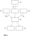
- ein Verfahren zum Betreiben einer elektrischen Maschine des Kraftfahrzeugs.
-
Figur 1 zeigt in einer schematischen Darstellung ein Kraftfahrzeug 1. Das Kraftfahrzeug 1 weist eine Vorderradachse 2 mit zwei Vorderrädern 3 und 4 sowie eine Hinterradachse 5 mit zwei Hinterrädern 6 und 7 auf. - Das Kraftfahrzeug 1 weist außerdem eine Antriebsanordnung 8 mit einer elektrischen Maschine 9 auf, die dazu ausgebildet ist, zumindest eines der Räder 3, 4, 6 und 7 anzutreiben. Beispielsweise ist die Maschine 9 dazu ausgebildet, die Vorderräder 3 und 4, die Hinterräder 6 und 7 oder sowohl die Vorderräder 3 und 4 als auch die Hinterräder 6 und 7 anzutreiben. Optional weist die Antriebsanordnung 8 zusätzlich zu der Maschine 9 zumindest eine weitere elektrische Maschine und/oder zumindest eine Brennkraftmaschine auf.
- Die elektrische Maschine 9 weist einen Rotor 10 auf, der in einem nicht dargestellten Gehäuse der Maschine 9 drehbar gelagert ist. Der Rotor 10 weist eine Permanentmagnetanordnung 12 mit zumindest einem Permanentmagneten 11 auf. Vorliegend sind mehreren Permanentmagneten 11 vorhanden. Die Permanentmagneten 11 sind drehfest mit dem Rotor 10 verbunden und in Umfangsrichtung des Rotors 10 verteilt angeordnet. Beispielsweise handelt es sich bei den Permanentmagneten 11 um Neodym-Eisen-Bor-Magneten 11.
- Die Maschine 9 weist außerdem eine Motorwicklung 13 auf. Vorliegend handelt es sich bei der Motorwicklung 13 um eine Statorwicklung 13 eines Stators 23 der elektrischen Maschine 9. Vorliegend weist die Statorwicklung 13 drei Phasen 14, 15 und 16 auf. Die Phasen 14, 15 und 16 sind derart verteilt um den Rotor 10 angeordnet, dass der Rotor 10 durch eine geeignete Bestromung der Phasen 14, 15 und 16 drehbar ist. Zusätzlich zu der Statorwicklung 13 weist der Stator 23 beispielsweise einen nicht dargestellten Träger für die Statorwicklung 13 auf.
- Die Phasen 14, 15 und 16 sind durch eine mehrere Schaltelemente aufweisende Leistungselektronik 17 der Maschine 9 elektrisch mit einem Energiespeicher 18 des Kraftfahrzeugs 1 verbunden.
- Die elektrische Maschine 9 weist außerdem eine Vorrichtung 19 zum Betreiben der Maschine 9 auf. Die Vorrichtung 19 weist ein Steuergerät 20 auf, das dazu ausgebildet ist, die Schaltelemente der Leistungselektronik 17 anzusteuern beziehungsweise zu schalten.
- Das Kraftfahrzeug 1 weist außerdem einen dem Rotor 10 zugeordneten Drehzahlsensor 21 auf. Der Drehzahlsensor 21 ist dazu ausgebildet, die Ist-Drehzahl NIst des Rotors 10 zu erfassen. Der Drehzahlsensor 21 ist kommunikationstechnisch mit dem Steuergerät 20 verbunden, um dem Steuergerät 20 sein Sensorsignal, also die erfasste Ist-Drehzahl NIst, bereitzustellen.
- Das Kraftfahrzeug 1 weist außerdem einen Temperatursensor 22 auf. Der Temperatursensor 22 ist dem Stator 23 zugeordnet und dazu ausgebildet, die Temperatur des Stators 23 zu erfassen. Der Temperatursensor 22 ist kommunikationstechnisch mit dem Steuergerät 20 verbunden, um dem Steuergerät 20 sein Sensorsignal, also die erfasste Temperatur, bereitzustellen.
- Im Folgenden wird mit Bezug auf
Figur 2 ein vorteilhaftes Verfahren zum Betreiben der elektrischen Maschine 9 mittels des Steuergerätes 20 beschrieben. - In einem ersten Schritt S1 gibt das Steuergerät 20 ein Soll-Drehmoment MSoll vor, das durch die Maschine 9 erzeugt werden soll. Beispielsweise ermittelt das Steuergerät 20 die Höhe des vorgegebenen Soll-Drehmoment MSoll in Abhängigkeit von einer Betätigung eines Beschleunigungspedals durch einen Fahrer des Kraftfahrzeugs 1.
- In einem zweiten Schritt S2 erfasst der Temperatursensor 21 die Temperatur des Stators 23 und stellt die erfasste Temperatur dem Steuergerät 20 bereit.
- In einem dritten Schritt S3 ermittelt das Steuergerät 20 in Abhängigkeit von der durch den Temperatursensor 22 erfassten Temperatur eine Temperaturbelastung der elektrischen Maschine 9. Vorliegend ermittelt das Steuergerät 20 als Temperaturbelastung der elektrischen Maschine 9 die Temperatur des Rotors 10. Dabei ermittelt das Steuergerät 20 die Temperatur des Rotors 10 bevorzugt modellbasiert in Abhängigkeit von der erfassten Temperatur des Stators 23.
- In einem vierten Schritt S4 erfasst der Drehzahlsensor 21 die Ist-Drehzahl NIst des Rotors 10 und stellt dem Steuergerät 20 die erfasste Ist-Drehzahl NIst bereit.
- Die Schritte S1, S2, S3 und S4 werden laufend durchgeführt, sodass laufend das Soll-Drehmoment MSoll, die Temperaturbelastung des Rotors 10 sowie die Ist-Drehzahl NIst des Rotors 10 ermittelt beziehungsweise erfasst werden.
- In einem fünften Schritt S5 entscheidet das Steuergerät 20, ob die elektrische Maschine 9 in einem Standardmodus oder in einem Feldstärkungsmodus beziehungsweise Feldstärkungsbetrieb betrieben werden soll. Hierzu berücksichtigt das Steuergerät 20 in dem Schritt S5 das vorgegebene Soll-Drehmoment MSoll, die ermittelte Temperaturbelastung des Rotors 10 sowie die erfasste Ist-Drehzahl NIst des Rotors 10. Vorzugsweise wird auch der Schritt S5 laufend durchgeführt.
- Dabei gibt das Steuergerät 20 eine Schwellenbelastung für die Temperaturbelastung, eine Schwellendrehzahl für die Ist-Drehzahl NIst sowie ein Schwellendrehmoment für das Soll-Drehmoment MSoll vor. Als Schwellenbelastung gibt das Steuergerät 20 vorliegend eine Schwellentemperatur vor, besonders bevorzugt eine Schwellentemperatur von 230°C. Das Steuergerät 20 vergleicht dann in dem Schritt S5 das Soll-Drehmoment MSoll mit dem vorgegebenen Schwellendrehmoment, die ermittelte Temperaturbelastung mit der vorgegebenen Schwellenbelastung und die erfasste Ist-Drehzahl NIst mit der vorgegebenen Schwellendrehzahl.
- Ergibt der Vergleich, dass die Temperaturbelastung die Schwellenbelastung übersteigt, dass die Ist-Drehzahl NIst die Schwellendrehzahl unterschreitet, und dass das Soll-Drehmoment MSoll das Schwellendrehmoment unterschreitet, so wird auf einen sechsten Schritt S6 verwiesen. In diesem Schritt S6 wird dann die elektrische Maschine 9 in dem Feldstärkungsmodus betrieben. Das Steuergerät 20 steuert dann die Schaltelemente der Leistungselektronik 17 derart an, dass ein durch die Motorwicklung 13 fließender elektrischer Motorstrom einen drehmomentbildenden Stromanteil Iq und einen positiven feldbildenden Stromanteil Id aufweist. Durch den drehmomentbildenden Stromanteil Iq wird erreicht, dass die elektrische Maschine 9 das vorgegebene Soll-Drehmoment MSoll erzeugt. Durch den positiven feldbildenden Stromanteil Id wird erreicht, dass ein Magnetfeld erzeugt wird, das parallel zu dem Magnetfeld der Permanentmagneten 11 ausgerichtet ist. Durch dieses Magnetfeld wird verhindert, dass bei einer die Schwellenbelastung übersteigenden Temperaturbelastung des Rotors 10 die Permanentmagneten 11 entmagnetisiert werden. Insbesondere wird erreicht, dass bereits entmagnetisierte Teile der Permanentmagneten 11 remagnetisiert werden. Insofern wird durch das Betreiben der elektrische Maschine 9 in dem Feldstärkungsmodus die Haltbarkeit der Permanentmagnetanordnung 12 und somit die Haltbarkeit der elektrischen Maschine 9 gesteigert.
- Ergibt der Vergleich in dem Schritt S5 jedoch, dass das Soll-Drehmoment MSoll das Schwellendrehmoment übersteigt, dass die Temperaturbelastung die Schwellenbelastung unterschreitet, und/oder dass die Ist-Drehzahl NIst die Schwellendrehzahl übersteigt, so wird auf einen siebten Schritt S7 verwiesen. In dem siebten Schritt S7 wird dann die elektrische Maschine 9 in dem Standardmodus betrieben. Das Steuergerät 20 steuert dann die Schaltelemente der Leistungselektronik 17 derart an, dass der durch die Motorwicklung 13 fließende elektrische Motorstrom zumindest im Wesentlichen durch den drehmomentbildenden Stromanteil Iq gebildet wird. Der Motorstrom ist also bei Betreiben der Maschine 9 in dem Standardmodus zumindest im Wesentlichen frei von einem positiven oder negativen feldbildenden Stromanteil Id. Dabei wird auch in dem Schritt S7 die Motorwicklung derart bestromt, dass durch den drehmomentbildenden Stromanteil Iq erreicht wird, dass die elektrische Maschine 9 das gewünschte beziehungsweise vorgegebene Soll-Drehmoment MSoll erzeugt.
Claims (9)
- Verfahren zum Betreiben einer elektrischen Maschine, die einen drehbar gelagerten Rotor (10) mit einer Permanentmagnetanordnung und zumindest eine Motorwicklung (13) aufweist, wobei eine Temperaturbelastung der Maschine (9) ermittelt wird, und wobei die Motorwicklung (13) zum Erzeugen eines vorgegebenen Soll-Drehmomentes (MSoll) in Abhängigkeit von der Temperaturbelastung mit einem elektrischen Motorstrom beaufschlagt wird, wobei die Permanentmagnetanordnung Permanentmagnete umfasst,
dadurch gekennzeichnet, dassdie Motorwicklung (13) bei Ermitteln einer einen vorgegebenen Belastungsschwellenwert unterschreitenden Temperaturbelastung derart bestromt wird, dass ein drehmomentbildender Stromanteil (Iq) des Motorstroms zumindest im Wesentlichen dem Motorstrom entspricht
undbei Ermitteln einer den Belastungsschwellenwert übersteigenden Temperaturbelastung ein Feldstärkungsmodus der Maschine (9) eingestellt wird, sodass die elektrische Maschine in dem Feldstärkungsmodus betrieben wird, wobei die Motorwicklung (13) in dem Feldstärkungsmodus derart bestromt wird, dass der Motorstrom einen positiven feldbildenden Stromanteil (Id) aufweist. - Verfahren nach Anspruch 1, dadurch gekennzeichnet, dass die Motorwicklung (13) in dem Feldstärkungsmodus derart bestromt wird, dass der prozentuale Anteil des positiven feldbildenden Stromanteils (Id) an dem Motorstrom zumindest 10% beträgt, vorzugsweise zumindest 20%, besonders bevorzugt zumindest 50%.
- Verfahren nach einem der vorhergehenden Ansprüche, dadurch gekennzeichnet, dass die Motorwicklung (13) in dem Feldstärkungsmodus derart bestromt wird, dass der positive feldbildende Stromanteil (Id) größtmöglich ist.
- Verfahren nach einem der vorhergehenden Ansprüche, dadurch gekennzeichnet, dass als Temperaturbelastung der Maschine (9) die Temperaturbelastung des Rotors (10) ermittelt wird.
- Verfahren nach einem der vorhergehenden Ansprüche, dadurch gekennzeichnet, dass eine Schwellendrehzahl für den Rotor (10) vorgegeben wird, und dass der Feldstärkungsmodus nur bei Vorliegen einer die Schwellendrehzahl unterschreitenden Ist-Drehzahl (NIst) des Rotors (10) eingestellt wird.
- Verfahren nach einem der vorhergehenden Ansprüche, dadurch gekennzeichnet, dass ein Schwellendrehmoment für das Soll-Drehmoment (MSoll) vorgegeben wird, und dass der Feldstärkungsmodus nur bei Vorliegen eines das Schwellendrehmoment unterschreitenden Soll-Drehmomentes (MSoll) eingestellt wird.
- Vorrichtung zum Betreiben einer elektrischen Maschine, wobei die Maschine (9) einen drehbar gelagerten Rotor (10) und zumindest eine Motorwicklung (13) aufweist, dadurch gekennzeichnet, dass die Vorrichtung (19) ein Steuergerät (20) aufweist, das speziell dazu hergerichtet ist, bei bestimmungsgemäßem Gebrauch das Verfahren gemäß einem der vorhergehenden Ansprüche durchzuführen.
- Elektrische Maschine, mit einem drehbar gelagerten Rotor (10), und mit zumindest einer Motorwicklung (13), gekennzeichnet durch eine Vorrichtung (19) gemäß dem vorhergehenden Anspruch.
- Kraftfahrzeug, gekennzeichnet durch eine elektrische Maschine (9) gemäß dem vorhergehenden Anspruch.
Applications Claiming Priority (2)
| Application Number | Priority Date | Filing Date | Title |
|---|---|---|---|
| DE102020215352.3A DE102020215352A1 (de) | 2020-12-04 | 2020-12-04 | Verfahren zum Betreiben einer elektrischen Maschine, Vorrichtung, elektrische Maschine, Kraftfahrzeug |
| PCT/EP2021/080723 WO2022117277A1 (de) | 2020-12-04 | 2021-11-05 | Verfahren zum betreiben einer elektrischen maschine, vorrichtung, elektrische maschine, kraftfahrzeug |
Publications (2)
| Publication Number | Publication Date |
|---|---|
| EP4256696A1 EP4256696A1 (de) | 2023-10-11 |
| EP4256696B1 true EP4256696B1 (de) | 2025-04-23 |
Family
ID=78621853
Family Applications (1)
| Application Number | Title | Priority Date | Filing Date |
|---|---|---|---|
| EP21807030.8A Active EP4256696B1 (de) | 2020-12-04 | 2021-11-05 | Verfahren zum betreiben einer elektrischen maschine, vorrichtung, elektrische maschine, kraftfahrzeug |
Country Status (5)
| Country | Link |
|---|---|
| US (1) | US12413164B2 (de) |
| EP (1) | EP4256696B1 (de) |
| CN (1) | CN116547905A (de) |
| DE (1) | DE102020215352A1 (de) |
| WO (1) | WO2022117277A1 (de) |
Family Cites Families (5)
| Publication number | Priority date | Publication date | Assignee | Title |
|---|---|---|---|---|
| JP2010226914A (ja) * | 2009-03-25 | 2010-10-07 | Toshiba Corp | モータ制御装置,ドラム式洗濯機及び永久磁石モータの着磁制御方法 |
| US20150022126A1 (en) * | 2013-07-18 | 2015-01-22 | GM Global Technology Operations LLC | Method and apparatus for monitoring a permanent magnet electric machine |
| JP6335852B2 (ja) * | 2015-08-05 | 2018-05-30 | 本田技研工業株式会社 | ハイブリッド車両の制御装置 |
| US10106053B2 (en) * | 2016-03-31 | 2018-10-23 | Honda Motor Co., Ltd. | Vehicle |
| DE102017220685A1 (de) | 2017-11-20 | 2019-05-23 | Robert Bosch Gmbh | Verfahren und Vorrichtung zum Betreiben einer elektrischen Maschine zur Abgabe eines vorgegebenen Drehmomentes und einer vorgegebenen Drehzahl |
-
2020
- 2020-12-04 DE DE102020215352.3A patent/DE102020215352A1/de active Pending
-
2021
- 2021-11-05 WO PCT/EP2021/080723 patent/WO2022117277A1/de not_active Ceased
- 2021-11-05 US US18/254,719 patent/US12413164B2/en active Active
- 2021-11-05 EP EP21807030.8A patent/EP4256696B1/de active Active
- 2021-11-05 CN CN202180081526.5A patent/CN116547905A/zh active Pending
Also Published As
| Publication number | Publication date |
|---|---|
| WO2022117277A1 (de) | 2022-06-09 |
| US12413164B2 (en) | 2025-09-09 |
| US20240007034A1 (en) | 2024-01-04 |
| DE102020215352A1 (de) | 2022-06-09 |
| EP4256696A1 (de) | 2023-10-11 |
| CN116547905A (zh) | 2023-08-04 |
Similar Documents
| Publication | Publication Date | Title |
|---|---|---|
| DE102007025210B4 (de) | Motorsteuerung und Motorsteuerungsverfahren | |
| DE102009046583A1 (de) | Verfahren zum Plausibilisieren des Drehmomentes einer elektrischen Maschine und Maschinenregler zur Regelung einer elektrischen Maschine und zur Durchführung des Verfahrens | |
| EP2008358A1 (de) | Ansteuersystem für eine elektrische maschine | |
| EP3815237B1 (de) | Verfahren und vorrichtung zur bestimmung einer lage und drehzahl eines rotors einer elektrischen maschine | |
| DE102009045351A1 (de) | Verfahren zum Betreiben eines Antriebsaggregats sowie Antriebsaggregat | |
| DE102010062338A1 (de) | Verfahren und Vorrichtung zum Betrieb einer fremderregten elektrischen Maschine | |
| DE102014220208A1 (de) | Steuervorrichtung für eine elektromaschine, fahrzeug und verfahren | |
| DE102012201319A1 (de) | Verfahren, Vorrichtung und Computerprogramm zum Ermitteln eines Offsetwinkels in einer Elektromaschine | |
| EP1969714A1 (de) | Verfahren zum bestimmen der magnettemperatur bei synchronmaschinen | |
| DE102011055137A1 (de) | Hybrid-Synchronmaschine | |
| DE102017220685A1 (de) | Verfahren und Vorrichtung zum Betreiben einer elektrischen Maschine zur Abgabe eines vorgegebenen Drehmomentes und einer vorgegebenen Drehzahl | |
| DE102021003612B4 (de) | Verfahren zum Betrieb eines batterieelektrischen Fahrzeugs | |
| WO2022188926A1 (de) | Elektrische maschine, verfahren zur steuerung einer elektrischen maschine, computerprogrammprodukt und steuereinheit | |
| DE102007037884A1 (de) | Motorsteuervorrichtung | |
| EP4256696B1 (de) | Verfahren zum betreiben einer elektrischen maschine, vorrichtung, elektrische maschine, kraftfahrzeug | |
| DE102023004191A1 (de) | Verfahren zum Beheizen eines Kraftfahrzeuges | |
| WO2023147819A1 (de) | Verfahren zum anwerfen eines verbrennungsmotors | |
| WO2019174804A1 (de) | Verfahren zum erkennen eines fehlerzustands einer elektrischen maschine | |
| AT522117B1 (de) | Verfahren zum Betreiben einer Antriebsvorrichtung, Antriebsvorrichtung sowie Kraftfahrzeug | |
| DE102020210097A1 (de) | Verfahren zum Betreiben einer Antriebseinrichtung, Antriebseinrichtung, Kraftfahrzeug | |
| AT522280B1 (de) | Verfahren zum Betreiben einer Antriebsvorrichtung, Computerprogrammprodukt, Antriebsvorrichtung sowie Kraftfahrzeug | |
| EP3014762A2 (de) | Verfahren und vorrichtung zum betreiben einer asynchronmaschine, asynchronmaschine | |
| DE102021204933A1 (de) | Verfahren und Steuergerät zur Steuerung eines aktiven Kurzschlusses bei einer permanentmagneterregten Elektromaschine | |
| DE102022132309A1 (de) | Verfahren zum Betrieb eines Elektromotors | |
| DE102023115444A1 (de) | Verfahren und Vorrichtung zum abgesicherten Betrieb einer elektrischen Maschine |
Legal Events
| Date | Code | Title | Description |
|---|---|---|---|
| STAA | Information on the status of an ep patent application or granted ep patent |
Free format text: STATUS: UNKNOWN |
|
| STAA | Information on the status of an ep patent application or granted ep patent |
Free format text: STATUS: THE INTERNATIONAL PUBLICATION HAS BEEN MADE |
|
| PUAI | Public reference made under article 153(3) epc to a published international application that has entered the european phase |
Free format text: ORIGINAL CODE: 0009012 |
|
| STAA | Information on the status of an ep patent application or granted ep patent |
Free format text: STATUS: REQUEST FOR EXAMINATION WAS MADE |
|
| 17P | Request for examination filed |
Effective date: 20230704 |
|
| AK | Designated contracting states |
Kind code of ref document: A1 Designated state(s): AL AT BE BG CH CY CZ DE DK EE ES FI FR GB GR HR HU IE IS IT LI LT LU LV MC MK MT NL NO PL PT RO RS SE SI SK SM TR |
|
| DAV | Request for validation of the european patent (deleted) | ||
| DAX | Request for extension of the european patent (deleted) | ||
| GRAP | Despatch of communication of intention to grant a patent |
Free format text: ORIGINAL CODE: EPIDOSNIGR1 |
|
| STAA | Information on the status of an ep patent application or granted ep patent |
Free format text: STATUS: GRANT OF PATENT IS INTENDED |
|
| RIC1 | Information provided on ipc code assigned before grant |
Ipc: B60L 15/20 20060101ALN20241211BHEP Ipc: H02P 29/032 20160101ALI20241211BHEP Ipc: H02P 21/00 20160101ALI20241211BHEP Ipc: H02P 29/66 20160101AFI20241211BHEP |
|
| INTG | Intention to grant announced |
Effective date: 20250103 |
|
| GRAS | Grant fee paid |
Free format text: ORIGINAL CODE: EPIDOSNIGR3 |
|
| GRAA | (expected) grant |
Free format text: ORIGINAL CODE: 0009210 |
|
| STAA | Information on the status of an ep patent application or granted ep patent |
Free format text: STATUS: THE PATENT HAS BEEN GRANTED |
|
| AK | Designated contracting states |
Kind code of ref document: B1 Designated state(s): AL AT BE BG CH CY CZ DE DK EE ES FI FR GB GR HR HU IE IS IT LI LT LU LV MC MK MT NL NO PL PT RO RS SE SI SK SM TR |
|
| REG | Reference to a national code |
Ref country code: GB Ref legal event code: FG4D Free format text: NOT ENGLISH |
|
| REG | Reference to a national code |
Ref country code: CH Ref legal event code: EP |
|
| REG | Reference to a national code |
Ref country code: DE Ref legal event code: R096 Ref document number: 502021007308 Country of ref document: DE |
|
| REG | Reference to a national code |
Ref country code: IE Ref legal event code: FG4D Free format text: LANGUAGE OF EP DOCUMENT: GERMAN |
|
| REG | Reference to a national code |
Ref country code: NL Ref legal event code: MP Effective date: 20250423 |
|
| PG25 | Lapsed in a contracting state [announced via postgrant information from national office to epo] |
Ref country code: NL Free format text: LAPSE BECAUSE OF FAILURE TO SUBMIT A TRANSLATION OF THE DESCRIPTION OR TO PAY THE FEE WITHIN THE PRESCRIBED TIME-LIMIT Effective date: 20250423 |
|
| PG25 | Lapsed in a contracting state [announced via postgrant information from national office to epo] |
Ref country code: ES Free format text: LAPSE BECAUSE OF FAILURE TO SUBMIT A TRANSLATION OF THE DESCRIPTION OR TO PAY THE FEE WITHIN THE PRESCRIBED TIME-LIMIT Effective date: 20250423 Ref country code: FI Free format text: LAPSE BECAUSE OF FAILURE TO SUBMIT A TRANSLATION OF THE DESCRIPTION OR TO PAY THE FEE WITHIN THE PRESCRIBED TIME-LIMIT Effective date: 20250423 Ref country code: PT Free format text: LAPSE BECAUSE OF FAILURE TO SUBMIT A TRANSLATION OF THE DESCRIPTION OR TO PAY THE FEE WITHIN THE PRESCRIBED TIME-LIMIT Effective date: 20250825 |
|
| REG | Reference to a national code |
Ref country code: LT Ref legal event code: MG9D |
|
| PG25 | Lapsed in a contracting state [announced via postgrant information from national office to epo] |
Ref country code: NO Free format text: LAPSE BECAUSE OF FAILURE TO SUBMIT A TRANSLATION OF THE DESCRIPTION OR TO PAY THE FEE WITHIN THE PRESCRIBED TIME-LIMIT Effective date: 20250723 Ref country code: GR Free format text: LAPSE BECAUSE OF FAILURE TO SUBMIT A TRANSLATION OF THE DESCRIPTION OR TO PAY THE FEE WITHIN THE PRESCRIBED TIME-LIMIT Effective date: 20250724 |
|
| PG25 | Lapsed in a contracting state [announced via postgrant information from national office to epo] |
Ref country code: PL Free format text: LAPSE BECAUSE OF FAILURE TO SUBMIT A TRANSLATION OF THE DESCRIPTION OR TO PAY THE FEE WITHIN THE PRESCRIBED TIME-LIMIT Effective date: 20250423 |
|
| PG25 | Lapsed in a contracting state [announced via postgrant information from national office to epo] |
Ref country code: BG Free format text: LAPSE BECAUSE OF FAILURE TO SUBMIT A TRANSLATION OF THE DESCRIPTION OR TO PAY THE FEE WITHIN THE PRESCRIBED TIME-LIMIT Effective date: 20250423 |
|
| PG25 | Lapsed in a contracting state [announced via postgrant information from national office to epo] |
Ref country code: HR Free format text: LAPSE BECAUSE OF FAILURE TO SUBMIT A TRANSLATION OF THE DESCRIPTION OR TO PAY THE FEE WITHIN THE PRESCRIBED TIME-LIMIT Effective date: 20250423 |
|
| PG25 | Lapsed in a contracting state [announced via postgrant information from national office to epo] |
Ref country code: RS Free format text: LAPSE BECAUSE OF FAILURE TO SUBMIT A TRANSLATION OF THE DESCRIPTION OR TO PAY THE FEE WITHIN THE PRESCRIBED TIME-LIMIT Effective date: 20250723 |
|
| PG25 | Lapsed in a contracting state [announced via postgrant information from national office to epo] |
Ref country code: IS Free format text: LAPSE BECAUSE OF FAILURE TO SUBMIT A TRANSLATION OF THE DESCRIPTION OR TO PAY THE FEE WITHIN THE PRESCRIBED TIME-LIMIT Effective date: 20250823 |
|
| PG25 | Lapsed in a contracting state [announced via postgrant information from national office to epo] |
Ref country code: LV Free format text: LAPSE BECAUSE OF FAILURE TO SUBMIT A TRANSLATION OF THE DESCRIPTION OR TO PAY THE FEE WITHIN THE PRESCRIBED TIME-LIMIT Effective date: 20250423 |
|
| PG25 | Lapsed in a contracting state [announced via postgrant information from national office to epo] |
Ref country code: SM Free format text: LAPSE BECAUSE OF FAILURE TO SUBMIT A TRANSLATION OF THE DESCRIPTION OR TO PAY THE FEE WITHIN THE PRESCRIBED TIME-LIMIT Effective date: 20250423 Ref country code: DK Free format text: LAPSE BECAUSE OF FAILURE TO SUBMIT A TRANSLATION OF THE DESCRIPTION OR TO PAY THE FEE WITHIN THE PRESCRIBED TIME-LIMIT Effective date: 20250423 |
|
| PGFP | Annual fee paid to national office [announced via postgrant information from national office to epo] |
Ref country code: AT Payment date: 20260113 Year of fee payment: 5 |
|
| PGFP | Annual fee paid to national office [announced via postgrant information from national office to epo] |
Ref country code: FR Payment date: 20251125 Year of fee payment: 5 |
|
| PG25 | Lapsed in a contracting state [announced via postgrant information from national office to epo] |
Ref country code: CZ Free format text: LAPSE BECAUSE OF FAILURE TO SUBMIT A TRANSLATION OF THE DESCRIPTION OR TO PAY THE FEE WITHIN THE PRESCRIBED TIME-LIMIT Effective date: 20250423 |
|
| PG25 | Lapsed in a contracting state [announced via postgrant information from national office to epo] |
Ref country code: EE Free format text: LAPSE BECAUSE OF FAILURE TO SUBMIT A TRANSLATION OF THE DESCRIPTION OR TO PAY THE FEE WITHIN THE PRESCRIBED TIME-LIMIT Effective date: 20250423 |
|
| REG | Reference to a national code |
Ref country code: DE Ref legal event code: R097 Ref document number: 502021007308 Country of ref document: DE |
|
| PG25 | Lapsed in a contracting state [announced via postgrant information from national office to epo] |
Ref country code: SK Free format text: LAPSE BECAUSE OF FAILURE TO SUBMIT A TRANSLATION OF THE DESCRIPTION OR TO PAY THE FEE WITHIN THE PRESCRIBED TIME-LIMIT Effective date: 20250423 |
|
| PG25 | Lapsed in a contracting state [announced via postgrant information from national office to epo] |
Ref country code: IT Free format text: LAPSE BECAUSE OF FAILURE TO SUBMIT A TRANSLATION OF THE DESCRIPTION OR TO PAY THE FEE WITHIN THE PRESCRIBED TIME-LIMIT Effective date: 20250423 |
|
| PLBE | No opposition filed within time limit |
Free format text: ORIGINAL CODE: 0009261 |
|
| STAA | Information on the status of an ep patent application or granted ep patent |
Free format text: STATUS: NO OPPOSITION FILED WITHIN TIME LIMIT |
|
| REG | Reference to a national code |
Ref country code: CH Ref legal event code: L10 Free format text: ST27 STATUS EVENT CODE: U-0-0-L10-L00 (AS PROVIDED BY THE NATIONAL OFFICE) Effective date: 20260304 |
|
| PG25 | Lapsed in a contracting state [announced via postgrant information from national office to epo] |
Ref country code: RO Free format text: LAPSE BECAUSE OF FAILURE TO SUBMIT A TRANSLATION OF THE DESCRIPTION OR TO PAY THE FEE WITHIN THE PRESCRIBED TIME-LIMIT Effective date: 20250423 |
|
| 26N | No opposition filed |
Effective date: 20260126 |
|
| PGFP | Annual fee paid to national office [announced via postgrant information from national office to epo] |
Ref country code: DE Payment date: 20260126 Year of fee payment: 5 |