EP4256397B1 - Vorrichtungen, systeme und verfahren zur erfassung von szenenbildern - Google Patents
Vorrichtungen, systeme und verfahren zur erfassung von szenenbildern Download PDFInfo
- Publication number
- EP4256397B1 EP4256397B1 EP21900195.5A EP21900195A EP4256397B1 EP 4256397 B1 EP4256397 B1 EP 4256397B1 EP 21900195 A EP21900195 A EP 21900195A EP 4256397 B1 EP4256397 B1 EP 4256397B1
- Authority
- EP
- European Patent Office
- Prior art keywords
- sroi
- imaging
- specular
- scene
- orientation
- Prior art date
- Legal status (The legal status is an assumption and is not a legal conclusion. Google has not performed a legal analysis and makes no representation as to the accuracy of the status listed.)
- Active
Links
Images


Classifications
-
- G—PHYSICS
- G06—COMPUTING OR CALCULATING; COUNTING
- G06V—IMAGE OR VIDEO RECOGNITION OR UNDERSTANDING
- G06V10/00—Arrangements for image or video recognition or understanding
- G06V10/40—Extraction of image or video features
- G06V10/60—Extraction of image or video features relating to illumination properties, e.g. using a reflectance or lighting model
-
- G—PHYSICS
- G02—OPTICS
- G02B—OPTICAL ELEMENTS, SYSTEMS OR APPARATUS
- G02B27/00—Optical systems or apparatus not provided for by any of the groups G02B1/00 - G02B26/00, G02B30/00
- G02B27/28—Optical systems or apparatus not provided for by any of the groups G02B1/00 - G02B26/00, G02B30/00 for polarising
- G02B27/281—Optical systems or apparatus not provided for by any of the groups G02B1/00 - G02B26/00, G02B30/00 for polarising used for attenuating light intensity, e.g. comprising rotatable polarising elements
-
- G—PHYSICS
- G02—OPTICS
- G02B—OPTICAL ELEMENTS, SYSTEMS OR APPARATUS
- G02B26/00—Optical devices or arrangements for the control of light using movable or deformable optical elements
- G02B26/02—Optical devices or arrangements for the control of light using movable or deformable optical elements for controlling the intensity of light
- G02B26/023—Optical devices or arrangements for the control of light using movable or deformable optical elements for controlling the intensity of light comprising movable attenuating elements, e.g. neutral density filters
-
- G—PHYSICS
- G02—OPTICS
- G02B—OPTICAL ELEMENTS, SYSTEMS OR APPARATUS
- G02B27/00—Optical systems or apparatus not provided for by any of the groups G02B1/00 - G02B26/00, G02B30/00
- G02B27/0018—Optical systems or apparatus not provided for by any of the groups G02B1/00 - G02B26/00, G02B30/00 with means for preventing ghost images
-
- G—PHYSICS
- G02—OPTICS
- G02B—OPTICAL ELEMENTS, SYSTEMS OR APPARATUS
- G02B27/00—Optical systems or apparatus not provided for by any of the groups G02B1/00 - G02B26/00, G02B30/00
- G02B27/28—Optical systems or apparatus not provided for by any of the groups G02B1/00 - G02B26/00, G02B30/00 for polarising
- G02B27/288—Filters employing polarising elements, e.g. Lyot or Solc filters
-
- G—PHYSICS
- G02—OPTICS
- G02B—OPTICAL ELEMENTS, SYSTEMS OR APPARATUS
- G02B5/00—Optical elements other than lenses
- G02B5/20—Filters
-
- G—PHYSICS
- G02—OPTICS
- G02B—OPTICAL ELEMENTS, SYSTEMS OR APPARATUS
- G02B5/00—Optical elements other than lenses
- G02B5/30—Polarising elements
-
- G—PHYSICS
- G03—PHOTOGRAPHY; CINEMATOGRAPHY; ANALOGOUS TECHNIQUES USING WAVES OTHER THAN OPTICAL WAVES; ELECTROGRAPHY; HOLOGRAPHY
- G03B—APPARATUS OR ARRANGEMENTS FOR TAKING PHOTOGRAPHS OR FOR PROJECTING OR VIEWING THEM; APPARATUS OR ARRANGEMENTS EMPLOYING ANALOGOUS TECHNIQUES USING WAVES OTHER THAN OPTICAL WAVES; ACCESSORIES THEREFOR
- G03B15/00—Special procedures for taking photographs; Apparatus therefor
-
- G—PHYSICS
- G03—PHOTOGRAPHY; CINEMATOGRAPHY; ANALOGOUS TECHNIQUES USING WAVES OTHER THAN OPTICAL WAVES; ELECTROGRAPHY; HOLOGRAPHY
- G03B—APPARATUS OR ARRANGEMENTS FOR TAKING PHOTOGRAPHS OR FOR PROJECTING OR VIEWING THEM; APPARATUS OR ARRANGEMENTS EMPLOYING ANALOGOUS TECHNIQUES USING WAVES OTHER THAN OPTICAL WAVES; ACCESSORIES THEREFOR
- G03B7/00—Control of exposure by setting shutters, diaphragms or filters, separately or conjointly
- G03B7/18—Control of exposure by setting shutters, diaphragms or filters, separately or conjointly in accordance with light-reducing "factor" of filter or other obturator used with or on the lens of the camera
-
- G—PHYSICS
- G06—COMPUTING OR CALCULATING; COUNTING
- G06V—IMAGE OR VIDEO RECOGNITION OR UNDERSTANDING
- G06V10/00—Arrangements for image or video recognition or understanding
- G06V10/20—Image preprocessing
- G06V10/25—Determination of region of interest [ROI] or a volume of interest [VOI]
-
- H—ELECTRICITY
- H04—ELECTRIC COMMUNICATION TECHNIQUE
- H04N—PICTORIAL COMMUNICATION, e.g. TELEVISION
- H04N23/00—Cameras or camera modules comprising electronic image sensors; Control thereof
- H04N23/70—Circuitry for compensating brightness variation in the scene
- H04N23/73—Circuitry for compensating brightness variation in the scene by influencing the exposure time
-
- G—PHYSICS
- G03—PHOTOGRAPHY; CINEMATOGRAPHY; ANALOGOUS TECHNIQUES USING WAVES OTHER THAN OPTICAL WAVES; ELECTROGRAPHY; HOLOGRAPHY
- G03B—APPARATUS OR ARRANGEMENTS FOR TAKING PHOTOGRAPHS OR FOR PROJECTING OR VIEWING THEM; APPARATUS OR ARRANGEMENTS EMPLOYING ANALOGOUS TECHNIQUES USING WAVES OTHER THAN OPTICAL WAVES; ACCESSORIES THEREFOR
- G03B2206/00—Systems for exchange of information between different pieces of apparatus, e.g. for exchanging trimming information, for photo finishing
Definitions
- aspects of disclosed embodiments pertain to systems, devices and/or methods configured to acquire images of a scene comprising reflective specular surfaces and which are further configured to reduce or eliminate unwanted reflections (also: glare) from the reflective specular surfaces.
- Some embodiments pertain to the reduction or elimination of unwanted specular reflections for imaging a portion of the scene behind a transparent and specular surface, for example, to allow characterizing the scene portion and/or characterizing one or more objects which may be located behind the transparent and reflective specular surface.
- specular light reflections may originate from natural and/or artificial light sources. Depending on the scene acquisition conditions, the same surface may exhibit or may not exhibit specular characteristics.
- a scene portion that is behind a specular surface that is also transparent may herein be referred to as a scene's specular region-of-interest ("specular ROI” or "sROI").
- specular ROI specular region-of-interest
- the sROI may be defined by the boundaries of the transparent and specular surface (e.g., window frame, windshield frame).
- a transparent and specular surface may cover the entire field-of-view (FOV) of an image acquisition device.
- ex-sROI A scene portion that does not include the area behind a transparent and specular surface may herein be referred to as ex-sROI.
- ex-sROI may or may not comprise specular surfaces.
- ex-sROI may comprise opaque and specular surfaces such as, for example, a car's motor hood.
- any “transparent surface” is herein considered to be “at least partially transparent” and includes, for example, surfaces having 50% or 60%, 70% or substantially perfect transparency.
- transparent may pertain a variety of wavelengths including the visible spectrum and/or the near-infrared and/or infrared wavelength spectrum and/or other portions of the electro-magnetic spectrum.
- a reduction in imaged reflections may pertain mainly to specular reflections, which include linear polarization (e.g., s-polarization).
- specular surfaces can include glass, water and/or metallic surfaces.
- imaging a scene comprising a specular and, optionally, transparent surface which is positioned between an image acquisition device and an object can be performed without requiring polarization analysis of the light reflected from the surface for filtering filter out unwanted reflections by a polarization filter.
- no on-site light polarization measurement may be required for reducing or filtering out specular reflections reflected from a specular surface.
- devices and systems described herein are configured to reduce or prevent the imaging of unwanted reflections without user-noticeable latency or with near-zero latency, e.g., in real-time (RT) or near-RT.
- Embodiments pertain to the gathering or acquiring of data descriptive of a specular sROI located behind transparent and specular surfaces and ex-sROI, for example, for monitoring, controlling, and/or intelligence gathering purposes.
- Acquiring specular sROI and ex-sROI data may be followed by data analysis for characterization of the specular sROI and ex-sROI.
- Monitoring, controlling and/or intelligence gathering may include, for example, characterizing objects which are located in the specular sROI and the ex-sROI. Characterizing an object may include, for example, object identification and/or classification.
- object characterization may be employed for identification and, optionally, authentication purposes, for example, using facial and/or other physical characteristics recognition (e.g., gait analysis) and comparison with corresponding physical characteristics of known individuals.
- aspects of devices, systems and methods described herein may thus be employed in the context of, for example, border control applications, perimeter surveillance, authentication applications for access control, remote in-vehicle or in-platform passenger recognition, counting the number of passengers in vehicles or platforms, measuring physical characteristics of passengers in vehicles (e.g., passenger height) and/or the like.
- an imaging system comprises one or more image acquisition devices or cameras that include imaging optics and an image sensor comprising a plurality of pixels generating signals related to the imaged scene.
- the imaging optic is configured to direct light received from the scene onto the image sensor.
- the image acquisition device further includes an adjustable polarization filter that is positioned between at least one specular surface and the one or more image sensors for acquiring information about a scene.
- the adjustable polarization may be configured to enable acquiring information about the sROI which is behind the specular and transparent surface.
- the specular and transparent surface is thus positioned between the camera and the specular sROI.
- a plurality of image sensors may be employed along with a corresponding plurality of polarization filters.
- the plurality of image sensors and polarizers may be employed by the same image acquisition device or by separate image acquisition devices which are employed by the scene acquisition system.
- the polarization filter orientation may be adjusted and set to a desired orientation based on scene imaging parameters including, for example, an image acquisition direction relative to a platform in a scene to reduce or eliminate reflections from the specular surface.
- the desired polarizer orientation may remain fixed for a certain camera position and orientation.
- additional scene imaging parameters may be considered which may include, for instance, polarization of light incident onto the image sensor; environmental conditions (e.g., weather conditions, time of day, ambient light, and/or sun position) in relation to the geographic area comprising the scene being imaged and/or in which the camera is located.
- the system may also be configured to determine, in addition to a desired polarizer orientation, a desired camera orientation in a scene such to further reduce or prevent specular reflection from reaching an image sensor.
- a lateral displacement of an image acquisition device relative to a specular surface is significantly shorter than a distance between the device and the specular surface, such that a change in acquisition direction due to lateral displacement between the image acquisition device and the specular surface can be considered negligible.
- the lateral shift is considered to determine a corresponding change in the image acquisition direction. For example, a lateral displacement (up/down and/or sideways) between the image acquisition device and the specular surface exceeding (increasing or decreasing) a high viewpoint angle threshold may be taken into consideration by the system for updating an initial polarizer orientation to obtain an updated desired polarizer orientation.
- the upper viewpoint angle threshold may be 5 degrees.
- a characteristic (e.g., orientation) of the polarization filter is configured such that, for example, the sROI behind a specular and transparent surface becomes sufficiently visible to allow sROI characterization.
- specular sROI characterization may include, for example, characterization of objects located behind the specular and transparent surface for instance, for the purposes of object identification, classification and/or authentication.
- the polarizer may be configured to allow object characterization comprised in ex-sROI.
- the system may be operable to automatically switch between different polarizer configurations when imaging the sROI and ex-sROI of the scene in manner to reduce or prevent the effect on imaging of unwanted specular reflections from either one of the sROI and ex-sROI.
- a specular sROI may be considered "sufficiently visible” if objects in the specular sROI are identifiable, for example, by the naked human eye and/or (e.g., automatically or semi-automatically) by an electronic analysis system, and/or the like.
- the electronic analysis system may for instance be operable to characterize image data descriptive of the specular sROI.
- an image comprising the specular sROI behind the specular and transparent surface may be displayed to a user of the system.
- an output relating to characteristics of the specular sROI may be output by the system.
- the output may include, for example, visual information, auditory information and/or tactile information.
- information for characterizing the specular sROI may be provided in a non-visual manner.
- a specular surface (which may comprise opaque surface portions and transparent surface portions) may be part of a stationary and/or movable (e.g., mobile) platform.
- a specular and transparent surface of a platform may include, for example, a vehicle window such as the window of a passenger car; truck; bus; the window of a rail-based transport vehicle including trains, subways, trams, etc.; a cockpit window; an aircraft window; the window of a building such as the window of a residential building, an office building window, a shopping window; a glass door; a sentry box window; and/or the like.
- a specular and opaque surface may include metallic platform surfaces.
- a characteristic (e.g., orientation) of the polarization filter may be configured (e.g., controlled) based on an orientation of the specular surface relative to the image sensor.
- an imaging system may be configured to automatically analyze an orientation of a specular surface relative to the image sensor to determine a desired polarization filter orientation.
- the desired polarization filter orientation the amount of specular reflections incident onto the image sensor(s) may be reduced or prevented.
- the polarization filter may be set to the desired orientation in a manual, automatic or semi-automatic manner.
- controlling a polarization filter orientation may be based mainly or solely on the specular surface orientation relative to the image sensor.
- the orientation of a specular surface in a scene relative to a (e.g., world) reference frame and/or relative to a camera's imaging direction may be predictable and/or constant or substantially constant over a comparatively long period of time. Therefore, slight variations in orientation of a specular surface relative to the world reference frame and/or to the imaging direction may be considered negligible as long as or if these variations allow, for a desired polarization filter orientation, generating images of the scene behind the specular and transparent surface, for example, to enable specular sROI and ex-sROI characterization including, for instance object characterization.
- camera-surface orientation values may be associated with (also: mapped to) corresponding desired polarizer orientation values.
- the camera-surface orientations values may be associated with the corresponding range of desired polarizer orientation values through a look-up-table and/or through a mathematical function.
- polarizer orientations may be predetermined with respect to predicted camera-surface orientation estimations.
- the orientation of a specular surface relative to a (e.g., world) reference frame and/or relative to an image sensor located may be predictable and/or constant or substantially constant over a comparatively long period of time, considering natural and/or manmade physical characteristics of a geographical area in which the specular surface and image sensor are located.
- Manmade physical characteristics may pertain, for example, the position, orientation and/or configuration of buildings (e.g., window position, orientation and/or height above ground), artificial lighting configuration (e.g., streetlights), infrastructure including roadways and venues accessed by the roadways, parking lots, and/or the like.
- buildings e.g., window position, orientation and/or height above ground
- artificial lighting configuration e.g., streetlights
- infrastructure including roadways and venues accessed by the roadways, parking lots, and/or the like.
- Natural physical characteristics may pertain, for example, to terrain topography, vegetation, geological characteristics, and/or the like, in a geographic area.
- the orientation of a specular surface within a scene may depend on such manmade and/or natural characteristics of the scene.
- an expected or instantaneous orientation of a specular surface in a scene may depend on manmade and/or natural characteristics
- an (e.g., expected or instantaneous) orientation of a specular surface relative to a selected imaging direction may depend on manmade and/or natural scene characteristics. Therefore, an (e.g., expected or instantaneous) orientation of a specular surface may be determined (e.g., estimated) based on manmade and/or natural scene characteristics.
- a polarization filter orientation may be configured based on knowledge of manmade and/or natural scene characteristics and further based on a selected imaging direction (pitch, yaw) of the acquisition device within the scene.
- indoor scene imaging applications may include, for example, imaging a scene in a parking garage, underground and/or above ground mass transportation facilities (e.g., subway stations, train stations, airport terminals, and/or the like.
- a platform or specular surface in a scene may be considered to have a basic orientation with respect to yaw and/or pitch relative to the scene's reference coordinates.
- the basic orientation may pertain to a nominal orientation as well as to deviations from the nominal orientation within a maximum deviation range.
- An initial desired polarizer configuration may be configured with respect to such nominal platform orientation.
- the deviation may be considered negligible and therefore not used as an input parameter for updating the desired polarizer orientation.
- the initial desired polarizer orientation is updated to obtain a new (also: updated) polarizer orientation.
- the system may be configured to determine a platform's orientation and update the polarizer configuration when the deviation exceeds the maximum deviation range.
- the system may be configured to perform these steps in real-time or substantially in real-time.
- a maximum deviation range may be defined by +/-5 degrees from the nominal platform orientation.
- the position and orientation of a closed office building window with respect to a world reference frame may remain constant.
- the orientation of platforms expected to traverse along a certain route may be predictable for any platform position along that route.
- one of two possible orientations of a vehicle to be parked in that parking space is predictable.
- Orientations of vehicles traveling along a road or parking in a basic orientation may slightly vary among different vehicles. However, as mentioned above such variations may in some embodiments be considered negligible with respect to an image sensor positioned relative to the vehicle(s) for capturing or acquiring sufficient quality images of persons located in the vehicle(s) for identification purposes. Therefore, a polarization filter may be set to an angular orientation allowing filtering out specular reflections for the purpose of identifying persons located in a vehicle, without requiring readjustment of the polarization filter due to the above noted slight variations.
- the relative specular surface and image sensor orientations may be predictable, yet change significantly within a comparatively short period of time.
- polarization filter orientations can be controlled comparatively fast.
- a polarization filter orientation can be adjusted (e.g., solely) based on a known route expected to be or being traversed by a vehicle and further based on the sensor's vehicle acquisition angle for each instant vehicle position along the said route.
- the orientation of the platform's transparent and specular surface relative to an image sensor's FOV capturing the platform may be predictable or derivable.
- a sensor's scene imaging direction may be constant.
- a selected polarization filter orientation may remain constant in accordance with a present or expected specular surface orientation in the sensor's FOV.
- a polarization filter orientation may be configured for a selected specular surface orientation relative to an image sensor.
- the polarization filter configuration may be retained for any specular surface subsequently entering the image sensor's frame while effectively reducing or preventing the effect of specular reflections.
- the imaging system may be configured to acquire images of a plurality of vehicles entering one after the other the image sensor's FOV.
- the position and imaging direction of the image sensor may be stationary in the geographic area and the polarization filter configuration may be set to a correspondingly constant value to perform image acquisition of vehicles driving on a road to obtain images of sufficient quality of persons located in the vehicles "passing by" the sensor's FOV.
- an imaging system may be configured to detect a (moving) platform, lock onto the platform and track it is an object of interest (OOI).
- Platform tracking may be implemented by a plurality of cameras that are positioned in different imaging directions and/or by at least one camera that is coupled with an (e.g., gymbaled) steering mechanism for controllably steering the camera, for example, in three degrees of freedom.
- the polarization filter configurations may be preset or predetermined for the various imaging directions of the at least one steerable camera and/or the plurality of cameras.
- the imaging system may be configured to determine platform (e.g., vehicle) characteristics. These platform characteristics may be considered for determining the orientation of a vehicle's specular surfaces, e.g., relative to the reference frame and/or the camera's imaging optics, for example, by comparing acquired platform characteristics with known platform characteristics, for instance, by using one or more known platform databases.
- platform e.g., vehicle
- platform characteristics may be considered for determining the orientation of a vehicle's specular surfaces, e.g., relative to the reference frame and/or the camera's imaging optics, for example, by comparing acquired platform characteristics with known platform characteristics, for instance, by using one or more known platform databases.
- polarizer configurations may set based on where an image of a platform is shown on the screen of a display device. For example, a first polarization filter configuration may be selected when a platform's image is displayed on an upper left screen region, and a second polarization filter configuration, different from the first one, may be selected when a platform's image is displayed on an upper left screen region. Accordingly, in some embodiments, different screen display regions may be associated with different polarizer configurations. The different screen display regions may be partially overlapping.
- reflected light characteristics such as polarization may be disregarded when configuration the polarization filter.
- environmental conditions such as time of day or weather conditions may be disregarded for determining the polarization filter orientation.
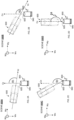
- FIGS. 1A-C and FIGs. 2A-D various scene images 500A-D are shown in which images of a vehicle 600 having a vehicle longitudinal axis Vz is acquired from different imaging directions by a camera 800 having a camera optical axis Cz and comprising acquisition optics 820 and an image sensor 840 aligned with optical axis Cz.
- vehicle 600 comprises transparent and specular surfaces 610 (e.g., vehicle windshield) which introduce specular reflections into the camera's FOV.
- specular reflections increasingly obscure or hide visibility of the scene portion behind specular and transparent surface 610 and, therefore, of an object 700 (exemplified herein as a driver of the vehicle) positioned behind specular and transparent surface 610.
- object 700 e.g., a driver of the vehicle
- specular reflections are introduced which render object 700 nearly to entirely invisible.
- the orientation of imaging optics of a camera relative to a specular surface may be determined. Based on the determined surface-imaging optics orientation, the angle or orientation of a polarization filter may be configured to reduce or eliminate the imaging of unwanted specular reflections by an image sensor.
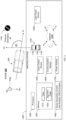
- an imaging system 1000 is described which is configured to reduce or eliminate the effect of unwanted specular reflections.
- Imaging system 1000 comprises a camera 1100 that includes imaging optics 1120 configured to receive and optically guide light received from scene 500 onto an image sensor 1140 of camera 1100 to generate image data descriptive of the scene.
- Camera 1100 further includes a polarizer or polarization filter 1160 which can be set into a desired orientation such to reduce or eliminate specular reflections received from scene 500.
- At least one camera 1100 may include one or more cameras for imaging in the visible or infrared spectrum, an array of video cameras, e.g., arranged for acquiring 360 degrees video images from the scene or multiple video cameras scattered in scene 500.
- the one or more video cameras may be configurable such that parameters thereof such as zooming, illumination, orientation, positioning, location and/or the like, can be adapted (e.g., adjusted, configured, and/or directed from afar), automatically, manually and/or semi-automatically.
- camera 1100 may comprise a plurality of imaging modules such as, for instance, a Tele-lens assembly and a wide FOV lens assembly having corresponding optical imaging axes.
- the plurality of imaging modules may be incorporated in a Smartphone device.
- a polarizer 1160 may be pre-installed in camera 1100.
- camera 1100 may be retrofitted with polarizer 1160.
- polarizer 1160 may be positioned in front of imaging optics 1120. In some other embodiments, polarizer 1160 may be positioned between image sensor 1140 and imaging optics 1120.
- Imaging system 1000 may further include a processor 1200 and a memory 1300 which is configured to store data 1310 and algorithm code 1320.
- Processor 1200 may be configured to execute algorithm code 1320 for the processing of data 1310 resulting in the implementation of a scene acquisition control and analysis (SACA) engine 1400.
- SACA scene acquisition control and analysis
- SACA engine 1400 may be configured to determine a present or expected orientation (also: camera-surface orientation) between a specular surface and camera 1100. SACA engine 1400 is further configured to determine, based on the determined camera-surface orientation, a desired polarizer orientation that reduces or eliminates incidence of unwanted specular onto the image sensor.
- the surface-camera orientation may for example be determined as outlined in more detail herein below.
- Processor 1200 may be implemented by various types of processor devices and/or processor architectures including, for example, embedded processors, communication processors, graphics processing unit (GPU)-accelerated computing, soft-core processors and/or general purpose processors.
- processors may additionally or alternatively refer to a controller.
- Processor 1200 may be implemented by various types of processor devices and/or processor architectures including, for example, embedded processors, communication processors, graphics processing unit (GPU)-accelerated computing, soft-core processors and/or general purpose processors.
- GPU graphics processing unit
- Memory 1300 may be implemented by various types of memories, including transactional memory and/or long-term storage memory facilities and may function as file storage, document storage, program storage, or as a working memory. The latter may for example be in the form of a static random access memory (SRAM), dynamic random access memory (DRAM), read-only memory (ROM), cache and/or flash memory.
- SRAM static random access memory
- DRAM dynamic random access memory
- ROM read-only memory
- cache flash memory
- memory 1300 may, for example, include, e.g., temporally-based and/or non-temporally based instructions.
- long-term memory memory 1300 may for example include a volatile or non-volatile computer storage medium, a hard disk drive, a solid state drive, a magnetic storage medium, a flash memory and/or other storage facility.
- a hardware memory facility may for example store a fixed information set (e.g., software code) including, but not limited to, a file, program, application, source code, object code, data, and
- Imaging system 1000 may further include an input/output device 1500 which may be configured to provide or receive any type of data or information.
- input/output device 1500 may include, for example, visual presentation devices or systems such as, for example, computer screen(s), head mounted display (HMD) device(s), first person view (FPV) display device(s), device interfaces (e.g., a Universal Serial Bus interface), and/or audio output device(s) such as, for example, speaker(s) and/or earphones.
- Input/output device 1500 may be employed to access information generated by the system and/or to provide inputs including, for instance, control commands, operating parameters, queries and/or the like.
- input/output device 1500 may allow a user of imaging system 1000 to perform one or more of the following: approval of system-suggested object identification and/or of their attributes; camera control; providing a command input to lock onto and track a movable platform.
- imaging system 1000 may be configured to automatically or semi-automatically perform object identification and tracking of the object as a target.
- Imaging system 1000 may further comprise at least one communication module 1600 configured to enable wired and/or wireless communication between the various components and/or modules of the system and which may communicate with each other over one or more communication buses (not shown), signal lines (not shown) and/or a network infrastructure.
- at least one communication module 1600 configured to enable wired and/or wireless communication between the various components and/or modules of the system and which may communicate with each other over one or more communication buses (not shown), signal lines (not shown) and/or a network infrastructure.
- Network 1800 may be configured for using one or more communication formats, protocols and/or technologies such as, for example, to internet communication, optical or RF communication, telephony-based communication technologies and/or the like.
- communication module 1600 may include I/O device drivers (not shown) and network interface drivers (not shown) for enabling the transmission and/or reception of data over network 1800.
- a device driver may for example, interface with a keypad or to a USB port.
- a network interface driver may for example execute protocols for the Internet, or an Intranet, Wide Area Network (WAN), Local Area Network (LAN) employing, e.g., Wireless Local Area Network (WLAN)), Metropolitan Area Network (MAN), Personal Area Network (PAN), extranet, 2G, 3G, 3.5G, 4G, 5G, 6G mobile networks, 3GPP, LTE, LTE advanced, Bluetooth ® (e.g., Bluetooth smart), ZigBee TM , near-field communication (NFC) and/or any other current or future communication network, standard, and/or system.
- WAN Wide Area Network
- LAN Local Area Network
- WLAN Wireless Local Area Network
- MAN Metropolitan Area Network
- PAN Personal Area Network
- extranet 2G, 3G, 3.5G, 4G, 5G, 6G mobile networks
- 3GPP LTE, LTE advanced, Bluetooth ® (e.g., Bluetooth smart), ZigBee TM , near-field communication (NFC) and/or any other current or future communication network, standard
- Imaging system 1000 may further include a power module 1700 for powering the various components and/or modules and/or subsystems of the system.
- Power module 1700 may comprise an internal power supply (e.g., a rechargeable battery) and/ or an interface for allowing connection to an external power supply.
- processors and/or memories may be allocated to each component and/or module of imaging system 1000.
- description and claims may refer to a single module and/or component.
- processor 1200 may be implemented by several processors, the following description will refer to processor 1200 as the component that conducts all the necessary processing functions of imaging system 1000.
- imaging system 1000 may be implemented fully or partially by a multifunction mobile communication device also known as "smartphone", a mobile or portable device, a non-mobile or non-portable device, a digital video camera, a personal computer, a laptop computer, a tablet computer, a server (which may relate to one or more servers or storage systems and/or services associated with a business or corporate entity, including for example, a file hosting service, cloud storage service, online file storage provider, peer-to-peer file storage or hosting service and/or a cyberlocker), personal digital assistant, a workstation, a wearable device, a handheld computer, a notebook computer, a vehicular device, a non-vehicular device, a stationary device and/or a home appliances control system.
- camera 1100 may be a smartphone camera, and some of SACA engine 1400 functionalities may be implemented by the smartphone and some by devices and/or system external to the smartphone. Alternative configurations may also be conceived.
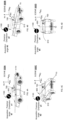
- SACA engine 1400 may be configured to determine a present or expected camera-surface orientation of the camera's optical axis Cz relative to transparent and specular surface 610.
- SACA engine 1400 may analyze scene image data descriptive of captured scene 500 comprising platform 600 and determine, based on the performed analysis, a present or expected camera-platform orientation.
- the expression "camera-platform orientation” may herein be referred to as the angle ⁇ formed between a platform (e.g., vehicle) longitudinal axis Vz relative to the camera optical axis Cz. It is noted that alternative definitions may be used for describing relative orientations between the camera and the platform.
- the corresponding present or expected relative camera-surface orientation between a vehicle's specular surface 610 and the camera optical axis Cz may be derived to determine, based on the derived camera-surface orientation, a desired polarizer orientation to reduce or prevent specular reflections from entering the camera's FOV.
- the camera-surface orientation may be determined without prior determination of the present or expected camera-vehicle orientation to determine, based on the camera-surface orientation, a desired polarizer orientation.
- methods that are based on artificial intelligence may be employed to determine a present or expected camera-surface orientation.
- a desired polarizer orientation ⁇ can be determined without requiring but not necessarily excluding the measurement or calculation of light polarization.
- a desired polarizer orientation ⁇ can be determined without requiring but without necessarily excluding environmental conditions (e.g., weather conditions and/or considering of sun position).
- a range of camera-surface orientation values may be associated with a corresponding desired range of polarizer orientation values, for example, through a look-up-table and/or through a mathematical function.
- polarizer orientations may be predetermined with respect to corresponding camera-surface orientations.
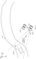
- the orientation ⁇ of platform 600 changes relative to world reference coordinate system Wxzy while the camera's orientation relative to Wxyz remains stationary.
- the camera-surface orientation may be determined, for example, by considering platform characteristics. With respect to a vehicle, such characteristics may include, for example, the type of vehicle (e.g., passenger car, truck, bus); vehicle category (e.g., sportscar, SUV, family car), vehicle make (e.g., Mazda, Volkswagen, Porsche) and/or year of manufacturing.
- SACA engine 1400 may for example compare data relating to imaged vehicle 600 with vehicle information stored in a vehicle database of the system's memory 1300.
- the respective vehicle information may be used as a basis for determining the camera-surface orientation to determine a desired polarizer orientation ⁇ .
- polarizer orientations ⁇ 1- ⁇ 4 are associated with camera-platform orientations ⁇ 1- ⁇ 4 resulting in that object 700 remains characterizable (e.g., identifiable, authenticable, classifiable) through transparent and specular surface 610 for any of the example camera-platform orientations ⁇ 1- ⁇ 4.
- a present or expected camera-surface orientation may be determined based on natural and/or manmade characteristics of a geographical area.
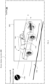
- the orientation of a vehicle in a certain geographical area can be assumed to be substantially constant relative to world reference coordinate system, considering for instance manmade physical characteristics such as roadway 510.
- vehicle 600 may be considered to have a basic orientation, as defined herein above. For example, if roadway 510 is a one-way street or a highway lane, vehicles driving on roadway 510 can be considered to travel in a predefined direction D relative to world reference coordinate system Wxyz.
- the orientation of a vehicle's specular surface relative to the camera's imaging direction can be determined.
- the camera-vehicle orientation may be considered identical to the orientation of road direction relative to camera 1100.
- the determined camera-road orientation may then be used to derive (e.g., estimate) a camera-surface orientation.
- Polarizer orientations ⁇ 1- ⁇ 4 which are associated with the camera-platform orientations ⁇ 1- ⁇ 4 are schematically illustrated in FIGs. 6A-D and 7A-D .
- imaging system 1000 may receive data relating to camera 1100 including, for example, camera position (e.g., time-position tuple) with respect to world reference coordinate system Wxzy, a present camera pitch and/or yaw value, camera zoom range, a present camera zoom value, dynamic range, contrast, image autocorrection parameters, and/or the like.
- camera data may be provided by inertial sensors and/or non-inertial sensors.
- Non-inertial sensors may include, for example, one or more barometers, proximity sensors, altimeters, magnetometers, a compass, light sensors (e.g., for measuring the amount of incident sunlight), tactile sensors (e.g., touch screen sensors), receivers of a space-based satellite navigation system, and/or a front and/or back camera.
- Inertial sensors may include, for example, a gyroscope and/or an accelerometer.
- camera position and orientation may be provided by a receiver of a space-based satellite navigation system (e.g., GPS, GLONASS), by apparatuses for implementing a navigation system that is not based on a satellite system, and/or an inertial senor.
- imaging system 1000 may receive data descriptive of information relating to geographical characteristics of a scene to be captured by camera 1100.
- Information about geographical characteristics of a scene to be captured by camera 1100 may be obtained from map data (e.g., 2D or 3D map of scene 500), and/or atlases.
- map data may be received by imaging system 1000 from one or more sensors (e.g., camera 1100) in real time or near real-time (RT) and/or from a database storing publicly available scene information comprising satellite images and/or maps, for example, from publicly available sources (e.g., satellite images and/or maps) fetched from respective map services (e.g., Google ® Maps, Google ® Earth, Bing ® Maps, Leaflet ® , MapQuest ® and/or the like).
- sensors e.g., camera 1100
- RT near real-time
- map services e.g., Google ® Maps, Google ® Earth, Bing ® Maps, Leaflet ® , MapQuest ® and/or the like.
- imaging system 1000 may be configured to automatically analyze (real-time (RT) or non-RT) image data descriptive of a geographical area to identify various geographical features and characterize the geographical features. For instance, a data may be automatically characterized as road information along with a corresponding driving direction constraint.
- RT real-time
- non-RT real-time
- both platform as well as geographical characteristics may be considered by SACA engine 1400 for determining a desired polarizer orientation.
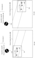
- a polarizer filter configuration may be determined based on where a specular surface is displayed on a screen.
- FIGs. 8A and 8B schematically illustrate that different screen display regions may be associated with different polarizer configurations.
- the polarizer orientation may for example be set to a desired orientation ⁇ 1
- the polarizer orientation may for example be set to a desired orientation ⁇ 2 .
- a polarizer may be configured to provide comparatively improved or optimized specular filter configurations for a selected screen region.
- a polarizer orientation may be optimized for a center screen region 523, as schematically illustrated in FIG. 9 .
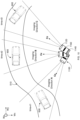
- imaging system 1000 may in some embodiments be configured to acquire and lock onto a moving platform 600 for tracking purposes.
- Platform tracking may be implemented by a plurality of cameras 1100 that are positioned in different imaging directions and/or by at least one camera 1100 that is coupled with an (e.g., gymbaled) steering mechanism for controllably steering camera 1100, for example, in three degrees of freedom.
- Tracking of vehicle 600 by camera 1100 over time is schematically illustrated by the respective different imaging directions A, B and C at corresponding time stamps t1, t2 and t3.
- the desired polarization filter configurations may be preset or predetermined for the various imaging directions A, B and C. Desired polarizer orientations may therefore already be associated with corresponding imaging directions prior to initiating tracking of vehicle 600. Hence, polarizer orientation adjustment to a desired orientation can be performed during vehicle tracking without any or with negligible latency.
- imaging system 1000 may be employed to allow characterization of scene ROIs (specular sROI) behind window buildings, glass doors, shop windows, and/or the like.
- Windows of buildings are, as noted above, examples of manmade physical characteristics of a geographical area.
- a desired polarizer orientation ⁇ 5 can be determined based on the position and orientation of a closed window of a building 10600 and of an imaging direction employed by camera 1100 within world reference coordinate system Wxyz.
- a specular and transparent surface may pertain to a water surface.
- Imaging system 1000 may thus facilitate or enable the imaging of objects immersed in water from above the water surface.
- imaging system 1000 may be operable to control an image sensor exposure time of sufficient duration and/or gain to obtain object image data allowing characterization of the specular sROI and/or of an object (e.g., a person) in the specular sROI located behind the transparent and specular surface.
- the exposure time is determined, for example, based on one or more of the following: an amount of reflected specular light that is incident onto the at least one first image sensor; an amount of sunlight incident onto a light sensor.
- imaging system 1000 may be configured to control one or more image acquisition parameter values to generate a sequence of multiplexed image frames that includes frames generated for imaging the sROI and frames generated for imaging scene portions outside the sROI.
- Image acquisition parameter values such as, for example, multiplexing parameters (e.g., frame combination sequence), number of frames assigned for readout of sROI image data and for readout of ex-sROI data, sensor gain, exposure time, sROI size, and/or ex-sROI size, may be predetermined or controlled (e.g., dynamic or adaptively) to obtain first image data allowing characterization of a specular sROI behind a specular surface and/or characterization of objects positioned in the specular sROI, and further to obtain second image data descriptive of scene portions outside the specular sROI (hereinafter: ex-sROI).
- multiplexing parameters e.g., frame combination sequence
- number of frames assigned for readout of sROI image data and for readout of ex-sROI data e.g., sensor gain, exposure time, sROI size, and/or ex-sROI size
- the image acquisition parameter values may be controlled to obtain first image information about a person seated behind a vehicle windshield, and to obtain second image information about the vehicle's license plate.
- data obtained from a plurality of first frames may be processed to obtain an image for specular sROI characterization purposes, and data obtained from at least one second frame may be used to obtain a scene portion that is outside the specular sROI.
- More image frames may be combined to obtain specular ROI image information than to obtain information about the scene portion which is outside the specular sROI.
- a plurality of consecutive or non-consecutive frames may be generated and readout for obtaining image data descriptive of the sROI
- plurality of consecutive or non-consecutive frames may be generated and readout for obtaining image data descriptive of scene portions outside the sROI.
- different sROI image acquisition parameter value may be employed for generating different sROI frames and/or different ex-sROI image acquisition parameter values may be employed for generating different ex-sROI frames.
- 10 consecutive frames may be generated and readout to obtain characterizable sROI image information
- 2 consecutive frames may be generated and readout to obtain characterizable ex-sROI image information
- a set of 5 consecutive sROI frames 13100 may be generated, which is followed by the generation of an ex-sROI frame 13200. The latter is then followed the generation of another set of 5 consecutive sROI frames 13100. The other set of five sROI frames 13100 is then followed by another ex-sROI frame.
- the two sets of sROI frames 13100 may be readout to generate characterizable sROI image information and the two ex-sROI frames 13200 may be readout to generate characterizable ex-sROI image information.
- the image acquisition parameter values may be controlled, for example, based on the amount of scene light incident onto the system's imaging sensor(s). For example, the conversion of incident light reflected from the skin of light-skinned persons into electronic signals may require less gain and/or exposure time than the conversion of incident light reflected from the skin of dark-skinned persons to allow object characterization. In another example, the conversion of incident light reflected from light-colored vehicles into electronic signals may require less gain and/or exposure time than the conversion of incident light reflected from the dark-colored vehicle.
- the image acquisition parameter values may be adaptively controlled for the imaging of sROI and ex-sROI.
- the exposure time and/or gain required to obtain specular sROI image information may be higher compared to an exposure time and/or gain required to obtain ex-sROI image information.
- the exposure time in a frame to obtain specular sROI image information may be 15 milliseconds, whereas the exposure time in a frame to obtain ex-sROI image information may be 1 millisecond.
- pixels which may be associated with ex-sROI may be overexposed to ensure sufficient photon accumulation for pixels which are largely subjected to specular reflections.
- pixels which are employed for imaging sROI information may be comparatively underexposed, for example, for the purpose of person characterization (e.g., person identification), e.g., due to the employment of the polarizer filter which may render the sROI to become comparatively dark.
- image acquisition parameter values of a frame to generate specular sROI information and of a frame to generate ex-sROI information may be predetermined.
- image acquisition parameter values of frames used to generate specular sROI information may be updated dynamically or adaptively.
- image acquisition parameter values of frames used to generate ex-sROI information may be updated dynamically or adaptively.
- Accumulating data by continuously reading out image frames improves image quality, may allow the imaging of an object from different directions and/or under different lighting conditions, thereby improving object (e.g., person) identification precision, as well as person authentication precision.
- object e.g., person
- data relating to facial features, skin texture, skin color, and/or the like may be enriched by continuously reading out of image frames.
- imaging system 1000 may further include a light power sensor 1900 for obtaining an estimate of the (e.g., average) amount of light that is incident onto image sensor 1140 from scene (e.g., ambient light) during a certain sensor exposure time. Such incident light estimate may be taken into consideration by imaging system 1000 when controlling image acquisition parameter values.
- a light power sensor 1900 for obtaining an estimate of the (e.g., average) amount of light that is incident onto image sensor 1140 from scene (e.g., ambient light) during a certain sensor exposure time.
- scene e.g., ambient light
- specular and diffusive sROI information may be generated through selective control of the operating parameters of different pixel subsets in same frame.
- the exposure time of the first sensor pixels may be set to a value such to ensure sufficient photon integration to enable sROI characterization and/or object characterization in the specular sROI.
- the same exposure time may be concurrently employed for the second sensor pixels although this may cause pixel overexposure.
- imaging system 1000 may be configured to automatically detect or determine, for a given frame, which sensor pixel is largely subjected to specular reflections and which not.
- imaging system 1000 may adaptively and selectively adjust the exposure times to enable specular sROI characterization and/or object characterization with the first sensor pixels and prevent overexposure of the second sensor pixels. This adaptive process may be performed continuously.
- the first and second exposure time durations of a first and second subset of pixels may be predetermined for imaging the specular sROI and the diffusive sROI, respectively.
- the first exposure time duration of the first subset of pixels for imaging the specular sROI may be adaptively controlled, and the second exposure time duration of the second subset of pixels for imaging the diffusive sROI may be predetermined.
- the first exposure time duration for specular sROI imaging may be predetermined and the second exposure time duration for imaging a diffusive sROI may be adaptively controlled.
- the first and the second exposure time durations of the first and second subset of pixels may be adaptively controlled.
- the first exposure time for imaging a specular sROI behind a specular surface may be shorter than the second exposure time required for imaging the remainder scene region.
- the first exposure time for imaging the specular sROI behind the specular surface may be reduced compared to the exposure time required for imaging the remainder scene portions.
- the polarization filter functionality may be disabled when imaging the sROI behind the specular surface.
- the first and second sensor pixels may be of the same sensor. In some embodiments, the first and second sensor pixels may be of different sensors. In some embodiments, the first and second sensor pixels may be of different sensors but of the same camera. In some embodiments, the first and second sensor pixels may be of sensors employed by different cameras.
- Image acquisition parameter values may be changed dynamically and/or adaptively. Dynamic image acquisition parameter values are forcefully changed, for example, periodically according to a certain clock value. Adaptive thresholds are changed in response to changes in characteristics of, for example, the scene and may vary depending on a variety of parameters.
- a first exposure time and/or gain may be employed by first camera 1100 to acquire an object located behind a transparent and specular (e.g., vehicle) surface (e.g., a windshield), while a second exposure time shorter than the first exposure time and a second gain lower than the first gain may be employed by second camera 1102 to acquire diffusive reflections pertaining to, for example, the vehicle's plate number, vehicle color, vehicle shape, etc. for vehicle characterization purposes.
- a transparent and specular e.g., vehicle
- second exposure time shorter than the first exposure time and a second gain lower than the first gain may be employed by second camera 1102 to acquire diffusive reflections pertaining to, for example, the vehicle's plate number, vehicle color, vehicle shape, etc. for vehicle characterization purposes.
- a method for acquiring images of a scene comprising a specular surface may include determining an orientation of a specular surface in the scene relative to imaging optics of a camera (block 14100).
- the method may further include determining, based on the orientation, a polarization filter orientation such that specular light reflections onto an image sensor of the camera are filtered out at least partially or completely (block 14200).
- Example 1 pertains to an imaging system configured to facilitate or enable vision through at least partially transparent and specular surfaces, comprising: at least one image acquisition device for acquiring a scene image comprising an at least partially transparent surface providing specular light reflections; the at least one image acquisition device comprising an image sensor and imaging optics having an optical axis for guiding light received from the scene along the optical axis onto the image sensor;
- Example 2 the subject matter Example 1 may optionally further include automatically determining and controlling the polarization filter orientation such that the amount of reflective surface reflected light incident onto the at least one first image sensor is reduced or minimized.
- Example 3 the subject matter of any one or any combination of Examples 1-2 may optionally further include, wherein an orientation of the at least partially transparent surface relative to the at least one first imaging optics is determined based on:
- Example 4 the subject matter of Example 3 may optionally further include, wherein the one or more platform characteristics are determined based on the one or more acquired scene images comprising the at least partially transparent surface.
- Example 5 the subject matter of any one or any combination of Examples 3-4 may optionally further include wherein the one or more platform characteristics includes a vehicle class and/or type.
- Example 6 the subject matter of any one or any combination of Examples 1-5 may optionally further include wherein the controlling of the polarization filter orientation is further based on one of the following:
- Example 7 the subject matter of any one or any combination of Examples 1-6 may optionally further include wherein the polarization filter orientation is determined without performing on-site: light polarization measurement of specular light reflections.
- Example 8 the subject matter of any one or any combination of Examples 1-7 may optionally further include wherein the polarizer filter orientation is set to a desired value for imaging a scene portion that is located behind the at least partially transparent surface such to allow characterization of the scene portion.
- Example 9 the subject matter of any one or any combination of Examples 1-8 may optionally further include wherein image acquisition parameter values used for imaging a specular region-of-interest (sROI) of a scene may differ from the imaging acquisition parameter values employed for imaging scene portions outside the sROI
- sROI specular region-of-interest
- Example 10 the subject matter of Example 9 may optionally further include wherein the image acquisition parameter values are determined based on one of the following:
- Example 11 the subject matter of Example 9 and/or 10 may optionally further include that the system is configured to controllably allow overexposure of sensor pixels which are imaging scene portions that are outside the sROI to ensure sufficient photon accumulation from the sROI.
- Example 12 the subject matter of Example 9 and/or 10 may optionally further include that the system is configured to controllably allow underexposure for the purpose of person characterization (e.g., identification) of sensor pixels subjected to light incident from the sROI to avoid overexposure of sensor pixels used for imaging scene portions which are outside the sROI.
- system is configured to controllably allow underexposure for the purpose of person characterization (e.g., identification) of sensor pixels subjected to light incident from the sROI to avoid overexposure of sensor pixels used for imaging scene portions which are outside the sROI.
- Example 13 the subject matter of any one or any combination of Example 9-12 may optionally further include wherein the system is configured to control the image acquisition parameter values to generate a sequence of multiplexed image frames that includes frames generated for imaging the sROI and frames generated for imaging scene portions outside the sROI.
- Example 14 the subject matter of any one or any combination of Example 9-13 may optionally further include wherein the image acquisition parameters values refer to one of the following: gain, exposure time, multiplexing parameters, sROI size, ex-sROI size, or any combination of the aforesaid.
- an imaging method for enabling vision through at least partially transparent and specular surfaces comprises:
- Example 17 the subject matter of Examples 15 and/or 16 may optionally further comprise wherein an orientation of the at least partially transparent surface relative to the at least one first imaging optics is determined based on:
- Example 18 the subject matter of any one or any combination of examples 15 to 17 may optionally further comprise wherein the platform characteristic is determined based on the one or more acquired scene images comprising the at least partially transparent surface.
- Example 19 the subject matter of Example 18 may optionally further comprise wherein the platform characteristic includes a vehicle class and/or type.
- Example 20 the subject matter of any one or any combination of examples 15 to 19 may optionally further comprise wherein the controlling of the polarization filter orientation is further based on one of the following:
- Example 21 the subject matter of any one or any combination of examples 15 to 20 may optionally further comprise wherein the polarization filter orientation is determined without performing on-site: light polarization measurement of specular light reflections.
- Example 23 the subject matter of any one or any combination of examples 15 to 22 may optionally further comprise wherein image acquisition parameter values used for imaging a specular region-of-interest (sROI) of a scene may differ from the imaging acquisition parameter values employed for imaging scene portions outside the sROI.
- sROI specular region-of-interest
- Example 24 the subject matter of example 23 may optionally further comprise wherein the image acquisition parameter values are determined based on one of the following: an amount of light reflected from the at least partially transparent surface and incident onto the at least one first image sensor; an amount of ambient light incident onto an additional image sensor, or both.
- Example 25 the subject matter of Examples 23 and/or 24 may optionally further comprise controllably allowing overexposure of sensor pixels which are imaging scene portions that are outside the sROI to ensure sufficient photon accumulation from the sROI.
- Example 26 the subject matter of Examples 23 and/or 24 may optionally further comprise controllably allowing underexposure for the purpose of person identification of sensor pixels subjected to light incident from the sROI to avoid overexposure of sensor pixels used for imaging scene portions which are outside the sROI.
- Example 27 the subject matter of any one or any combination of Examples 23 to 26 may optionally further comprise controlling the image acquisition parameter values to generate a sequence of multiplexed image frames that includes frames generated for imaging the sROI and frames generated for imaging scene portions outside the sROI.
- Example 28 the subject matter of any one or any combination of Examples 23 to 27 may optionally further comprise wherein the image acquisition parameters include one of the following: gain, exposure time, multiplexing parameters, sROI size, ex-sROI size, or any combination of the aforesaid.
- Example 29 pertains to an imaging system configured to reduce or prevent the effect of unwanted specular reflections reflected by specular surfaces located in a scene, comprising:
- Example 30 the subject matter of example 1 may optionally further comprise automatically determining and controlling the polarization filter orientation such that the amount of specular light reflections incident onto the at least one first image sensor is reduced or minimized.
- Example 31 the subject matter of examples 29 and/or 30 may optionally further comprise, wherein an orientation of the specular surface relative to the at least one first imaging optics is determined based on:
- Example 32 the subject matter of example 31 may optionally further comprise, wherein the one or more platform characteristics are determined based on the one or more acquired scene images comprising the specular surface.
- Example 33 the subject matter of any one or more of the Examples 29 to 32 may optionally further comprise wherein the one or more platform characteristics includes a vehicle class and/or type.
- Example 34 the subject matter of nay one or more of the Examples 29 to 33 may optionally further comprise, wherein the controlling of the polarization filter orientation is further based on one of the following:
- Example 35 the subject matter of any one or more of the Examples 29 to 34 may optionally further comprise, wherein the polarization filter orientation is determined without performing on-site: light polarization measurement of specular light reflections.
- the subject matter of any one or more of the Examples 29 to 35 may optionally further comprise, wherein the specular surface is also transparent, and the polarizer filter orientation is set to a desired value for imaging a scene portion that is located behind the transparent and specular surface such to allow characterization of the scene portion.
- Example 38 the subject matter of Example 37 may optionally further comprise, wherein the at least one image acquisition parameter value is determined based on one of the following:
- examples 37 and/or 38 may optionally further comprise, wherein the system is configured to controllably allow underexposure for the purpose of person identification of sensor pixels subjected to light incident from the sROI to avoid overexposure of sensor pixels used for imaging scene portions which are outside the sROI.
- any one or more of the examples 37 to 39 may optionally further comprise, wherein the system is configured to control the image acquisition parameter values to generate a sequence of multiplexed image frames that includes frames generated for imaging the sROI and frames generated for imaging scene portions outside the sROI.
- the subject matter of any one or more of the examples 37 to 39 to 13 may optionally further comprise, wherein the image acquisition parameters values refer to one of the following: gain, exposure time, multiplexing parameters, sROI size, ex-sROI size, or any combination of the aforesaid.
- Example 42 pertains to an imaging method for reducing or preventing the effect of unwanted specular reflections reflected by specular surfaces located in a scene, comprising:
- Example 43 the subject matter of Example 42 may optionally further comprise: automatically determining and controlling the polarization filter orientation such that the amount of specular light reflections incident onto the at least one first image sensor is reduced or minimized.
- Example 44 the subject matter of Example 42 and/or 43 may optionally further comprise wherein an orientation of the specular surface relative to the at least one first imaging optics is determined based on:
- any one or more of the Examples 42 to 44 may optionally further comprise, wherein the platform characteristic is determined based on the one or more acquired scene images comprising the specular surface.
- example 46 the subject matter of example 44 may optionally further comprise wherein the platform characteristic includes a vehicle class and/or type.
- any one or more of the examples 42 to 46 may optionally further comprise wherein the controlling of the polarization filter orientation is further based on one of the following:
- Example 48 the subject matter of any one or more of the examples 42 to 47 may optionally further comprise, wherein the polarization filter orientation is determined without performing on-site: light polarization measurement of specular light reflections.
- Example 49 the subject matter of any one or more of the examples 42 to 48 may optionally further comprise, wherein when the specular surface is also transparent, further comprising setting the polarizer filter orientation to a desired value for imaging a scene portion that is located behind the transparent and specular surface such to allow characterization of the scene portion.
- Example 50 the subject matter of example 49 may optionally further comprise, wherein the transparent and specular surface defines a specular region-of-interest (sROI); and wherein at least one image acquisition parameter value used for imaging the sROI of a scene differ from the imaging acquisition parameter values employed for imaging scene portions outside the sROI.
- sROI specular region-of-interest
- Example 51 the subject matter of example 50 may optionally further comprise wherein the at least one image acquisition parameter value is determined based on one of the following:
- Example 52 the subject matter of any one or more of the examples 50-51 may optionally further comprise controllably allowing overexposure of sensor pixels which are imaging scene portions that are outside the sROI to ensure sufficient photon accumulation from the sROI.
- Example 53 the subject matter of any one or more of the examples 50-51 may optionally further comprise controllably allowing underexposure for the purpose of person identification of sensor pixels subjected to light incident from the sROI to avoid overexposure of sensor pixels used for imaging scene portions which are outside the sROI.
- Example 53 the subject matter of any one or more of the examples 50-52 may optionally further comprise controlling the at least one image acquisition parameter value to generate a sequence of multiplexed image frames that includes frames generated for imaging the sROI and frames generated for imaging scene portions outside the sROI.
- Example 54 the subject matter of any one or more of the examples 50-53 may optionally further comprise wherein the at least one image acquisition parameter value includes one of the following: gain, exposure time, multiplexing parameters, sROI size, ex-sROI size, or any combination of the aforesaid.
- Any digital computer system, unit, device, module and/or engine exemplified herein can be configured or otherwise programmed to implement a method disclosed herein, and to the extent that the system, module and/or engine is configured to implement such a method, it is within the scope and spirit of the disclosure.
- the system, module and/or engine are programmed to perform particular functions pursuant to computer readable and executable instructions from program software that implements a method disclosed herein, it in effect becomes a special purpose computer particular to embodiments of the method disclosed herein.
- the methods and/or processes disclosed herein may be implemented as a computer program product that may be tangibly embodied in an information carrier including, for example, in a non-transitory tangible computer-readable and/or non-transitory tangible machine-readable storage device.
- the computer program product may directly loadable into an internal memory of a digital computer, comprising software code portions for performing the methods and/or processes as disclosed herein.
- a computer readable signal medium may include a propagated data signal with computer readable program code embodied therein, for example, in baseband or as part of a carrier wave. Such a propagated signal may take any of a variety of forms, including, but not limited to, electro-magnetic, optical, or any suitable combination thereof.
- a computer readable signal medium may be any computer readable medium that is not a non-transitory computer or machine-readable storage device and that can communicate, propagate, or transport a program for use by or in connection with apparatuses, systems, platforms, methods, operations and/or processes discussed herein.
- non-transitory computer-readable storage device and “non-transitory machine-readable storage device” encompasses distribution media, intermediate storage media, execution memory of a computer, and any other medium or device capable of storing for later reading by a computer program implementing embodiments of a method disclosed herein.
- a computer program product can be deployed to be executed on one computer or on multiple computers at one site or distributed across multiple sites and interconnected by one or more communication networks.
- These computer readable and executable instructions may be provided to a processor of a general purpose computer, special purpose computer, or other programmable data processing apparatus to produce a machine, such that the instructions, which execute via the processor of the computer or other programmable data processing apparatus, create means for implementing the functions/acts specified in the flowchart and/or block diagram block or blocks.
- These computer readable and executable program instructions may also be stored in a computer readable storage medium that can direct a computer, a programmable data processing apparatus, and/or other devices to function in a particular manner, such that the computer readable storage medium having instructions stored therein comprises an article of manufacture including instructions which implement aspects of the function/act specified in the flowchart and/or block diagram block or blocks.
- the computer readable and executable instructions may also be loaded onto a computer, other programmable data processing apparatus, or other device to cause a series of operational steps to be performed on the computer, other programmable apparatus or other device to produce a computer implemented process, such that the instructions which execute on the computer, other programmable apparatus, or other device implement the functions/acts specified in the flowchart and/or block diagram block or blocks.
- the terms “substantially”, “'about” and/or “close” with respect to a magnitude or a numerical value may imply to be within an inclusive range of -10% to +10% of the respective magnitude or value.
- Coupled with can mean indirectly or directly “coupled with”.
- the method may include is not limited to those diagrams or to the corresponding descriptions.
- the method may include additional or even fewer processes or operations in comparison to what is described in the figures.
- embodiments of the method are not necessarily limited to the chronological order as illustrated and described herein.
- Discussions herein utilizing terms such as, for example, “processing”, “computing”, “calculating”, “determining”, “establishing”, “analyzing”, “checking”, “estimating”, “deriving”, “selecting”, “inferring” or the like, may refer to operation(s) and/or process(es) of a computer, a computing platform, a computing system, or other electronic computing device, that manipulate and/or transform data represented as physical (e.g., electronic) quantities within the computer's registers and/or memories into other data similarly represented as physical quantities within the computer's registers and/or memories or other information storage medium that may store instructions to perform operations and/or processes.
- the term determining may, where applicable, also refer to "heuristically determining”.
- each of the verbs, "comprise” “include” and “have”, and conjugates thereof, are used to indicate that the data portion or data portions of the verb are not necessarily a complete listing of components, elements or parts of the subject or subjects of the verb.
- the use of the expression “and/or” between the last two members of a list of options for selection indicates that a selection of one or more of the listed options is appropriate and may be made. Further, the use of the expression “and/or” may be used interchangeably with the expressions “at least one of the following", “any one of the following” or “one or more of the following”, followed by a listing of the various options.
- the phrase "A,B,C, or any combination of the aforesaid” should be interpreted as meaning all of the following: (i) A or B or C or any combination of A, B, and C, (ii) at least one of A, B, and C; (iii) A, and/or B and/or C, and (iv) A, B and/or C.
- the phrase A, B and/or C can be interpreted as meaning A, B or C.
- the phrase A, B or C should be interpreted as meaning "selected from the group consisting of A, B and C". This concept is illustrated for three elements (i.e., A,B,C), but extends to fewer and greater numbers of elements (e.g., A, B, C, D, etc.).
- Real-time generally refers to the updating of information at essentially the same rate as the data is received. More specifically, in the context of the present invention "real-time” is intended to mean that the image data is acquired, processed, and transmitted from a sensor at a high enough data rate and at a low enough time delay that when the data is displayed, data portions presented and/or displayed in the visualization move smoothly without user-noticeable judder, latency or lag.
- a machine “operable to” perform a task can in some embodiments, embrace a mere capability (e.g., “modified”) to perform the function and, in some other embodiments, a machine that is actually made (e.g., "configured”) to perform the function.
- range format is merely for convenience and brevity and should not be construed as an inflexible limitation on the scope of the embodiments. Accordingly, the description of a range should be considered to have specifically disclosed all the possible subranges as well as individual numerical values within that range. For example, description of a range such as from 1 to 6 should be considered to have specifically disclosed subranges such as from 1 to 3, from 1 to 4, from 1 to 5, from 2 to 4, from 2 to 6, from 3 to 6 etc., as well as individual numbers within that range, for example, 1, 2, 3, 4, 5, and 6. This applies regardless of the breadth of the range.
Landscapes
- Physics & Mathematics (AREA)
- General Physics & Mathematics (AREA)
- Optics & Photonics (AREA)
- Engineering & Computer Science (AREA)
- Multimedia (AREA)
- Theoretical Computer Science (AREA)
- Software Systems (AREA)
- Signal Processing (AREA)
- Studio Devices (AREA)
- Cameras In General (AREA)
Claims (15)
- Bildgebungssystem (1000), das zum Verringern oder Verhindern der Wirkung unerwünschter Spiegelreflexionen, die von spiegelnden Oberflächen in einer Szene reflektiert werden, konfiguriert ist, umfassend:mindestens eine Bildaufnahmevorrichtung zum Erhalten eines Szenenbildes, das eine spiegelnde Oberfläche (610) umfasst, die spiegelnde Lichtreflexionen bereitstellt;wobei die mindestens eine Bildaufnahmevorrichtung mindestens einen ersten Bildsensor und eine Bildgebungsoptik mit einer optischen Achse zum Leiten von Licht, das von der Szene empfangen wird, entlang der optischen Achse auf den mindestens einen ersten Bildsensor umfasst;mindestens einen Polarisationsfilter (1160), der zwischen dem mindestens einen ersten Bildsensor und einem Objekt betriebsmäßig angeordnet ist;einen Prozessor (1200) und einen Speicher (1300), die so konfiguriert sind, dass sie Folgendes durchführen:Bestimmen einer Ausrichtung der spiegelnden Oberfläche relativ zu der optischen Achse der Bildgebungsoptik; undbasierend auf der Ausrichtung der Oberfläche relativ zu der optischen Achse der Bildgebungsoptik, Bestimmen einer Polarisationsfilterausrichtung, so dass eine Menge an spiegelnden Lichtreflexionen, die auf den mindestens einen ersten Bildsensor einfallen, verringert oder eliminiert wird.
- Bildgebungssystem nach Anspruch 1, ferner umfassend:
automatisches Bestimmen und Steuern der Ausrichtung der Polarisationsfilter, so dass die Menge der auf den mindestens einen ersten Bildsensor einfallenden spiegelnden Lichtreflexionen verringert oder eliminiert wird. - Bildgebungssystem nach Anspruch 1 oder Anspruch 2, wobei eine Ausrichtung der spiegelnden Oberfläche relativ zu der mindestens einen ersten Bildgebungsoptik basierend auf Folgendem bestimmt wird:einem oder mehreren Merkmalen eines geografischen Bereichs, in dem sich der Bildsensor und das Objekt befinden;einem oder mehreren Merkmalen einer Plattform, die die spiegelnde Oberfläche umfasst;Umgebungsbedingungen, einschließlich Umgebungslichtbedingungen zum Zeitpunkt des Erhaltens des Szenenbildes;einer Tageszeit, zu der das Szenenbild erhalten wird; odereiner beliebigen Kombination der vorgenannten,wobei beispielsweise das eine oder die mehreren Plattformmerkmale basierend auf dem einen oder den mehreren erhaltenen Szenenbildern, die die spiegelnde Oberfläche umfassen, bestimmt werden;wobei beispielsweise das eine oder die mehreren Plattformmerkmale eine Fahrzeugklasse und/oder einen Fahrzeugtyp einschließen.
- Bildgebungssystem nach einem oder mehreren der vorhergehenden Ansprüche, wobei das Steuern einer Ausrichtung der Polarisationsfilter ferner auf einem der Folgenden basiert:einer Position und Ausrichtung der spiegelnden Oberfläche in einem Referenzrahmen; undeiner Position und Bildgebungsrichtung des mindestens einen ersten Sensors der Bildaufnahmevorrichtung in dem Referenzrahmen.
- Bildgebungssystem nach einem oder mehreren der vorhergehenden Ansprüche, wobei die Ausrichtung des Polarisationsfilters vor Ort ohne das Durchführen von Folgendem bestimmt wird:
einer Lichtpolarisationsmessung von spiegelnden Lichtreflexionen. - Bildgebungssystem nach einem oder mehreren der vorhergehenden Ansprüche, wobei die spiegelnde Oberfläche auch transparent ist und die Ausrichtung des Polarisationsfilters auf einen gewünschten Wert eingestellt wird, um einen Abschnitt der Szene abzubilden, der sich hinter der transparenten und spiegelnden Oberfläche befindet, um eine Kennzeichnung des Abschnitts der Szene zuzulassen;wobei beispielsweise die transparente und spiegelnde Oberfläche eine spiegelnde Region von Interesse (sROI) definiert, undwobei mindestens ein Bildaufnahmeparameterwert, der für die Bildgebung der sROI verwendet wird, sich von dem mindestens einen Bildaufnahmeparameterwert unterscheidet, der für die Bildgebung von Szenenabschnitten außerhalb der sROI verwendet wird; undwobei beispielsweise der mindestens eine Bildaufnahmeparameterwert basierend auf einem der folgenden bestimmt wird:einer Menge an Licht, das von der transparenten und spiegelnden Oberfläche reflektiert wird und auf den mindestens einen ersten Bildsensor einfällt;einer Menge an Umgebungslicht, das auf einen zusätzlichen Bildsensor einfällt, oder beidem.
- Bildgebungssystem nach Anspruch 6, das ferner so konfiguriert ist, dass es eine kontrollierbare Überbelichtung der Sensorpixel zulässt, die außerhalb der sROI liegende Abschnitte der Bildgebungsszene darstellen, um eine ausreichende Photonensammlung von der sROI sicherzustellen;wobei das Bildgebungssystem beispielsweise so konfiguriert ist, dass es den mindestens einen Bildaufnahmeparameterwert steuert, um eine Sequenz von gemultiplexten Bildrahmen zu erzeugen, die Rahmen einschließt, die für die Bildgebung der sROI erzeugt wurden, und Rahmen, die für die Bildgebung von Abschnitten der Szene außerhalb der sROI erzeugt wurden;wobei der mindestens eine Bildaufnahmeparameterwert beispielsweise auf einen der folgenden Werte Bezug nimmt: Verstärkung, Belichtungszeit, Multiplexing-Parameter, Größe der sROI, Größe der ex-sROI oder eine beliebige Kombination der vorgenannten Werte.
- Bildgebungssystem nach Anspruch 6, das ferner so konfiguriert ist, dass es zum Zweck einer Personenidentifizierung eine kontrollierbare Unterbelichtung von Sensorpixeln zulässt, die einem von der sROI einfallenden Licht ausgesetzt sind, um eine Überbelichtung von Sensorpixeln zu vermeiden, die zur Bildgebung von außerhalb der sROI liegenden Szenenabschnitten verwendet werden;wobei das Bildgebungssystem beispielsweise so konfiguriert ist, dass es den mindestens einen Bildaufnahmeparameterwert steuert, um eine Sequenz von gemultiplexten Bildrahmen zu erzeugen, die Rahmen, die für die Bildgebung der sROI erzeugt wurden, und Rahmen, die zur Bildgebung von außerhalb der sROI liegenden Szenenabschnitten erzeugt wurden, einschließt; undwobei der mindestens eine Bildaufnahmeparameterwert beispielsweise auf einen der folgenden Werte Bezug nimmt: Verstärkung, Belichtungszeit, Multiplexing-Parameter, Größe der sROI, Größe der ex-sROI oder eine beliebige Kombination der vorgenannten Werte.
- Bildgebungsverfahren zum Verringern oder Verhindern der Wirkung unerwünschter Spiegelreflexionen, die von spiegelnden Oberflächen in einer Szene reflektiert werden, umfassend:Erhalten, durch mindestens eine Bildaufnahmevorrichtung, die eine optische Achse aufweist, eines Szenenbildes, das eine spiegelnde Oberfläche umfasst, die spiegelnde Lichtreflexionen bereitstellt;Bestimmen einer Ausrichtung der spiegelnden Oberfläche relativ zu der optischen Achse der Bildgebungsoptik; undbasierend auf der Ausrichtung der spiegelnden Oberfläche relativ zu der optischen Achse der Bildgebungsoptik, Bestimmen einer Ausrichtung der Polarisationsfilter, so dass eine Menge an spiegelnden Lichtreflexionen, die auf mindestens einen ersten Bildsensor einfallen, verringert oder eliminiert wird.
- Verfahren nach Anspruch 9, das ferner Folgendes umfasst:
automatisches Bestimmen und Steuern der Ausrichtung der Polarisationsfilter, so dass die Menge von auf den mindestens einen ersten Bildsensor einfallenden spiegelnden Lichtreflexionen verringert oder eliminiert wird. - Verfahren nach Anspruch 9 oder Anspruch 10, wobei eine Ausrichtung der spiegelnden Oberfläche relativ zu der mindestens einen ersten Bildgebungsoptik basierend auf Folgendem bestimmt wird:einem oder mehreren Merkmalen eines geografischen Bereichs, in dem sich der Bildsensor und das Objekt befinden;einer Ausrichtung der Plattform oder der spiegelnden Oberfläche in der Szene;Umgebungsbedingungen, einschließlich Umgebungslichtbedingungen zum Zeitpunkt des Erhaltens des Szenenbildes;einer Tageszeit, zu der ein Szenenbild erhalten wird; odereiner beliebigen Kombination der vorgenannten.
- Verfahren nach einem oder mehreren der Ansprüche 9 bis 11, wobei das Plattformmerkmal basierend auf dem einen oder den mehreren erhaltenen Szenenbildern, die die spiegelnde Oberfläche umfassen, bestimmt wird; wobei das Plattformmerkmal beispielsweise eine Fahrzeugklasse und/oder einen Fahrzeugtyp einschließt.
- Verfahren nach einem oder mehreren der Ansprüche 9 bis 12, wobei das Steuern der Ausrichtung der Polarisationsfilter ferner auf einem der Folgenden basiert:einer Position und Ausrichtung der spiegelnden Oberfläche in einem Referenzrahmen; undeiner Position und Bildgebungsrichtung des mindestens einen ersten Sensors der Bildaufnahmevorrichtung in dem Referenzrahmen.
- Verfahren nach einem oder mehreren der Ansprüche 9 bis 13, wobei, wenn die spiegelnde Oberfläche auch transparent ist, das Verfahren ferner das Einstellen der Ausrichtung des Polarisationsfilters auf einen gewünschten Wert umfasst, um einen Abschnitt der Szene abzubilden, der sich hinter der transparenten und spiegelnden Oberfläche befindet, um die Kennzeichnung des Abschnitts der Szene zuzulassen;wobei, beispielsweise, die transparente und spiegelnde Oberfläche eine spiegelnde Region von Interesse (sROI) definiert, wobei mindestens ein Bildaufnahmeparameterwert, der für die Bildgebung der sROI einer Szene verwendet wird, sich von dem mindestens einen Bildaufnahmeparameterwert unterscheidet, der für die Bildgebung von Szenenabschnitten außerhalb der sROI verwendet wird;wobei beispielsweise der mindestens eine Bildaufnahmeparameterwert basierend auf einem der Folgenden bestimmt wird: einer Menge an Licht, das von der transparenten und spiegelnden Oberfläche reflektiert wird und auf den mindestens einen ersten Bildsensor einfällt, einer Menge an Umgebungslicht, das auf einen zusätzlichen Bildsensor einfällt, oder beidem;wobei das Verfahren beispielsweise das Zulassen einer kontrollierbaren Überbelichtung von Sensorpixeln umfasst, die außerhalb der sROI liegende Abschnitte der Bildgebungsszene sind, um eine ausreichende Photonensammlung von der sROI sicherzustellen;wobei das Verfahren beispielsweise ferner zum Zweck einer Personenidentifizierung das Zulassen einer kontrollierbaren Unterbelichtung von Sensorpixeln umfasst, die einem von der sROI einfallenden Licht ausgesetzt sind, um eine Überbelichtung von Sensorpixeln zu vermeiden, die zur Bildgebung von außerhalb der sROI liegenden Abschnitten verwendet werden;wobei das Verfahren beispielsweise das Steuern des mindestens einen Bildaufnahmeparameterwerts umfasst, um eine Sequenz von gemultiplexten Bildrahmen zu erzeugen, die Rahmen, die für die Bildgebung der sROI erzeugt wurden, und Rahmen, die zur Bildgebung von außerhalb der sROI liegenden Abschnitten erzeugt wurden, einschließt;wobei, beispielsweise, der mindestens eine Bildaufnahmeparameter einen der folgenden Werte einschließt: Verstärkung, Belichtungszeit, Multiplexing-Parameter, Größe der sROI, Größe der ex-sROI oder eine beliebige Kombination der vorgenannten Werte.
- Verfahren nach Anspruch 14, wobei der mindestens eine Bildaufnahmeparameter einen der folgenden Werte einschließt:
Verstärkung, Belichtungszeit, Multiplexing-Parameter, Größe der sROI, Größe der ex-sROI oder eine beliebige Kombination der vorgenannten.
Applications Claiming Priority (2)
| Application Number | Priority Date | Filing Date | Title |
|---|---|---|---|
| IL279275A IL279275A (en) | 2020-12-06 | 2020-12-06 | Device, systems and methods for scene image acquisition |
| PCT/IB2021/061255 WO2022118253A1 (en) | 2020-12-06 | 2021-12-02 | Devices, systems and methods for scene image acquisition |
Publications (4)
| Publication Number | Publication Date |
|---|---|
| EP4256397A1 EP4256397A1 (de) | 2023-10-11 |
| EP4256397A4 EP4256397A4 (de) | 2024-05-29 |
| EP4256397C0 EP4256397C0 (de) | 2025-04-30 |
| EP4256397B1 true EP4256397B1 (de) | 2025-04-30 |
Family
ID=81853969
Family Applications (1)
| Application Number | Title | Priority Date | Filing Date |
|---|---|---|---|
| EP21900195.5A Active EP4256397B1 (de) | 2020-12-06 | 2021-12-02 | Vorrichtungen, systeme und verfahren zur erfassung von szenenbildern |
Country Status (4)
| Country | Link |
|---|---|
| US (1) | US11836964B2 (de) |
| EP (1) | EP4256397B1 (de) |
| IL (1) | IL279275A (de) |
| WO (1) | WO2022118253A1 (de) |
Family Cites Families (30)
| Publication number | Priority date | Publication date | Assignee | Title |
|---|---|---|---|---|
| US4257106A (en) | 1979-05-24 | 1981-03-17 | Norlin Industries, Inc. | Method and apparatus for thermal imaging |
| JPH0534641A (ja) * | 1991-07-30 | 1993-02-12 | Kimisato Kurihara | 観察装置および観察方法 |
| US5406938A (en) | 1992-08-24 | 1995-04-18 | Ethicon, Inc. | Glare elimination device |
| US6714665B1 (en) * | 1994-09-02 | 2004-03-30 | Sarnoff Corporation | Fully automated iris recognition system utilizing wide and narrow fields of view |
| JPH10145668A (ja) | 1996-11-14 | 1998-05-29 | Nikon Corp | 偏光フィルタ制御機構 |
| US6411749B2 (en) * | 2000-05-11 | 2002-06-25 | Micro-Optice, Inc. | In-line fiber optic polarization combiner/divider |
| US20030103261A1 (en) * | 2001-01-09 | 2003-06-05 | Ranald Hay | Techniques for reducing observed glare by using polarized optical transmission & reception devices |
| WO2002073514A2 (en) | 2001-03-08 | 2002-09-19 | Moore North America, Inc. | Method and apparatus for reducing specular reflection from a scannable surface |
| US7561312B1 (en) | 2004-10-04 | 2009-07-14 | Google Inc. | Systems and methods for glare removal using polarized filtering in document scanning |
| US7872666B2 (en) | 2005-12-22 | 2011-01-18 | Robert Bosch Gmbh | Automatic polarizer for CCTV applications |
| JP4077869B2 (ja) * | 2006-05-29 | 2008-04-23 | 松下電器産業株式会社 | 光源推定装置、光源推定システムおよび光源推定方法、並びに、画像高解像度化装置および画像高解像度化方法 |
| US7729607B2 (en) | 2006-05-31 | 2010-06-01 | Technologies4All, Inc. | Camera glare reduction system and method |
| FR2927179B1 (fr) * | 2008-02-01 | 2010-11-26 | Solystic | Systeme d'acquisition d'images pour l'identification de signes sur des envois postaux. |
| WO2010073547A1 (ja) * | 2008-12-25 | 2010-07-01 | パナソニック株式会社 | 画像処理装置及び擬似立体画像生成装置 |
| JP2011040839A (ja) * | 2009-08-07 | 2011-02-24 | Nikon Corp | 光学装置及びデジタルカメラ |
| US8964072B2 (en) | 2010-02-25 | 2015-02-24 | Vorotec Ltd. | Light filter with varying polarization angles and processing algorithm |
| US20110228115A1 (en) * | 2010-03-16 | 2011-09-22 | Microsoft Corporation | Large Format Digital Camera |
| US9060110B2 (en) * | 2011-10-07 | 2015-06-16 | Canon Kabushiki Kaisha | Image capture with tunable polarization and tunable spectral sensitivity |
| WO2013090843A1 (en) | 2011-12-15 | 2013-06-20 | Trygger Llc | Rotatable light filter assembly for camera built in a smartphone |
| US9737209B2 (en) * | 2013-05-15 | 2017-08-22 | The Johns Hopkins University | Eye tracking and gaze fixation detection systems, components and methods using polarized light |
| US9106840B2 (en) * | 2013-11-07 | 2015-08-11 | Freescale Semiconductor Inc. | Devices having automatically adjustable polarizers and related operating methods |
| IL236114A (en) * | 2014-12-07 | 2016-04-21 | Yoav Grauer | Object detection enhancement of reflection-based imaging unit |
| JP6671872B2 (ja) * | 2015-06-22 | 2020-03-25 | キヤノン株式会社 | アダプタ装置、撮像装置および撮像システム |
| US10371519B1 (en) | 2017-05-26 | 2019-08-06 | Lockheed Martin Corporation | Polarization optical compass |
| US11158072B2 (en) * | 2018-02-02 | 2021-10-26 | Dishcraft Robotics, Inc. | Intelligent dishwashing systems and methods |
| US10334180B1 (en) * | 2018-02-26 | 2019-06-25 | Motorola Mobility Llc | Digital image capture with a polarizer at different rotation angles |
| US10921450B2 (en) * | 2019-04-24 | 2021-02-16 | Aeye, Inc. | Ladar system and method with frequency domain shuttering |
| US11036067B2 (en) * | 2019-07-23 | 2021-06-15 | Semiconductor Components Industries, Llc | Image sensor packages with tunable polarization layers |
| EP4042366A4 (de) * | 2019-10-07 | 2023-11-15 | Boston Polarimetrics, Inc. | Systeme und verfahren zur erweiterung von sensorsystemen und bildgebungssystemen mit polarisation |
| US11131934B2 (en) * | 2019-10-29 | 2021-09-28 | Waymo Llc | Non-telecentric light guide elements |
-
2020
- 2020-12-06 IL IL279275A patent/IL279275A/en unknown
-
2021
- 2021-12-02 EP EP21900195.5A patent/EP4256397B1/de active Active
- 2021-12-02 WO PCT/IB2021/061255 patent/WO2022118253A1/en not_active Ceased
-
2023
- 2023-05-30 US US18/203,300 patent/US11836964B2/en active Active
Also Published As
| Publication number | Publication date |
|---|---|
| IL279275A (en) | 2022-07-01 |
| EP4256397C0 (de) | 2025-04-30 |
| EP4256397A4 (de) | 2024-05-29 |
| EP4256397A1 (de) | 2023-10-11 |
| US11836964B2 (en) | 2023-12-05 |
| WO2022118253A1 (en) | 2022-06-09 |
| US20230306710A1 (en) | 2023-09-28 |
Similar Documents
| Publication | Publication Date | Title |
|---|---|---|
| US12250447B2 (en) | Multiple operating modes to expand dynamic range | |
| US10812735B2 (en) | Image processing device and image processing method | |
| DE112017005807B4 (de) | Bildverarbeitungsvorrichtung und Bildverarbeitungsverfahren | |
| JP6795030B2 (ja) | 撮像制御装置及び撮像制御方法、並びに撮像装置 | |
| JP7014218B2 (ja) | 画像処理装置、および画像処理方法、並びにプログラム | |
| US20100315214A1 (en) | Image processor, storage medium storing an image processing program and vehicle-mounted terminal | |
| US11772545B2 (en) | Apparatus, system and method for controlling lighting using gated imaging | |
| WO2020031970A1 (en) | Information processing device, information processing method, and program | |
| US10704957B2 (en) | Imaging device and imaging method | |
| JP6209825B2 (ja) | 視差検出装置、視差検出方法 | |
| CN111833627A (zh) | 车辆视觉范围扩展方法、装置、系统和计算机设备 | |
| WO2019163315A1 (ja) | 情報処理装置、撮像装置、及び撮像システム | |
| KR20210013044A (ko) | 정보 처리 장치, 정보 처리 방법, 촬영 장치, 조명 장치 및 이동체 | |
| US11584295B2 (en) | Dynamic lighting and sensor adjustment for occupant monitoring | |
| KR102077575B1 (ko) | 차량 운전 보조 장치 및 차량 | |
| DE112019001772T5 (de) | Bildgebungsvorrichtung | |
| CN115666987A (zh) | 信号处理设备、调光控制方法、信号处理程序和调光系统 | |
| WO2017122396A1 (ja) | 制御装置、制御方法及びプログラム | |
| JPWO2019215979A1 (ja) | 画像処理装置、車載装置、画像処理方法及びプログラム | |
| EP4256397B1 (de) | Vorrichtungen, systeme und verfahren zur erfassung von szenenbildern | |
| WO2020036057A1 (ja) | 情報処理装置、情報処理方法、プログラム、及び移動体 | |
| JP7059185B2 (ja) | 画像処理装置、画像処理方法、および撮像装置 | |
| DE112018005039T5 (de) | Signalverarbeitungsvorrichtung, signalverarbeitungsverfahren, programm und mobiler körper | |
| US20190306444A1 (en) | Imaging control apparatus and method, and vehicle | |
| CN120817004A (zh) | 用于前视和后视的电子侧视镜系统和控制方法 |
Legal Events
| Date | Code | Title | Description |
|---|---|---|---|
| STAA | Information on the status of an ep patent application or granted ep patent |
Free format text: STATUS: THE INTERNATIONAL PUBLICATION HAS BEEN MADE |
|
| PUAI | Public reference made under article 153(3) epc to a published international application that has entered the european phase |
Free format text: ORIGINAL CODE: 0009012 |
|
| STAA | Information on the status of an ep patent application or granted ep patent |
Free format text: STATUS: REQUEST FOR EXAMINATION WAS MADE |
|
| 17P | Request for examination filed |
Effective date: 20230621 |
|
| AK | Designated contracting states |
Kind code of ref document: A1 Designated state(s): AL AT BE BG CH CY CZ DE DK EE ES FI FR GB GR HR HU IE IS IT LI LT LU LV MC MK MT NL NO PL PT RO RS SE SI SK SM TR |
|
| DAV | Request for validation of the european patent (deleted) | ||
| DAX | Request for extension of the european patent (deleted) | ||
| A4 | Supplementary search report drawn up and despatched |
Effective date: 20240426 |
|
| RIC1 | Information provided on ipc code assigned before grant |
Ipc: G03B 7/18 20210101ALI20240422BHEP Ipc: G02B 26/02 20060101ALI20240422BHEP Ipc: G02B 27/28 20060101AFI20240422BHEP |
|
| GRAP | Despatch of communication of intention to grant a patent |
Free format text: ORIGINAL CODE: EPIDOSNIGR1 |
|
| STAA | Information on the status of an ep patent application or granted ep patent |
Free format text: STATUS: GRANT OF PATENT IS INTENDED |
|
| INTG | Intention to grant announced |
Effective date: 20240910 |
|
| GRAJ | Information related to disapproval of communication of intention to grant by the applicant or resumption of examination proceedings by the epo deleted |
Free format text: ORIGINAL CODE: EPIDOSDIGR1 |
|
| STAA | Information on the status of an ep patent application or granted ep patent |
Free format text: STATUS: REQUEST FOR EXAMINATION WAS MADE |
|
| GRAP | Despatch of communication of intention to grant a patent |
Free format text: ORIGINAL CODE: EPIDOSNIGR1 |
|
| STAA | Information on the status of an ep patent application or granted ep patent |
Free format text: STATUS: GRANT OF PATENT IS INTENDED |
|
| INTC | Intention to grant announced (deleted) | ||
| INTG | Intention to grant announced |
Effective date: 20250120 |
|
| GRAS | Grant fee paid |
Free format text: ORIGINAL CODE: EPIDOSNIGR3 |
|
| GRAA | (expected) grant |
Free format text: ORIGINAL CODE: 0009210 |
|
| STAA | Information on the status of an ep patent application or granted ep patent |
Free format text: STATUS: THE PATENT HAS BEEN GRANTED |
|
| AK | Designated contracting states |
Kind code of ref document: B1 Designated state(s): AL AT BE BG CH CY CZ DE DK EE ES FI FR GB GR HR HU IE IS IT LI LT LU LV MC MK MT NL NO PL PT RO RS SE SI SK SM TR |
|
| REG | Reference to a national code |
Ref country code: CH Ref legal event code: EP Ref country code: GB Ref legal event code: FG4D |
|
| REG | Reference to a national code |
Ref country code: IE Ref legal event code: FG4D |
|
| REG | Reference to a national code |
Ref country code: DE Ref legal event code: R096 Ref document number: 602021030178 Country of ref document: DE |
|
| U01 | Request for unitary effect filed |
Effective date: 20250508 |
|
| U07 | Unitary effect registered |
Designated state(s): AT BE BG DE DK EE FI FR IT LT LU LV MT NL PT RO SE SI Effective date: 20250515 |
|
| PG25 | Lapsed in a contracting state [announced via postgrant information from national office to epo] |
Ref country code: ES Free format text: LAPSE BECAUSE OF FAILURE TO SUBMIT A TRANSLATION OF THE DESCRIPTION OR TO PAY THE FEE WITHIN THE PRESCRIBED TIME-LIMIT Effective date: 20250430 |
|
| PG25 | Lapsed in a contracting state [announced via postgrant information from national office to epo] |
Ref country code: NO Free format text: LAPSE BECAUSE OF FAILURE TO SUBMIT A TRANSLATION OF THE DESCRIPTION OR TO PAY THE FEE WITHIN THE PRESCRIBED TIME-LIMIT Effective date: 20250730 Ref country code: GR Free format text: LAPSE BECAUSE OF FAILURE TO SUBMIT A TRANSLATION OF THE DESCRIPTION OR TO PAY THE FEE WITHIN THE PRESCRIBED TIME-LIMIT Effective date: 20250731 |
|
| PG25 | Lapsed in a contracting state [announced via postgrant information from national office to epo] |
Ref country code: PL Free format text: LAPSE BECAUSE OF FAILURE TO SUBMIT A TRANSLATION OF THE DESCRIPTION OR TO PAY THE FEE WITHIN THE PRESCRIBED TIME-LIMIT Effective date: 20250430 |
|
| PG25 | Lapsed in a contracting state [announced via postgrant information from national office to epo] |
Ref country code: HR Free format text: LAPSE BECAUSE OF FAILURE TO SUBMIT A TRANSLATION OF THE DESCRIPTION OR TO PAY THE FEE WITHIN THE PRESCRIBED TIME-LIMIT Effective date: 20250430 |
|
| PG25 | Lapsed in a contracting state [announced via postgrant information from national office to epo] |
Ref country code: RS Free format text: LAPSE BECAUSE OF FAILURE TO SUBMIT A TRANSLATION OF THE DESCRIPTION OR TO PAY THE FEE WITHIN THE PRESCRIBED TIME-LIMIT Effective date: 20250731 |
|
| PG25 | Lapsed in a contracting state [announced via postgrant information from national office to epo] |
Ref country code: IS Free format text: LAPSE BECAUSE OF FAILURE TO SUBMIT A TRANSLATION OF THE DESCRIPTION OR TO PAY THE FEE WITHIN THE PRESCRIBED TIME-LIMIT Effective date: 20250830 |
|
| U20 | Renewal fee for the european patent with unitary effect paid |
Year of fee payment: 5 Effective date: 20251110 |
|
| PGFP | Annual fee paid to national office [announced via postgrant information from national office to epo] |
Ref country code: GB Payment date: 20251001 Year of fee payment: 5 |
|
| PG25 | Lapsed in a contracting state [announced via postgrant information from national office to epo] |
Ref country code: SM Free format text: LAPSE BECAUSE OF FAILURE TO SUBMIT A TRANSLATION OF THE DESCRIPTION OR TO PAY THE FEE WITHIN THE PRESCRIBED TIME-LIMIT Effective date: 20250430 |
|
| PG25 | Lapsed in a contracting state [announced via postgrant information from national office to epo] |
Ref country code: CZ Free format text: LAPSE BECAUSE OF FAILURE TO SUBMIT A TRANSLATION OF THE DESCRIPTION OR TO PAY THE FEE WITHIN THE PRESCRIBED TIME-LIMIT Effective date: 20250430 |
|
| PG25 | Lapsed in a contracting state [announced via postgrant information from national office to epo] |
Ref country code: SK Free format text: LAPSE BECAUSE OF FAILURE TO SUBMIT A TRANSLATION OF THE DESCRIPTION OR TO PAY THE FEE WITHIN THE PRESCRIBED TIME-LIMIT Effective date: 20250430 |
|
| PLBE | No opposition filed within time limit |
Free format text: ORIGINAL CODE: 0009261 |
|
| STAA | Information on the status of an ep patent application or granted ep patent |
Free format text: STATUS: NO OPPOSITION FILED WITHIN TIME LIMIT |
|
| REG | Reference to a national code |
Ref country code: CH Ref legal event code: L10 Free format text: ST27 STATUS EVENT CODE: U-0-0-L10-L00 (AS PROVIDED BY THE NATIONAL OFFICE) Effective date: 20260311 |
|
| 26N | No opposition filed |
Effective date: 20260202 |