EP4255354B1 - Apparatuses for trialing a humeral head - Google Patents
Apparatuses for trialing a humeral head Download PDFInfo
- Publication number
- EP4255354B1 EP4255354B1 EP21845130.0A EP21845130A EP4255354B1 EP 4255354 B1 EP4255354 B1 EP 4255354B1 EP 21845130 A EP21845130 A EP 21845130A EP 4255354 B1 EP4255354 B1 EP 4255354B1
- Authority
- EP
- European Patent Office
- Prior art keywords
- thimble
- recess
- humeral
- stem
- indicia
- Prior art date
- Legal status (The legal status is an assumption and is not a legal conclusion. Google has not performed a legal analysis and makes no representation as to the accuracy of the status listed.)
- Active
Links
Images








Classifications
-
- A—HUMAN NECESSITIES
- A61—MEDICAL OR VETERINARY SCIENCE; HYGIENE
- A61F—FILTERS IMPLANTABLE INTO BLOOD VESSELS; PROSTHESES; DEVICES PROVIDING PATENCY TO, OR PREVENTING COLLAPSING OF, TUBULAR STRUCTURES OF THE BODY, e.g. STENTS; ORTHOPAEDIC, NURSING OR CONTRACEPTIVE DEVICES; FOMENTATION; TREATMENT OR PROTECTION OF EYES OR EARS; BANDAGES, DRESSINGS OR ABSORBENT PADS; FIRST-AID KITS
- A61F2/00—Filters implantable into blood vessels; Prostheses, i.e. artificial substitutes or replacements for parts of the body; Appliances for connecting them with the body; Devices providing patency to, or preventing collapsing of, tubular structures of the body, e.g. stents
- A61F2/02—Prostheses implantable into the body
- A61F2/30—Joints
- A61F2/46—Special tools for implanting artificial joints
- A61F2/4684—Trial or dummy prostheses
-
- A—HUMAN NECESSITIES
- A61—MEDICAL OR VETERINARY SCIENCE; HYGIENE
- A61F—FILTERS IMPLANTABLE INTO BLOOD VESSELS; PROSTHESES; DEVICES PROVIDING PATENCY TO, OR PREVENTING COLLAPSING OF, TUBULAR STRUCTURES OF THE BODY, e.g. STENTS; ORTHOPAEDIC, NURSING OR CONTRACEPTIVE DEVICES; FOMENTATION; TREATMENT OR PROTECTION OF EYES OR EARS; BANDAGES, DRESSINGS OR ABSORBENT PADS; FIRST-AID KITS
- A61F2/00—Filters implantable into blood vessels; Prostheses, i.e. artificial substitutes or replacements for parts of the body; Appliances for connecting them with the body; Devices providing patency to, or preventing collapsing of, tubular structures of the body, e.g. stents
- A61F2/02—Prostheses implantable into the body
- A61F2/30—Joints
- A61F2/40—Joints for shoulders
- A61F2/4014—Humeral heads or necks; Connections of endoprosthetic heads or necks to endoprosthetic humeral shafts
-
- A—HUMAN NECESSITIES
- A61—MEDICAL OR VETERINARY SCIENCE; HYGIENE
- A61F—FILTERS IMPLANTABLE INTO BLOOD VESSELS; PROSTHESES; DEVICES PROVIDING PATENCY TO, OR PREVENTING COLLAPSING OF, TUBULAR STRUCTURES OF THE BODY, e.g. STENTS; ORTHOPAEDIC, NURSING OR CONTRACEPTIVE DEVICES; FOMENTATION; TREATMENT OR PROTECTION OF EYES OR EARS; BANDAGES, DRESSINGS OR ABSORBENT PADS; FIRST-AID KITS
- A61F2/00—Filters implantable into blood vessels; Prostheses, i.e. artificial substitutes or replacements for parts of the body; Appliances for connecting them with the body; Devices providing patency to, or preventing collapsing of, tubular structures of the body, e.g. stents
- A61F2/02—Prostheses implantable into the body
- A61F2/30—Joints
- A61F2002/30001—Additional features of subject-matter classified in A61F2/28, A61F2/30 and subgroups thereof
- A61F2002/30003—Material related properties of the prosthesis or of a coating on the prosthesis
- A61F2002/3006—Properties of materials and coating materials
- A61F2002/3009—Transparent or translucent
-
- A—HUMAN NECESSITIES
- A61—MEDICAL OR VETERINARY SCIENCE; HYGIENE
- A61F—FILTERS IMPLANTABLE INTO BLOOD VESSELS; PROSTHESES; DEVICES PROVIDING PATENCY TO, OR PREVENTING COLLAPSING OF, TUBULAR STRUCTURES OF THE BODY, e.g. STENTS; ORTHOPAEDIC, NURSING OR CONTRACEPTIVE DEVICES; FOMENTATION; TREATMENT OR PROTECTION OF EYES OR EARS; BANDAGES, DRESSINGS OR ABSORBENT PADS; FIRST-AID KITS
- A61F2/00—Filters implantable into blood vessels; Prostheses, i.e. artificial substitutes or replacements for parts of the body; Appliances for connecting them with the body; Devices providing patency to, or preventing collapsing of, tubular structures of the body, e.g. stents
- A61F2/02—Prostheses implantable into the body
- A61F2/30—Joints
- A61F2002/30001—Additional features of subject-matter classified in A61F2/28, A61F2/30 and subgroups thereof
- A61F2002/30316—The prosthesis having different structural features at different locations within the same prosthesis; Connections between prosthetic parts; Special structural features of bone or joint prostheses not otherwise provided for
- A61F2002/30329—Connections or couplings between prosthetic parts, e.g. between modular parts; Connecting elements
- A61F2002/30331—Connections or couplings between prosthetic parts, e.g. between modular parts; Connecting elements made by longitudinally pushing a protrusion into a complementarily-shaped recess, e.g. held by friction fit
- A61F2002/30332—Conically- or frustoconically-shaped protrusion and recess
-
- A—HUMAN NECESSITIES
- A61—MEDICAL OR VETERINARY SCIENCE; HYGIENE
- A61F—FILTERS IMPLANTABLE INTO BLOOD VESSELS; PROSTHESES; DEVICES PROVIDING PATENCY TO, OR PREVENTING COLLAPSING OF, TUBULAR STRUCTURES OF THE BODY, e.g. STENTS; ORTHOPAEDIC, NURSING OR CONTRACEPTIVE DEVICES; FOMENTATION; TREATMENT OR PROTECTION OF EYES OR EARS; BANDAGES, DRESSINGS OR ABSORBENT PADS; FIRST-AID KITS
- A61F2/00—Filters implantable into blood vessels; Prostheses, i.e. artificial substitutes or replacements for parts of the body; Appliances for connecting them with the body; Devices providing patency to, or preventing collapsing of, tubular structures of the body, e.g. stents
- A61F2/02—Prostheses implantable into the body
- A61F2/30—Joints
- A61F2002/30001—Additional features of subject-matter classified in A61F2/28, A61F2/30 and subgroups thereof
- A61F2002/30316—The prosthesis having different structural features at different locations within the same prosthesis; Connections between prosthetic parts; Special structural features of bone or joint prostheses not otherwise provided for
- A61F2002/30329—Connections or couplings between prosthetic parts, e.g. between modular parts; Connecting elements
- A61F2002/30331—Connections or couplings between prosthetic parts, e.g. between modular parts; Connecting elements made by longitudinally pushing a protrusion into a complementarily-shaped recess, e.g. held by friction fit
- A61F2002/30362—Connections or couplings between prosthetic parts, e.g. between modular parts; Connecting elements made by longitudinally pushing a protrusion into a complementarily-shaped recess, e.g. held by friction fit with possibility of relative movement between the protrusion and the recess
- A61F2002/30364—Rotation about the common longitudinal axis
-
- A—HUMAN NECESSITIES
- A61—MEDICAL OR VETERINARY SCIENCE; HYGIENE
- A61F—FILTERS IMPLANTABLE INTO BLOOD VESSELS; PROSTHESES; DEVICES PROVIDING PATENCY TO, OR PREVENTING COLLAPSING OF, TUBULAR STRUCTURES OF THE BODY, e.g. STENTS; ORTHOPAEDIC, NURSING OR CONTRACEPTIVE DEVICES; FOMENTATION; TREATMENT OR PROTECTION OF EYES OR EARS; BANDAGES, DRESSINGS OR ABSORBENT PADS; FIRST-AID KITS
- A61F2/00—Filters implantable into blood vessels; Prostheses, i.e. artificial substitutes or replacements for parts of the body; Appliances for connecting them with the body; Devices providing patency to, or preventing collapsing of, tubular structures of the body, e.g. stents
- A61F2/02—Prostheses implantable into the body
- A61F2/30—Joints
- A61F2002/30001—Additional features of subject-matter classified in A61F2/28, A61F2/30 and subgroups thereof
- A61F2002/30316—The prosthesis having different structural features at different locations within the same prosthesis; Connections between prosthetic parts; Special structural features of bone or joint prostheses not otherwise provided for
- A61F2002/30535—Special structural features of bone or joint prostheses not otherwise provided for
- A61F2002/30565—Special structural features of bone or joint prostheses not otherwise provided for having spring elements
-
- A—HUMAN NECESSITIES
- A61—MEDICAL OR VETERINARY SCIENCE; HYGIENE
- A61F—FILTERS IMPLANTABLE INTO BLOOD VESSELS; PROSTHESES; DEVICES PROVIDING PATENCY TO, OR PREVENTING COLLAPSING OF, TUBULAR STRUCTURES OF THE BODY, e.g. STENTS; ORTHOPAEDIC, NURSING OR CONTRACEPTIVE DEVICES; FOMENTATION; TREATMENT OR PROTECTION OF EYES OR EARS; BANDAGES, DRESSINGS OR ABSORBENT PADS; FIRST-AID KITS
- A61F2/00—Filters implantable into blood vessels; Prostheses, i.e. artificial substitutes or replacements for parts of the body; Appliances for connecting them with the body; Devices providing patency to, or preventing collapsing of, tubular structures of the body, e.g. stents
- A61F2/02—Prostheses implantable into the body
- A61F2/30—Joints
- A61F2002/30001—Additional features of subject-matter classified in A61F2/28, A61F2/30 and subgroups thereof
- A61F2002/30316—The prosthesis having different structural features at different locations within the same prosthesis; Connections between prosthetic parts; Special structural features of bone or joint prostheses not otherwise provided for
- A61F2002/30535—Special structural features of bone or joint prostheses not otherwise provided for
- A61F2002/30565—Special structural features of bone or joint prostheses not otherwise provided for having spring elements
- A61F2002/30571—Leaf springs
-
- A—HUMAN NECESSITIES
- A61—MEDICAL OR VETERINARY SCIENCE; HYGIENE
- A61F—FILTERS IMPLANTABLE INTO BLOOD VESSELS; PROSTHESES; DEVICES PROVIDING PATENCY TO, OR PREVENTING COLLAPSING OF, TUBULAR STRUCTURES OF THE BODY, e.g. STENTS; ORTHOPAEDIC, NURSING OR CONTRACEPTIVE DEVICES; FOMENTATION; TREATMENT OR PROTECTION OF EYES OR EARS; BANDAGES, DRESSINGS OR ABSORBENT PADS; FIRST-AID KITS
- A61F2/00—Filters implantable into blood vessels; Prostheses, i.e. artificial substitutes or replacements for parts of the body; Appliances for connecting them with the body; Devices providing patency to, or preventing collapsing of, tubular structures of the body, e.g. stents
- A61F2/02—Prostheses implantable into the body
- A61F2/30—Joints
- A61F2002/30001—Additional features of subject-matter classified in A61F2/28, A61F2/30 and subgroups thereof
- A61F2002/30316—The prosthesis having different structural features at different locations within the same prosthesis; Connections between prosthetic parts; Special structural features of bone or joint prostheses not otherwise provided for
- A61F2002/30535—Special structural features of bone or joint prostheses not otherwise provided for
- A61F2002/30604—Special structural features of bone or joint prostheses not otherwise provided for modular
-
- A—HUMAN NECESSITIES
- A61—MEDICAL OR VETERINARY SCIENCE; HYGIENE
- A61F—FILTERS IMPLANTABLE INTO BLOOD VESSELS; PROSTHESES; DEVICES PROVIDING PATENCY TO, OR PREVENTING COLLAPSING OF, TUBULAR STRUCTURES OF THE BODY, e.g. STENTS; ORTHOPAEDIC, NURSING OR CONTRACEPTIVE DEVICES; FOMENTATION; TREATMENT OR PROTECTION OF EYES OR EARS; BANDAGES, DRESSINGS OR ABSORBENT PADS; FIRST-AID KITS
- A61F2/00—Filters implantable into blood vessels; Prostheses, i.e. artificial substitutes or replacements for parts of the body; Appliances for connecting them with the body; Devices providing patency to, or preventing collapsing of, tubular structures of the body, e.g. stents
- A61F2/02—Prostheses implantable into the body
- A61F2/30—Joints
- A61F2002/30001—Additional features of subject-matter classified in A61F2/28, A61F2/30 and subgroups thereof
- A61F2002/30316—The prosthesis having different structural features at different locations within the same prosthesis; Connections between prosthetic parts; Special structural features of bone or joint prostheses not otherwise provided for
- A61F2002/30535—Special structural features of bone or joint prostheses not otherwise provided for
- A61F2002/30617—Visible markings for adjusting, locating or measuring
-
- A—HUMAN NECESSITIES
- A61—MEDICAL OR VETERINARY SCIENCE; HYGIENE
- A61F—FILTERS IMPLANTABLE INTO BLOOD VESSELS; PROSTHESES; DEVICES PROVIDING PATENCY TO, OR PREVENTING COLLAPSING OF, TUBULAR STRUCTURES OF THE BODY, e.g. STENTS; ORTHOPAEDIC, NURSING OR CONTRACEPTIVE DEVICES; FOMENTATION; TREATMENT OR PROTECTION OF EYES OR EARS; BANDAGES, DRESSINGS OR ABSORBENT PADS; FIRST-AID KITS
- A61F2/00—Filters implantable into blood vessels; Prostheses, i.e. artificial substitutes or replacements for parts of the body; Appliances for connecting them with the body; Devices providing patency to, or preventing collapsing of, tubular structures of the body, e.g. stents
- A61F2/02—Prostheses implantable into the body
- A61F2/30—Joints
- A61F2/40—Joints for shoulders
- A61F2/4014—Humeral heads or necks; Connections of endoprosthetic heads or necks to endoprosthetic humeral shafts
- A61F2002/4037—Connections of heads to necks
-
- A—HUMAN NECESSITIES
- A61—MEDICAL OR VETERINARY SCIENCE; HYGIENE
- A61F—FILTERS IMPLANTABLE INTO BLOOD VESSELS; PROSTHESES; DEVICES PROVIDING PATENCY TO, OR PREVENTING COLLAPSING OF, TUBULAR STRUCTURES OF THE BODY, e.g. STENTS; ORTHOPAEDIC, NURSING OR CONTRACEPTIVE DEVICES; FOMENTATION; TREATMENT OR PROTECTION OF EYES OR EARS; BANDAGES, DRESSINGS OR ABSORBENT PADS; FIRST-AID KITS
- A61F2/00—Filters implantable into blood vessels; Prostheses, i.e. artificial substitutes or replacements for parts of the body; Appliances for connecting them with the body; Devices providing patency to, or preventing collapsing of, tubular structures of the body, e.g. stents
- A61F2/02—Prostheses implantable into the body
- A61F2/30—Joints
- A61F2/40—Joints for shoulders
- A61F2/4014—Humeral heads or necks; Connections of endoprosthetic heads or necks to endoprosthetic humeral shafts
- A61F2002/4044—Connections of necks to shafts
Definitions
- This document pertains generally, but not by way of limitation, to apparatuses and methods for performing arthroplasty procedures. More particularly, this disclosure relates to, but not by way of limitation, intra-operative planning techniques for selecting the position of a prosthetic device component for a patient into which the prosthetic device component will be implanted.
- a shoulder joint comprises the juncture of the scapula, the clavicle and the humerus.
- the head of the humerus fits into a shallow socket of the scapula called the glenoid fossa to form a mobile joint.
- the humeral head moves in the glenoid fossa to provide a wide range of motion.
- the shoulder joint may suffer from various maladies including rheumatoid arthritis, osteoarthritis, rotator cuff arthropathy, avascular necrosis, bone fracture or failure of previous joint implants. If severe joint damage occurs and no other means of treatment is found to be effective, then shoulder reconstruction may be necessary.
- a shoulder joint prosthesis generally includes the replacement of the ball (glenosphere) of the humerus and, optionally, the socket (glenoid) of the shoulder blade with specially designed artificial components.
- the bio-kinematics, and thus the range of motion in the shoulder vary greatly among prospective patients for reconstruction shoulder surgery.
- the humeral component typically can have a metal shaft or stem with a body portion that can be embedded in the resected humerus and a generally hemispherical head portion supported on the stem. The head portion can slidingly engage a glenoid implant on the glenoid fossa.
- shoulder prostheses are generally available as either unitary structures or modular components.
- unitary shoulder prosthesis a large inventory of differently sized prostheses must sometimes be maintained to accommodate the different bone sizes and joint configurations of the prospective patients.
- the patient can typically be evaluated by X-ray to determine approximate sizes of prostheses needed for reconstruction.
- a number of differently sized prostheses can be selected as possible candidates based upon this preliminary evaluation.
- Final selection of the appropriately sized prosthesis can be made during the surgery.
- each design can represent a compromise that is unable to achieve all of the natural range of motion of a healthy shoulder joint because of the fixed geometric configuration in their design.
- humeral head trialing devices are described in U.S. Pat. No. 8,647,387 to Winslow , U.S. Pat. No. 7,431,736 to Maroney et al. , U.S. Pat. No. 6,736,852 to Callaway et al. , U.S. Pat. No. 6,673,114 to Hartdegen et al. , U.S. Pub. No. 2016/0030187 to Sperling et al. , U.S. Pat. Pub. No. 2011/060418 A1 to Bailey et al. , and EP Pat. Pub. No. 2,668,930 A1 to Howmedica Ostenoics Corp .
- FIGS. 7B-7D show a distal side (also called a bone facing or stem facing side) of the thimble 38.
- the thimble 38 includes a distal surface 64, a recess 66, one or more fingers 68 and a recess 69.
- a plurality of indicia 146 are located on a distal surface 152 and/or a recess 150 of the body 136 and can be visible through the body 136 from a side opposing the distal surface 152.
- Thimble 138 can differ from the thimble 38 in that the head 43 can be a slot 142, for example.
- Thimble 138 can be made of any suitable biocompatible material (e.g., metal, metal alloy such as titanium or titanium alloy, polymer, etc.).
- Thimble 138 need not be translucent or transparent, although the thimble can be translucent or transparent according to some examples.
- FIGS. 11A-11E show a method for positioning a prosthetic head component with a prosthetic stem relative to a bone. This method can be performed using one of the humeral trial apparatuses described and illustrated previously herein.
- FIG. 11A shows the driver 48 being utilized with one of the humeral trial apparatus 35 or 135.
- the driver 48 can be rotated to rotate the thimble relative to the body 36, 136 and the humeral stem (not shown).
- the surgeon may place a hand on the body 36, 136 during rotation of the thimble to discourage the body 36, 136 from co-rotating with the thimble.
- the thimble 38, 138 can be rotated until a perimeter (e.g., perimeter 41) of the body 36, 136 substantially matches that of the edge 22 of the humerus bone H as shown in FIG. 11B .
- FIG. 11B shows the surgeon can start with the indicia 62 of the thimble 38, 138 aligned with the one of the indicia 46, 146 labeled "C".
- the thimble 38, 138 can then be rotated as shown in FIG. 11A to match the edge 22 of the humerus bone H.
- This can change the relative positions of the body 36, 136 and the thimble 38, 138.
- the thimble 38, 138 can be rotated to the "D and 1 ⁇ 2" position shown in FIG. 11B .
- an amount of maximum offset from the edge 22 can be determined and noted if desired.
- the indicia 62 of the thimble 38, 138 can be extrapolated linearly outward (indicated with dashed line in FIG. 11B ) to the edge 22 and the bone (such as the edge 22) can be marked with a mark 199 as illustrated in FIG. 11B using known methods.
- the humeral head 18 can be placed in into an impactor tray.
- the stem adapter 24 can have a body 200 configured to engage the humeral head 18.
- the stem adaptor 24 can have a neck 202 configured to engage the humeral stem 30 ( FIGS. 2 , 3 and 5 ).
- the stem adaptor 24 can be selected and can have an indicia 204 thereon.
- the indicia 204 can be configured in a similar or identical manner to the indicia 62 of the thimble 38, 138. For example, both can be lines.
- the humeral head 18 can have a plurality of indicia 206.
- the indicia 204 can be used with the plurality of indicia 206 as shown in FIGS. 11C and 11D .
- the plurality of indicia 206 can be configured in a same or similar manner to the indicia 46, 146 of the body 36, 136.
- the plurality of indicia 206 can be identical to (i.e. each can be circumferentially arranged about a centerline axis of the humeral head 18, can be identically spaced and positioned, etc.) to the indicia 46, 146 of the body 36, 136.
- the body 36, 136 can have the plurality of indicia 46, 146 configured in an identical manner to those of the plurality of indicia 206 of the humeral head 18.
- a relative position between the stem adaptor 24 and the humeral head 18 can be determined by replicating with the indicia 204 of the stem adaptor 24 and the plurality of indicia 206 of the humeral head 18, the relative positions of the thimble 38, 138 and the body 36, 136 as determined using the indicia 62 of the thimble 38, 138 and the plurality of indicia 46, 146 of the body 36, 136.
- the indicia 204 can be extrapolated linearly outward (as indicated with dashed line) to a periphery 208 of the humeral head 18.
- a mark 210 can be made on the periphery in this location.
- the humeral head 18 and the stem adaptor (not shown) can be adjusted to align the mark 210 with the mark 199 ( FIG. 11B ).
- the position of the stem adaptor and the humeral head on the humeral stem can be positioned to replicate the position of the body and thimble on the humeral stem.
- the method of FIGS. 11A-11E can position the humeral head 18 with the prosthetic stem 30 relative to the humerus bone H.
- the method can include mounting the prosthetic stem to the bone, inserting the thimble within the body, mounting the thimble on the prosthetic stem, adjusting a relative position between the body and the thimble, marking the bone, recreating the relative position with a stem adaptor and the prosthetic head component; marking the prosthetic head component with the aid of an indicia on the stem adaptor once the recreating the relative position with the stem adaptor and the prosthetic head component is achieved, aligning the marking on the bone with the marking on the prosthetic head component, and attaching the prosthetic head component to the prosthetic stem via the stem adaptor.
- FIGS. 12A and 12B show a thimble 238 according to another example.
- the thimble 238 can differ from the thimble 38 or 138 previously illustrated in that the recess 66 can be replaced by a male feature such as a stem 200 having one or more flexible fingers 202 that define sidewalls 204 thereof
- the stem 200 via the one or more flexible fingers 202, which can be separated by slots, can be configured to couple with the proximal head of the prosthetic stem in an adjustable manner as previously discussed.
- the body can include a male feature facilitating adjustable connection with the thimble, for example.
Landscapes
- Health & Medical Sciences (AREA)
- Transplantation (AREA)
- Orthopedic Medicine & Surgery (AREA)
- Vascular Medicine (AREA)
- Oral & Maxillofacial Surgery (AREA)
- Engineering & Computer Science (AREA)
- Biomedical Technology (AREA)
- Heart & Thoracic Surgery (AREA)
- Cardiology (AREA)
- Life Sciences & Earth Sciences (AREA)
- Animal Behavior & Ethology (AREA)
- General Health & Medical Sciences (AREA)
- Public Health (AREA)
- Veterinary Medicine (AREA)
- Physical Education & Sports Medicine (AREA)
- Prostheses (AREA)
Description
- This document pertains generally, but not by way of limitation, to apparatuses and methods for performing arthroplasty procedures. More particularly, this disclosure relates to, but not by way of limitation, intra-operative planning techniques for selecting the position of a prosthetic device component for a patient into which the prosthetic device component will be implanted.
- A shoulder joint comprises the juncture of the scapula, the clavicle and the humerus. The head of the humerus fits into a shallow socket of the scapula called the glenoid fossa to form a mobile joint. When the joint is articulated, the humeral head moves in the glenoid fossa to provide a wide range of motion. The shoulder joint may suffer from various maladies including rheumatoid arthritis, osteoarthritis, rotator cuff arthropathy, avascular necrosis, bone fracture or failure of previous joint implants. If severe joint damage occurs and no other means of treatment is found to be effective, then shoulder reconstruction may be necessary.
- A shoulder joint prosthesis generally includes the replacement of the ball (glenosphere) of the humerus and, optionally, the socket (glenoid) of the shoulder blade with specially designed artificial components. The bio-kinematics, and thus the range of motion in the shoulder vary greatly among prospective patients for reconstruction shoulder surgery. The humeral component typically can have a metal shaft or stem with a body portion that can be embedded in the resected humerus and a generally hemispherical head portion supported on the stem. The head portion can slidingly engage a glenoid implant on the glenoid fossa. During reconstructive surgery, the components of the prosthesis can be matched with the bio-kinematics of the patient in an effort to maintain the natural range of motion of a healthy shoulder joint. Thus, a shoulder prosthesis design can be readily adaptable to a wide range of bio-kinematics for prospective patients.
- In this regard, shoulder prostheses are generally available as either unitary structures or modular components. With unitary shoulder prosthesis, a large inventory of differently sized prostheses must sometimes be maintained to accommodate the different bone sizes and joint configurations of the prospective patients. With such unitary shoulder prosthesis, the patient can typically be evaluated by X-ray to determine approximate sizes of prostheses needed for reconstruction. A number of differently sized prostheses can be selected as possible candidates based upon this preliminary evaluation. Final selection of the appropriately sized prosthesis can be made during the surgery. With unitary shoulder prosthesis, each design can represent a compromise that is unable to achieve all of the natural range of motion of a healthy shoulder joint because of the fixed geometric configuration in their design.
- Modular prostheses systems that can reduce the need to maintain large inventories of various sized components are known in the art. Conventionally, a humeral prosthesis can include two components: a humeral stem component and a spherical head releasably coupled to the stem Alternatively, a three component design is known in which the stem and spherical head are interconnected with an adapter. In either of the two-piece or three-piece designs, a radial offset or angulator inclination of the head relative to the stem can be provided in individual components. Different radial offsets or angular inclinations are achieved through the use of different adapters or heads. In this regard, conventional modular shoulder prosthesis kits can include multiple components such as adapters and heads to achieve a range of prosthetic options.
- While providing an advantage over the unitary design in reducing the number of components needed, an inventory of head components and/or adapter components must sometimes be maintained to provide the desired range of geometric configurations with the conventional modular shoulder prostheses. These components can be readily adaptable to provide a range of geometric configurations, i.e. radial offsets of angular inclination while minimizing the number of components required.
- Examples of humeral head trialing devices are described in
U.S. Pat. No. 8,647,387 to Winslow ,U.S. Pat. No. 7,431,736 to Maroney et al. ,U.S. Pat. No. 6,736,852 to Callaway et al. ,U.S. Pat. No. 6,673,114 to Hartdegen et al. ,U.S. Pub. No. 2016/0030187 to Sperling et al. ,U.S. Pat. Pub. No. 2011/060418 A1 to Bailey et al. , andEP Pat. Pub. No. 2,668,930 A1 to Howmedica Ostenoics Corp . - For example,
U.S. Pat. No. 6,673,114 to Hartdegen et al. discloses methods, instrumentation and devices for humeral implant positioning, including a trialing system utilizing an adjustment instrument and orientation indicia. - According to the invention, there is provided a trial apparatus as set out in claim 1. Optional features are set out in the dependent claims.
- The present inventors have recognized, among other things, that a problem to be solved relates to the need for surgeons to have to select a desired position (i.e. location and orientation) of a humeral head and a corresponding humeral head trial. This process can be complex and can involve the movement of several components that are intricately attached to each other, marking of bone in several locations, cross-referencing different types of indicia on the humeral head and on the humeral head trial, cross-referencing various other criteria (e.g., bone coverage, location of a top dead center, location of a maximum offset, etc.) in order to properly position the humeral head for the shoulder prosthesis. Because of the complexity involved, the surgeon can be left with making an informed estimate of the desired humeral trial position when positioning the humeral head prosthesis. Thus, translating the position of the humeral head trial to that of the humeral head may not always be accurately performed.
- The present subject matter can help provide a solution to various problems associated with the trialing of a humeral head by providing a trialing apparatus that can be configured to couple directly to a humeral stem. The trialing apparatus can also be positionally adjustable (relative to bone and the humeral stem) in a manner similar to that of the humeral head and stem adaptor. The trialing apparatus can include indicia that are the same as or very similar to those of the humeral head and stem adaptor. These indicia can be more widely spaced apart so incremental sizes can be easier to achieve. The configuration of the trialing apparatus makes selecting a proper location of the humeral head and stem adaptor easier and more intuitive. Furthermore, the present subject matter contemplates that one or more components of the trialing apparatus can be transparent or translucent. This allows one or more indicia on a bone facing side of the trialing apparatus to be visible to the surgeon during adjusting of a relative position between components of the trial apparatus. This enhanced visibility also allows the surgeon to adjust positions and mark the bone more accurately with reference to the one or more indicia.
- This overview is intended to provide an overview of subject matter of the present patent application. It is not intended to provide an exclusive or exhaustive explanation of the invention. The detailed description is included to provide further information about the present patent application.
- In the drawings, which are not necessarily drawn to scale, like numerals may describe similar components in different views. Like numerals having different letter suffixes may represent different instances of similar components. The drawings illustrate generally, by way of example, but not by way of limitation, various embodiments discussed in the present document.
-
FIG. 1 is a front perspective view of a total shoulder arthroplasty system in which a humerus bone includes a humeral head component according to an example of the present application. -
FIG. 2 is a schematic illustration of a plurality of a humeral stems that can be used with the total shoulder arthroplasty system according to an example of the present application. -
FIG 3 is a perspective view of one of the plurality of humeral stems being placed into a recess in the humerus according to an example of the present application. -
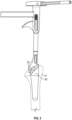
FIG. 4 is a front plan view of a humeral trial apparatus having a body and a thimble according to an example of the present application. -
FIG. 5 is a cross-sectional view of the humeral trial apparatus ofFIG. 4 mounted to one of the humeral stems ofFIG. 2 according to an example of the present application. -
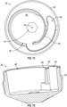
FIG. 6 is a perspective view of a bone facing side of the body of the humeral trial apparatus ofFIGS. 4 and5 . -
FIG. 7A is a perspective view of the thimble of the humeral trial apparatus ofFIGS. 4 and5 . -
FIG. 7B is a second perspective view of the thimble of the humeral trial apparatus ofFIGS. 4 and5 . -
FIG. 7C is a plan view of the thimble of the humeral trial apparatus ofFIGS. 4 and5 . -
FIG. 7D is a cross-sectional view of the thimble of the humeral trial apparatus ofFIGS. 4 and5 . -
FIG. 8 is a front plan view of a humeral trial apparatus having a body and a thimble according to another example of the present application. -
FIG. 9 is a perspective view of a bone facing side of the body of the humeral trial apparatus ofFIG. 8 . -
FIG. 10 is a perspective view of the thimble of the humeral trial apparatus ofFIG. 8 . -
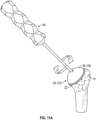
FIGS. 11A-11E show a method for positioning a prosthetic head component with a prosthetic stem relative to a bone using one of the humeral trial apparatuses described and illustrated herein. -
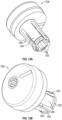
FIGS. 12A and 12B show perspective views of another example of a thimble of a humeral trial apparatus having a post as a connector. -
FIG. 1 is a perspective view of a totalshoulder arthroplasty system 10 comprising implanted a prosthetic glenoid 12 and an implanted humeralhead prosthetic system 14. The prosthetic glenoid 12 can include a glenoid 16 and humeralhead prosthetic system 14 can include ahumeral head 18. The glenoid 16 can be secured to scapula bone S using any suitable means, such as a center post and a plurality of peripheral posts. Thehumeral head 18 can be secured to humerus bone H via a stem adaptor 24 (FIGS. 7C and 7D ) that connects to thehumeral head 18 and to a humeral stem 30 (FIGS. 2 ,3 and5 ). - The scapula bone S and the humerus bone H are typically reamed, resected or otherwise prepared to receive the glenoid 16 and the
humeral stem 30. - As can be seen in
FIG. 1 , thehumeral head 18 can be mounted to humerus bone H such that theperimeter 20 ofhumeral head 18 can be substantially aligned withedge 22 of humerus bone H. It can be desirable for thehumeral head 18 to be properly centered on humerus bone H to achieve correct anatomic operation, for example, so that thehumeral head 18 can smoothly rotate against glenoid 16. As such, the position and size of thehumeral head 18 can be selected so that the diameter ofperimeter 20 substantially matches that ofedge 22. As described previously, it can be a complex process for thehumeral head 18 to be optimally aligned withedge 22 upon implantation. As such, the present disclosure provides a system, apparatus and method for trialing, positioning and aligning thehumeral head 18 with the humerus bone H. -
FIG. 2 is a schematic illustration of a plurality of the humeral stems 30 that can be used with the totalshoulder arthroplasty system 10. The humeral stems 30 are available in different sizes and lengths as necessary based upon patient factors such as bone size and bone quality. The humeral stems 30 can optionally include different stem lengths, can have portions coated or otherwise formed of porous material to facilitate bony ingrowth. Each of the humeral stems 30 can include aproximal end 32. - As shown in
FIG. 3 , theproximal end 32 can protrude slightly from or be flush with the glenoid surface of the humerus bone H when thehumeral stem 30 is positioned in the humerus bone H. Positioning of thehumeral stem 30 into a reamed recess in the humerus bone H can be performed by an inserter or guide as shown inFIG. 3 . - The
proximal end 32 of thehumeral stem 30 can include a trunnion 34 (FIG. 5 ), morse taper or other feature the facilitates connection of thehumeral stem 30 to the stein adaptor 24 (FIGS. 7C and 7D ), and hence, thehumeral head 18 as shown inFIG. 1 . -
FIG. 4 shows a plan view of a front (i.e. surgeon facing or non-bone facing) of ahumeral trial apparatus 35 according to an embodiment of the invention. Thehumeral trial apparatus 35 includes abody 36 and athimble 38. Thebody 36 and the thimble are moveably connected relative to one another via a joint 37. - The
body 36 can have a front surface 40 (sometimes referred to herein as a non-bone facing surface, proximal surface or top surface). Thebody 36 can be puck shaped, dome or hemispherical shaped according to some examples. Thefront surface 40 can terminate at aperimeter 41 of thebody 36. Thebody 36 can be circular in cross-section and can have a size and shape similar to that of the humeral head 18 (FIG. 1 ). - As shown in
FIG. 4 , thebody 36 can have arecess 42 forming an opening in thefront surface 40. This opening can provide access, via therecess 42, to a proximal end of thethimble 38 when thethimble 38 is inserted in and captured by thebody 36 as shown inFIG. 4 . The proximal end of thethimble 38 can have ahead 43, recess or other feature that can be engaged (via the recess 42) with a driver (shown inFIGS. 5 and7A ). The driver can engage or otherwise couple with thethimble 38 to rotate thethimble 38 relative to the body 36 (and/or the humeral stem) as further described herein. - According to the invention and as shown in
FIG. 4 , aportion 44 of thebody 36 that can include all or part of thebody 36 is transparent or translucent. This can facilitate the surgeon being able to view the position of thethimble 38, for example. Thebody 36 includes a plurality ofindicia 46. The plurality ofindicia 46 can be on one or more of thefront surface 40, can be within a recess of the body as further illustrated inFIG. 6 , and are on an opposing bone facing surface from thefront surface 40. The plurality ofindicia 46 can be circumferentially arranged along or adjacent theperimeter 41 and can be arranged circumferentially around a centerline axis A of thebody 36 as shown inFIG. 5 . -
FIG. 5 shows thehumeral trial apparatus 35, in particular thethimble 38, mounted to thetrunnion 34 of thehumeral stem 30. As shown inFIG. 5 , thethimble 38 is configured to rotate (via the joint 37) to adjust a position of thebody 36 relative to theprosthetic stem 30. To this end,FIG. 5 shows adriver 48 engaging thehead 43 of thethimble 38 to facilitate the rotation of thethimble 38 relative to thebody 36 and/or thehumeral stem 30. Put another way, thedriver 48 can rotate thethimble 38 relative to thebody 36 and can also be used to rotate thebody 36 andthimble 38 relative to thehumeral stem 30. -
FIGS. 5 and 6 illustrate a recess 50 (part of joint 37) within thebody 36. Thisrecess 50 can be configured (sized and shaped) to receive thethimble 38. Therecess 50 can have an opening on a distal surface 52 (also referred to herein as a bone interfacing surface or stem facing surface) of thebody 36 and can communicate with therecess 42 at a proximal portion. -
FIG. 5 shows the hemisphere shape of thebody 36 extending from theperimeter 41 to a domed peak that can be located at the centerline axis A of thebody 36. Therecess 42 can be located at the domed peak, can oppose therecess 50 and can communicate with therecess 50. InFIG. 5 , thethimble 38 is illustrated received in therecess 50 and can be rotatably captured by thebody 36 in a snap-fit engagement. As show inFIGS. 5 and 6 , a portion of therecess 50 can be formed by the one ormore fingers 54. - The snap-fit engagement can be facilitated by the one or
more fingers 54 of thebody 36. Thethimble 38 along theperimeter 41 can have a larger proximal diameter and then a smaller distal diameter. This change in diameter can form alip 56 on thethimble 38. Thelip 56 can have a chamfer of about 30 to 40 degrees between the larger diameter proximal portion and the smaller diameter distal portion. These fingers 54 (also illustrated inFIG. 6 ) can be figured to elastically deform slightly outward to receive thethimble 38. As shown inFIG. 5 , thefingers 54 can have chamfers, projections or other features configured to engage with mating features (e.g., a chamfer or lip 56) of thethimble 38 when thethimble 38 is fully inserted in therecess 50. Thelip 56 can be configured to be engaged by the one ormore fingers 54 when thethimble 38 is inserted in therecess 50. This engagement can retain thethimble 38 within thebody 36 but can allow thethimble 38 to be rotated relative to thebody 36, for example. -
FIG. 6 shows thebody 36 with thethimble 38 removed to better illustrate therecess 50 and the one ormore fingers 54. Thedistal surface 52 can be substantially flat and can include some or all of the plurality ofindicia 46, for example. As shown inFIG. 6 , some of the plurality ofindicia 46 can also be located within therecess 30. As shown inFIG. 6 , arecess 58 can be located outward (as measured from centerline axis A) of therecess 50 and the one ormore fingers 54. Thisrecess 58 can allow the one ormore fingers 50 to elastically flex outward as previously described to receive the thimble 38 (FIG. 4 ). -
FIGS. 7A-7D show thethimble 38 in further detail. Thethimble 38 can include thelip 56 along a periphery thereof and thehead 43 as previously described. Thethimble 38 can include aproximal surface 60 andindicia 62 as shown inFIG. 7A . Theproximal surface 60 can extend from a periphery of thethimble 38 to thehead 43, for example. Theindicia 62 can comprise a line or other marking on theproximal surface 62, for example. -
FIGS. 7B-7D show a distal side (also called a bone facing or stem facing side) of thethimble 38. Thethimble 38 includes adistal surface 64, arecess 66, one ormore fingers 68 and arecess 69. - As shown in
FIGS. 7B-7D , thedistal surface 64 can be substantially flat and can oppose theproximal surface 62. Therecess 66 can have an opening at thedistal surface 64. Therecess 66 can extend proximally from thedistal surface 64 to terminate adjacent or can communicate with thehead 43, as shown inFIGS. 7B and7C . Therecess 66 can be offset from a centerline axis AA (FIGS. 7B and7C ) and/or thehead 43 of thethimble 38. This offset can provide for adjustment of the position of thebody 36 relative to the humerus bone as previously discussed and further illustrated herein. - The
recess 66 can be partially formed by the one ormore fingers 68. The one ormore fingers 68 can be configured to elastically deflect outward towardrecess 69 when therecess 66 receives thetrunnion 34 of thehumeral stem 30. The one ormore fingers 68 can be configured to create a friction fit, snap-fit or other type of engagement with the trunnion 34 (FIG. 5 ) as desired. This engagement can allow thethimble 38 to rotatably mount to thetrunnion 34 as shown previously inFIG. 5 . Therecess 66 can be tapered in a manner to receive but also allow for removal of thethimble 38 from thetrunnion 34. -
FIGS. 8-10 show another example of ahumeral trial apparatus 135. Thehumeral trial apparatus 135 can be configured in the manner of thehumeral trial apparatus 35 previously described. Thus, thehumeral trial apparatus 135 includes abody 136 and athimble 138. Thebody 136 is comprised of a translucent or transparent material (e.g., polysulfone such as Radel® polyphenylsulfone (PPSU)) so as to be fully or partially see through for the surgeon. As shown inFIG. 9 , due to this translucent or transparent material a plurality ofindicia 146 are located on a distal surface 152 and/or arecess 150 of thebody 136 and can be visible through thebody 136 from a side opposing the distal surface 152. -
Thimble 138 can differ from thethimble 38 in that thehead 43 can be aslot 142, for example.Thimble 138 can be made of any suitable biocompatible material (e.g., metal, metal alloy such as titanium or titanium alloy, polymer, etc.).Thimble 138 need not be translucent or transparent, although the thimble can be translucent or transparent according to some examples. -
FIGS. 11A-11E show a method for positioning a prosthetic head component with a prosthetic stem relative to a bone. This method can be performed using one of the humeral trial apparatuses described and illustrated previously herein. -
FIG. 11A shows thedriver 48 being utilized with one of thehumeral trial apparatus FIG. 11A , thedriver 48 can be rotated to rotate the thimble relative to thebody body body thimble body edge 22 of the humerus bone H as shown inFIG. 11B . -
FIG. 11B shows the surgeon can start with theindicia 62 of thethimble indicia thimble FIG. 11A to match theedge 22 of the humerus bone H. This can change the relative positions of thebody thimble thimble FIG. 11B . Optionally, an amount of maximum offset from theedge 22 can be determined and noted if desired. Once the desired position for thebody indicia 62 of thethimble FIG. 11B ) to theedge 22 and the bone (such as the edge 22) can be marked with amark 199 as illustrated inFIG. 11B using known methods. - As shown in
FIG. 11C , thehumeral head 18 can be placed in into an impactor tray. Thestem adapter 24 can have abody 200 configured to engage thehumeral head 18. Thestem adaptor 24 can have aneck 202 configured to engage the humeral stem 30 (FIGS. 2 ,3 and5 ). - In
FIGS. 11C and11D , thestem adaptor 24 can be selected and can have anindicia 204 thereon. Theindicia 204 can be configured in a similar or identical manner to theindicia 62 of thethimble humeral head 18 can have a plurality ofindicia 206. Theindicia 204 can be used with the plurality ofindicia 206 as shown inFIGS. 11C and11D . The plurality ofindicia 206 can be configured in a same or similar manner to theindicia body indicia 206 can be identical to (i.e. each can be circumferentially arranged about a centerline axis of thehumeral head 18, can be identically spaced and positioned, etc.) to theindicia body body indicia indicia 206 of thehumeral head 18. Thus, a relative position between thestem adaptor 24 and thehumeral head 18 can be determined by replicating with theindicia 204 of thestem adaptor 24 and the plurality ofindicia 206 of thehumeral head 18, the relative positions of thethimble body indicia 62 of thethimble indicia body - As shown in
FIG. 11D , theindicia 204 can be extrapolated linearly outward (as indicated with dashed line) to aperiphery 208 of thehumeral head 18. Amark 210 can be made on the periphery in this location. InFIG. 11E , thehumeral head 18 and the stem adaptor (not shown) can be adjusted to align themark 210 with the mark 199 (FIG. 11B ). Thus, the position of the stem adaptor and the humeral head on the humeral stem can be positioned to replicate the position of the body and thimble on the humeral stem. - Thus, the method of
FIGS. 11A-11E can position thehumeral head 18 with theprosthetic stem 30 relative to the humerus bone H. The method can include mounting the prosthetic stem to the bone, inserting the thimble within the body, mounting the thimble on the prosthetic stem, adjusting a relative position between the body and the thimble, marking the bone, recreating the relative position with a stem adaptor and the prosthetic head component; marking the prosthetic head component with the aid of an indicia on the stem adaptor once the recreating the relative position with the stem adaptor and the prosthetic head component is achieved, aligning the marking on the bone with the marking on the prosthetic head component, and attaching the prosthetic head component to the prosthetic stem via the stem adaptor. -
FIGS. 12A and 12B show athimble 238 according to another example. Thethimble 238 can differ from thethimble recess 66 can be replaced by a male feature such as astem 200 having one or moreflexible fingers 202 that definesidewalls 204 thereof Thestem 200 via the one or moreflexible fingers 202, which can be separated by slots, can be configured to couple with the proximal head of the prosthetic stem in an adjustable manner as previously discussed. It is further recognized that according to further embodiments the body can include a male feature facilitating adjustable connection with the thimble, for example. - The above detailed description includes references to the accompanying drawings, which form a part of the detailed description. The drawings show, by way of illustration, specific embodiments in which the invention can be practiced. These embodiments are also referred to herein as "examples." Such examples can include elements in addition to those shown or described. However, the present inventors also contemplate examples in which only those elements shown or described are provided. Moreover, the present inventors also contemplate examples using any combination or permutation of those elements shown or described (or one or more aspects thereof), either with respect to a particular example (or one or more aspects thereof), or with respect to other examples (or one or more aspects thereof) shown or described herein.
- In this document, the terms "a" or "an" are used, as is common in patent documents, to include one or more than one, independent of any other instances or usages of "at least one" or "one or more." In this document, the term "or" is used to refer to a nonexclusive or, such that "A or B" includes "A but not B," "B but not A," and "A and B," unless otherwise indiciated. In this document, the terms "including" and "in which" are used as the plain-English equivalents of the respective terms "comprising" and "wherein." Also, in the following claims, the terms "including" and "comprising" are open-ended, that is, a system, device, article, composition, formulation, or process that includes elements in addition to those listed after such a term in a claim are still deemed to fall within the scope of that claim. Moreover, in the following claims, the terms "first," "second," and "third," etc. are used merely as labels, and are not intended to impose numerical requirements on their objects.
- The above description is intended to be illustrative, and not restrictive. For example, the above-described examples (or one or more aspects thereof) may be used in combination with each other. Other embodiments can be used, such as by one of ordinary skill in the art upon reviewing the above description. The Abstract is provided to allow the reader to quickly ascertain the nature of the technical disclosure. It is submitted with the understanding that it will not be used to interpret or limit the scope or meaning of the claims. Also, in the above Detailed Description, various features may be grouped together to streamline the disclosure. This should not be interpreted as intending that an unclaimed disclosed feature is essential to any claim. Rather, inventive subject matter may lie in less than all features of a particular disclosed embodiment. Thus, the following claims are hereby incorporated into the Detailed Description as examples or embodiments, with each claim standing on its own as a separate embodiment, and it is contemplated that such embodiments can be combined with each other in various combinations or permutations. The scope of the invention is defined by the appended claims.
Claims (9)
- A trial apparatus (35) for selecting a position of a prosthetic head component on a humerus, the trial apparatus (35) comprising:a body (36) having a plurality of indicia (46), wherein the body forms a portion of a joint (37);a thimble (38) couplable to the body (36) via the joint (37), wherein the thimble is rotatable relative to the body (36) via the joint (37) and includes one or more indicia (62) for use with the plurality of indicia (46) of the body (36), and wherein the thimble is mountable to a prosthetic stem (30) implanted in the humerus,wherein the plurality of indicia (46) are on a distal surface of the body (36), characterised in that the body (36) is translucent such that the plurality of indicia (46) are visible through the body (36) from a side opposing the distal surface.
- The trial apparatus (35) of claim 1, wherein the plurality of indicia (46) are arranged circumferentially about a centerline axis of the body (36).
- The trial apparatus (35) of any one of claims 1-2, wherein the body (36) comprises a hemisphere.
- The trial apparatus (35) of any one of claims 1-3, wherein body (36) defines a recess (50) that comprises the portion of the joint (37), wherein the thimble (38) is receivable by the recess, wherein the recess is formed by one or more fingers (54), and wherein the fingers (54) are configured to elastically deform to retain the thimble (38) in a snap-fit engagement.
- The trial apparatus (35) of claim 4, wherein the thimble (38) has a lip (56) configured to be engaged by the one or more fingers (54) when the thimble (38) is inserted in the recess.
- The trial apparatus (35) of any one of claims 1-5, wherein the body (36) includes a second recess (42) opposing the joint (37), wherein the second recess communicates with the joint (37).
- The trial apparatus (35) of claim 6, wherein the thimble (38) includes a head (43) on a proximal end thereof, wherein, when the body (36) and the thimble (38) are assembled via the joint (37), the head (43) is accessible through the second recess of the body (36).
- The trial apparatus (35) of any one claims 1-7, wherein the thimble (38) includes one of a recess (66) or a stem, and wherein a finger (68) forms at least a portion of the recess (66) or stem, and wherein the recess (66) or stem of the thimble (38) is configured to elastically deform to retain the thimble (38) on the prosthetic stem (30).
- The trial apparatus (35) of any one of claims 1-8, wherein the thimble (38) is rotatable relative to the body (36) to adjust a position of the body (36) relative to the prosthetic stem (30).
Applications Claiming Priority (2)
| Application Number | Priority Date | Filing Date | Title |
|---|---|---|---|
| US202063121018P | 2020-12-03 | 2020-12-03 | |
| PCT/US2021/061625 WO2022120060A1 (en) | 2020-12-03 | 2021-12-02 | Methods and apparatuses for trialing a humeral head |
Publications (2)
| Publication Number | Publication Date |
|---|---|
| EP4255354A1 EP4255354A1 (en) | 2023-10-11 |
| EP4255354B1 true EP4255354B1 (en) | 2025-03-26 |
Family
ID=79731113
Family Applications (1)
| Application Number | Title | Priority Date | Filing Date |
|---|---|---|---|
| EP21845130.0A Active EP4255354B1 (en) | 2020-12-03 | 2021-12-02 | Apparatuses for trialing a humeral head |
Country Status (4)
| Country | Link |
|---|---|
| US (1) | US20230310166A1 (en) |
| EP (1) | EP4255354B1 (en) |
| CN (1) | CN116456939A (en) |
| WO (1) | WO2022120060A1 (en) |
Family Cites Families (11)
| Publication number | Priority date | Publication date | Assignee | Title |
|---|---|---|---|---|
| US6673114B2 (en) | 2000-05-03 | 2004-01-06 | Smith & Nephew, Inc. | Multi modular trialing system and instrumentation |
| US20020016634A1 (en) | 2000-07-28 | 2002-02-07 | Brian Maroney | Device and method for positioning an eccentric humeral head of a humerus prothesis for a shoulder arthroplasty |
| US6736852B2 (en) | 2001-02-27 | 2004-05-18 | Incumed, Inc. | Adjustable bone prostheses and related methods |
| US8052758B1 (en) | 2005-03-09 | 2011-11-08 | Biomet Manufacturing Corp. | Method and apparatus for trialing a modular humeral head |
| KR20080002824A (en) * | 2005-03-29 | 2008-01-04 | 신세스 게엠바하 | Implantation method and apparatus for hydrogel hydrogel prosthesis |
| GB0803723D0 (en) * | 2008-02-29 | 2008-04-09 | Depuy Int Ltd | An instrument for use in a joint replacement procedure |
| EP2846741B8 (en) * | 2012-05-07 | 2018-10-24 | Smith&Nephew, Inc. | Compaction pliers having removable cutting inserts |
| US8906102B2 (en) * | 2012-05-31 | 2014-12-09 | Howmedica Osteonics Corp. | Lateral entry insert for cup trial |
| US10226349B2 (en) | 2013-03-08 | 2019-03-12 | Mayo Foundation For Medical Education And Research | Shoulder prosthesis with variable inclination humeral head component |
| CN204931906U (en) * | 2015-08-18 | 2016-01-06 | 上海市杨浦区中心医院 | A kind of visual tibial prosthesis measuring device |
| CA3113978C (en) * | 2018-10-02 | 2023-10-24 | Tornier, Inc. | Modular humeral head |
-
2021
- 2021-12-02 EP EP21845130.0A patent/EP4255354B1/en active Active
- 2021-12-02 WO PCT/US2021/061625 patent/WO2022120060A1/en not_active Ceased
- 2021-12-02 CN CN202180076998.1A patent/CN116456939A/en active Pending
- 2021-12-02 US US18/038,614 patent/US20230310166A1/en active Pending
Also Published As
| Publication number | Publication date |
|---|---|
| EP4255354A1 (en) | 2023-10-11 |
| US20230310166A1 (en) | 2023-10-05 |
| WO2022120060A1 (en) | 2022-06-09 |
| CN116456939A (en) | 2023-07-18 |
Similar Documents
| Publication | Publication Date | Title |
|---|---|---|
| US6673114B2 (en) | Multi modular trialing system and instrumentation | |
| US6126694A (en) | Universal distal broach and stem trial | |
| US9326862B2 (en) | Variable prosthesis | |
| US6117138A (en) | Instruments for forming bony cavity for implantable femoral, hip prosthesis | |
| AU2008229883B2 (en) | Expandable reverse shoulder trial | |
| CA2903390C (en) | Shoulder prosthesis with variable inclination humeral head component | |
| US8795379B2 (en) | Variable prosthesis | |
| US20180092760A1 (en) | Shoulder Prosthesis With Variable Inclination Humeral Head Component | |
| US12076249B2 (en) | Methods and apparatuses for trialing a humeral head | |
| WO2003005933A2 (en) | Shoulder prosthesis | |
| CA2981745A1 (en) | Convertible glenoid | |
| AU2019391414B2 (en) | Trialling | |
| US12186196B2 (en) | Elbow arthroplasty apparatus, system, and method | |
| US20230093485A1 (en) | Offset adapters, trial implant systems, and implant systems allowing for selectable eccentricity | |
| CA3046366A1 (en) | Shoulder prosthesis with variable inclination, offset, and version of humeral component | |
| US11490907B2 (en) | Instruments and systems for an orthopedic shoulder replacement | |
| US20230310166A1 (en) | Methods and apparatuses for trialing a humeral head | |
| US20170020677A1 (en) | Shoulder Arthroplasty System With Combination Humeral Sizer, Trial, And Guide | |
| AU2023323671A1 (en) | Anatomically shaped stemless shoulder prosthesis for total shoulder replacement and reverse total shoulder replacement |
Legal Events
| Date | Code | Title | Description |
|---|---|---|---|
| STAA | Information on the status of an ep patent application or granted ep patent |
Free format text: STATUS: UNKNOWN |
|
| STAA | Information on the status of an ep patent application or granted ep patent |
Free format text: STATUS: THE INTERNATIONAL PUBLICATION HAS BEEN MADE |
|
| PUAI | Public reference made under article 153(3) epc to a published international application that has entered the european phase |
Free format text: ORIGINAL CODE: 0009012 |
|
| STAA | Information on the status of an ep patent application or granted ep patent |
Free format text: STATUS: REQUEST FOR EXAMINATION WAS MADE |
|
| 17P | Request for examination filed |
Effective date: 20230703 |
|
| AK | Designated contracting states |
Kind code of ref document: A1 Designated state(s): AL AT BE BG CH CY CZ DE DK EE ES FI FR GB GR HR HU IE IS IT LI LT LU LV MC MK MT NL NO PL PT RO RS SE SI SK SM TR |
|
| DAV | Request for validation of the european patent (deleted) | ||
| DAX | Request for extension of the european patent (deleted) | ||
| GRAP | Despatch of communication of intention to grant a patent |
Free format text: ORIGINAL CODE: EPIDOSNIGR1 |
|
| STAA | Information on the status of an ep patent application or granted ep patent |
Free format text: STATUS: GRANT OF PATENT IS INTENDED |
|
| INTG | Intention to grant announced |
Effective date: 20241104 |
|
| GRAS | Grant fee paid |
Free format text: ORIGINAL CODE: EPIDOSNIGR3 |
|
| GRAA | (expected) grant |
Free format text: ORIGINAL CODE: 0009210 |
|
| STAA | Information on the status of an ep patent application or granted ep patent |
Free format text: STATUS: THE PATENT HAS BEEN GRANTED |
|
| AK | Designated contracting states |
Kind code of ref document: B1 Designated state(s): AL AT BE BG CH CY CZ DE DK EE ES FI FR GB GR HR HU IE IS IT LI LT LU LV MC MK MT NL NO PL PT RO RS SE SI SK SM TR |
|
| P01 | Opt-out of the competence of the unified patent court (upc) registered |
Free format text: CASE NUMBER: APP_7562/2025 Effective date: 20250213 |
|
| REG | Reference to a national code |
Ref country code: GB Ref legal event code: FG4D |
|
| REG | Reference to a national code |
Ref country code: CH Ref legal event code: EP |
|
| REG | Reference to a national code |
Ref country code: DE Ref legal event code: R096 Ref document number: 602021028275 Country of ref document: DE |
|
| REG | Reference to a national code |
Ref country code: IE Ref legal event code: FG4D |
|
| PG25 | Lapsed in a contracting state [announced via postgrant information from national office to epo] |
Ref country code: RS Free format text: LAPSE BECAUSE OF FAILURE TO SUBMIT A TRANSLATION OF THE DESCRIPTION OR TO PAY THE FEE WITHIN THE PRESCRIBED TIME-LIMIT Effective date: 20250626 |
|
| PG25 | Lapsed in a contracting state [announced via postgrant information from national office to epo] |
Ref country code: FI Free format text: LAPSE BECAUSE OF FAILURE TO SUBMIT A TRANSLATION OF THE DESCRIPTION OR TO PAY THE FEE WITHIN THE PRESCRIBED TIME-LIMIT Effective date: 20250326 |
|
| REG | Reference to a national code |
Ref country code: LT Ref legal event code: MG9D |
|
| PG25 | Lapsed in a contracting state [announced via postgrant information from national office to epo] |
Ref country code: NO Free format text: LAPSE BECAUSE OF FAILURE TO SUBMIT A TRANSLATION OF THE DESCRIPTION OR TO PAY THE FEE WITHIN THE PRESCRIBED TIME-LIMIT Effective date: 20250626 |
|
| PG25 | Lapsed in a contracting state [announced via postgrant information from national office to epo] |
Ref country code: HR Free format text: LAPSE BECAUSE OF FAILURE TO SUBMIT A TRANSLATION OF THE DESCRIPTION OR TO PAY THE FEE WITHIN THE PRESCRIBED TIME-LIMIT Effective date: 20250326 |
|
| PG25 | Lapsed in a contracting state [announced via postgrant information from national office to epo] |
Ref country code: LV Free format text: LAPSE BECAUSE OF FAILURE TO SUBMIT A TRANSLATION OF THE DESCRIPTION OR TO PAY THE FEE WITHIN THE PRESCRIBED TIME-LIMIT Effective date: 20250326 |
|
| PG25 | Lapsed in a contracting state [announced via postgrant information from national office to epo] |
Ref country code: GR Free format text: LAPSE BECAUSE OF FAILURE TO SUBMIT A TRANSLATION OF THE DESCRIPTION OR TO PAY THE FEE WITHIN THE PRESCRIBED TIME-LIMIT Effective date: 20250627 Ref country code: BG Free format text: LAPSE BECAUSE OF FAILURE TO SUBMIT A TRANSLATION OF THE DESCRIPTION OR TO PAY THE FEE WITHIN THE PRESCRIBED TIME-LIMIT Effective date: 20250326 |
|
| REG | Reference to a national code |
Ref country code: NL Ref legal event code: MP Effective date: 20250326 |
|
| PG25 | Lapsed in a contracting state [announced via postgrant information from national office to epo] |
Ref country code: NL Free format text: LAPSE BECAUSE OF FAILURE TO SUBMIT A TRANSLATION OF THE DESCRIPTION OR TO PAY THE FEE WITHIN THE PRESCRIBED TIME-LIMIT Effective date: 20250326 |
|
| PG25 | Lapsed in a contracting state [announced via postgrant information from national office to epo] |
Ref country code: SE Free format text: LAPSE BECAUSE OF FAILURE TO SUBMIT A TRANSLATION OF THE DESCRIPTION OR TO PAY THE FEE WITHIN THE PRESCRIBED TIME-LIMIT Effective date: 20250326 |
|
| REG | Reference to a national code |
Ref country code: AT Ref legal event code: MK05 Ref document number: 1778313 Country of ref document: AT Kind code of ref document: T Effective date: 20250326 |
|
| PG25 | Lapsed in a contracting state [announced via postgrant information from national office to epo] |
Ref country code: SM Free format text: LAPSE BECAUSE OF FAILURE TO SUBMIT A TRANSLATION OF THE DESCRIPTION OR TO PAY THE FEE WITHIN THE PRESCRIBED TIME-LIMIT Effective date: 20250326 |
|
| PG25 | Lapsed in a contracting state [announced via postgrant information from national office to epo] |
Ref country code: PT Free format text: LAPSE BECAUSE OF FAILURE TO SUBMIT A TRANSLATION OF THE DESCRIPTION OR TO PAY THE FEE WITHIN THE PRESCRIBED TIME-LIMIT Effective date: 20250728 Ref country code: ES Free format text: LAPSE BECAUSE OF FAILURE TO SUBMIT A TRANSLATION OF THE DESCRIPTION OR TO PAY THE FEE WITHIN THE PRESCRIBED TIME-LIMIT Effective date: 20250326 |
|
| PG25 | Lapsed in a contracting state [announced via postgrant information from national office to epo] |
Ref country code: IT Free format text: LAPSE BECAUSE OF FAILURE TO SUBMIT A TRANSLATION OF THE DESCRIPTION OR TO PAY THE FEE WITHIN THE PRESCRIBED TIME-LIMIT Effective date: 20250326 Ref country code: PL Free format text: LAPSE BECAUSE OF FAILURE TO SUBMIT A TRANSLATION OF THE DESCRIPTION OR TO PAY THE FEE WITHIN THE PRESCRIBED TIME-LIMIT Effective date: 20250326 |
|
| PG25 | Lapsed in a contracting state [announced via postgrant information from national office to epo] |
Ref country code: AT Free format text: LAPSE BECAUSE OF FAILURE TO SUBMIT A TRANSLATION OF THE DESCRIPTION OR TO PAY THE FEE WITHIN THE PRESCRIBED TIME-LIMIT Effective date: 20250326 |
|
| PG25 | Lapsed in a contracting state [announced via postgrant information from national office to epo] |
Ref country code: EE Free format text: LAPSE BECAUSE OF FAILURE TO SUBMIT A TRANSLATION OF THE DESCRIPTION OR TO PAY THE FEE WITHIN THE PRESCRIBED TIME-LIMIT Effective date: 20250326 |
|
| PG25 | Lapsed in a contracting state [announced via postgrant information from national office to epo] |
Ref country code: RO Free format text: LAPSE BECAUSE OF FAILURE TO SUBMIT A TRANSLATION OF THE DESCRIPTION OR TO PAY THE FEE WITHIN THE PRESCRIBED TIME-LIMIT Effective date: 20250326 |
|
| PG25 | Lapsed in a contracting state [announced via postgrant information from national office to epo] |
Ref country code: SK Free format text: LAPSE BECAUSE OF FAILURE TO SUBMIT A TRANSLATION OF THE DESCRIPTION OR TO PAY THE FEE WITHIN THE PRESCRIBED TIME-LIMIT Effective date: 20250326 |
|
| PG25 | Lapsed in a contracting state [announced via postgrant information from national office to epo] |
Ref country code: IS Free format text: LAPSE BECAUSE OF FAILURE TO SUBMIT A TRANSLATION OF THE DESCRIPTION OR TO PAY THE FEE WITHIN THE PRESCRIBED TIME-LIMIT Effective date: 20250726 |
|
| REG | Reference to a national code |
Ref country code: CH Ref legal event code: U11 Free format text: ST27 STATUS EVENT CODE: U-0-0-U10-U11 (AS PROVIDED BY THE NATIONAL OFFICE) Effective date: 20260101 |
|
| REG | Reference to a national code |
Ref country code: DE Ref legal event code: R097 Ref document number: 602021028275 Country of ref document: DE |
|
| PGFP | Annual fee paid to national office [announced via postgrant information from national office to epo] |
Ref country code: DE Payment date: 20251112 Year of fee payment: 5 |
|
| PGFP | Annual fee paid to national office [announced via postgrant information from national office to epo] |
Ref country code: GB Payment date: 20251114 Year of fee payment: 5 |
|
| PG25 | Lapsed in a contracting state [announced via postgrant information from national office to epo] |
Ref country code: DK Free format text: LAPSE BECAUSE OF FAILURE TO SUBMIT A TRANSLATION OF THE DESCRIPTION OR TO PAY THE FEE WITHIN THE PRESCRIBED TIME-LIMIT Effective date: 20250326 |
|
| PGFP | Annual fee paid to national office [announced via postgrant information from national office to epo] |
Ref country code: FR Payment date: 20251112 Year of fee payment: 5 |
|
| PG25 | Lapsed in a contracting state [announced via postgrant information from national office to epo] |
Ref country code: CZ Free format text: LAPSE BECAUSE OF FAILURE TO SUBMIT A TRANSLATION OF THE DESCRIPTION OR TO PAY THE FEE WITHIN THE PRESCRIBED TIME-LIMIT Effective date: 20250326 |
|
| PLBE | No opposition filed within time limit |
Free format text: ORIGINAL CODE: 0009261 |
|
| STAA | Information on the status of an ep patent application or granted ep patent |
Free format text: STATUS: NO OPPOSITION FILED WITHIN TIME LIMIT |
|
| REG | Reference to a national code |
Ref country code: CH Ref legal event code: L10 Free format text: ST27 STATUS EVENT CODE: U-0-0-L10-L00 (AS PROVIDED BY THE NATIONAL OFFICE) Effective date: 20260211 |
|
| 26N | No opposition filed |
Effective date: 20260105 |
|
| PGFP | Annual fee paid to national office [announced via postgrant information from national office to epo] |
Ref country code: CH Payment date: 20260101 Year of fee payment: 5 |