EP4255118A1 - System and method for color sensor characterization, calibration, and threshold-setting - Google Patents
System and method for color sensor characterization, calibration, and threshold-setting Download PDFInfo
- Publication number
- EP4255118A1 EP4255118A1 EP23165110.0A EP23165110A EP4255118A1 EP 4255118 A1 EP4255118 A1 EP 4255118A1 EP 23165110 A EP23165110 A EP 23165110A EP 4255118 A1 EP4255118 A1 EP 4255118A1
- Authority
- EP
- European Patent Office
- Prior art keywords
- color
- color space
- led
- calibration
- scaled
- Prior art date
- Legal status (The legal status is an assumption and is not a legal conclusion. Google has not performed a legal analysis and makes no representation as to the accuracy of the status listed.)
- Granted
Links
Images



Classifications
-
- G—PHYSICS
- G01—MEASURING; TESTING
- G01J—MEASUREMENT OF INTENSITY, VELOCITY, SPECTRAL CONTENT, POLARISATION, PHASE OR PULSE CHARACTERISTICS OF INFRARED, VISIBLE OR ULTRAVIOLET LIGHT; COLORIMETRY; RADIATION PYROMETRY
- G01J3/00—Spectrometry; Spectrophotometry; Monochromators; Measuring colours
- G01J3/02—Details
- G01J3/0297—Constructional arrangements for removing other types of optical noise or for performing calibration
-
- H—ELECTRICITY
- H05—ELECTRIC TECHNIQUES NOT OTHERWISE PROVIDED FOR
- H05B—ELECTRIC HEATING; ELECTRIC LIGHT SOURCES NOT OTHERWISE PROVIDED FOR; CIRCUIT ARRANGEMENTS FOR ELECTRIC LIGHT SOURCES, IN GENERAL
- H05B45/00—Circuit arrangements for operating light-emitting diodes [LED]
- H05B45/20—Controlling the colour of the light
- H05B45/22—Controlling the colour of the light using optical feedback
-
- G—PHYSICS
- G01—MEASURING; TESTING
- G01J—MEASUREMENT OF INTENSITY, VELOCITY, SPECTRAL CONTENT, POLARISATION, PHASE OR PULSE CHARACTERISTICS OF INFRARED, VISIBLE OR ULTRAVIOLET LIGHT; COLORIMETRY; RADIATION PYROMETRY
- G01J3/00—Spectrometry; Spectrophotometry; Monochromators; Measuring colours
- G01J3/46—Measurement of colour; Colour measuring devices, e.g. colorimeters
- G01J3/462—Computing operations in or between colour spaces; Colour management systems
-
- G—PHYSICS
- G01—MEASURING; TESTING
- G01J—MEASUREMENT OF INTENSITY, VELOCITY, SPECTRAL CONTENT, POLARISATION, PHASE OR PULSE CHARACTERISTICS OF INFRARED, VISIBLE OR ULTRAVIOLET LIGHT; COLORIMETRY; RADIATION PYROMETRY
- G01J3/00—Spectrometry; Spectrophotometry; Monochromators; Measuring colours
- G01J3/46—Measurement of colour; Colour measuring devices, e.g. colorimeters
- G01J3/50—Measurement of colour; Colour measuring devices, e.g. colorimeters using electric radiation detectors
- G01J3/501—Colorimeters using spectrally-selective light sources, e.g. LEDs
-
- G—PHYSICS
- G01—MEASURING; TESTING
- G01J—MEASUREMENT OF INTENSITY, VELOCITY, SPECTRAL CONTENT, POLARISATION, PHASE OR PULSE CHARACTERISTICS OF INFRARED, VISIBLE OR ULTRAVIOLET LIGHT; COLORIMETRY; RADIATION PYROMETRY
- G01J3/00—Spectrometry; Spectrophotometry; Monochromators; Measuring colours
- G01J3/46—Measurement of colour; Colour measuring devices, e.g. colorimeters
- G01J3/50—Measurement of colour; Colour measuring devices, e.g. colorimeters using electric radiation detectors
- G01J3/505—Measurement of colour; Colour measuring devices, e.g. colorimeters using electric radiation detectors measuring the colour produced by lighting fixtures other than screens, monitors, displays or CRTs
-
- G—PHYSICS
- G01—MEASURING; TESTING
- G01J—MEASUREMENT OF INTENSITY, VELOCITY, SPECTRAL CONTENT, POLARISATION, PHASE OR PULSE CHARACTERISTICS OF INFRARED, VISIBLE OR ULTRAVIOLET LIGHT; COLORIMETRY; RADIATION PYROMETRY
- G01J3/00—Spectrometry; Spectrophotometry; Monochromators; Measuring colours
- G01J3/46—Measurement of colour; Colour measuring devices, e.g. colorimeters
- G01J3/52—Measurement of colour; Colour measuring devices, e.g. colorimeters using colour charts
- G01J3/524—Calibration of colorimeters
Definitions
- Surgical robotic systems are currently being used in a variety of surgical procedures, including minimally invasive medical procedures.
- Some surgical robotic systems include a surgeon console controlling a surgical robotic arm and a surgical instrument having an end effector (e.g., forceps or grasping instrument) coupled to and actuated by the robotic arm.
- the robotic arm In operation, the robotic arm is moved to a position over a patient and then guides the surgical instrument into a small incision via a surgical port or a natural orifice of a patient to position the end effector at a work site within the patient's body.
- the surgeon console interacts with a robotic system to conduct the surgery.
- the surgeon console has a display displaying images of the surgical field captured by an endoscopic camera, input devices transferring motions made by the surgeon to the end effectors within the surgical field, and foot pedals configured to receive commands from the surgeon to activate devices and perform other functions of the surgical robotic arms.
- Multiple foot pedals may be used, which are labeled for their specific functions.
- foot pedals are illuminated with light emitting diode (LED) lights.
- the LED lights generate different colors allowing the surgeon to differentiate between foot pedals.
- the present disclosure relates to improved systems and methods to systematically characterize the light sensor of the foot pedals and calibrate the readings from the light sensor in order to increase the manufacturing yield of the LEDs and components that utilize the LEDs.
- LEDs may be used in a surgical robotic system to generate different colors to distinguish different buttons or pedals. Foot pedals in a surgeon console are illuminated to provide better visibility. The foot pedals are used to activate energy delivery for monopolar or bipolar instruments, switch active robotic arms, or activate any other suitable function. The surgical robotic systems according to the present disclosure confirm the foot pedals are correctly illuminated.
- the foot pedal includes a color sensor disposed on a printed circuit board (PCB) along with the LEDs.
- the color sensor is configured to detect red, green and blue (R, G, B) lights in different channels. Some sensors may have multiple channels to detect all the lights together, i.e., as a white channel. The readings from the color sensor are expressed in RGB color space.
- RGB color space Since it is relatively hard to do color classification directly in the RGB color space, such readings are converted to hue-saturation-value (HSV) color space. After such conversion, the color classification may be simplified to a two-dimension problem in HSV space. Simple thresholds may then be used for hue and saturation for the purpose of classification of colors.
- HSV hue-saturation-value
- the bandwidth of the light generated by individual LEDs is quite narrow, e.g., around 20 nm to 30 nm
- the readings from the color sensor usually have significant components from other channels. Averaging the readings over multiple samples fails to reduce the amplitude of readings from other interfering channels. Due to this significant cross talk between different color channels in the color sensor, it is difficult to classify the color from these readings. In addition, there is significant spread between different color sensors from the same batch, and even more so between sensors of different batches.
- thresholds In order to classify the colors from the readings, proper thresholds need to be set. Due to the cross talk between different channels and spreads between different sensors, the thresholds can work only for some sensors, which in turn can cause the manufacturing yield of the LEDs to drop significantly. To improve the manufacturing yield, there is a need to accurately characterize the color sensors. In addition, a calibration and filtering process may also be used to reduce the cross talk in the system. With proper calibration, the classification accuracy and manufacturing yield is improved significantly.
- the present disclosure provides a system and method to confirm that a correct color signal is generated using a color sensor, which detects the light generated by the LED.
- the readings from the color sensor are calculated for color classification and confirmation by the system.
- the system and method are configured to characterize the color sensors from different batches and generate a calibration matrix based on linear system theory. With this approach, the readings from the color sensor are first corrected by the calibration matrix, which reduces the systematic errors within the system. After correction, the readings are converted to another color space and are classified into corresponding colors. Based on the characterization data, a Monte Carlo simulation is performed to find proper thresholds for color classification.
- the presently disclosed system and method improve the yield of the LEDs and the products that used them, e.g., foot pedals, as well as classification accuracy of colors.
- a method for generating a calibration matrix includes driving a red LED only with (128, 0, 0), by setting the driving signal of the red LED to the middle level, the green LED to zero, the blue LED to zero, and obtaining and scaling readings against the red channel as [1, Gr / Rr, Br / Rr, Wr ].
- the method also includes driving green LED only with (0, 128, 0) by setting the driving signal of the red LED to zero, the green LED to the middle level, the blue LED to zero, and obtaining and scaling against the green channel as [ Rg / Gg, 1, Bg / Gg , Wg ].
- the method further includes driving the blue LED only with (0, 0, 128) by setting the driving signal of the red LED to zero, the green LED to zero, the blue LED to middle level, and obtaining and scaling against the blue channel as [ Rb / Bb , Gb / Bb , 1, Wb ].
- the method also includes repeating the above steps for each of a plurality of different foot pedals for N times to obtain N samples of [1, Gr / Rr, Br / Rr, Wr ], [ Rg / Gg , 1, BglGg , Wg ], and [ Rb / Bb , Gb / Bb , 1, Wb ].
- the method further includes calculating the mean and standard deviation of these samples and uses the average of the scaled readings to calculate the calibration matrix for these foot pedals.
- the calibration matrix may be calculated directly from the data, i.e., without calculating the mean.
- the unscaled readings may be collected as [ Rr , Gr, Br, Wr ], [ Rg , Gg , Bg , Wg ], and [ Rb , Gb , Bb , Wb ].
- the method may further include calculating average and standard deviation of these unscaled readings.
- the method further includes simulating additional colors based on linear theory. Monte Carlo simulation may be used to generate large samples of simulated foot pedals. The data from the simulation may also be used to set proper thresholds for color classification.
- a method for determining color classification based on the calibration matrix includes driving an LED to the intended color and obtain readings as [R, G, B, W].
- the method further includes applying H*, S* and W thresholds for color classification.
- a method for generating a calibration parameter for light sources includes activating at least one LED of a plurality of multicolor LEDs of a light source and measuring a color of the at least one LED in a first color space.
- the method also includes scaling the color of at least one LED relative to the plurality of multicolor LEDs, obtaining a plurality of scaled color measurements, and calculating a calibration matrix based on the plurality of scaled color measurements.
- the first color space may be a red, green, or blue (RGB) color space and the calibration matrix may be a 3x3 matrix of adjustment values.
- the method may also include calculating a mean of the plurality of scaled color measurements.
- the method may further include calculating a standard deviation of the plurality of scaled color measurements. Calculating the calibration matrix may be based on the mean and standard deviation of the plurality of scaled color measurements.
- the method may additionally include simulating a plurality of simulated color measurements using a Monte Carlo simulation.
- the method may also include generating a plurality of calibration thresholds in a second color space.
- the second color space may be a hue, saturation, value (HSV) color space.
- a method for calibrating a light source includes activating at least one LED of a plurality of multicolor LEDs of a light source and measuring a color of the at least one LED in a first color space.
- the method further includes converting the measured color using a calibration matrix to a calibrated first color space measurement and then converting the calibrated first color space measurement to second color space values.
- the method additionally includes comparing the second color space values to thresholds derived from the calibration matrix and outputting a calibration failure message in response to the second color space values exceeding the thresholds.
- Implementations of the above embodiment may include one or more of the following features.
- the first color space may be a red, green, blue (RGB) color space.
- the second color space may be a hue, saturation, value (HSV) color space.
- the calibration matrix may be a 3 ⁇ 3 matrix of adjustment values.
- the plurality of multicolor LEDs may be disposed in a foot pedal of a surgeon console for a surgical robotic system.
- a computer-readable medium includes instructions executable by a processor that are configured to cause a computing system to perform a method which includes activating at least one LED of a plurality of multicolor LEDs of a light source. The method also includes measuring the color of at least one LED in a first color space and scaling the color of the at least one LED relative to the plurality of multicolor LEDs. The method further includes obtaining a plurality of scaled color measurements and calculating a calibration matrix based on the plurality of scaled color measurements.
- Implementations of the above embodiment may include one or more of the following features.
- the first color space may be a red, green, blue (RGB) color space and the calibration matrix may be a 3 ⁇ 3 matrix of adjustment values.
- the method may also include calculating a mean of the plurality of scaled color measurements.
- the method may further include calculating a standard deviation of the plurality of scaled color measurements. Calculating the calibration matrix may be based on the mean and standard deviation of the plurality of scaled color measurements.
- the method may further include simulating a plurality of simulated color measurements using a Monte Carlo simulation.
- the method may additionally include generating a plurality of calibration thresholds in a second color space.
- a surgical robotic system 10 includes a control tower 20, which is connected to all the components of the surgical robotic system 10 including a surgeon console 30 and one or more mobile carts 60.
- Each of the mobile carts 60 includes a setup arm 62 holding a robotic arm 40.
- An instrument drive unit (IDU) 52 is held by the robotic arm 40 and a surgical instrument 50 is removably coupled to the IDU 52.
- the robotic arms 40 also couple to the mobile carts 60.
- the robotic system 10 may include any number of mobile carts 60 and/or robotic arms 40.
- the surgical instrument 50 is configured for use during minimally invasive surgical procedures.
- the surgical instrument 50 may be configured for open surgical procedures.
- the surgical instrument 50 may be an electrosurgical forceps configured to seal tissue by compressing tissue between jaw members and applying electrosurgical current thereto.
- the surgical instrument 50 may be a surgical stapler including a pair of jaws configured to grasp and clamp tissue while deploying a plurality of tissue fasteners, e.g., staples, and cutting stapled tissue.
- the surgical instrument 50 may be a surgical clip applier including a pair of jaws configured apply a surgical clip onto tissue.
- One of the robotic arms 40 may include a laparoscopic camera 51 configured to capture video of the surgical site.
- the laparoscopic camera 51 may be a stereoscopic endoscope configured to capture two side-by-side (i.e., left and right) images of the surgical site to produce a video stream of the surgical scene.
- the laparoscopic camera 51 is coupled to an image processing device, which may be disposed within the control tower 20 and is configured to receive the video feed from the laparoscopic camera 51 and output the processed video stream.
- the surgeon console 30 includes a first screen 32, which displays a video feed of the surgical site provided by camera 51 of the surgical instrument 50 disposed on the robotic arm 40, and a second screen 34, which displays a user interface for controlling the surgical robotic system 10.
- the first screen 32 and second screen 34 may be touchscreens allowing for displaying various graphical user inputs.
- the surgeon console 30 also includes a plurality of user interface devices, such as foot pedals 36 and a pair of hand controllers 38a and 38b which are used by a user to remotely control robotic arms 40.
- the surgeon console further includes an armrest 33 used to support clinician's arms while operating the hand controllers 38a and 38b.
- the control tower 20 includes a screen 23, which may be a touchscreen, and outputs on the graphical user interfaces (GUIs).
- GUIs graphical user interfaces
- the control tower 20 also acts as an interface between the surgeon console 30 and one or more robotic arms 40.
- the control tower 20 is configured to control the robotic arms 40, such as to move the robotic arms 40 and the corresponding surgical instrument 50, based on a set of programmable instructions and/or input commands from the surgeon console 30, in such a way that robotic arms 40 and the surgical instrument 50 execute a desired movement sequence in response to input from the foot pedals 36 and the hand controllers 38a and 38b.
- the foot pedals 36 may be used to enable and lock the hand controllers 38a and 38b, repositioning camera movement and electrosurgical activation/deactivation.
- the foot pedals 36 may be used to perform a clutching action on the hand controllers 38a and 38b. Clutching is initiated by pressing one of the foot pedals 36, which disconnects (i.e., prevents movement inputs) the hand controllers 38a and/or 38b from the robotic arm 40 and corresponding instrument 50 or camera 51 attached thereto. This allows the user to reposition the hand controllers 38a and 38b without moving the robotic arm(s) 40 and the instrument 50 and/or camera 51. This is useful when reaching control boundaries of the surgical space.
- Each of the control tower 20, the surgical console 30, and the robotic arm 40 includes a respective computer 21, 31, 41.
- the computers 21, 31, 41 are interconnected to each other using any suitable communication network based on wired or wireless communication protocols.
- Suitable protocols include, but are not limited to, transmission control protocol/internet protocol (TCP/IP), datagram protocol/internet protocol (UDP/IP), and/or datagram congestion control protocol (DCCP).
- Wireless communication may be achieved via one or more wireless configurations, e.g., radio frequency, optical, Wi-Fi, Bluetooth ® (an open wireless protocol for exchanging data over short distances, using short length radio waves, from fixed and mobile devices, creating personal area networks (PANs)), and/or ZigBee ® (a specification for a suite of high level communication protocols using small, low-power digital radios based on the IEEE 122.15.4-2003 standard for wireless personal area networks (WPANs)).
- wireless configurations e.g., radio frequency, optical, Wi-Fi, Bluetooth ® (an open wireless protocol for exchanging data over short distances, using short length radio waves, from fixed and mobile devices, creating personal area networks (PANs)
- PANs personal area networks
- ZigBee ® a specification for a suite of high level communication protocols using small, low-power digital radios based on the IEEE 122.15.4-2003 standard for wireless personal area networks (WPANs)
- the computers 21, 31, 41 may include any suitable processor(s) operably connected to a memory, which may include one or more of volatile, non-volatile, magnetic, optical, quantum, and/or electrical media, such as read-only memory (ROM), random access memory (RAM), electrically-erasable programmable ROM (EEPROM), non-volatile RAM (NVRAM), or flash memory.
- the processor(s) may be any suitable processor(s) (e.g., control circuit(s)) adapted to perform operations, calculations, and/or set of instructions including, but not limited to, a hardware processor, a field programmable gate array (FPGA), a digital signal processor (DSP), a central processing unit (CPU), a microprocessor, a quantum processor, and combinations thereof.
- the processor may be substituted for by using any logic processor (e.g., control circuit) adapted to execute algorithms, calculations, and/or set of instructions.
- the foot pedal 36 includes a support base 80, a cover 82 disposed over the support base 80.
- the foot pedal 36 also includes a diffusion layer 84 disposed below the cover 82 and is configured to diffuse the light evenly.
- a printed circuit board assembly (PCBA) 86 is disposed underneath the diffusion layer 84 and includes a plurality of LEDs 88 arranged in a ring pattern as shown in FIG. 2 and 3 .
- Each of the LEDs 88 may include three component LEDs that produce red, green and blue lights independently. When driven with different signals, these three component LEDs together produce the desired color needed. For simplicity, the driving signal is designated as (r, g, b).
- the PCBA 86 also includes a color sensor 89 as shown in FIG. 3 .
- the color sensor 89 is configured to sense red, green, blue, and white light.
- the readings from these channels are designated as [R, G, B, W] corresponding to sensed value from the red, green, blue, and white channels respectively.
- FIG. 4 shows a spectrum representing spectral sensitivity of the color sensor 89.
- the spectrum shows spectral overlap between the red, green, and blue.
- the readings from the color sensor 89 also have components from other channels. For example, even when the component LEDs are driven with (128,0,0) signal, where only the red LEDs are emitting light, the readings from the color sensor may include readings in other channels, e.g., [10763, 3497 2432]. In the example, the strongest response is from the red channel, which is 10763. However, the response from the green and blue channel are 3497 and 2432, respectively, which are significant since only narrow-band red light is emitted.
- the readings from the color sensor may be [5973,10319,2450].
- the readings may be [4975,9385,11829].
- the crosstalk for the green and blue light may be even more intense than red light.
- the crosstalk is normally present in the readings and makes the color classification a difficult task. Simple averaging over multiple samples does not eliminate crosstalk from the values.
- the present disclosure filters the crosstalk through a calibration process.
- readings from previous three activations of the LEDs are normalized by corresponding dominant color. After scaling, the readings are [1, 0.3249, 0.2259], [0.5788, 1, 0.2374] and [0.4206, 0.7934, 1] for driving the LED 88 with red, green, and blue, respectively.
- the desired readings are [1, 0, 0], [0, 1, 0] and [0, 0, 1].
- the red LED is emitting light
- the desired readings from the color sensor 89 contain only the components of red channel.
- the green and blue channels are near zero.
- the sensor readings are the same, where only the component of the corresponding channel is detected.
- Normalized readings may be transferred to desired readings using a matrix A as shown below in formulas (1)-(3).
- a 1 0.3249 0.2259 1 0 0
- a 0.5788 1 0.2374 0 1
- a 0.4206 0.7934 1 0 0 1
- Formulas (1)-(3) may also be expressed as following formulas (4)-(6).
- AX 1 Y 1
- AX 2 Y 2
- AX 3 Y 3
- Formulas (4)-(6) may be further expressed as matrix formulas (7)-(9).
- Formulas (7)-(9) may then be merged into a single formula (10) below.
- x 11 x 12 x 13 0 0 0 0 0 0 0 0 0 0 0 x 11 x 12 x 12 0 0 0 0 0 0 0 0 x 11 x 12 x 13 x 21 x 22 x 23 0 0 0 0 0 0 0 0 0 0 0 0 x 21 x 22 x 23 0 0 0 0 0 0 0 0 0 0 0 0 0 0 0 x 21 x 22 x 23 x 31 x 32 x 33 0 0 0 0 0 0 0 0 0 0 0 x 31 x 32 x 33 a 11 a 12 a 13 a 21 a 22 a 23 a 31 a 32 a 33 y 11 y 12 y 13 y 21 y 22 y
- Formula (10) may be rewritten and solved as formula (11).
- a 11 a 12 a 13 a 21 a 22 a 23 a 31 a 32 a 33 x 11 x 12 x 13 0 0 0 0 0 0 0 0 0 0 x 11 x 12 x 13 0 0 0 0 0 0 0 0 x 11 x 12 x 13 x 21 x 22 x 23 0 0 0 0 0 0 0 0 0 0 0 0 0 x 21 x 22 x 23 0 0 0 0 0 0 0 0 0 0 0 0 x 21 x 22 x 23 x 31 x 32 x 33 0 0 0 0 0 0 0 0 0 0 x 31 x 32 x 33 0 0 0 0 0 0 0 0 0 x 31 x 32 x 33 ⁇ 1 y 11
- A 1.2210 ⁇ 0.7206 0.0582 ⁇ 0.2191 1.3614 ⁇ 0.9880 ⁇ 0.2239 ⁇ 0.1604 1.2214
- the calibration matrix A may then be applied to the [R, G, B] readings prior to normalization.
- the initial readings are [10763, 3497, 2432], [5973, 10319, 2450] and [4975, 9385, 11829], respectively.
- the following formulas (13)-(15) show the corrected (i.e., calibrated) readings after applying the calibration matrix A to the readings from the color sensor 89.
- the undesired systematic crosstalk can be filtered out from the color sensor readings.
- the component LEDs are driven individually, desired calibration results are obtained.
- the calibration matrix may still be used given the following assumptions. First, the luminous intensity from each component LED changes linearly with the drive signal, the LED is driven in the linear range, and the light output changes linearly with driven current. Second, the readings from the color sensor 89 changes linearly with light intensity. Third, the bandwidth of the LED light is narrow and there is little spectral overlap between red, green, and blue light emitted by these LEDs.
- the bandwidth of the LED light may be around 20-30 nm.
- the central wavelength of the red, green, and blue light may be 632, 527 and 470 nm, respectively.
- the output from the system may be modeled by the formula (20).
- the calibration matrix A can filter out the systematic crosstalk, as shown in formulas (13),(14) and (15). Those results may be generically modeled as equations (22)-(24).
- AX 1 R 0 0 ′
- AX 2 0 G 0 ′
- AX 3 0 0 B ′
- intensity may be expressed by formula (26).
- the above analysis is applicable to a single foot pedal 36 with the calibration matrix as defined in formula (10).
- the calibration matrix for N number of foot pedals 36 may be expressed as formula (28). x 11 1 x 12 1 x 13 1 0 0 0 0 0 0 0 0 0 0 0 0 x 11 1 x 12 1 x 13 1 0 0 0 0 0 0 0 0 0 0 0 0 0 x 11 1 x 12 1 x 13 1 x 21 1 x 22 1 x 23 1 0 0 0 0 0 0 0 0 0 0 0 0 0 0 0 x 21 1 x 22 1 x 23 1 0 0 0 0 0 0 0 0 0 0 0 0 0 0 0 0 0 x 21 1 x 22 1 x 23 1 x 31 1 x 32 1 x 33 1 0 0 0 0 0 0
- a computing device 100 for color sensor characterization, calibration, and threshold-setting may be configured to communicate with a network 150 such as a backbone LAN (local area network).
- the computing device 100 includes a processor 141, a memory 142, a storage device 144, an input device 145, and a display screen 146.
- the processor 141 is connected to each of the hardware components constituting the computing device 100.
- the input device 145 may be any suitable user input device such as a keyboard, a touch screen, or a pointing device that can be operated by the operator and send input signals according to an operation to the processor 141.
- the processor 141 may be configured to perform operations, calculations, and/or sets of instructions described in the disclosure and may be a hardware processor, a field programmable gate array (FPGA), a digital signal processor (DSP), a central processing unit (CPU), a microprocessor, and combinations thereof. If an instruction is input by an operator such as a physician operating the input device 145, the processor 141 executes a program stored in the memory 142.
- the processor 141 is configured to load software instructions stored in the storage device 144 and/or transferred from the network 150 or a removable storage device (not shown) into the memory 142 to execute such instructions.
- the memory 142 may be a transitory storage device such as RAM (random access memory) and the like and is used as working memory for the processor 141 and used to temporarily store data.
- the storage device 144 is a non-transitory storage device, e.g., hard disc drive, flash storage, etc.
- the storage device 144 is a storage device in which programs installed in the computing device 100 (including an application program as well as an OS (operating system)) and data are stored.
- the OS provides a GUI (graphical user interface) that displays information to the operator so that the operator can perform operations through the input device 145.
- the screen 146 may be any suitable monitor and may include a touchscreen that is configured to display the GUI.
- a method for generating a calibration matrix includes driving red LED only with (128, 0, 0) at step 200, by setting the driving signal of the red LED to the middle level, the green LED to zero, the blue LED to zero, and obtaining the color measurement at step 202 at the color sensor 209. The measurements are then scaled against the red channel as [1, Gr / Rr , Br / Rr , Wr ] at step 204.
- the method also includes driving the green LED only with (0, 128, 0) signal at step 206, by setting the driving signal of the red LED to zero, the green LED to the middle level, the blue LED to zero.
- the color measurement is obtained and scaled against the green channel as [ Rg / Gg , 1, Bg / Gg , Wg ] at step 210.
- the method further includes driving the blue LED only with (0, 0, 128) at step 212 by setting the driving signal of the red LED to zero, the green LED to zero, the blue LED to middle level.
- the color measurement is obtained at the color sensor 89 and the measurement is scaled against the blue channel as [ Rb / Bb , Gb / Bb , 1, Wb ] at step 216.
- Steps 200-216 may be repeated for each of a plurality of different foot pedals 36 for N number of times to obtain N samples of [1, Gr / Rr , Br / Rr , Wr ], [ Rg / Gg , 1, Bg / Gg , Wg ], and [ Rb / Bb , Gb / Bb, 1, Wb], at steps 218, 220, and 222, respectively.
- the method further includes calculating the mean and standard deviation of these samples at steps 224, 226, 228, respectively.
- the average of the scaled readings is used to calculate the calibration matrix for the foot pedals 36 using the formula (31) above.
- the calibration matrix i.e., pseudoinverse calibration matrix
- the unscaled readings can be collected as [ Rr, Gr, Br, Wr], [ Rg , Gg , Bg, Wg ], and [ Rb , Gb , Bb , Wb ].
- the method may further include calculating an average and standard deviation of these unscaled readings.
- the method also includes simulating additional colors based on linear theory. Monte Carlo simulation may then be used at step 234 to generate large samples of simulated foot pedals.
- the data from the simulations is then used to generate thresholds for color classification.
- the thresholds are based on hue and saturation [H, S, W] by converting RGB values from the calibration matrix.
- a method for determining color classification of the foot pedal 36 based on the calibration matrix includes driving the LED 88 of the foot pedal 36 to the intended color at step 300 and obtaining color measurements as [R, G, B, W] at step 302.
- the measured color in [R, G, B] color space is converted to [H, S, V] color space at step 304 and then compared to [H, S, W] thresholds at step 306. If the converted color measurements are above the threshold, then the computing device 100 may output an alert that the color reproduction of the foot pedal is not accurate.
- the method further includes applying H*, S*, and W thresholds for color classification at step 312. If the converted color measurements are above the threshold, then the computing device 100 may output an alert that the color reproduction of the foot pedal is not accurate.
- the method of FIG. 7 may be performed during the manufacturing process to ensure accurate color of the foot pedal 36.
- five different colors may be generated to differentiate different foot pedals. 36
- the color and corresponding drive signal of the LEDs 88 are listed in the flowing table 1.
- Monte Carlo simulation may be performed based on the statistic distribution of [Rr, Gr, Br, Wr], [Rg, Gg, Bg, Wg], and [Rb, Gb, Bb, Wb] as defined in previous steps. For example, around 100 such samples may be collected. Based on these samples, around 10,000 foot pedals 36 may be simulated to explore the spreads of parameters. For these simulated samples, the distribution of the five colors before correction in the hue saturation plane is shown in FIG. 8 . These distributions are calculated directly from the simulated readings without applying the calibration matrix. All the colors are clustered close to the center (left figure) instead of the edge of the color ring (right figure). This is due to crosstalk in the readings, which skews the color significantly.
- the distribution of the colors after correction in the hue-saturation plane is shown in FIG. 9 .
- the distribution of those four colors is much closer to the edge of the color ring, and white is closer to the center. These distributions are closer to standard color distribution, which is displayed on the right side of the figure.
- FIG. 10 shows one such example for the thresholds.
- Table 2 demonstrates that applying a calibration matrix can significantly improve the accuracy and yield for some colors. Furthermore, this simulation is based on samples that already passed the quality check. Only less than 5 percent of the samples are drawn from failed units. For some specific batches, when calibration matrix is generated from that population, it can improve the classification accuracy and manufacturing yield even more dramatically.
Landscapes
- Physics & Mathematics (AREA)
- Spectroscopy & Molecular Physics (AREA)
- General Physics & Mathematics (AREA)
- Engineering & Computer Science (AREA)
- Mathematical Physics (AREA)
- Theoretical Computer Science (AREA)
- Spectrometry And Color Measurement (AREA)
Abstract
A method for calibrating a light source includes activating at least one LED of a plurality of multicolor LEDs of a light source and measuring a color of the at least one LED in a first color space; converting the measured color using a calibration matrix to a calibrated first color space measurement; converting the calibrated first color space measurement to a second color space values; comparing the second color space values to thresholds derived from the calibration matrix; and outputting a calibration failure message in response to the second color space values exceeding the thresholds.

Description
- The present application claims priority to and the benefit of
U.S. Patent Provisional Application No. 63/325,781 filed on March 31, 2022 - Surgical robotic systems are currently being used in a variety of surgical procedures, including minimally invasive medical procedures. Some surgical robotic systems include a surgeon console controlling a surgical robotic arm and a surgical instrument having an end effector (e.g., forceps or grasping instrument) coupled to and actuated by the robotic arm. In operation, the robotic arm is moved to a position over a patient and then guides the surgical instrument into a small incision via a surgical port or a natural orifice of a patient to position the end effector at a work site within the patient's body.
- At the surgeon console, the surgeon interacts with a robotic system to conduct the surgery. The surgeon console has a display displaying images of the surgical field captured by an endoscopic camera, input devices transferring motions made by the surgeon to the end effectors within the surgical field, and foot pedals configured to receive commands from the surgeon to activate devices and perform other functions of the surgical robotic arms. Multiple foot pedals may be used, which are labeled for their specific functions. In order to avoid confusion, and improve the visibility of the pedals, foot pedals are illuminated with light emitting diode (LED) lights. The LED lights generate different colors allowing the surgeon to differentiate between foot pedals. The present disclosure relates to improved systems and methods to systematically characterize the light sensor of the foot pedals and calibrate the readings from the light sensor in order to increase the manufacturing yield of the LEDs and components that utilize the LEDs.
- LEDs may be used in a surgical robotic system to generate different colors to distinguish different buttons or pedals. Foot pedals in a surgeon console are illuminated to provide better visibility. The foot pedals are used to activate energy delivery for monopolar or bipolar instruments, switch active robotic arms, or activate any other suitable function. The surgical robotic systems according to the present disclosure confirm the foot pedals are correctly illuminated. The foot pedal includes a color sensor disposed on a printed circuit board (PCB) along with the LEDs. The color sensor is configured to detect red, green and blue (R, G, B) lights in different channels. Some sensors may have multiple channels to detect all the lights together, i.e., as a white channel. The readings from the color sensor are expressed in RGB color space. Since it is relatively hard to do color classification directly in the RGB color space, such readings are converted to hue-saturation-value (HSV) color space. After such conversion, the color classification may be simplified to a two-dimension problem in HSV space. Simple thresholds may then be used for hue and saturation for the purpose of classification of colors.
- Although the bandwidth of the light generated by individual LEDs, such as a red LED, is quite narrow, e.g., around 20 nm to 30 nm, the readings from the color sensor usually have significant components from other channels. Averaging the readings over multiple samples fails to reduce the amplitude of readings from other interfering channels. Due to this significant cross talk between different color channels in the color sensor, it is difficult to classify the color from these readings. In addition, there is significant spread between different color sensors from the same batch, and even more so between sensors of different batches.
- In order to classify the colors from the readings, proper thresholds need to be set. Due to the cross talk between different channels and spreads between different sensors, the thresholds can work only for some sensors, which in turn can cause the manufacturing yield of the LEDs to drop significantly. To improve the manufacturing yield, there is a need to accurately characterize the color sensors. In addition, a calibration and filtering process may also be used to reduce the cross talk in the system. With proper calibration, the classification accuracy and manufacturing yield is improved significantly.
- The present disclosure provides a system and method to confirm that a correct color signal is generated using a color sensor, which detects the light generated by the LED. The readings from the color sensor are calculated for color classification and confirmation by the system. The system and method are configured to characterize the color sensors from different batches and generate a calibration matrix based on linear system theory. With this approach, the readings from the color sensor are first corrected by the calibration matrix, which reduces the systematic errors within the system. After correction, the readings are converted to another color space and are classified into corresponding colors. Based on the characterization data, a Monte Carlo simulation is performed to find proper thresholds for color classification. The presently disclosed system and method improve the yield of the LEDs and the products that used them, e.g., foot pedals, as well as classification accuracy of colors.
- The method according to the present disclosure is implemented as software instructions stored in a non-transitory storage media (e.g., local storage, cloud storage, etc.) executable by one or more processors (e.g., CPU, GPU, etc.). A method for generating a calibration matrix includes driving a red LED only with (128, 0, 0), by setting the driving signal of the red LED to the middle level, the green LED to zero, the blue LED to zero, and obtaining and scaling readings against the red channel as [1, Gr/Rr, Br/Rr, Wr]. The method also includes driving green LED only with (0, 128, 0) by setting the driving signal of the red LED to zero, the green LED to the middle level, the blue LED to zero, and obtaining and scaling against the green channel as [Rg/Gg, 1, Bg/Gg, Wg]. The method further includes driving the blue LED only with (0, 0, 128) by setting the driving signal of the red LED to zero, the green LED to zero, the blue LED to middle level, and obtaining and scaling against the blue channel as [Rb/Bb, Gb/Bb, 1, Wb].
- The method also includes repeating the above steps for each of a plurality of different foot pedals for N times to obtain N samples of [1, Gr/Rr, Br/Rr, Wr], [Rg/Gg, 1, BglGg, Wg], and [Rb/Bb, Gb/Bb, 1, Wb]. The method further includes calculating the mean and standard deviation of these samples and uses the average of the scaled readings to calculate the calibration matrix for these foot pedals. Alternatively, the calibration matrix may be calculated directly from the data, i.e., without calculating the mean.
- In further embodiments, the unscaled readings may be collected as [Rr, Gr, Br, Wr], [Rg, Gg, Bg, Wg], and [Rb, Gb, Bb, Wb]. The method may further include calculating average and standard deviation of these unscaled readings. The method further includes simulating additional colors based on linear theory. Monte Carlo simulation may be used to generate large samples of simulated foot pedals. The data from the simulation may also be used to set proper thresholds for color classification.
- A method for determining color classification based on the calibration matrix includes driving an LED to the intended color and obtain readings as [R, G, B, W]. The method also includes calculating corrected readings through a calibration matrix A as [R*, G*, B*]'=abs(A[R, G, B]') and converting [R*, G*, B*] in RGB color space to [H*, S*, V*] in HSV color space. The method further includes applying H*, S* and W thresholds for color classification.
- According to one embodiment of the present disclosure, a method for generating a calibration parameter for light sources is disclosed. The method includes activating at least one LED of a plurality of multicolor LEDs of a light source and measuring a color of the at least one LED in a first color space. The method also includes scaling the color of at least one LED relative to the plurality of multicolor LEDs, obtaining a plurality of scaled color measurements, and calculating a calibration matrix based on the plurality of scaled color measurements.
- Implementations of the above embodiment may include one or more of the following features. According to one aspect of the above embodiment, the first color space may be a red, green, or blue (RGB) color space and the calibration matrix may be a 3x3 matrix of adjustment values. The method may also include calculating a mean of the plurality of scaled color measurements. The method may further include calculating a standard deviation of the plurality of scaled color measurements. Calculating the calibration matrix may be based on the mean and standard deviation of the plurality of scaled color measurements. The method may additionally include simulating a plurality of simulated color measurements using a Monte Carlo simulation. The method may also include generating a plurality of calibration thresholds in a second color space. The second color space may be a hue, saturation, value (HSV) color space.
- According to another embodiment of the present disclosure, a method for calibrating a light source is disclosed. The method includes activating at least one LED of a plurality of multicolor LEDs of a light source and measuring a color of the at least one LED in a first color space. The method further includes converting the measured color using a calibration matrix to a calibrated first color space measurement and then converting the calibrated first color space measurement to second color space values. The method additionally includes comparing the second color space values to thresholds derived from the calibration matrix and outputting a calibration failure message in response to the second color space values exceeding the thresholds.
- Implementations of the above embodiment may include one or more of the following features. According to one aspect of the above embodiment, the first color space may be a red, green, blue (RGB) color space. The second color space may be a hue, saturation, value (HSV) color space. The calibration matrix may be a 3×3 matrix of adjustment values. The plurality of multicolor LEDs may be disposed in a foot pedal of a surgeon console for a surgical robotic system.
- According to a further embodiment of the present disclosure, a computer-readable medium includes instructions executable by a processor that are configured to cause a computing system to perform a method which includes activating at least one LED of a plurality of multicolor LEDs of a light source. The method also includes measuring the color of at least one LED in a first color space and scaling the color of the at least one LED relative to the plurality of multicolor LEDs. The method further includes obtaining a plurality of scaled color measurements and calculating a calibration matrix based on the plurality of scaled color measurements.
- Implementations of the above embodiment may include one or more of the following features. According to one aspect of the above embodiment, the first color space may be a red, green, blue (RGB) color space and the calibration matrix may be a 3×3 matrix of adjustment values. The method may also include calculating a mean of the plurality of scaled color measurements. The method may further include calculating a standard deviation of the plurality of scaled color measurements. Calculating the calibration matrix may be based on the mean and standard deviation of the plurality of scaled color measurements. The method may further include simulating a plurality of simulated color measurements using a Monte Carlo simulation. The method may additionally include generating a plurality of calibration thresholds in a second color space.
- The patent or application file contains at least one drawing executed in color. Copies of this patent or patent application publication with color drawing(s) will be provided by the Office upon request and payment of the necessary fee. Various embodiments of the present disclosure are described herein with reference to the drawings wherein:
-
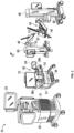
FIG. 1 is a schematic illustration of a surgical robotic system including a control tower, a console, and one or more surgical robotic arms each disposed on a mobile cart according to an embodiment of the present disclosure; -
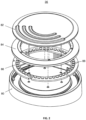
FIG. 2 is a perspective view, with parts separated, of a foot pedal according to an embodiment of the present disclosure; -
FIG. 3 is a top view of a printed circuit board assembly with LEDs and a color sensor according to an embodiment of the present disclosure; -
FIG. 4 is a spectrum of sensitivity of the color sensor according to an embodiment of the present disclosure; -
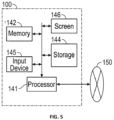
FIG. 5 is a schematic diagram of a computing device for color sensor characterization, calibration, and threshold-setting according to an embodiment of the present disclosure; -
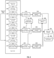
FIG. 6 is a flowchart of a method for generating a calibration matrix for calibrating a color sensor according to an embodiment of the present disclosure; -
FIG. 7 is a flowchart of a method for color classification using the calibration matrix according to an embodiment of the present disclosure; -
FIG. 8 is a hue-saturation distribution before correction using the method according to one embodiment of the present disclosure; -
FIG. 9 is hue-saturation distribution after correction using the method according to one embodiment of the present disclosure; and -
FIG. 10 is a threshold for color classification in a hue-saturation plane according to one embodiment of the present disclosure. - Embodiments of the presently disclosed surgical robotic system are described in detail with reference to the drawings, in which reference numerals designate identical or corresponding elements in each of the several views.
- With reference to
FIG. 1 , a surgicalrobotic system 10 includes acontrol tower 20, which is connected to all the components of the surgicalrobotic system 10 including asurgeon console 30 and one or moremobile carts 60. Each of themobile carts 60 includes asetup arm 62 holding arobotic arm 40. An instrument drive unit (IDU) 52 is held by therobotic arm 40 and asurgical instrument 50 is removably coupled to the IDU 52. Therobotic arms 40 also couple to themobile carts 60. Therobotic system 10 may include any number ofmobile carts 60 and/orrobotic arms 40. - The
surgical instrument 50 is configured for use during minimally invasive surgical procedures. In embodiments, thesurgical instrument 50 may be configured for open surgical procedures. In further embodiments, thesurgical instrument 50 may be an electrosurgical forceps configured to seal tissue by compressing tissue between jaw members and applying electrosurgical current thereto. In yet further embodiments, thesurgical instrument 50 may be a surgical stapler including a pair of jaws configured to grasp and clamp tissue while deploying a plurality of tissue fasteners, e.g., staples, and cutting stapled tissue. In yet further embodiments, thesurgical instrument 50 may be a surgical clip applier including a pair of jaws configured apply a surgical clip onto tissue. - One of the
robotic arms 40 may include alaparoscopic camera 51 configured to capture video of the surgical site. Thelaparoscopic camera 51 may be a stereoscopic endoscope configured to capture two side-by-side (i.e., left and right) images of the surgical site to produce a video stream of the surgical scene. Thelaparoscopic camera 51 is coupled to an image processing device, which may be disposed within thecontrol tower 20 and is configured to receive the video feed from thelaparoscopic camera 51 and output the processed video stream. - The
surgeon console 30 includes afirst screen 32, which displays a video feed of the surgical site provided bycamera 51 of thesurgical instrument 50 disposed on therobotic arm 40, and asecond screen 34, which displays a user interface for controlling the surgicalrobotic system 10. Thefirst screen 32 andsecond screen 34 may be touchscreens allowing for displaying various graphical user inputs. - The
surgeon console 30 also includes a plurality of user interface devices, such asfoot pedals 36 and a pair ofhand controllers robotic arms 40. The surgeon console further includes an armrest 33 used to support clinician's arms while operating thehand controllers - The
control tower 20 includes ascreen 23, which may be a touchscreen, and outputs on the graphical user interfaces (GUIs). Thecontrol tower 20 also acts as an interface between thesurgeon console 30 and one or morerobotic arms 40. In particular, thecontrol tower 20 is configured to control therobotic arms 40, such as to move therobotic arms 40 and the correspondingsurgical instrument 50, based on a set of programmable instructions and/or input commands from thesurgeon console 30, in such a way thatrobotic arms 40 and thesurgical instrument 50 execute a desired movement sequence in response to input from thefoot pedals 36 and thehand controllers foot pedals 36 may be used to enable and lock thehand controllers foot pedals 36 may be used to perform a clutching action on thehand controllers foot pedals 36, which disconnects (i.e., prevents movement inputs) thehand controllers 38a and/or 38b from therobotic arm 40 andcorresponding instrument 50 orcamera 51 attached thereto. This allows the user to reposition thehand controllers instrument 50 and/orcamera 51. This is useful when reaching control boundaries of the surgical space. - Each of the
control tower 20, thesurgical console 30, and therobotic arm 40 includes arespective computer computers - The
computers - With reference to
FIG. 2 , thefoot pedal 36 includes asupport base 80, acover 82 disposed over thesupport base 80. Thefoot pedal 36 also includes adiffusion layer 84 disposed below thecover 82 and is configured to diffuse the light evenly. A printed circuit board assembly (PCBA) 86 is disposed underneath thediffusion layer 84 and includes a plurality ofLEDs 88 arranged in a ring pattern as shown inFIG. 2 and3 . - Each of the
LEDs 88 may include three component LEDs that produce red, green and blue lights independently. When driven with different signals, these three component LEDs together produce the desired color needed. For simplicity, the driving signal is designated as (r, g, b). ThePCBA 86 also includes acolor sensor 89 as shown inFIG. 3 . - The
color sensor 89 is configured to sense red, green, blue, and white light. The readings from these channels are designated as [R, G, B, W] corresponding to sensed value from the red, green, blue, and white channels respectively.FIG. 4 shows a spectrum representing spectral sensitivity of thecolor sensor 89. The spectrum shows spectral overlap between the red, green, and blue. The readings from thecolor sensor 89 also have components from other channels. For example, even when the component LEDs are driven with (128,0,0) signal, where only the red LEDs are emitting light, the readings from the color sensor may include readings in other channels, e.g., [10763, 3497 2432]. In the example, the strongest response is from the red channel, which is 10763. However, the response from the green and blue channel are 3497 and 2432, respectively, which are significant since only narrow-band red light is emitted. - Similarly, when the component LEDs are driven with (0,128,0) signal, where only green LEDs are emitting light, the readings from the color sensor may be [5973,10319,2450]. When the component LEDs are driven with (0,0,128) signal, where only the blue LEDs are emitting light, the readings may be [4975,9385,11829]. The crosstalk for the green and blue light may be even more intense than red light. The crosstalk is normally present in the readings and makes the color classification a difficult task. Simple averaging over multiple samples does not eliminate crosstalk from the values. The present disclosure filters the crosstalk through a calibration process.
- With continued reference to the exemplary [R, G, B], readings from previous three activations of the LEDs are normalized by corresponding dominant color. After scaling, the readings are [1, 0.3249, 0.2259], [0.5788, 1, 0.2374] and [0.4206, 0.7934, 1] for driving the
LED 88 with red, green, and blue, respectively. With the normalized readings, the desired readings are [1, 0, 0], [0, 1, 0] and [0, 0, 1]. Thus, when the red LED is emitting light, the desired readings from thecolor sensor 89 contain only the components of red channel. The green and blue channels are near zero. Thus, when only green or blue LED is emitting light, the sensor readings are the same, where only the component of the corresponding channel is detected. - Normalized readings may be transferred to desired readings using a matrix A as shown below in formulas (1)-(3).


- Formulas (1)-(3) may also be expressed as following formulas (4)-(6).


- Formulas (4)-(6) may be further expressed as matrix formulas (7)-(9).


- Formulas (7)-(9) may then be merged into a single formula (10) below.

- Formula (10) may be rewritten and solved as formula (11).

- Plugging in the numbers from formulas (1), (2), and (3) into formula (11), a calibration matrix A is then defined by formula (12).

- The calibration matrix A may then be applied to the [R, G, B] readings prior to normalization. As an example, the initial readings are [10763, 3497, 2432], [5973, 10319, 2450] and [4975, 9385, 11829], respectively. The following formulas (13)-(15) show the corrected (i.e., calibrated) readings after applying the calibration matrix A to the readings from the
color sensor 89.


- As shown in (13), (14), and (15), after applying the calibration matrix A, the undesired systematic crosstalk can be filtered out from the color sensor readings. When the component LEDs are driven individually, desired calibration results are obtained. Similarly, when the component LEDs are driven with an arbitrary (r, g, b) signal, the calibration matrix may still be used given the following assumptions. First, the luminous intensity from each component LED changes linearly with the drive signal, the LED is driven in the linear range, and the light output changes linearly with driven current. Second, the readings from the
color sensor 89 changes linearly with light intensity. Third, the bandwidth of the LED light is narrow and there is little spectral overlap between red, green, and blue light emitted by these LEDs. The bandwidth of the LED light may be around 20-30 nm. The central wavelength of the red, green, and blue light may be 632, 527 and 470 nm, respectively. Thus, when only red component LED is emitting, the desired reading would have the component from red channel; components in green and blue channels are close to zero. - Under these assumptions, we can define the linear system as L, the LED drive signal as D, and the readings as S. When the component LEDs are driven individually with signal (128,0,0), (0,128,0) and (0,0,128), the system response may be modeled as follows in formulas (16)-(18).


- When the LEDs are driven with an arbitrary (r, g, b) signal, the input can be modeled using the formula (19).

- Applying the linear systems principle, the output from the system may be modeled by the formula (20).

- Applying the calibration matrix A to the output, the result is expressed by the formula (21).

- For individually driven red, green; and blue LEDs, the calibration matrix A can filter out the systematic crosstalk, as shown in formulas (13),(14) and (15). Those results may be generically modeled as equations (22)-(24).


- Plugging in formulas (22)-(24) into formula (21) results in formula (25).

- Assuming the response for individually driven component red, green, blue LEDs are approximately equal, then intensity may be expressed by formula (26).

- After applying the calibration matrix, the original driver signal in formula (19) may be obtained as formula (27).

- The above analysis is applicable to a
single foot pedal 36 with the calibration matrix as defined in formula (10). The calibration matrix for N number offoot pedals 36 may be expressed as formula (28).
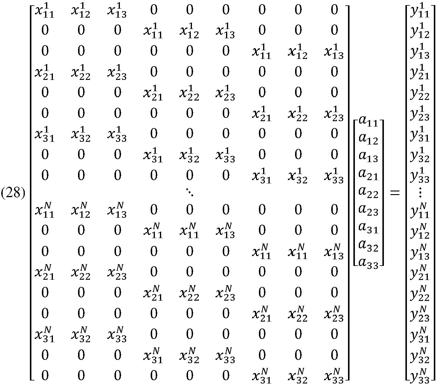
- The above formula (28) is over-constrained as there nine (9) unknowns, and 9N linear equations. The formula (28) may be simplified, and the matrix dimensions may be explicitly written in formula (29).

- This optimal solution to the formula (29) may be expressed as a least-square solution in formula (30).

- The above solution is obtained by the pseudo-inverse of the matrix M due to the fact the equation is over-constrained. An alternative way to calculate the calibration matrix for N
different foot pedals 36 is to calculate the average of normalized readings for formula (10). Then the calibration matrix may be calculated using the formula (31) where

- With reference to
FIG. 5 , acomputing device 100 for color sensor characterization, calibration, and threshold-setting may be configured to communicate with anetwork 150 such as a backbone LAN (local area network). Thecomputing device 100 includes aprocessor 141, amemory 142, astorage device 144, aninput device 145, and adisplay screen 146. Theprocessor 141 is connected to each of the hardware components constituting thecomputing device 100. - The
input device 145 may be any suitable user input device such as a keyboard, a touch screen, or a pointing device that can be operated by the operator and send input signals according to an operation to theprocessor 141. Theprocessor 141 may be configured to perform operations, calculations, and/or sets of instructions described in the disclosure and may be a hardware processor, a field programmable gate array (FPGA), a digital signal processor (DSP), a central processing unit (CPU), a microprocessor, and combinations thereof. If an instruction is input by an operator such as a physician operating theinput device 145, theprocessor 141 executes a program stored in thememory 142. Theprocessor 141 is configured to load software instructions stored in thestorage device 144 and/or transferred from thenetwork 150 or a removable storage device (not shown) into thememory 142 to execute such instructions. Thememory 142 may be a transitory storage device such as RAM (random access memory) and the like and is used as working memory for theprocessor 141 and used to temporarily store data. - The
storage device 144 is a non-transitory storage device, e.g., hard disc drive, flash storage, etc. Thestorage device 144 is a storage device in which programs installed in the computing device 100 (including an application program as well as an OS (operating system)) and data are stored. Also, the OS provides a GUI (graphical user interface) that displays information to the operator so that the operator can perform operations through theinput device 145. Thescreen 146 may be any suitable monitor and may include a touchscreen that is configured to display the GUI. - The methods for
calibrating LEDs 88 of thefoot pedals 36 according to the present disclosure are implemented as software instructions stored in thestorage device 144 and executable by theprocessor 141 of thecomputing device 100. With reference toFIG. 6 , a method for generating a calibration matrix includes driving red LED only with (128, 0, 0) atstep 200, by setting the driving signal of the red LED to the middle level, the green LED to zero, the blue LED to zero, and obtaining the color measurement atstep 202 at the color sensor 209. The measurements are then scaled against the red channel as [1, Gr/Rr, Br/Rr, Wr] atstep 204. The method also includes driving the green LED only with (0, 128, 0) signal atstep 206, by setting the driving signal of the red LED to zero, the green LED to the middle level, the blue LED to zero. Atstep 208, the color measurement is obtained and scaled against the green channel as [Rg/Gg, 1, Bg/Gg, Wg] atstep 210. The method further includes driving the blue LED only with (0, 0, 128) atstep 212 by setting the driving signal of the red LED to zero, the green LED to zero, the blue LED to middle level. Atstep 214, the color measurement is obtained at thecolor sensor 89 and the measurement is scaled against the blue channel as [Rb/Bb,Gb/Bb, 1, Wb] atstep 216. - Steps 200-216 may be repeated for each of a plurality of
different foot pedals 36 for N number of times to obtain N samples of [1, Gr/Rr, Br/Rr, Wr], [Rg/Gg, 1, Bg/Gg, Wg], and [Rb/Bb, Gb/Bb, 1, Wb], atsteps steps step 230, the average of the scaled readings is used to calculate the calibration matrix for thefoot pedals 36 using the formula (31) above. - Alternatively, the calibration matrix, i.e., pseudoinverse calibration matrix, may be calculated directly from the data, i.e., without calculating the mean at
step 232. The unscaled readings can be collected as [Rr, Gr, Br, Wr], [Rg, Gg, Bg, Wg], and [Rb, Gb, Bb, Wb]. The method may further include calculating an average and standard deviation of these unscaled readings. The method also includes simulating additional colors based on linear theory. Monte Carlo simulation may then be used atstep 234 to generate large samples of simulated foot pedals. Atstep 236, the data from the simulations is then used to generate thresholds for color classification. The thresholds are based on hue and saturation [H, S, W] by converting RGB values from the calibration matrix. - With reference to
FIG. 7 , a method for determining color classification of thefoot pedal 36 based on the calibration matrix includes driving theLED 88 of thefoot pedal 36 to the intended color atstep 300 and obtaining color measurements as [R, G, B, W] atstep 302. The measured color in [R, G, B] color space is converted to [H, S, V] color space atstep 304 and then compared to [H, S, W] thresholds atstep 306. If the converted color measurements are above the threshold, then thecomputing device 100 may output an alert that the color reproduction of the foot pedal is not accurate. - The method also includes calculating corrected readings through a calibration matrix as [R*, G*, B*]'=abs(A[R, G, B]') at
step 308 and converting [R*, G*, B*] in RGB color space to [H*, S*, V*] in HSV color space atstep 310. The method further includes applying H*, S*, and W thresholds for color classification atstep 312. If the converted color measurements are above the threshold, then thecomputing device 100 may output an alert that the color reproduction of the foot pedal is not accurate. The method ofFIG. 7 may be performed during the manufacturing process to ensure accurate color of thefoot pedal 36. - In one embodiment, five different colors may be generated to differentiate different foot pedals. 36 The color and corresponding drive signal of the
LEDs 88 are listed in the flowing table 1.Table 1 Color Drive Signal blue (0, 0, 255) yellow (192, 192, 0) green (0, 235, 16) magenta (128, 0, 128) white (170, 170, 170) - In order to properly set the classification threshold in the HSV color space, Monte Carlo simulation may be performed based on the statistic distribution of [Rr, Gr, Br, Wr], [Rg, Gg, Bg, Wg], and [Rb, Gb, Bb, Wb] as defined in previous steps. For example, around 100 such samples may be collected. Based on these samples, around 10,000
foot pedals 36 may be simulated to explore the spreads of parameters. For these simulated samples, the distribution of the five colors before correction in the hue saturation plane is shown inFIG. 8 . These distributions are calculated directly from the simulated readings without applying the calibration matrix. All the colors are clustered close to the center (left figure) instead of the edge of the color ring (right figure). This is due to crosstalk in the readings, which skews the color significantly. - After applying the calibration matrix, which is derived from the 100 samples, the distribution of the colors after correction in the hue-saturation plane is shown in
FIG. 9 . The distribution of those four colors is much closer to the edge of the color ring, and white is closer to the center. These distributions are closer to standard color distribution, which is displayed on the right side of the figure. - From the distribution in the hue-saturation plane after applying the calibration matrix, and the statistical analysis of the corrected [H*, S*, V*], it is straightforward to set up the classification thresholds for hue and saturation.
FIG. 10 shows one such example for the thresholds. With such thresholds, the projected manufacturing yield of thefoot pedals 36 and accuracy of the classification accuracy are summarized in the following table 2.Table 2 metric method magenta blue yellow green white accuracy prior 69.61 99.52 99.52 97.21 94.98 accuracy proposed 98.73 99.65 99.72 99.39 97.48 yield prior 69.61 99.52 99.52 98.06 94.98 yield proposed 98.73 99.65 99.72 99.39 99.30 - Table 2 demonstrates that applying a calibration matrix can significantly improve the accuracy and yield for some colors. Furthermore, this simulation is based on samples that already passed the quality check. Only less than 5 percent of the samples are drawn from failed units. For some specific batches, when calibration matrix is generated from that population, it can improve the classification accuracy and manufacturing yield even more dramatically.
- While the present calibration disclosure was described with respect to foot pedals of a surgical robotic system, the color calibration and verification methods disclosed herein may be used to verify color accuracy of any LED-based light source.
- It will be understood that various modifications may be made to the embodiments disclosed herein. Therefore, the above description should not be construed as limiting, but merely as exemplifications of various embodiments. Those skilled in the art will envision other modifications within the scope and spirit of the claims appended thereto.
- The invention may be described by reference to the following numbered paragraphs:-
- 1. A method for generating a calibration parameter for light sources, the method comprising:
- activating at least one LED of a plurality of multicolor LEDs of a light source;
- measuring a color of the at least one LED in a first color space;
- scaling the color of the at least one LED relative to the plurality of multicolor LEDs;
- obtaining a plurality of scaled color measurements; and
- calculating a calibration matrix based on the plurality of scaled color measurements.
- 2. The method according to
paragraph 1, wherein the first color space is a red, green, blue (RGB) color space and the calibration matrix is a 3x3 matrix of adjustment values. - 3. The method according to
paragraph 1, further comprising:
calculating a mean of the plurality of scaled color measurements. - 4. The method according to paragraph 3, further comprising:
calculating a standard deviation of the plurality of scaled color measurements. - 5. The method according to
paragraph 4, wherein calculating the calibration matrix is based on the mean and standard deviation of the plurality of scaled color measurements. - 6. The method according to
paragraph 1, further comprising simulating a plurality of simulated color measurements using a Monte Carlo simulation. - 7. The method according to
paragraph 1, further comprising:
generating a plurality of calibration thresholds in a second color space. - 8. The method according to paragraph 7, wherein the second color space is a hue, saturation, value (HSV) color space.
- 9. A method for calibrating a light source, the method comprising:
- activating at least one LED of a plurality of multicolor LEDs of a light source;
- measuring a color of the at least one LED in a first color space;
- converting the measured color using a calibration matrix to a calibrated first color space measurement;
- converting the calibrated first color space measurement to a second color space values;
- comparing the second color space values to thresholds derived from the calibration matrix; and
- outputting a calibration failure message in response to the second color space values exceeding the thresholds.
- 10. The method according to paragraph 9, wherein the first color space is a red, green, blue (RGB) color space.
- 11. The method according to paragraph 9, wherein the second color space is a hue, saturation, value (HSV) color space.
- 12. The method according to paragraph 9, wherein the calibration matrix is a 3x3 matrix of adjustment values.
- 13. The method according to paragraph 9, wherein the plurality of multicolor LEDs are disposed in a foot pedal of a surgeon console for a surgical robotic system.
- 14. A computer-readable medium including instructions executable by a processor that are configured to cause a computing system to perform a method comprising:
- activating at least one LED of a plurality of multicolor LEDs of a light source;
- measuring a color of the at least one LED in a first color space;
- scaling the color of the at least one LED relative to the plurality of multicolor LEDs;
- obtaining a plurality of scaled color measurements; and
- calculating a calibration matrix based on the plurality of scaled color measurements.
- 15. The computer-readable medium according to
paragraph 14, wherein the first color space is a red, green, blue (RGB) color space and the calibration matrix is a 3x3 matrix of adjustment values. - 16. The computer-readable medium according to
paragraph 14, wherein the method further comprises:
calculating a mean of the plurality of scaled color measurements. - 17. The computer-readable medium according to paragraph 16, wherein the method further comprises:
calculating a standard deviation of the plurality of scaled color measurements. - 18. The computer-readable medium according to paragraph 17, wherein calculating the calibration matrix is based on the mean and standard deviation of the plurality of scaled color measurements.
- 19. The computer-readable medium according to
paragraph 14, wherein the method further comprises simulating a plurality of simulated color measurements using a Monte Carlo simulation. - 20. The computer-readable medium according to
paragraph 14, wherein the method further comprises:
generating a plurality of calibration thresholds in a second color space.
Claims (15)
- A method for generating a calibration parameter for light sources, the method comprising:activating at least one LED of a plurality of multicolor LEDs of a light source;measuring a color of the at least one LED in a first color space;scaling the color of the at least one LED relative to the plurality of multicolor LEDs;obtaining a plurality of scaled color measurements; andcalculating a calibration matrix based on the plurality of scaled color measurements.
- The method according to claim 1, wherein the first color space is a red, green, blue (RGB) color space and the calibration matrix is a 3x3 matrix of adjustment values.
- The method according to claim 1 or claim 2, further comprising:
calculating a mean of the plurality of scaled color measurements. - The method according to claim 3, further comprising:
calculating a standard deviation of the plurality of scaled color measurement; preferably wherein calculating the calibration matrix is based on the mean and standard deviation of the plurality of scaled color measurements. - The method according to any preceding claim, further comprising simulating a plurality of simulated color measurements using a Monte Carlo simulation.
- The method according to any preceding claim, further comprising:
generating a plurality of calibration thresholds in a second color space; preferably wherein the second color space is a hue, saturation, value (HSV) color space. - A method for calibrating a light source, the method comprising:activating at least one LED of a plurality of multicolor LEDs of a light source;measuring a color of the at least one LED in a first color space;converting the measured color using a calibration matrix to a calibrated first color space measurement;converting the calibrated first color space measurement to a second color space values;comparing the second color space values to thresholds derived from the calibration matrix; andoutputting a calibration failure message in response to the second color space values exceeding the thresholds.
- The method according to claim 7, wherein the first color space is a red, green, blue (RGB) color space.
- The method according to claim 7 or claim 8, wherein the second color space is a hue, saturation, value (HSV) color space.
- The method according to any of claims 7 to 9, wherein the calibration matrix is a 3x3 matrix of adjustment values; preferably wherein the plurality of multicolor LEDs are disposed in a foot pedal of a surgeon console for a surgical robotic system.
- A computer-readable medium including instructions executable by a processor that are configured to cause a computing system to perform a method comprising:activating at least one LED of a plurality of multicolor LEDs of a light source;measuring a color of the at least one LED in a first color space;scaling the color of the at least one LED relative to the plurality of multicolor LEDs;obtaining a plurality of scaled color measurements; andcalculating a calibration matrix based on the plurality of scaled color measurements.
- The computer-readable medium according to claim 11, wherein the first color space is a red, green, blue (RGB) color space and the calibration matrix is a 3x3 matrix of adjustment values.
- The computer-readable medium according to claim 11 or claim 12, wherein the method further comprises:
calculating a mean of the plurality of scaled color measurements; preferably wherein the method further comprises:
calculating a standard deviation of the plurality of scaled color measurements. - The computer-readable medium according to claim 13, wherein calculating the calibration matrix is based on the mean and standard deviation of the plurality of scaled color measurements.
- The computer-readable medium according to any of claims 11 to 14 wherein the method further comprises simulating a plurality of simulated color measurements using a Monte Carlo simulation; and/or wherein the method further comprises:
generating a plurality of calibration thresholds in a second color space.
Applications Claiming Priority (2)
| Application Number | Priority Date | Filing Date | Title |
|---|---|---|---|
| US202263325781P | 2022-03-31 | 2022-03-31 | |
| US18/124,361 US12613134B2 (en) | 2022-03-31 | 2023-03-21 | System and method for color sensor characterization, calibration and threshold-setting |
Publications (2)
| Publication Number | Publication Date |
|---|---|
| EP4255118A1 true EP4255118A1 (en) | 2023-10-04 |
| EP4255118B1 EP4255118B1 (en) | 2025-12-17 |
Family
ID=86184880
Family Applications (1)
| Application Number | Title | Priority Date | Filing Date |
|---|---|---|---|
| EP23165110.0A Active EP4255118B1 (en) | 2022-03-31 | 2023-03-29 | System and method for color sensor characterization, calibration, and threshold-setting |
Country Status (2)
| Country | Link |
|---|---|
| US (1) | US12613134B2 (en) |
| EP (1) | EP4255118B1 (en) |
Families Citing this family (1)
| Publication number | Priority date | Publication date | Assignee | Title |
|---|---|---|---|---|
| ES3062138T3 (en) * | 2020-11-20 | 2026-04-08 | Signify Holding Bv | Lighting system calibration |
Citations (2)
| Publication number | Priority date | Publication date | Assignee | Title |
|---|---|---|---|---|
| US20080103714A1 (en) * | 2006-10-25 | 2008-05-01 | Renaissance Lighting, Inc. | Calibration method and apparatus for lighting fixtures using multiple spectrum light sources and light mixing |
| CA2848855A1 (en) * | 2014-04-10 | 2015-10-10 | Institut National D'optique | Operation of a led lighting system at a target output color using a color sensor |
Family Cites Families (402)
| Publication number | Priority date | Publication date | Assignee | Title |
|---|---|---|---|---|
| US37165A (en) | 1862-12-16 | 1862-12-16 | Improvement in gearing for machinery | |
| US3273562A (en) | 1960-02-24 | 1966-09-20 | Rene G Le Vaux | Skin and surgical clips |
| US3209754A (en) | 1961-08-10 | 1965-10-05 | Ernest C Wood | Surgical clip |
| US3499591A (en) | 1967-06-23 | 1970-03-10 | United States Surgical Corp | Instrument for placing lateral gastro-intestinal anastomoses |
| GB1218076A (en) | 1968-02-20 | 1971-01-06 | Carr Fastener Co Ltd | Backing strip for attachment to an article made of foamed plastics |
| US3744495A (en) | 1970-01-02 | 1973-07-10 | M Johnson | Method of securing prolapsed vagina in cattle |
| US3862631A (en) | 1973-05-16 | 1975-01-28 | Down Bros | Surgical implants |
| US3949924A (en) | 1974-10-18 | 1976-04-13 | United States Surgical Corporation | Surgical stapling instrument |
| US4060089A (en) | 1975-09-03 | 1977-11-29 | United States Surgical Corporation | Surgical fastening method and device therefor |
| US4217902A (en) | 1977-05-02 | 1980-08-19 | March Alfred L | Hemostatic clip |
| US4204623A (en) | 1978-07-17 | 1980-05-27 | United States Surgical Corporation | Manually powered surgical stapling instrument |
| US4263903A (en) | 1979-01-08 | 1981-04-28 | Richards Manufacturing Co., Inc. | Medical staple means |
| US4275813A (en) | 1979-06-04 | 1981-06-30 | United States Surgical Corporation | Coherent surgical staple array |
| US4429695A (en) | 1980-02-05 | 1984-02-07 | United States Surgical Corporation | Surgical instruments |
| US4428376A (en) | 1980-05-02 | 1984-01-31 | Ethicon Inc. | Plastic surgical staple |
| US4331277A (en) | 1980-05-23 | 1982-05-25 | United States Surgical Corporation | Self-contained gas powered surgical stapler |
| US4606343A (en) | 1980-08-18 | 1986-08-19 | United States Surgical Corporation | Self-powered surgical fastening instrument |
| CA1149106A (en) | 1980-11-10 | 1983-07-05 | Henk W. Wevers | Bone clip |
| US4485816A (en) | 1981-06-25 | 1984-12-04 | Alchemia | Shape-memory surgical staple apparatus and method for use in surgical suturing |
| US4454875A (en) | 1982-04-15 | 1984-06-19 | Techmedica, Inc. | Osteal medical staple |
| ATE29772T1 (en) | 1982-04-20 | 1987-10-15 | Ferag Ag | DRIVE DEVICE FOR THE SHAFT OF A MOBILE EQUIPMENT. |
| US4485817A (en) | 1982-05-28 | 1984-12-04 | United States Surgical Corporation | Surgical stapler apparatus with flexible shaft |
| US5928222A (en) | 1982-08-06 | 1999-07-27 | Kleinerman; Marcos Y. | Fiber optic sensing techniques in laser medicine |
| US4488523A (en) | 1982-09-24 | 1984-12-18 | United States Surgical Corporation | Flexible, hydraulically actuated device for applying surgical fasteners |
| US4662371A (en) | 1983-01-26 | 1987-05-05 | Whipple Terry L | Surgical instrument |
| US4522206A (en) | 1983-01-26 | 1985-06-11 | Dyonics, Inc. | Surgical instrument |
| US4535772A (en) | 1983-03-10 | 1985-08-20 | Kells Medical, Incorporated | Skin closure device |
| US4570623A (en) | 1983-06-02 | 1986-02-18 | Pfizer Hospital Products Group Inc. | Arched bridge staple |
| US4534350A (en) | 1983-06-20 | 1985-08-13 | Ethicon, Inc. | Two-piece tissue fastener with compressible leg staple and retaining receiver |
| US4627437A (en) | 1983-06-20 | 1986-12-09 | Ethicon, Inc. | Method of applying a fastener to tissue with a pair of hollow needles |
| US4508253A (en) | 1983-10-04 | 1985-04-02 | United States Surgical Corporation | Surgical fastener applying apparatus |
| US4610383A (en) | 1983-10-14 | 1986-09-09 | Senmed, Inc. | Disposable linear surgical stapler |
| US4612923A (en) | 1983-12-01 | 1986-09-23 | Ethicon, Inc. | Glass-filled, absorbable surgical devices |
| US4635637A (en) | 1984-03-29 | 1987-01-13 | Schreiber Saul N | Surgical suture |
| US4612933A (en) | 1984-03-30 | 1986-09-23 | Senmed, Inc. | Multiple-load cartridge assembly for a linear surgical stapling instrument |
| US4606344A (en) | 1984-07-16 | 1986-08-19 | Ethicon, Inc. | Surgical instrument for applying fasteners having improved gap indicating means (Case V) |
| US4566620A (en) | 1984-10-19 | 1986-01-28 | United States Surgical Corporation | Articulated surgical fastener applying apparatus |
| US4705038A (en) | 1985-01-23 | 1987-11-10 | Dyonics, Inc. | Surgical system for powered instruments |
| US4712550A (en) | 1985-04-08 | 1987-12-15 | Sinnett Kevin B | Retinal tack |
| US4807628A (en) | 1985-04-26 | 1989-02-28 | Edward Weck & Company, Inc. | Method and apparatus for storing, dispensing, and applying surgical staples |
| US4671280A (en) | 1985-05-13 | 1987-06-09 | Ethicon, Inc. | Surgical fastening device and method for manufacture |
| USD286442S (en) | 1985-12-31 | 1986-10-28 | United States Surgical Corporation | Surgical fastener |
| US4731058A (en) | 1986-05-22 | 1988-03-15 | Pharmacia Deltec, Inc. | Drug delivery system |
| US4724839A (en) | 1986-09-18 | 1988-02-16 | Ethicon, Inc. | Surgical fastening systems made from polymeric materials |
| US4719917A (en) | 1987-02-17 | 1988-01-19 | Minnesota Mining And Manufacturing Company | Surgical staple |
| US4852558A (en) | 1987-07-29 | 1989-08-01 | Outerbridge Howard K G | Compressible bone staple |
| US4805617A (en) | 1987-11-05 | 1989-02-21 | Ethicon, Inc. | Surgical fastening systems made from polymeric materials |
| DE3805179A1 (en) | 1988-02-19 | 1989-08-31 | Wolf Gmbh Richard | DEVICE WITH A ROTATING DRIVEN SURGICAL INSTRUMENT |
| IT215084Z2 (en) | 1988-08-03 | 1990-07-30 | Torino A | VARIABLE EXCURSION CAMBRA |
| US4960420A (en) | 1988-08-23 | 1990-10-02 | Marlowe Goble E | Channel ligament clamp and system |
| ES2011110A6 (en) | 1988-09-02 | 1989-12-16 | Lopez Hervas Pedro | Hydraulic device with flexible body for surgical anastomosts |
| FR2637370B1 (en) | 1988-10-04 | 1991-04-12 | Gir | DEVICE FOR CONTROLLING TEMPERATURES CONTAINING AT LEAST ONE SHAPE MEMORY ALLOY ELEMENT |
| US4990153A (en) | 1988-10-07 | 1991-02-05 | Ophthalmic Ventures Limited Partnership | Surgical suturing system and probe assembly |
| US4892244A (en) | 1988-11-07 | 1990-01-09 | Ethicon, Inc. | Surgical stapler cartridge lockout device |
| US4994073A (en) | 1989-02-22 | 1991-02-19 | United States Surgical Corp. | Skin fastener |
| US5089009A (en) | 1989-06-27 | 1992-02-18 | United States Surgical Corporation | Inwardly biased skin fastener |
| US5040715B1 (en) | 1989-05-26 | 1994-04-05 | United States Surgical Corp | Apparatus and method for placing staples in laparoscopic or endoscopic procedures |
| US5318221A (en) | 1989-05-26 | 1994-06-07 | United States Surgical Corporation | Apparatus and method for placing staples in laparoscopic or endoscopic procedures |
| GB8924806D0 (en) | 1989-11-03 | 1989-12-20 | Neoligaments Ltd | Prosthectic ligament system |
| US5725529A (en) | 1990-09-25 | 1998-03-10 | Innovasive Devices, Inc. | Bone fastener |
| US5114399A (en) | 1990-10-01 | 1992-05-19 | Intramed Laboratories | Surgical device |
| US5108422A (en) | 1990-10-22 | 1992-04-28 | United States Surgical Corporation | Skin fastener |
| FR2668361A1 (en) | 1990-10-30 | 1992-04-30 | Mai Christian | OSTEOSYNTHESIS CLIP AND PLATE WITH SELF-RETENTIVE DYNAMIC COMPRESSION. |
| US5129570A (en) | 1990-11-30 | 1992-07-14 | Ethicon, Inc. | Surgical stapler |
| US5690675A (en) | 1991-02-13 | 1997-11-25 | Fusion Medical Technologies, Inc. | Methods for sealing of staples and other fasteners in tissue |
| US5571285A (en) | 1991-02-19 | 1996-11-05 | Ethicon, Inc. | Surgical staple for insertion into tissue |
| US6580086B1 (en) | 1999-08-26 | 2003-06-17 | Masimo Corporation | Shielded optical probe and method |
| US5720753A (en) | 1991-03-22 | 1998-02-24 | United States Surgical Corporation | Orthopedic fastener |
| US5065929A (en) | 1991-04-01 | 1991-11-19 | Ethicon, Inc. | Surgical stapler with locking means |
| US5359993A (en) | 1992-12-31 | 1994-11-01 | Symbiosis Corporation | Apparatus for counting the number of times a medical instrument has been used |
| US5203864A (en) | 1991-04-05 | 1993-04-20 | Phillips Edward H | Surgical fastener system |
| US5413267A (en) | 1991-05-14 | 1995-05-09 | United States Surgical Corporation | Surgical stapler with spent cartridge sensing and lockout means |
| US5391166A (en) | 1991-06-07 | 1995-02-21 | Hemostatic Surgery Corporation | Bi-polar electrosurgical endoscopic instruments having a detachable working end |
| US5207697A (en) | 1991-06-27 | 1993-05-04 | Stryker Corporation | Battery powered surgical handpiece |
| US5282829A (en) | 1991-08-15 | 1994-02-01 | United States Surgical Corporation | Hollow body implants |
| US5350104A (en) | 1991-08-23 | 1994-09-27 | Ethicon, Inc. | Sealing means for endoscopic surgical anastomosis stapling instrument |
| US5307976A (en) | 1991-10-18 | 1994-05-03 | Ethicon, Inc. | Linear stapling mechanism with cutting means |
| AU660712B2 (en) | 1991-10-18 | 1995-07-06 | United States Surgical Corporation | Apparatus for applying surgical fasteners |
| US5326013A (en) | 1991-10-18 | 1994-07-05 | United States Surgical Corporation | Self contained gas powered surgical apparatus |
| US6250532B1 (en) | 1991-10-18 | 2001-06-26 | United States Surgical Corporation | Surgical stapling apparatus |
| US5332142A (en) | 1991-10-18 | 1994-07-26 | Ethicon, Inc. | Linear stapling mechanism with cutting means |
| US5497933A (en) | 1991-10-18 | 1996-03-12 | United States Surgical Corporation | Apparatus and method for applying surgical staples to attach an object to body tissue |
| US5312023A (en) | 1991-10-18 | 1994-05-17 | United States Surgical Corporation | Self contained gas powered surgical apparatus |
| US5364001A (en) | 1991-10-18 | 1994-11-15 | United States Surgical Corporation | Self contained gas powered surgical apparatus |
| US5356064A (en) | 1991-10-18 | 1994-10-18 | United States Surgical Corporation | Apparatus and method for applying surgical staples to attach an object to body tissue |
| US5197649A (en) | 1991-10-29 | 1993-03-30 | The Trustees Of Columbia University In The City Of New York | Gastrointestinal endoscoptic stapler |
| US5665085A (en) | 1991-11-01 | 1997-09-09 | Medical Scientific, Inc. | Electrosurgical cutting tool |
| US5713896A (en) | 1991-11-01 | 1998-02-03 | Medical Scientific, Inc. | Impedance feedback electrosurgical system |
| US5531744A (en) | 1991-11-01 | 1996-07-02 | Medical Scientific, Inc. | Alternative current pathways for bipolar surgical cutting tool |
| US5383874A (en) | 1991-11-08 | 1995-01-24 | Ep Technologies, Inc. | Systems for identifying catheters and monitoring their use |
| US5383880A (en) | 1992-01-17 | 1995-01-24 | Ethicon, Inc. | Endoscopic surgical system with sensing means |
| US5271543A (en) | 1992-02-07 | 1993-12-21 | Ethicon, Inc. | Surgical anastomosis stapling instrument with flexible support shaft and anvil adjusting mechanism |
| US5350355A (en) | 1992-02-14 | 1994-09-27 | Automated Medical Instruments, Inc. | Automated surgical instrument |
| US5389098A (en) | 1992-05-19 | 1995-02-14 | Olympus Optical Co., Ltd. | Surgical device for stapling and/or fastening body tissues |
| US5658300A (en) | 1992-06-04 | 1997-08-19 | Olympus Optical Co., Ltd. | Tissue fixing surgical instrument, tissue-fixing device, and method of fixing tissues |
| JPH0647050A (en) | 1992-06-04 | 1994-02-22 | Olympus Optical Co Ltd | Tissue suture and ligature device |
| US5330486A (en) | 1992-07-29 | 1994-07-19 | Wilk Peter J | Laparoscopic or endoscopic anastomosis technique and associated instruments |
| US5258008A (en) | 1992-07-29 | 1993-11-02 | Wilk Peter J | Surgical stapling device and associated method |
| US5609560A (en) | 1992-08-19 | 1997-03-11 | Olympus Optical Co., Ltd. | Medical operation device control system for controlling a operation devices accessed respectively by ID codes |
| CA2437773C (en) | 1992-09-21 | 2005-02-22 | United States Surgical Corporation | Device for applying a meniscal staple |
| US5601224A (en) | 1992-10-09 | 1997-02-11 | Ethicon, Inc. | Surgical instrument |
| US5381943A (en) | 1992-10-09 | 1995-01-17 | Ethicon, Inc. | Endoscopic surgical stapling instrument with pivotable and rotatable staple cartridge |
| US5662662A (en) | 1992-10-09 | 1997-09-02 | Ethicon Endo-Surgery, Inc. | Surgical instrument and method |
| US5431323A (en) | 1992-10-09 | 1995-07-11 | Ethicon, Inc. | Endoscopic surgical instrument with pivotable and rotatable staple cartridge |
| US5300081A (en) | 1992-10-09 | 1994-04-05 | United States Surgical Corporation | Surgical clip applier having clip advancement control |
| US5400267A (en) | 1992-12-08 | 1995-03-21 | Hemostatix Corporation | Local in-device memory feature for electrically powered medical equipment |
| US5403312A (en) | 1993-07-22 | 1995-04-04 | Ethicon, Inc. | Electrosurgical hemostatic device |
| US5558671A (en) | 1993-07-22 | 1996-09-24 | Yates; David C. | Impedance feedback monitor for electrosurgical instrument |
| US5313935A (en) | 1992-12-31 | 1994-05-24 | Symbiosis Corporation | Apparatus for counting the number of times a surgical instrument has been used |
| US5380334A (en) | 1993-02-17 | 1995-01-10 | Smith & Nephew Dyonics, Inc. | Soft tissue anchors and systems for implantation |
| US5342396A (en) | 1993-03-02 | 1994-08-30 | Cook Melvin S | Staples |
| FR2704135B1 (en) | 1993-04-19 | 1995-07-07 | Savornin Claude | OSTEOSYNTHESIS STAPLE. |
| US5467911A (en) | 1993-04-27 | 1995-11-21 | Olympus Optical Co., Ltd. | Surgical device for stapling and fastening body tissues |
| US5447265A (en) | 1993-04-30 | 1995-09-05 | Minnesota Mining And Manufacturing Company | Laparoscopic surgical instrument with a mechanism for preventing its entry into the abdominal cavity once it is depleted and removed from the abdominal cavity |
| US5342376A (en) | 1993-05-03 | 1994-08-30 | Dermagraphics, Inc. | Inserting device for a barbed tissue connector |
| CA2124109A1 (en) | 1993-05-24 | 1994-11-25 | Mark T. Byrne | Endoscopic surgical instrument with electromagnetic sensor |
| EP0703758B1 (en) | 1993-06-04 | 2002-10-23 | Smith & Nephew, Inc. | Surgical screw and washer |
| US5500000A (en) | 1993-07-01 | 1996-03-19 | United States Surgical Corporation | Soft tissue repair system and method |
| US5810811A (en) | 1993-07-22 | 1998-09-22 | Ethicon Endo-Surgery, Inc. | Electrosurgical hemostatic device |
| US5693051A (en) | 1993-07-22 | 1997-12-02 | Ethicon Endo-Surgery, Inc. | Electrosurgical hemostatic device with adaptive electrodes |
| GR940100335A (en) | 1993-07-22 | 1996-05-22 | Ethicon Inc. | Electrosurgical device for placing staples. |
| US5503320A (en) | 1993-08-19 | 1996-04-02 | United States Surgical Corporation | Surgical apparatus with indicator |
| US5405344A (en) | 1993-09-30 | 1995-04-11 | Ethicon, Inc. | Articulable socket joint assembly for an endoscopic instrument for surgical fastner track therefor |
| US5560532A (en) | 1993-10-08 | 1996-10-01 | United States Surgical Corporation | Apparatus and method for applying surgical staples to body tissue |
| CA2133377C (en) | 1993-10-08 | 2004-09-14 | H. Jonathan Tovey | Surgical suturing apparatus with loading mechanism |
| US5487499A (en) | 1993-10-08 | 1996-01-30 | United States Surgical Corporation | Surgical apparatus for applying surgical fasteners including a counter |
| US5607436A (en) | 1993-10-08 | 1997-03-04 | United States Surgical Corporation | Apparatus for applying surgical clips |
| US5478344A (en) | 1993-10-08 | 1995-12-26 | United States Surgical Corporation | Surgical suturing apparatus with loading mechanism |
| US5991650A (en) | 1993-10-15 | 1999-11-23 | Ep Technologies, Inc. | Surface coatings for catheters, direct contacting diagnostic and therapeutic devices |
| US5584835A (en) | 1993-10-18 | 1996-12-17 | Greenfield; Jon B. | Soft tissue to bone fixation device and method |
| US5830121A (en) | 1993-10-27 | 1998-11-03 | Asahi Kogaku Kogyo Kabushiki Kaisha | Endoscopic apparatus having an endoscope and a peripheral device wherein total usage of the endoscope is quantified and recorded |
| US5507743A (en) | 1993-11-08 | 1996-04-16 | Zomed International | Coiled RF electrode treatment apparatus |
| DE4340570C2 (en) | 1993-11-29 | 2003-04-10 | Hilti Ag | Driving device for setting fasteners in recording materials |
| US5782397A (en) | 1994-01-04 | 1998-07-21 | Alpha Surgical Technologies, Inc. | Stapling device |
| AU1011595A (en) | 1994-01-13 | 1995-07-20 | Ethicon Inc. | Spiral surgical tack |
| US6165169A (en) | 1994-03-04 | 2000-12-26 | Ep Technologies, Inc. | Systems and methods for identifying the physical, mechanical, and functional attributes of multiple electrode arrays |
| US5526822A (en) | 1994-03-24 | 1996-06-18 | Biopsys Medical, Inc. | Method and apparatus for automated biopsy and collection of soft tissue |
| CA2145723A1 (en) | 1994-03-30 | 1995-10-01 | Steven W. Hamblin | Surgical stapling instrument with remotely articulated stapling head assembly on rotatable support shaft |
| US5695524A (en) | 1994-04-05 | 1997-12-09 | Tracor Aerospace, Inc. | Constant width, adjustable grip, staple apparatus and method |
| US5715987A (en) | 1994-04-05 | 1998-02-10 | Tracor Incorporated | Constant width, adjustable grip, staple apparatus and method |
| US5482100A (en) | 1994-04-06 | 1996-01-09 | Newell Operating Company | Cordless, balanced venetian blind or shade with consistent variable force spring motor |
| US5529235A (en) | 1994-04-28 | 1996-06-25 | Ethicon Endo-Surgery, Inc. | Identification device for surgical instrument |
| CA2148667A1 (en) | 1994-05-05 | 1995-11-06 | Carlo A. Mililli | Self-contained powered surgical apparatus |
| AU694225B2 (en) | 1994-08-02 | 1998-07-16 | Ethicon Endo-Surgery, Inc. | Ultrasonic hemostatic and cutting instrument |
| EP0699418A1 (en) | 1994-08-05 | 1996-03-06 | United States Surgical Corporation | Self-contained powered surgical apparatus |
| US5779130A (en) | 1994-08-05 | 1998-07-14 | United States Surgical Corporation | Self-contained powered surgical apparatus |
| US5571116A (en) | 1994-10-02 | 1996-11-05 | United States Surgical Corporation | Non-invasive treatment of gastroesophageal reflux disease |
| WO1996014020A1 (en) | 1994-11-02 | 1996-05-17 | Olympus Optical Co. Ltd. | Endoscope operative instrument |
| US5868760A (en) | 1994-12-07 | 1999-02-09 | Mcguckin, Jr.; James F. | Method and apparatus for endolumenally resectioning tissue |
| US5713505A (en) | 1996-05-13 | 1998-02-03 | Ethicon Endo-Surgery, Inc. | Articulation transmission mechanism for surgical instruments |
| US5632432A (en) | 1994-12-19 | 1997-05-27 | Ethicon Endo-Surgery, Inc. | Surgical instrument |
| US5704534A (en) | 1994-12-19 | 1998-01-06 | Ethicon Endo-Surgery, Inc. | Articulation assembly for surgical instruments |
| KR100189281B1 (en) | 1994-12-27 | 1999-06-01 | 미따라이 하지메 | Speed reducer |
| US5575799A (en) | 1995-03-30 | 1996-11-19 | United States Surgical Corporation | Articulating surgical apparatus |
| US5624452A (en) | 1995-04-07 | 1997-04-29 | Ethicon Endo-Surgery, Inc. | Hemostatic surgical cutting or stapling instrument |
| US5634926A (en) | 1995-04-25 | 1997-06-03 | Jobe; Richard P. | Surgical bone fixation apparatus |
| US5630540A (en) | 1995-05-24 | 1997-05-20 | United States Surgical Corporation | Surgical staple and staple drive member |
| US6293943B1 (en) | 1995-06-07 | 2001-09-25 | Ep Technologies, Inc. | Tissue heating and ablation systems and methods which predict maximum tissue temperature |
| US5649956A (en) | 1995-06-07 | 1997-07-22 | Sri International | System and method for releasably holding a surgical instrument |
| US5667513A (en) | 1995-06-07 | 1997-09-16 | Smith & Nephew Dyonics Inc. | Soft tissue anchor delivery apparatus |
| US5868737A (en) | 1995-06-09 | 1999-02-09 | Engineering Research & Associates, Inc. | Apparatus and method for determining ablation |
| US6113592A (en) | 1995-06-09 | 2000-09-05 | Engineering & Research Associates, Inc. | Apparatus and method for controlling ablation depth |
| GB9512128D0 (en) | 1995-06-15 | 1995-08-16 | Ethicon Inc | Surgical pins |
| US6080150A (en) | 1995-08-15 | 2000-06-27 | Rita Medical Systems, Inc. | Cell necrosis apparatus |
| US6132425A (en) | 1995-08-15 | 2000-10-17 | Gough; Edward J. | Cell necrosis apparatus |
| US6032849A (en) | 1995-08-28 | 2000-03-07 | United States Surgical | Surgical stapler |
| US5762256A (en) | 1995-08-28 | 1998-06-09 | United States Surgical Corporation | Surgical stapler |
| EP0852708B1 (en) | 1995-09-29 | 2001-09-12 | International Business Machines Corporation | Mechanical signal processor based on micromechanical oscillators and intelligent acoustic detectors and systems based thereon |
| US5813404A (en) | 1995-10-20 | 1998-09-29 | Aspect Medical Systems, Inc. | Electrode connector system |
| US5997552A (en) | 1995-10-20 | 1999-12-07 | United States Surgical Corporation | Meniscal fastener applying device |
| US5980518A (en) | 1995-10-27 | 1999-11-09 | Carr; William N. | Microcautery surgical tool |
| US5941442A (en) | 1995-10-27 | 1999-08-24 | United States Surgical | Surgical stapler |
| FR2741796B1 (en) | 1995-11-30 | 1998-03-27 | Tornier Sa | DEVICE FOR FIXING A PROSTHESIS AND PARTICULARLY A GLENOIDAL PROSTHESIS OF OMOPLATE |
| EP0786204B1 (en) | 1996-01-23 | 1998-10-28 | Diehl Ident GmbH | Device for fitting birds with a transponder |
| US6015417A (en) | 1996-01-25 | 2000-01-18 | Reynolds, Jr.; Walker | Surgical fastener |
| US5695506A (en) | 1996-02-06 | 1997-12-09 | Devices For Vascular Intervention | Catheter device with a flexible housing |
| US5727569A (en) | 1996-02-20 | 1998-03-17 | Cardiothoracic Systems, Inc. | Surgical devices for imposing a negative pressure to fix the position of cardiac tissue during surgery |
| US6010054A (en) | 1996-02-20 | 2000-01-04 | Imagyn Medical Technologies | Linear stapling instrument with improved staple cartridge |
| US6063095A (en) | 1996-02-20 | 2000-05-16 | Computer Motion, Inc. | Method and apparatus for performing minimally invasive surgical procedures |
| US5730757A (en) | 1996-02-20 | 1998-03-24 | Cardiothoracic Systems, Inc. | Access platform for internal mammary dissection |
| US5976171A (en) | 1996-02-20 | 1999-11-02 | Cardiothoracic Systems, Inc. | Access platform for internal mammary dissection |
| US5911727A (en) | 1996-02-20 | 1999-06-15 | Cardiothoracic Systems, Inc. | Stitcher |
| US6699177B1 (en) | 1996-02-20 | 2004-03-02 | Computer Motion, Inc. | Method and apparatus for performing minimally invasive surgical procedures |
| CA2198036C (en) | 1996-02-20 | 2000-12-05 | Charles S. Taylor | Access platform for internal mammary dissection |
| US6436107B1 (en) | 1996-02-20 | 2002-08-20 | Computer Motion, Inc. | Method and apparatus for performing minimally invasive surgical procedures |
| US5855583A (en) | 1996-02-20 | 1999-01-05 | Computer Motion, Inc. | Method and apparatus for performing minimally invasive cardiac procedures |
| US5810240A (en) | 1996-03-15 | 1998-09-22 | United States Surgical Corporation | Surgical fastener applying device |
| AUPN957296A0 (en) | 1996-04-30 | 1996-05-23 | Cardiac Crc Nominees Pty Limited | A system for simultaneous unipolar multi-electrode ablation |
| US5823066A (en) | 1996-05-13 | 1998-10-20 | Ethicon Endo-Surgery, Inc. | Articulation transmission mechanism for surgical instruments |
| US6258111B1 (en) | 1997-10-03 | 2001-07-10 | Scieran Technologies, Inc. | Apparatus and method for performing ophthalmic procedures |
| US6017354A (en) | 1996-08-15 | 2000-01-25 | Stryker Corporation | Integrated system for powered surgical tools |
| EP0918551B1 (en) | 1996-08-15 | 2004-11-03 | Deka Products Limited Partnership | Medical irrigation pump and system |
| US5759171A (en) | 1996-09-27 | 1998-06-02 | Thermogenesis Corp. | Sprayer for fibrin glue |
| US6109500A (en) | 1996-10-04 | 2000-08-29 | United States Surgical Corporation | Lockout mechanism for a surgical stapler |
| US6063098A (en) | 1996-12-23 | 2000-05-16 | Houser; Kevin | Articulable ultrasonic surgical apparatus |
| US5849023A (en) | 1996-12-27 | 1998-12-15 | Mericle; Robert William | Disposable remote flexible drive cutting apparatus |
| US5861005A (en) | 1997-02-11 | 1999-01-19 | X-Site, L.L.C. | Arterial stapling device |
| ES2202575T3 (en) | 1997-02-28 | 2004-04-01 | Synthes Ag Chur | IMPLANT FOR OSTEOSYNTHESIS. |
| US6063078A (en) | 1997-03-12 | 2000-05-16 | Medtronic, Inc. | Method and apparatus for tissue ablation |
| US5944717A (en) | 1997-05-12 | 1999-08-31 | The Regents Of The University Of California | Micromachined electrical cauterizer |
| USH2037H1 (en) | 1997-05-14 | 2002-07-02 | David C. Yates | Electrosurgical hemostatic device including an anvil |
| USH1904H (en) | 1997-05-14 | 2000-10-03 | Ethicon Endo-Surgery, Inc. | Electrosurgical hemostatic method and device |
| US5849028A (en) | 1997-05-16 | 1998-12-15 | Irvine Biomedical, Inc. | Catheter and method for radiofrequency ablation of cardiac tissue |
| US6231565B1 (en) | 1997-06-18 | 2001-05-15 | United States Surgical Corporation | Robotic arm DLUs for performing surgical tasks |
| SE9702679D0 (en) | 1997-07-11 | 1997-07-11 | Siemens Elema Ab | Device for calculating the number of uses of a sensor |
| US6013077A (en) | 1997-07-31 | 2000-01-11 | Harwin; Steven F. | Orthopaedic posting device |
| WO1999007441A1 (en) | 1997-08-11 | 1999-02-18 | Mayer Paul W | Motorized motion-canceling suture tool holder |
| US5865361A (en) | 1997-09-23 | 1999-02-02 | United States Surgical Corporation | Surgical stapling apparatus |
| US5980548A (en) | 1997-10-29 | 1999-11-09 | Kensey Nash Corporation | Transmyocardial revascularization system |
| US6015416A (en) | 1998-02-26 | 2000-01-18 | Ethicon Endo-Surgery, Inc. | Surgical anastomosis instrument |
| US6051007A (en) | 1998-03-02 | 2000-04-18 | Corvascular, Inc. | Sternal closure device and instruments therefor |
| US6030410A (en) | 1998-05-18 | 2000-02-29 | Zurbruegg; Heinz Robert | Sternal closure technique and kit for performing same |
| AUPP360798A0 (en) | 1998-05-20 | 1998-06-11 | Ultimate Medical Pty. Ltd. | Heat cycle indicating device |
| US6478210B2 (en) | 2000-10-25 | 2002-11-12 | Scimed Life Systems, Inc. | Method and device for full thickness resectioning of an organ |
| US6126058A (en) | 1998-06-19 | 2000-10-03 | Scimed Life Systems, Inc. | Method and device for full thickness resectioning of an organ |
| US6601749B2 (en) | 1998-06-19 | 2003-08-05 | Scimed Life Systems, Inc. | Multi fire full thickness resectioning device |
| SE9802674D0 (en) | 1998-08-05 | 1998-08-05 | Siemens Elema Ab | Apparatus for repeated registration of thermal cycles, as a part for medical use undergoes |
| US6355066B1 (en) | 1998-08-19 | 2002-03-12 | Andrew C. Kim | Anterior cruciate ligament reconstruction hamstring tendon fixation system |
| US6166538A (en) | 1998-08-26 | 2000-12-26 | Linvatec Corporation | Autoclave cycle monitor for autoclaved instruments |
| US6245065B1 (en) | 1998-09-10 | 2001-06-12 | Scimed Life Systems, Inc. | Systems and methods for controlling power in an electrosurgical probe |
| US6123702A (en) | 1998-09-10 | 2000-09-26 | Scimed Life Systems, Inc. | Systems and methods for controlling power in an electrosurgical probe |
| US6210406B1 (en) | 1998-12-03 | 2001-04-03 | Cordis Webster, Inc. | Split tip electrode catheter and signal processing RF ablation system |
| US6228534B1 (en) | 1998-12-21 | 2001-05-08 | Wilson Greatbatch Ltd. | Annealing of mixed metal oxide electrodes to reduce polarization resistance |
| WO2000040158A2 (en) | 1999-01-08 | 2000-07-13 | Influence Medical Technologies, Ltd. | Surgical tack |
| US6127811A (en) | 1999-01-12 | 2000-10-03 | Vlsi Technology, Inc. | Micro-electromechanical system and voltage shifter, method of synchronizing an electronic system and a micromechanical system of a micro-electromechanical system |
| US5992724A (en) | 1999-02-04 | 1999-11-30 | Snyder; Thomas W. | Stapler with staple quantity indicator |
| US6288534B1 (en) | 1999-02-10 | 2001-09-11 | Cts Corporation | Non-contacting throttle valve position sensor |
| US6083242A (en) | 1999-02-17 | 2000-07-04 | Holobeam, Inc. | Surgical staples with deformation zones of non-uniform cross section |
| US6308089B1 (en) | 1999-04-14 | 2001-10-23 | O.B. Scientific, Inc. | Limited use medical probe |
| US6248117B1 (en) | 1999-04-16 | 2001-06-19 | Vital Access Corp | Anastomosis apparatus for use in intraluminally directed vascular anastomosis |
| US6443973B1 (en) | 1999-06-02 | 2002-09-03 | Power Medical Interventions, Inc. | Electromechanical driver device for use with anastomosing, stapling, and resecting instruments |
| US6315184B1 (en) | 1999-06-02 | 2001-11-13 | Powermed, Inc. | Stapling device for use with an electromechanical driver device for use with anastomosing, stapling, and resecting instruments |
| US6981941B2 (en) | 1999-06-02 | 2006-01-03 | Power Medical Interventions | Electro-mechanical surgical device |
| US6716233B1 (en) | 1999-06-02 | 2004-04-06 | Power Medical Interventions, Inc. | Electromechanical driver and remote surgical instrument attachment having computer assisted control capabilities |
| US6793652B1 (en) | 1999-06-02 | 2004-09-21 | Power Medical Interventions, Inc. | Electro-mechanical surgical device |
| US8292888B2 (en) | 2001-04-20 | 2012-10-23 | Tyco Healthcare Group Lp | Bipolar or ultrasonic surgical device |
| US8025199B2 (en) | 2004-02-23 | 2011-09-27 | Tyco Healthcare Group Lp | Surgical cutting and stapling device |
| US8241322B2 (en) | 2005-07-27 | 2012-08-14 | Tyco Healthcare Group Lp | Surgical device |
| US7032798B2 (en) | 1999-06-02 | 2006-04-25 | Power Medical Interventions, Inc. | Electro-mechanical surgical device |
| US6264087B1 (en) | 1999-07-12 | 2001-07-24 | Powermed, Inc. | Expanding parallel jaw device for use with an electromechanical driver device |
| US6616821B2 (en) | 1999-06-08 | 2003-09-09 | Broadley Technologies Corporation | Reference electrode having a microfluidic flowing liquid junction |
| US6193501B1 (en) | 1999-07-06 | 2001-02-27 | The Board Of Trustees Of The University Of Illinois | Microcombustor having submillimeter critical dimensions |
| US6497707B1 (en) | 1999-07-23 | 2002-12-24 | Ethicon, Inc. | Graft fixation device combination |
| US6402766B2 (en) | 1999-07-23 | 2002-06-11 | Ethicon, Inc. | Graft fixation device combination |
| US6179840B1 (en) | 1999-07-23 | 2001-01-30 | Ethicon, Inc. | Graft fixation device and method |
| US6436110B2 (en) | 1999-07-23 | 2002-08-20 | Ethicon, Inc. | Method of securing a graft using a graft fixation device |
| US6447517B1 (en) | 1999-07-23 | 2002-09-10 | Ethicon, Inc. | Instrument for inserting graft fixation device |
| US6364884B1 (en) | 1999-07-23 | 2002-04-02 | Ethicon, Inc. | Method of securing a graft using a graft fixation device |
| US6451007B1 (en) | 1999-07-29 | 2002-09-17 | Dale E. Koop | Thermal quenching of tissue |
| US6554852B1 (en) | 1999-08-25 | 2003-04-29 | Michael A. Oberlander | Multi-anchor suture |
| US6515273B2 (en) | 1999-08-26 | 2003-02-04 | Masimo Corporation | System for indicating the expiration of the useful operating life of a pulse oximetry sensor |
| US6611793B1 (en) | 1999-09-07 | 2003-08-26 | Scimed Life Systems, Inc. | Systems and methods to identify and disable re-use single use devices based on detecting environmental changes |
| US6237604B1 (en) | 1999-09-07 | 2001-05-29 | Scimed Life Systems, Inc. | Systems and methods for preventing automatic identification of re-used single use devices |
| US6387092B1 (en) | 1999-09-07 | 2002-05-14 | Scimed Life Systems, Inc. | Systems and methods to identify and disable re-used single use devices based on time elapsed from first therapeutic use |
| US6651669B1 (en) | 1999-09-07 | 2003-11-25 | Scimed Life Systems, Inc. | Systems and methods to identify and disable re-used single use devices based on cataloging catheter usage |
| US6264653B1 (en) | 1999-09-24 | 2001-07-24 | C. R. Band, Inc. | System and method for gauging the amount of electrode-tissue contact using pulsed radio frequency energy |
| US6281471B1 (en) | 1999-12-28 | 2001-08-28 | Gsi Lumonics, Inc. | Energy-efficient, laser-based method and system for processing target material |
| US6290701B1 (en) | 2000-01-11 | 2001-09-18 | Albert Enayati | Bioabsorbable rivet bone fastener |
| GB0425765D0 (en) | 2004-11-23 | 2004-12-22 | Gyrus Medical Ltd | Tissue resurfacing |
| US6533157B1 (en) | 2000-02-22 | 2003-03-18 | Power Medical Interventions, Inc. | Tissue stapling attachment for use with an electromechanical driver device |
| IL139788A (en) | 2000-11-20 | 2006-10-05 | Minelu Zonnenschein | Stapler for endoscopes |
| US20030120306A1 (en) | 2000-04-21 | 2003-06-26 | Vascular Control System | Method and apparatus for the detection and occlusion of blood vessels |
| US6425903B1 (en) | 2000-05-09 | 2002-07-30 | James W. Voegele | Implantable surgical marker |
| US6669705B2 (en) | 2000-05-17 | 2003-12-30 | Axya Medical, Inc. | Apparatus and method for welding sutures |
| US6696008B2 (en) | 2000-05-25 | 2004-02-24 | Westar Photonics Inc. | Maskless laser beam patterning ablation of multilayered structures with continuous monitoring of ablation |
| ATE338519T1 (en) | 2000-06-14 | 2006-09-15 | Teppo Jaervinen | FIXATION ANCHORS |
| JP3897962B2 (en) | 2000-07-19 | 2007-03-28 | 株式会社モリタ製作所 | Identification-type instrument body, identification-type adapter, identification-type tube, and medical device using these |
| US7220232B2 (en) | 2000-08-24 | 2007-05-22 | Timi 3 Systems, Inc. | Method for delivering ultrasonic energy |
| US7241270B2 (en) | 2000-08-24 | 2007-07-10 | Timi 3 Systems Inc. | Systems and methods for monitoring and enabling use of a medical instrument |
| US7335169B2 (en) | 2000-08-24 | 2008-02-26 | Timi 3 Systems, Inc. | Systems and methods for delivering ultrasound energy at an output power level that remains essentially constant despite variations in transducer impedance |
| US6830174B2 (en) | 2000-08-30 | 2004-12-14 | Cerebral Vascular Applications, Inc. | Medical instrument |
| US6817508B1 (en) | 2000-10-13 | 2004-11-16 | Tyco Healthcare Group, Lp | Surgical stapling device |
| US6908472B2 (en) | 2000-10-20 | 2005-06-21 | Ethicon Endo-Surgery, Inc. | Apparatus and method for altering generator functions in an ultrasonic surgical system |
| AU2002232798B2 (en) | 2000-10-23 | 2006-01-05 | Covidien Lp | Absorbable fastener and applying apparatus |
| US6656177B2 (en) | 2000-10-23 | 2003-12-02 | Csaba Truckai | Electrosurgical systems and techniques for sealing tissue |
| US20050010235A1 (en) | 2003-07-09 | 2005-01-13 | Vandusseldorp Gregg A. | Surgical device |
| US7232445B2 (en) | 2000-12-06 | 2007-06-19 | Id, Llc | Apparatus for the endoluminal treatment of gastroesophageal reflux disease (GERD) |
| US6412279B1 (en) | 2000-12-20 | 2002-07-02 | Caterpillar Inc. | Twin turbine exhaust gas re-circulation system having a second stage variable nozzle turbine |
| US20020111641A1 (en) | 2001-01-08 | 2002-08-15 | Incisive Surgical, Inc. | Bioabsorbable surgical clip with engageable expansion structure |
| JP4194842B2 (en) | 2001-01-18 | 2008-12-10 | ザ リージェンツ オブ ザ ユニバーシティ オブ カリフォルニア | Minimally invasive glaucoma surgical instruments and methods |
| KR200228502Y1 (en) | 2001-01-26 | 2001-06-15 | 구본희 | A medical staple for joining bone |
| US7905897B2 (en) | 2001-03-14 | 2011-03-15 | Tyco Healthcare Group Lp | Trocar device |
| DE10147145C2 (en) | 2001-09-25 | 2003-12-18 | Kunz Reiner | Multi-function instrument for micro-invasive surgery |
| EP2347722B1 (en) | 2001-10-05 | 2014-09-17 | Covidien LP | Surgical stapling device |
| US7464847B2 (en) | 2005-06-03 | 2008-12-16 | Tyco Healthcare Group Lp | Surgical stapler with timer and feedback display |
| US10285694B2 (en) | 2001-10-20 | 2019-05-14 | Covidien Lp | Surgical stapler with timer and feedback display |
| US20030090201A1 (en) | 2001-11-13 | 2003-05-15 | Kuan-Chang Peng | Organic electro-luminescence device |
| US20030114851A1 (en) | 2001-12-13 | 2003-06-19 | Csaba Truckai | Electrosurgical jaws for controlled application of clamping pressure |
| US6601748B1 (en) | 2001-12-15 | 2003-08-05 | Modern Medical Equip. Mfg., Ltd. | Surgical stapler |
| US6602252B2 (en) | 2002-01-03 | 2003-08-05 | Starion Instruments Corporation | Combined dissecting, cauterizing, and stapling device |
| US20040049172A1 (en) | 2002-03-18 | 2004-03-11 | Root Thomas V. | Reusable instruments and related systems and methods |
| WO2003090630A2 (en) | 2002-04-25 | 2003-11-06 | Tyco Healthcare Group, Lp | Surgical instruments including micro-electromechanical systems (mems) |
| JP2004034243A (en) | 2002-07-04 | 2004-02-05 | Max Co Ltd | Remaining staple quantity detecting device for electric stapler |
| JP2004070199A (en) | 2002-08-09 | 2004-03-04 | Konica Minolta Holdings Inc | Concentrated color developing composition for silver halide photographic sensitive material and processing method using the same |
| US6926636B2 (en) | 2002-09-25 | 2005-08-09 | Jerry Luper | Gear driven power converter |
| US7338504B2 (en) | 2002-10-03 | 2008-03-04 | Gibbens Group, L.L.C. | Cycling suturing and knot-tying device |
| EP2430985B1 (en) | 2002-10-04 | 2017-06-14 | Covidien LP | Pneumatic powered surgical stapling device |
| FR2849589A1 (en) | 2003-01-07 | 2004-07-09 | 2R Invest | Thermo-retractable clip heating device control method for surgery, involves blocking electronic control circuit of device when predetermined criterion is recognized, and unlocking device using external information stored in IC card |
| US7044352B2 (en) | 2003-05-20 | 2006-05-16 | Ethicon Endo-Surgery, Inc. | Surgical stapling instrument having a single lockout mechanism for prevention of firing |
| US7380695B2 (en) | 2003-05-20 | 2008-06-03 | Ethicon Endo-Surgery, Inc. | Surgical stapling instrument having a single lockout mechanism for prevention of firing |
| US7380696B2 (en) | 2003-05-20 | 2008-06-03 | Ethicon Endo-Surgery, Inc. | Articulating surgical stapling instrument incorporating a two-piece E-beam firing mechanism |
| US20070084897A1 (en) | 2003-05-20 | 2007-04-19 | Shelton Frederick E Iv | Articulating surgical stapling instrument incorporating a two-piece e-beam firing mechanism |
| US7140528B2 (en) | 2003-05-20 | 2006-11-28 | Ethicon Endo-Surgery, Inc. | Surgical stapling instrument having an electroactive polymer actuated single lockout mechanism for prevention of firing |
| US6988649B2 (en) | 2003-05-20 | 2006-01-24 | Ethicon Endo-Surgery, Inc. | Surgical stapling instrument having a spent cartridge lockout |
| US6964363B2 (en) | 2003-07-09 | 2005-11-15 | Ethicon Endo-Surgery, Inc. | Surgical stapling instrument having articulation joint support plates for supporting a firing bar |
| US7055731B2 (en) | 2003-07-09 | 2006-06-06 | Ethicon Endo-Surgery Inc. | Surgical stapling instrument incorporating a tapered firing bar for increased flexibility around the articulation joint |
| US6981628B2 (en) | 2003-07-09 | 2006-01-03 | Ethicon Endo-Surgery, Inc. | Surgical instrument with a lateral-moving articulation control |
| US7111769B2 (en) | 2003-07-09 | 2006-09-26 | Ethicon Endo-Surgery, Inc. | Surgical instrument incorporating an articulation mechanism having rotation about the longitudinal axis |
| US7364061B2 (en) | 2003-09-29 | 2008-04-29 | Ethicon Endo-Surgery, Inc. | Surgical stapling instrument incorporating a multistroke firing position indicator and retraction mechanism |
| US6905057B2 (en) | 2003-09-29 | 2005-06-14 | Ethicon Endo-Surgery, Inc. | Surgical stapling instrument incorporating a firing mechanism having a linked rack transmission |
| US7083075B2 (en) | 2003-09-29 | 2006-08-01 | Ethicon Endo-Surgery, Inc. | Multi-stroke mechanism with automatic end of stroke retraction |
| US7303108B2 (en) | 2003-09-29 | 2007-12-04 | Ethicon Endo-Surgery, Inc. | Surgical stapling instrument incorporating a multi-stroke firing mechanism with a flexible rack |
| US6959852B2 (en) | 2003-09-29 | 2005-11-01 | Ethicon Endo-Surgery, Inc. | Surgical stapling instrument with multistroke firing incorporating an anti-backup mechanism |
| US7000819B2 (en) | 2003-09-29 | 2006-02-21 | Ethicon Endo-Surgery, Inc. | Surgical stapling instrument having multistroke firing incorporating a traction-biased ratcheting mechanism |
| US7434715B2 (en) | 2003-09-29 | 2008-10-14 | Ethicon Endo-Surgery, Inc. | Surgical stapling instrument having multistroke firing with opening lockout |
| US20090090763A1 (en) | 2007-10-05 | 2009-04-09 | Tyco Healthcare Group Lp | Powered surgical stapling device |
| JP2007509717A (en) | 2003-10-28 | 2007-04-19 | ザ ユーエービー リサーチ ファウンデーション | Electrosurgical control system |
| US7118564B2 (en) | 2003-11-26 | 2006-10-10 | Ethicon Endo-Surgery, Inc. | Medical treatment system with energy delivery device for limiting reuse |
| US8156387B2 (en) | 2003-12-19 | 2012-04-10 | Pitney Bowes Inc. | Method and system for error manipulation |
| US7766207B2 (en) | 2003-12-30 | 2010-08-03 | Ethicon Endo-Surgery, Inc. | Articulating curved cutter stapler |
| US20050143759A1 (en) | 2003-12-30 | 2005-06-30 | Kelly William D. | Curved cutter stapler shaped for male pelvis |
| US7549563B2 (en) | 2003-12-30 | 2009-06-23 | Ethicon Endo-Surgery, Inc. | Rotating curved cutter stapler |
| US20050139636A1 (en) | 2003-12-30 | 2005-06-30 | Schwemberger Richard F. | Replaceable cartridge module for a surgical stapling and cutting instrument |
| US20050177176A1 (en) | 2004-02-05 | 2005-08-11 | Craig Gerbi | Single-fold system for tissue approximation and fixation |
| US7097089B2 (en) | 2004-02-17 | 2006-08-29 | Tyco Healthcare Group Lp | Surgical stapling apparatus with locking mechanism |
| DE602005000891T2 (en) | 2004-02-17 | 2008-01-17 | Tyco Healthcare Group Lp, Norwalk | Surgical stapler with locking mechanism |
| US7059508B2 (en) | 2004-06-30 | 2006-06-13 | Ethicon Endo-Surgery, Inc. | Surgical stapling instrument incorporating an uneven multistroke firing mechanism having a rotary transmission |
| US7143925B2 (en) | 2004-07-28 | 2006-12-05 | Ethicon Endo-Surgery, Inc. | Surgical instrument incorporating EAP blocking lockout mechanism |
| US7487899B2 (en) | 2004-07-28 | 2009-02-10 | Ethicon Endo-Surgery, Inc. | Surgical instrument incorporating EAP complete firing system lockout mechanism |
| US7143926B2 (en) | 2005-02-07 | 2006-12-05 | Ethicon Endo-Surgery, Inc. | Surgical stapling instrument incorporating a multi-stroke firing mechanism with return spring rotary manual retraction system |
| US7147138B2 (en) | 2004-07-28 | 2006-12-12 | Ethicon Endo-Surgery, Inc. | Surgical stapling instrument having an electroactive polymer actuated buttress deployment mechanism |
| US7128254B2 (en) | 2004-09-07 | 2006-10-31 | Ethicon Endo-Surgery, Inc. | Surgical stapling instrument incorporating a multistroke firing mechanism having a rotary slip-clutch transmission |
| JP2006081687A (en) | 2004-09-15 | 2006-03-30 | Max Co Ltd | Medical stapler |
| US7784663B2 (en) | 2005-03-17 | 2010-08-31 | Ethicon Endo-Surgery, Inc. | Surgical stapling instrument having load sensing control circuitry |
| EP3738521B1 (en) | 2005-06-03 | 2023-10-18 | Covidien LP | Surgical stapler with timer and feedback display |
| US8627995B2 (en) | 2006-05-19 | 2014-01-14 | Ethicon Endo-Sugery, Inc. | Electrically self-powered surgical instrument with cryptographic identification of interchangeable part |
| US8579176B2 (en) | 2005-07-26 | 2013-11-12 | Ethicon Endo-Surgery, Inc. | Surgical stapling and cutting device and method for using the device |
| WO2007014355A2 (en) | 2005-07-27 | 2007-02-01 | Power Medical Interventions, Inc. | Shaft, e.g., for an electro-mechanical surgical device |
| US7955352B2 (en) | 2005-08-05 | 2011-06-07 | Western Clinical Engineering, Ltd | Surgical tourniquet cuff for limiting usage to improve safety |
| US20070029363A1 (en) | 2005-08-07 | 2007-02-08 | Sergey Popov | Surgical apparatus with remote drive |
| US7886953B2 (en) | 2005-08-18 | 2011-02-15 | Ethicon Endo-Surgery, Inc. | Fired device lockout for a curved cutter stapler with a free moving trigger |
| US20070102472A1 (en) | 2005-11-04 | 2007-05-10 | Ethicon Endo-Surgery, Inc. | Electrosurgical stapling instrument with disposable severing / stapling unit |
| US7328828B2 (en) | 2005-11-04 | 2008-02-12 | Ethicon Endo-Surgery, Inc, | Lockout mechanisms and surgical instruments including same |
| US7246734B2 (en) | 2005-12-05 | 2007-07-24 | Ethicon Endo-Surgery, Inc. | Rotary hydraulic pump actuated multi-stroke surgical instrument |
| US7694809B2 (en) | 2005-12-06 | 2010-04-13 | Siemens Medical Solutions Usa, Inc. | Remote enabling/disabling of a limited-use medical device |
| US7835823B2 (en) | 2006-01-05 | 2010-11-16 | Intuitive Surgical Operations, Inc. | Method for tracking and reporting usage events to determine when preventive maintenance is due for a medical robotic system |
| US7670334B2 (en) | 2006-01-10 | 2010-03-02 | Ethicon Endo-Surgery, Inc. | Surgical instrument having an articulating end effector |
| US8186555B2 (en) | 2006-01-31 | 2012-05-29 | Ethicon Endo-Surgery, Inc. | Motor-driven surgical cutting and fastening instrument with mechanical closure system |
| US7464846B2 (en) | 2006-01-31 | 2008-12-16 | Ethicon Endo-Surgery, Inc. | Surgical instrument having a removable battery |
| US7416101B2 (en) | 2006-01-31 | 2008-08-26 | Ethicon Endo-Surgery, Inc. | Motor-driven surgical cutting and fastening instrument with loading force feedback |
| US7568603B2 (en) | 2006-01-31 | 2009-08-04 | Ethicon Endo-Surgery, Inc. | Motor-driven surgical cutting and fastening instrument with articulatable end effector |
| US7766210B2 (en) | 2006-01-31 | 2010-08-03 | Ethicon Endo-Surgery, Inc. | Motor-driven surgical cutting and fastening instrument with user feedback system |
| US7464849B2 (en) | 2006-01-31 | 2008-12-16 | Ethicon Endo-Surgery, Inc. | Electro-mechanical surgical instrument with closure system and anvil alignment components |
| US7422139B2 (en) | 2006-01-31 | 2008-09-09 | Ethicon Endo-Surgery, Inc. | Motor-driven surgical cutting fastening instrument with tactile position feedback |
| US20070175950A1 (en) | 2006-01-31 | 2007-08-02 | Shelton Frederick E Iv | Disposable staple cartridge having an anvil with tissue locator for use with a surgical cutting and fastening instrument and modular end effector system therefor |
| US7770775B2 (en) | 2006-01-31 | 2010-08-10 | Ethicon Endo-Surgery, Inc. | Motor-driven surgical cutting and fastening instrument with adaptive user feedback |
| US7644848B2 (en) | 2006-01-31 | 2010-01-12 | Ethicon Endo-Surgery, Inc. | Electronic lockouts and surgical instrument including same |
| US20070175951A1 (en) | 2006-01-31 | 2007-08-02 | Shelton Frederick E Iv | Gearing selector for a powered surgical cutting and fastening instrument |
| US20070175955A1 (en) | 2006-01-31 | 2007-08-02 | Shelton Frederick E Iv | Surgical cutting and fastening instrument with closure trigger locking mechanism |
| US8708213B2 (en) | 2006-01-31 | 2014-04-29 | Ethicon Endo-Surgery, Inc. | Surgical instrument having a feedback system |
| US20070219563A1 (en) | 2006-03-17 | 2007-09-20 | Voegele Aaron C | Reprocessing indicator ink for medical instruments |
| BRPI0709893A2 (en) | 2006-04-06 | 2011-07-26 | Synthes Gmbh | bone displacement apparatus and tissue displacement apparatus |
| WO2007137243A2 (en) | 2006-05-19 | 2007-11-29 | Applied Medical Resources Corporation | Surgical stapler |
| US7740159B2 (en) | 2006-08-02 | 2010-06-22 | Ethicon Endo-Surgery, Inc. | Pneumatically powered surgical cutting and fastening instrument with a variable control of the actuating rate of firing with mechanical power assist |
| US20080029574A1 (en) | 2006-08-02 | 2008-02-07 | Shelton Frederick E | Pneumatically powered surgical cutting and fastening instrument with actuator at distal end |
| US20080029575A1 (en) | 2006-08-02 | 2008-02-07 | Shelton Frederick E | Surgical cutting and fastening instrument with distally mounted pneumatically powered rotary drive member |
| US7481348B2 (en) | 2006-10-06 | 2009-01-27 | Tyco Healthcare Group Lp | Surgical instrument with articulating tool assembly |
| US8807414B2 (en) | 2006-10-06 | 2014-08-19 | Covidien Lp | System and method for non-contact electronic articulation sensing |
| US7721931B2 (en) | 2007-01-10 | 2010-05-25 | Ethicon Endo-Surgery, Inc. | Prevention of cartridge reuse in a surgical instrument |
| US8827133B2 (en) | 2007-01-11 | 2014-09-09 | Ethicon Endo-Surgery, Inc. | Surgical stapling device having supports for a flexible drive mechanism |
| US7422136B1 (en) | 2007-03-15 | 2008-09-09 | Tyco Healthcare Group Lp | Powered surgical stapling device |
| US7431188B1 (en) | 2007-03-15 | 2008-10-07 | Tyco Healthcare Group Lp | Surgical stapling apparatus with powered articulation |
| US8006885B2 (en) | 2007-04-09 | 2011-08-30 | Tyco Healthcare Group Lp | Surgical stapling apparatus with powered retraction |
| US20080255413A1 (en) | 2007-04-13 | 2008-10-16 | Michael Zemlok | Powered surgical instrument |
| US8800837B2 (en) | 2007-04-13 | 2014-08-12 | Covidien Lp | Powered surgical instrument |
| US7950560B2 (en) | 2007-04-13 | 2011-05-31 | Tyco Healthcare Group Lp | Powered surgical instrument |
| US7823760B2 (en) | 2007-05-01 | 2010-11-02 | Tyco Healthcare Group Lp | Powered surgical stapling device platform |
| US7931660B2 (en) | 2007-05-10 | 2011-04-26 | Tyco Healthcare Group Lp | Powered tacker instrument |
| US20090018624A1 (en) | 2007-07-13 | 2009-01-15 | Juniper Medical, Inc. | Limiting use of disposable system patient protection devices |
| US7556185B2 (en) | 2007-08-15 | 2009-07-07 | Tyco Healthcare Group Lp | Surgical instrument with flexible drive mechanism |
| DE102007044556A1 (en) | 2007-09-07 | 2009-03-12 | Arnold & Richter Cine Technik Gmbh & Co. Betriebs Kg | Method and device for adjusting the color or photometric properties of an LED lighting device |
| US20090090201A1 (en) | 2007-10-05 | 2009-04-09 | Tyco Healthcare Group Lp | Nutating Gear Drive Mechanism for Surgical Devices |
| US7922063B2 (en) | 2007-10-31 | 2011-04-12 | Tyco Healthcare Group, Lp | Powered surgical instrument |
| US7547869B2 (en) * | 2007-11-21 | 2009-06-16 | Avago Technologies Ecbu Ip (Singapore) Pte. Ltd. | Illumination system calibration and operation having a calibration matrix calculation based on a shift in color space |
| US7922061B2 (en) | 2008-05-21 | 2011-04-12 | Ethicon Endo-Surgery, Inc. | Surgical instrument with automatically reconfigurable articulating end effector |
| US8011551B2 (en) | 2008-07-01 | 2011-09-06 | Tyco Healthcare Group Lp | Retraction mechanism with clutch-less drive for use with a surgical apparatus |
| US8074858B2 (en) | 2008-07-17 | 2011-12-13 | Tyco Healthcare Group Lp | Surgical retraction mechanism |
| US8210411B2 (en) | 2008-09-23 | 2012-07-03 | Ethicon Endo-Surgery, Inc. | Motor-driven surgical cutting instrument |
| JP5334602B2 (en) | 2009-01-23 | 2013-11-06 | 三菱電機株式会社 | Color calibration system |
| US8708211B2 (en) | 2009-02-12 | 2014-04-29 | Covidien Lp | Powered surgical instrument with secondary circuit board |
| US8821514B2 (en) | 2009-06-08 | 2014-09-02 | Covidien Lp | Powered tack applier |
| US10383629B2 (en) | 2009-08-10 | 2019-08-20 | Covidien Lp | System and method for preventing reprocessing of a powered surgical instrument |
| WO2011106661A1 (en) * | 2010-02-25 | 2011-09-01 | B/E Aerospace, Inc. | Calibration method for led lighting systems |
| US20120211542A1 (en) | 2011-02-23 | 2012-08-23 | Tyco Healthcare Group I.P | Controlled tissue compression systems and methods |
| US9480492B2 (en) | 2011-10-25 | 2016-11-01 | Covidien Lp | Apparatus for endoscopic procedures |
| KR101272367B1 (en) | 2011-11-25 | 2013-06-07 | 박재열 | Calibration System of Image Display Device Using Transfer Functions And Calibration Method Thereof |
| US10492814B2 (en) | 2012-07-09 | 2019-12-03 | Covidien Lp | Apparatus for endoscopic procedures |
| US10722222B2 (en) | 2012-12-14 | 2020-07-28 | Covidien Lp | Surgical system including a plurality of handle assemblies |
| WO2015077493A1 (en) * | 2013-11-20 | 2015-05-28 | Digimarc Corporation | Sensor-synchronized spectrally-structured-light imaging |
| DE102016108754A1 (en) * | 2016-05-11 | 2017-11-16 | Schott Ag | Lighting device with consistent light characteristics |
| US10925135B2 (en) * | 2019-02-11 | 2021-02-16 | Crestron Electronics, Inc. | LED button calibration for a wall mounted control device |
| US12667440B2 (en) * | 2020-01-03 | 2026-06-30 | Auris Health, Inc. | Foot pedal assemblies with indicators for robotic medical systems |
-
2023
- 2023-03-21 US US18/124,361 patent/US12613134B2/en active Active
- 2023-03-29 EP EP23165110.0A patent/EP4255118B1/en active Active
Patent Citations (2)
| Publication number | Priority date | Publication date | Assignee | Title |
|---|---|---|---|---|
| US20080103714A1 (en) * | 2006-10-25 | 2008-05-01 | Renaissance Lighting, Inc. | Calibration method and apparatus for lighting fixtures using multiple spectrum light sources and light mixing |
| CA2848855A1 (en) * | 2014-04-10 | 2015-10-10 | Institut National D'optique | Operation of a led lighting system at a target output color using a color sensor |
Also Published As
| Publication number | Publication date |
|---|---|
| EP4255118B1 (en) | 2025-12-17 |
| US20230314215A1 (en) | 2023-10-05 |
| US12613134B2 (en) | 2026-04-28 |
Similar Documents
| Publication | Publication Date | Title |
|---|---|---|
| JP7512475B2 (en) | Interactive Surgical Systems | |
| JP7686926B2 (en) | Patient location and contact sensing utilizing a monopolar return pad electrode to provide situational awareness to the hub | |
| EP4408331B1 (en) | Surgical systems with intraluminal and extraluminal cooperative instruments | |
| US11510720B2 (en) | Managing simultaneous monopolar outputs using duty cycle and synchronization | |
| JP2024514508A (en) | Modular energy system with hardware mitigation communication | |
| EP4255118B1 (en) | System and method for color sensor characterization, calibration, and threshold-setting | |
| WO2019133130A1 (en) | Image capturing of the areas outside the abdomen to improve placement and control of a surgical device in use | |
| US20230026893A1 (en) | Intercommunication and cooperative operation of surgical devices | |
| US11106279B2 (en) | Eye tracking calibration for a surgical robotic system | |
| JP2024536156A (en) | System for controlling coordinated surgical instruments - Patents.com | |
| JPWO2013164962A1 (en) | Endoscope device | |
| WO2023002391A1 (en) | Device in an operating room for routing data to different networks | |
| CN118742969A (en) | Medical imaging device, medical system, method for operating a medical imaging device, and method for medical imaging | |
| WO2020183528A1 (en) | Endoscope device, endoscope image processing device, method for operating endoscope device, and program | |
| US9407792B2 (en) | Color processing apparatus and method therefor with correction of tristimulus values across multiple sets of color matching function | |
| WO2023026199A1 (en) | Surgical robotic system setup using color coding | |
| US12121203B2 (en) | Endoscope system | |
| WO2023052932A1 (en) | Surgical sealing devices for a natural body orifice | |
| US20250127580A1 (en) | Surgical robotic system and method for instrument tracking and visualization in near infra-red (nir) imaging mode using nir reflection | |
| US20250281082A1 (en) | Endoscope system, method of generating biological parameter image, and non-transitory computer readable medium | |
| US20250057602A1 (en) | Surgical robotic system and method with automated low visibility control | |
| US20250160658A1 (en) | Controlling patient monitoring devices | |
| WO2022243958A1 (en) | Surgical simulation system with coordinated imagining | |
| WO2025088453A1 (en) | Surgical robotic system for instrument tracking and visualization in near infra-red (nir) imaging mode using nir reflection | |
| WO2023052961A1 (en) | Surgical systems with port devices for instrument control |
Legal Events
| Date | Code | Title | Description |
|---|---|---|---|
| PUAI | Public reference made under article 153(3) epc to a published international application that has entered the european phase |
Free format text: ORIGINAL CODE: 0009012 |
|
| STAA | Information on the status of an ep patent application or granted ep patent |
Free format text: STATUS: REQUEST FOR EXAMINATION WAS MADE |
|
| 17P | Request for examination filed |
Effective date: 20230329 |
|
| AK | Designated contracting states |
Kind code of ref document: A1 Designated state(s): AL AT BE BG CH CY CZ DE DK EE ES FI FR GB GR HR HU IE IS IT LI LT LU LV MC ME MK MT NL NO PL PT RO RS SE SI SK SM TR |
|
| STAA | Information on the status of an ep patent application or granted ep patent |
Free format text: STATUS: EXAMINATION IS IN PROGRESS |
|
| 17Q | First examination report despatched |
Effective date: 20250113 |
|
| RIC1 | Information provided on ipc code assigned before grant |
Ipc: G01J 3/52 20060101ALI20250526BHEP Ipc: G01J 3/50 20060101ALI20250526BHEP Ipc: G01J 3/46 20060101ALI20250526BHEP Ipc: H05B 45/22 20200101AFI20250526BHEP |
|
| GRAP | Despatch of communication of intention to grant a patent |
Free format text: ORIGINAL CODE: EPIDOSNIGR1 |
|
| STAA | Information on the status of an ep patent application or granted ep patent |
Free format text: STATUS: GRANT OF PATENT IS INTENDED |
|
| INTG | Intention to grant announced |
Effective date: 20250711 |
|
| GRAS | Grant fee paid |
Free format text: ORIGINAL CODE: EPIDOSNIGR3 |
|
| GRAA | (expected) grant |
Free format text: ORIGINAL CODE: 0009210 |
|
| STAA | Information on the status of an ep patent application or granted ep patent |
Free format text: STATUS: THE PATENT HAS BEEN GRANTED |
|
| AK | Designated contracting states |
Kind code of ref document: B1 Designated state(s): AL AT BE BG CH CY CZ DE DK EE ES FI FR GB GR HR HU IE IS IT LI LT LU LV MC ME MK MT NL NO PL PT RO RS SE SI SK SM TR |
|
| REG | Reference to a national code |
Ref country code: CH Ref legal event code: F10 Free format text: ST27 STATUS EVENT CODE: U-0-0-F10-F00 (AS PROVIDED BY THE NATIONAL OFFICE) Effective date: 20251217 Ref country code: GB Ref legal event code: FG4D |
|
| REG | Reference to a national code |
Ref country code: DE Ref legal event code: R096 Ref document number: 602023009705 Country of ref document: DE |
|
| REG | Reference to a national code |
Ref country code: LT Ref legal event code: MG9D |
|
| PG25 | Lapsed in a contracting state [announced via postgrant information from national office to epo] |
Ref country code: NO Free format text: LAPSE BECAUSE OF FAILURE TO SUBMIT A TRANSLATION OF THE DESCRIPTION OR TO PAY THE FEE WITHIN THE PRESCRIBED TIME-LIMIT Effective date: 20260317 |
|
| PGFP | Annual fee paid to national office [announced via postgrant information from national office to epo] |
Ref country code: DE Payment date: 20260219 Year of fee payment: 4 |
|
| PG25 | Lapsed in a contracting state [announced via postgrant information from national office to epo] |
Ref country code: FI Free format text: LAPSE BECAUSE OF FAILURE TO SUBMIT A TRANSLATION OF THE DESCRIPTION OR TO PAY THE FEE WITHIN THE PRESCRIBED TIME-LIMIT Effective date: 20251217 Ref country code: HR Free format text: LAPSE BECAUSE OF FAILURE TO SUBMIT A TRANSLATION OF THE DESCRIPTION OR TO PAY THE FEE WITHIN THE PRESCRIBED TIME-LIMIT Effective date: 20251217 |
|
| PGFP | Annual fee paid to national office [announced via postgrant information from national office to epo] |
Ref country code: AT Payment date: 20260301 Year of fee payment: 4 |
|
| PG25 | Lapsed in a contracting state [announced via postgrant information from national office to epo] |
Ref country code: RS Free format text: LAPSE BECAUSE OF FAILURE TO SUBMIT A TRANSLATION OF THE DESCRIPTION OR TO PAY THE FEE WITHIN THE PRESCRIBED TIME-LIMIT Effective date: 20260317 |
|
| REG | Reference to a national code |
Ref country code: NL Ref legal event code: MP Effective date: 20251217 |
|
| PG25 | Lapsed in a contracting state [announced via postgrant information from national office to epo] |
Ref country code: LV Free format text: LAPSE BECAUSE OF FAILURE TO SUBMIT A TRANSLATION OF THE DESCRIPTION OR TO PAY THE FEE WITHIN THE PRESCRIBED TIME-LIMIT Effective date: 20251217 |
|
| PG25 | Lapsed in a contracting state [announced via postgrant information from national office to epo] |
Ref country code: BG Free format text: LAPSE BECAUSE OF FAILURE TO SUBMIT A TRANSLATION OF THE DESCRIPTION OR TO PAY THE FEE WITHIN THE PRESCRIBED TIME-LIMIT Effective date: 20251217 |
|
| REG | Reference to a national code |
Ref country code: AT Ref legal event code: MK05 Ref document number: 1869779 Country of ref document: AT Kind code of ref document: T Effective date: 20251217 |
|
| PG25 | Lapsed in a contracting state [announced via postgrant information from national office to epo] |
Ref country code: NL Free format text: LAPSE BECAUSE OF FAILURE TO SUBMIT A TRANSLATION OF THE DESCRIPTION OR TO PAY THE FEE WITHIN THE PRESCRIBED TIME-LIMIT Effective date: 20251217 |
|
| PG25 | Lapsed in a contracting state [announced via postgrant information from national office to epo] |
Ref country code: LT Free format text: LAPSE BECAUSE OF FAILURE TO SUBMIT A TRANSLATION OF THE DESCRIPTION OR TO PAY THE FEE WITHIN THE PRESCRIBED TIME-LIMIT Effective date: 20251217 |
|
| PG25 | Lapsed in a contracting state [announced via postgrant information from national office to epo] |
Ref country code: SM Free format text: LAPSE BECAUSE OF FAILURE TO SUBMIT A TRANSLATION OF THE DESCRIPTION OR TO PAY THE FEE WITHIN THE PRESCRIBED TIME-LIMIT Effective date: 20251217 |
|
| PG25 | Lapsed in a contracting state [announced via postgrant information from national office to epo] |
Ref country code: ES Free format text: LAPSE BECAUSE OF FAILURE TO SUBMIT A TRANSLATION OF THE DESCRIPTION OR TO PAY THE FEE WITHIN THE PRESCRIBED TIME-LIMIT Effective date: 20251217 |
|
| PG25 | Lapsed in a contracting state [announced via postgrant information from national office to epo] |
Ref country code: PL Free format text: LAPSE BECAUSE OF FAILURE TO SUBMIT A TRANSLATION OF THE DESCRIPTION OR TO PAY THE FEE WITHIN THE PRESCRIBED TIME-LIMIT Effective date: 20251217 |
|
| PG25 | Lapsed in a contracting state [announced via postgrant information from national office to epo] |
Ref country code: IT Free format text: LAPSE BECAUSE OF FAILURE TO SUBMIT A TRANSLATION OF THE DESCRIPTION OR TO PAY THE FEE WITHIN THE PRESCRIBED TIME-LIMIT Effective date: 20251217 |
|
| PG25 | Lapsed in a contracting state [announced via postgrant information from national office to epo] |
Ref country code: AT Free format text: LAPSE BECAUSE OF FAILURE TO SUBMIT A TRANSLATION OF THE DESCRIPTION OR TO PAY THE FEE WITHIN THE PRESCRIBED TIME-LIMIT Effective date: 20251217 |
|
| PG25 | Lapsed in a contracting state [announced via postgrant information from national office to epo] |
Ref country code: EE Free format text: LAPSE BECAUSE OF FAILURE TO SUBMIT A TRANSLATION OF THE DESCRIPTION OR TO PAY THE FEE WITHIN THE PRESCRIBED TIME-LIMIT Effective date: 20251217 |
|
| PG25 | Lapsed in a contracting state [announced via postgrant information from national office to epo] |
Ref country code: PT Free format text: LAPSE BECAUSE OF FAILURE TO SUBMIT A TRANSLATION OF THE DESCRIPTION OR TO PAY THE FEE WITHIN THE PRESCRIBED TIME-LIMIT Effective date: 20260417 Ref country code: IS Free format text: LAPSE BECAUSE OF FAILURE TO SUBMIT A TRANSLATION OF THE DESCRIPTION OR TO PAY THE FEE WITHIN THE PRESCRIBED TIME-LIMIT Effective date: 20260417 |
|
| PG25 | Lapsed in a contracting state [announced via postgrant information from national office to epo] |
Ref country code: CZ Free format text: LAPSE BECAUSE OF FAILURE TO SUBMIT A TRANSLATION OF THE DESCRIPTION OR TO PAY THE FEE WITHIN THE PRESCRIBED TIME-LIMIT Effective date: 20251217 |
|
| PG25 | Lapsed in a contracting state [announced via postgrant information from national office to epo] |
Ref country code: SK Free format text: LAPSE BECAUSE OF FAILURE TO SUBMIT A TRANSLATION OF THE DESCRIPTION OR TO PAY THE FEE WITHIN THE PRESCRIBED TIME-LIMIT Effective date: 20251217 |
|
| PG25 | Lapsed in a contracting state [announced via postgrant information from national office to epo] |
Ref country code: SE Free format text: LAPSE BECAUSE OF FAILURE TO SUBMIT A TRANSLATION OF THE DESCRIPTION OR TO PAY THE FEE WITHIN THE PRESCRIBED TIME-LIMIT Effective date: 20251217 |