EP4255088A2 - Beam training and initial access - Google Patents
Beam training and initial access Download PDFInfo
- Publication number
- EP4255088A2 EP4255088A2 EP23190824.5A EP23190824A EP4255088A2 EP 4255088 A2 EP4255088 A2 EP 4255088A2 EP 23190824 A EP23190824 A EP 23190824A EP 4255088 A2 EP4255088 A2 EP 4255088A2
- Authority
- EP
- European Patent Office
- Prior art keywords
- prach
- blocks
- wtru
- processor
- preamble
- Prior art date
- Legal status (The legal status is an assumption and is not a legal conclusion. Google has not performed a legal analysis and makes no representation as to the accuracy of the status listed.)
- Pending
Links
Images





Classifications
-
- H—ELECTRICITY
- H04—ELECTRIC COMMUNICATION TECHNIQUE
- H04B—TRANSMISSION
- H04B7/00—Radio transmission systems, i.e. using radiation field
- H04B7/02—Diversity systems; Multi-antenna system, i.e. transmission or reception using multiple antennas
- H04B7/04—Diversity systems; Multi-antenna system, i.e. transmission or reception using multiple antennas using two or more spaced independent antennas
- H04B7/06—Diversity systems; Multi-antenna system, i.e. transmission or reception using multiple antennas using two or more spaced independent antennas at the transmitting station
- H04B7/0613—Diversity systems; Multi-antenna system, i.e. transmission or reception using multiple antennas using two or more spaced independent antennas at the transmitting station using simultaneous transmission
- H04B7/0615—Diversity systems; Multi-antenna system, i.e. transmission or reception using multiple antennas using two or more spaced independent antennas at the transmitting station using simultaneous transmission of weighted versions of same signal
- H04B7/0617—Diversity systems; Multi-antenna system, i.e. transmission or reception using multiple antennas using two or more spaced independent antennas at the transmitting station using simultaneous transmission of weighted versions of same signal for beam forming
-
- H—ELECTRICITY
- H04—ELECTRIC COMMUNICATION TECHNIQUE
- H04B—TRANSMISSION
- H04B7/00—Radio transmission systems, i.e. using radiation field
- H04B7/02—Diversity systems; Multi-antenna system, i.e. transmission or reception using multiple antennas
- H04B7/04—Diversity systems; Multi-antenna system, i.e. transmission or reception using multiple antennas using two or more spaced independent antennas
- H04B7/06—Diversity systems; Multi-antenna system, i.e. transmission or reception using multiple antennas using two or more spaced independent antennas at the transmitting station
- H04B7/0686—Hybrid systems, i.e. switching and simultaneous transmission
- H04B7/0695—Hybrid systems, i.e. switching and simultaneous transmission using beam selection
- H04B7/06952—Selecting one or more beams from a plurality of beams, e.g. beam training, management or sweeping
- H04B7/0696—Determining beam pairs
-
- H—ELECTRICITY
- H04—ELECTRIC COMMUNICATION TECHNIQUE
- H04L—TRANSMISSION OF DIGITAL INFORMATION, e.g. TELEGRAPHIC COMMUNICATION
- H04L27/00—Modulated-carrier systems
- H04L27/26—Systems using multi-frequency codes
- H04L27/2601—Multicarrier modulation systems
- H04L27/2602—Signal structure
- H04L27/261—Details of reference signals
- H04L27/2613—Structure of the reference signals
-
- H—ELECTRICITY
- H04—ELECTRIC COMMUNICATION TECHNIQUE
- H04L—TRANSMISSION OF DIGITAL INFORMATION, e.g. TELEGRAPHIC COMMUNICATION
- H04L27/00—Modulated-carrier systems
- H04L27/26—Systems using multi-frequency codes
- H04L27/2601—Multicarrier modulation systems
- H04L27/2647—Arrangements specific to the receiver only
- H04L27/2655—Synchronisation arrangements
- H04L27/2668—Details of algorithms
- H04L27/2673—Details of algorithms characterised by synchronisation parameters
- H04L27/2675—Pilot or known symbols
-
- H—ELECTRICITY
- H04—ELECTRIC COMMUNICATION TECHNIQUE
- H04L—TRANSMISSION OF DIGITAL INFORMATION, e.g. TELEGRAPHIC COMMUNICATION
- H04L5/00—Arrangements affording multiple use of the transmission path
- H04L5/003—Arrangements for allocating sub-channels of the transmission path
- H04L5/0048—Allocation of pilot signals, i.e. of signals known to the receiver
-
- H—ELECTRICITY
- H04—ELECTRIC COMMUNICATION TECHNIQUE
- H04W—WIRELESS COMMUNICATION NETWORKS
- H04W56/00—Synchronisation arrangements
- H04W56/001—Synchronization between nodes
-
- H—ELECTRICITY
- H04—ELECTRIC COMMUNICATION TECHNIQUE
- H04W—WIRELESS COMMUNICATION NETWORKS
- H04W68/00—User notification, e.g. alerting and paging, for incoming communication, change of service or the like
- H04W68/005—Transmission of information for alerting of incoming communication
-
- H—ELECTRICITY
- H04—ELECTRIC COMMUNICATION TECHNIQUE
- H04W—WIRELESS COMMUNICATION NETWORKS
- H04W68/00—User notification, e.g. alerting and paging, for incoming communication, change of service or the like
- H04W68/02—Arrangements for increasing efficiency of notification or paging channel
- H04W68/025—Indirect paging
-
- H—ELECTRICITY
- H04—ELECTRIC COMMUNICATION TECHNIQUE
- H04W—WIRELESS COMMUNICATION NETWORKS
- H04W72/00—Local resource management
- H04W72/04—Wireless resource allocation
- H04W72/044—Wireless resource allocation based on the type of the allocated resource
- H04W72/046—Wireless resource allocation based on the type of the allocated resource the resource being in the space domain, e.g. beams
-
- H—ELECTRICITY
- H04—ELECTRIC COMMUNICATION TECHNIQUE
- H04W—WIRELESS COMMUNICATION NETWORKS
- H04W72/00—Local resource management
- H04W72/20—Control channels or signalling for resource management
- H04W72/23—Control channels or signalling for resource management in the downlink direction of a wireless link, i.e. towards a terminal
-
- H—ELECTRICITY
- H04—ELECTRIC COMMUNICATION TECHNIQUE
- H04W—WIRELESS COMMUNICATION NETWORKS
- H04W72/00—Local resource management
- H04W72/30—Resource management for broadcast services
-
- H—ELECTRICITY
- H04—ELECTRIC COMMUNICATION TECHNIQUE
- H04W—WIRELESS COMMUNICATION NETWORKS
- H04W74/00—Wireless channel access
- H04W74/08—Non-scheduled access, e.g. ALOHA
- H04W74/0833—Random access procedures, e.g. with 4-step access
-
- H—ELECTRICITY
- H04—ELECTRIC COMMUNICATION TECHNIQUE
- H04W—WIRELESS COMMUNICATION NETWORKS
- H04W76/00—Connection management
- H04W76/10—Connection setup
- H04W76/11—Allocation or use of connection identifiers
Definitions
- the present application is directed to apparatuses and methods for beam training and initial access in new radio
- New radio is the next evolutionary step from 3G and 4G wireless networks.
- NR intends to make wireless broadband performance substantially similar to that of wirelines.
- NR is also working on efficiently connecting Internet of Things (IoT) devices for reliable and safe communications.
- IoT Internet of Things
- NR supports both low frequency NR (LF-NR), i.e., sub 6 GHz, and high frequency NR (HF-NR), i.e., above 6 GHz deployment.
- LF-NR low frequency NR
- HF-NR high frequency NR
- a single wider beam may be sufficient for coverage.
- HF-NR high frequency NR
- multiple narrow beams are preferred for enhancing coverage in HF-NR.
- the apparatus includes a non-transitory memory including instructions stored thereon for beam link pairing the apparatus to a router in the new radio.
- the apparatus also includes a processor, operably coupled to the non-transitory memory, capable of executing the instructions of transmitting physical random access channel (PRACH) preambles through a set of uplink transmission beams in a subframe.
- PRACH physical random access channel
- the processor is also capable of executing the instructions of signaling a beam ID of the set of uplink transmission beams.
- the processor is further capable of executing the instructions of monitoring a physical downlink control channel (PDCCH) for a random access response (RAR) including a random access radio network temporary identifier (RA-RNTI).
- the processor is even further capable of executing the instructions of determining the RA-RNTI corresponds to the transmitted PRACH preambles.
- the apparatus includes a non-transitory memory including instructions stored thereon for beam link adjustments in the new radio.
- the apparatus also includes a processor, operably coupled to the non-transitory memory, capable of executing the instructions of detecting downlink transmission beams transmitted from gNB.
- the processor is also capable of executing the instructions of performing downlink measurements for the detected downlink transmission beam.
- the processor is further capable of executing the instructions of selecting a first downlink transmission beam based on the measurement.
- the processor is even further capable of executing the instructions of calculating a downlink path loss using a downlink reference signal of the first downlink transmission beam.
- the processor is even further capable of executing the instructions of estimating an initial uplink transmit power based on the calculated downlink path loss.
- the processor is capable of executing the instructions of transmitting, to the gNB, an indication of the first downlink transmission beam with the estimated initial uplink transmit power.
- the apparatus includes a non-transitory memory including instructions stored thereon for beam link adjustments in the new radio.
- the apparatus also includes a processor, operably coupled to the non-transitory memory, capable of executing the instructions of sending, to a gNB, uplink transmission beams via uplink transmission beam sweeping with an initial uplink transmit power.
- the processor is also capable of executing the instructions of receiving, from the gNB, an indication of a first uplink transmission beam from the sent uplink transmission beams, and an uplink path loss or uplink transmit power adjustment information.
- the processor is further capable of executing the instructions of calculating a beam pair link gain difference based on a downlink path loss and the received uplink path loss or uplink transmit power adjustment information.
- the processor is even further capable of executing the instructions of adjusting the initial uplink transmit power based upon the calculation.
- UE user equipment
- Yet another aspect of the disclosure in relation to UEs in a connected state, describes multiple sets of channel state information reference signals (CSI-RSs) allocated and configured to perform beam paring operations by an UE.
- CSI-RSs channel state information reference signals
- Table 1 Acronym Term or Phrase A/N Ack/Nack BRS Beam Reference Signal CE Control Element CQI Channel Quality Indicator DL Downlink DRX Discontinuous Reception eMBB enhanced Mobile Broadband ETWS Earthquake and Tsunami Warning System HARQ Hybrid Automatic Repeat Request KPI Key Performance Indicators LTE Long Term Evolution MAC Medium Access Control MIB Master Information Block mMTC massive Machine Type Communication NACK Non-ACKnowledgement NR New Radio PBCH Physical Broadcast Channel PDCCH Physical Downlink Control Channel PDSCH Physical Downlink Shared Data Channel PRACH Physical Random Access Channel PRB Physical Resource Block RAN Radio Access Network RNTI Radio Network Temporary Identifier P-RNTI Paging Radio Network Temporary Identifier RRC Radio Resource Control RSRP Reference Signal Received Power RSSI Received Signal Strength Indicator SI System Information SIB System Information Block TDD Time Division Duplex TPC Transmit Power Control UE User Equipment UL Uplink URL
- the 3rd Generation Partnership Project (3GPP) develops technical standards for cellular telecommunications network technologies, including radio access, the core transport network, and service capabilities - including work on codecs, security, and quality of service.
- Recent radio access technology (RAT) standards include WCDMA (commonly referred as 3G), LTE (commonly referred as 4G), and LTE-Advanced standards.
- 3GPP has begun working on the standardization of next generation cellular technology, called NR, which is also referred to as "5G”.
- 3GPP NR standards development is expected to include the definition of next generation radio access technology (new RAT), which is expected to include the provision of new flexible radio access below 6 GHz, and the provision of new ultra-mobile broadband radio access above 6 GHz.
- new RAT next generation radio access technology
- the flexible radio access is expected to include a new, non-backwards compatible radio access in new spectrum below 6 GHz, and it is expected to include different operating modes that can be multiplexed together in the same spectrum to address a broad set of 3GPP NR use cases with diverging requirements.
- the ultra-mobile broadband is expected to include cmWave and mmWave spectrum that will provide the opportunity for ultra-mobile broadband access for, e.g., indoor applications and hotspots.
- the ultra-mobile broadband is expected to share a common design framework with the flexible radio access below 6 GHz, with cmWave and mmWave specific design optimizations.
- 3GPP has identified a variety of use cases that NR is expected to support, resulting in a wide variety of user experience requirements for data rate, latency, and mobility.
- the use cases include the following general categories: enhanced mobile broadband (e.g., broadband access in dense areas, indoor ultra-high broadband access, broadband access in a crowd, 50+ Mbps everywhere, ultra-low cost broadband access, mobile broadband in vehicles), critical communications, massive machine type communications, network operation (e.g., network slicing, routing, migration and interworking, energy savings), and enhanced vehicle-to-everything (eV2X) communications.
- enhanced mobile broadband e.g., broadband access in dense areas, indoor ultra-high broadband access, broadband access in a crowd, 50+ Mbps everywhere, ultra-low cost broadband access, mobile broadband in vehicles
- critical communications e.g., massive machine type communications
- network operation e.g., network slicing, routing, migration and interworking, energy savings
- eV2X enhanced vehicle-to-everything
- Specific service and applications in these categories include, e.g., monitoring and sensor networks, device remote controlling, bi-directional remote controlling, personal cloud computing, video streaming, wireless cloud-based office, first responder connectivity, automotive ecall, disaster alerts, real-time gaming, multi-person video calls, autonomous driving, augmented reality, tactile internet, and virtual reality to name a few. All of these use cases and others are contemplated herein.
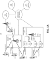
- FIG. 1A illustrates one embodiment of an example communications system 100 in which the methods and apparatuses described and claimed herein may be embodied.
- the example communications system 100 may include wireless transmit/receive units (WTRUs) 102a, 102b, 102c, and/or 102d (which generally or collectively may be referred to as WTRU 102), a radio access network (RAN) 103/104/105/103b/104b/105b, a core network 106/107/109, a public switched telephone network (PSTN) 108, the Internet 110, and other networks 112, though it will be appreciated that the disclosed embodiments contemplate any number of WTRUs, base stations, networks, and/or network elements.
- WTRUs wireless transmit/receive units
- RAN radio access network
- PSTN public switched telephone network
- Each of the WTRUs 102a, 102b, 102c, 102d, 102e may be any type of apparatus or device configured to operate and/or communicate in a wireless environment. Although each WTRU 102a, 102b, 102c, 102d, 102e is depicted in FIGs.
- each WTRU may comprise or be embodied in any type of apparatus or device configured to transmit and/or receive wireless signals, including, by way of example only, user equipment (UE), a mobile station, a fixed or mobile subscriber unit, a pager, a cellular telephone, a personal digital assistant (PDA), a smartphone, a laptop, a tablet, a netbook, a notebook computer, a personal computer, a wireless sensor, consumer electronics, a wearable device such as a smart watch or smart clothing, a medical or eHealth device, a robot, industrial equipment, a drone, a vehicle such as a car, truck, train, or airplane, and the like.
- UE user equipment
- PDA personal digital assistant
- smartphone a laptop, a tablet, a netbook, a notebook computer, a personal computer, a wireless sensor, consumer electronics, a wearable device such as a smart watch or smart clothing, a medical or eHealth device, a robot, industrial equipment, a drone, a vehicle such as a
- the communications system 100 may also include a base station 114a and a base station 114b.
- Base stations 114a may be any type of device configured to wirelessly interface with at least one of the WTRUs 102a, 102b, 102c to facilitate access to one or more communication networks, such as the core network 106/107/109, the Internet 110, and/or the other networks 112.
- Base stations 114b may be any type of device configured to wiredly and/or wirelessly interface with at least one of the RRHs (Remote Radio Heads) 118a, 118b and/or TRPs (Transmission and Reception Points) 119a, 119b to facilitate access to one or more communication networks, such as the core network 106/107/109, the Internet 110, and/or the other networks 112.
- RRHs 118a, 118b may be any type of device configured to wirelessly interface with at least one of the WTRU 102c, to facilitate access to one or more communication networks, such as the core network 106/107/109, the Internet 110, and/or the other networks 112.
- TRPs 119a, 119b may be any type of device configured to wirelessly interface with at least one of the WTRU 102d, to facilitate access to one or more communication networks, such as the core network 106/107/109, the Internet 110, and/or the other networks 112.
- the base stations 114a, 114b may be a base transceiver station (BTS), a Node-B, an eNode B, a Home Node B, a Home eNode B, a site controller, an access point (AP), a wireless router, and the like. While the base stations 114a, 114b are each depicted as a single element, it will be appreciated that the base stations 114a, 114b may include any number of interconnected base stations and/or network elements.
- the base station 114a may be part of the RAN 103/104/105, which may also include other base stations and/or network elements (not shown), such as a base station controller (BSC), a radio network controller (RNC), relay nodes, etc.
- the base station 114b may be part of the RAN 103b/104b/105b, which may also include other base stations and/or network elements (not shown), such as a base station controller (BSC), a radio network controller (RNC), relay nodes, etc.
- the base station 114a may be configured to transmit and/or receive wireless signals within a particular geographic region, which may be referred to as a cell (not shown).
- the base station 114b may be configured to transmit and/or receive wired and/or wireless signals within a particular geographic region, which may be referred to as a cell (not shown).
- the cell may further be divided into cell sectors.
- the cell associated with the base station 114a may be divided into three sectors.
- the base station 114a may include three transceivers, e.g., one for each sector of the cell.
- the base station 114a may employ multiple-input multiple output (MIMO) technology and, therefore, may utilize multiple transceivers for each sector of the cell.
- MIMO multiple-input multiple output
- the base stations 114a may communicate with one or more of the WTRUs 102a, 102b, 102c over an air interface 115/116/117, which may be any suitable wireless communication link (e.g., radio frequency (RF), microwave, infrared (IR), ultraviolet (UV), visible light, cmWave, mmWave, etc.).
- the air interface 115/116/117 may be established using any suitable radio access technology (RAT).
- RAT radio access technology
- the base stations 114b may communicate with one or more of the RRHs 118a, 118b and/or TRPs 119a, 119b over a wired or air interface 115b/116b/117b, which may be any suitable wired (e.g., cable, optical fiber, etc.) or wireless communication link (e.g., radio frequency (RF), microwave, infrared (IR), ultraviolet (UV), visible light, cmWave, mmWave, etc.).
- RF radio frequency
- IR infrared
- UV ultraviolet
- the air interface 115b/116b/117b may be established using any suitable radio access technology (RAT).
- RAT radio access technology
- the RRHs 118a, 118b and/or TRPs 119a, 119b may communicate with one or more of the WTRUs 102c, 102d over an air interface 115c/116c/117c, which may be any suitable wireless communication link (e.g., radio frequency (RF), microwave, infrared (IR), ultraviolet (UV), visible light, cmWave, mmWave, etc.).
- the air interface 115c/116c/117c may be established using any suitable radio access technology (RAT).
- RAT radio access technology
- the communications system 100 may be a multiple access system and may employ one or more channel access schemes, such as CDMA, TDMA, FDMA, OFDMA, SC-FDMA, and the like.
- the base station 114a in the RAN 103/104/105 and the WTRUs 102a, 102b, 102c, or RRHs 118a, 118b and TRPs 119a, 119b in the RAN 103b/104b/105b and the WTRUs 102c, 102d may implement a radio technology such as Universal Mobile Telecommunications System (UMTS) Terrestrial Radio Access (UTRA), which may establish the air interface 115/116/117 or 115c/116c/117c respectively using wideband CDMA (WCDMA).
- UMTS Universal Mobile Telecommunications System
- UTRA Universal Mobile Telecommunications System
- WCDMA wideband CDMA
- WCDMA may include communication protocols such as High-Speed Packet Access (HSPA) and/or Evolved HSPA (HSPA+).
- HSPA may include High-Speed Downlink Packet Access (HSDPA) and/or High-Speed Uplink Packet Access (HSUPA).
- HSPA High-Speed Packet Access
- HSDPA High-Speed Downlink Packet Access
- HSUPA High-Speed Uplink Packet Access
- the base station 114a and the WTRUs 102a, 102b, 102c, or RRHs 118a, 118b and TRPs 119a, 119b in the RAN 103b/104b/105b and the WTRUs 102c, 102d may implement a radio technology such as Evolved UMTS Terrestrial Radio Access (E-UTRA), which may establish the air interface 115/116/117 or 115c/116c/117c respectively using Long Term Evolution (LTE) and/or LTE-Advanced (LTE-A).
- E-UTRA Evolved UMTS Terrestrial Radio Access
- LTE Long Term Evolution
- LTE-A LTE-Advanced
- the air interface 115/116/117 may implement 3GPP NR technology.
- the base station 114a in the RAN 103/104/105 and the WTRUs 102a, 102b, 102c, or RRHs 118a, 118b and TRPs 119a, 119b in the RAN 103b/104b/105b and the WTRUs 102c, 102d may implement radio technologies such as IEEE 802.16 (e.g., Worldwide Interoperability for Microwave Access (WiMAX)), CDMA2000, CDMA2000 1X, CDMA2000 EV-DO, Interim Standard 2000 (IS-2000), Interim Standard 95 (IS-95), Interim Standard 856 (IS-856), Global System for Mobile communications (GSM), Enhanced Data rates for GSM Evolution (EDGE), GSM EDGE (GERAN), and the like.
- IEEE 802.16 e.g., Worldwide Interoperability for Microwave Access (WiMAX)
- CDMA2000, CDMA2000 1X, CDMA2000 EV-DO Interim Standard 2000 (IS-2000), Interim Standard 95 (
- the base station 114c in FIG. 1A may be a wireless router, Home Node B, Home eNode B, or access point, for example, and may utilize any suitable RAT for facilitating wireless connectivity in a localized area, such as a place of business, a home, a vehicle, a campus, and the like.
- the base station 114c and the WTRUs 102e may implement a radio technology such as IEEE 802.11 to establish a wireless local area network (WLAN).
- the base station 114c and the WTRUs 102d may implement a radio technology such as IEEE 802.15 to establish a wireless personal area network (WPAN).
- WLAN wireless local area network
- WPAN wireless personal area network
- the base station 114c and the WTRUs 102e may utilize a cellular-based RAT (e.g., WCDMA, CDMA2000, GSM, LTE, LTE-A, etc.) to establish a picocell or femtocell.
- a cellular-based RAT e.g., WCDMA, CDMA2000, GSM, LTE, LTE-A, etc.
- the base station 114b may have a direct connection to the Internet 110.
- the base station 114c may not be required to access the Internet 110 via the core network 106/107/109.
- the RAN 103/104/105 and/or RAN 103b/104b/105b may be in communication with the core network 106/107/109, which may be any type of network configured to provide voice, data, applications, and/or voice over internet protocol (VoIP) services to one or more of the WTRUs 102a, 102b, 102c, 102d.
- the core network 106/107/109 may provide call control, billing services, mobile location-based services, pre-paid calling, Internet connectivity, video distribution, etc., and/or perform high-level security functions, such as user authentication.
- the RAN 103/104/105 and/or RAN 103b/104b/105b and/or the core network 106/107/109 may be in direct or indirect communication with other RANs that employ the same RAT as the RAN 103/104/105 and/or RAN 103b/104b/105b or a different RAT.
- the core network 106/107/109 may also be in communication with another RAN (not shown) employing a GSM radio technology.
- the core network 106/107/109 may also serve as a gateway for the WTRUs 102a, 102b, 102c, 102d, 102e to access the PSTN 108, the Internet 110, and/or other networks 112.
- the PSTN 108 may include circuit-switched telephone networks that provide plain old telephone service (POTS).
- POTS plain old telephone service
- the Internet 110 may include a global system of interconnected computer networks and devices that use common communication protocols, such as the transmission control protocol (TCP), user datagram protocol (UDP) and the internet protocol (IP) in the TCP/IP internet protocol suite.
- the networks 112 may include wired or wireless communications networks owned and/or operated by other service providers.
- the networks 112 may include another core network connected to one or more RANs, which may employ the same RAT as the RAN 103/104/105 and/or RAN 103b/104b/105b or a different RAT.
- Some or all of the WTRUs 102a, 102b, 102c, 102d in the communications system 100 may include multi-mode capabilities, e.g., the WTRUs 102a, 102b, 102c, 102d, and 102e may include multiple transceivers for communicating with different wireless networks over different wireless links.
- the WTRU 102e shown in FIG. 1A may be configured to communicate with the base station 114a, which may employ a cellular-based radio technology, and with the base station 114c, which may employ an IEEE 802 radio technology.
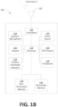
- FIG. 1B is a block diagram of an example apparatus or device configured for wireless communications in accordance with the embodiments illustrated herein, such as for example, a WTRU 102.
- the example WTRU 102 may include a processor 118, a transceiver 120, a transmit/receive element 122, a speaker/microphone 124, a keypad 126, a display/touchpad/indicators 128, non-removable memory 130, removable memory 132, a power source 134, a global positioning system (GPS) chipset 136, and other peripherals 138.
- GPS global positioning system
- the base stations 114a and 114b, and/or the nodes that base stations 114a and 114b may represent, such as but not limited to transceiver station (BTS), a Node-B, a site controller, an access point (AP), a home node-B, an evolved home node-B (eNodeB), a home evolved node-B (HeNB), a home evolved node-B gateway, and proxy nodes, among others, may include some or all of the elements depicted in FIG. 1B and described herein.
- BTS transceiver station
- Node-B a Node-B
- AP access point
- eNodeB evolved home node-B
- HeNB home evolved node-B gateway
- proxy nodes among others, may include some or all of the elements depicted in FIG. 1B and described herein.
- the processor 118 may be a general purpose processor, a special purpose processor, a conventional processor, a digital signal processor (DSP), a plurality of microprocessors, one or more microprocessors in association with a DSP core, a controller, a microcontroller, Application Specific Integrated Circuits (ASICs), Field Programmable Gate Array (FPGAs) circuits, any other type of integrated circuit (IC), a state machine, and the like.
- the processor 118 may perform signal coding, data processing, power control, input/output processing, and/or any other functionality that enables the WTRU 102 to operate in a wireless environment.
- the processor 118 may be coupled to the transceiver 120, which may be coupled to the transmit/receive element 122. While FIG. 1B depicts the processor 118 and the transceiver 120 as separate components, it will be appreciated that the processor 118 and the transceiver 120 may be integrated together in an electronic package or chip.
- the transmit/receive element 122 may be configured to transmit signals to, or receive signals from, a base station (e.g., the base station 114a) over the air interface 115/116/117.
- the transmit/receive element 122 may be an antenna configured to transmit and/or receive RF signals.
- the transmit/receive Although not shown in FIG. 1A , it will be appreciated that the RAN 103/104/105 and/or the core network 106/107/109 may be in direct or indirect communication with other RANs that employ the same RAT as the RAN 103/104/105 or a different RAT.
- the core network 106/107/109 may also be in communication with another RAN (not shown) employing a GSM radio technology.
- the core network 106/107/109 may also serve as a gateway for the WTRUs 102a, 102b, 102c, 102d to access the PSTN 108, the Internet 110, and/or other networks 112.
- the PSTN 108 may include circuit-switched telephone networks that provide plain old telephone service (POTS).
- POTS plain old telephone service
- the Internet 110 may include a global system of interconnected computer networks and devices that use common communication protocols, such as the transmission control protocol (TCP), user datagram protocol (UDP) and the internet protocol (IP) in the TCP/IP internet protocol suite.
- the networks 112 may include wired or wireless communications networks owned and/or operated by other service providers.
- the networks 112 may include another core network connected to one or more RANs, which may employ the same RAT as the RAN 103/104/105 or a different RAT.
- Some or all of the WTRUs 102a, 102b, 102c, 102d in the communications system 100 may include multi-mode capabilities, e.g., the WTRUs 102a, 102b, 102c, and 102d may include multiple transceivers for communicating with different wireless networks over different wireless links.
- the WTRU 102c shown in FIG. 1A may be configured to communicate with the base station 114a, which may employ a cellular-based radio technology, and with the base station 114b, which may employ an IEEE 802 radio technology.
- FIG. 1B is a block diagram of an example apparatus or device configured for wireless communications in accordance with the embodiments illustrated herein, such as for example, a WTRU 102.
- the example WTRU 102 may include a processor 118, a transceiver 120, a transmit/receive element 122, a speaker/microphone 124, a keypad 126, a display/touchpad/indicators 128, non-removable memory 130, removable memory 132, a power source 134, a global positioning system (GPS) chipset 136, and other peripherals 138.
- GPS global positioning system
- the base stations 114a and 114b, and/or the nodes that base stations 114a and 114b may represent, such as but not limited to transceiver station (BTS), a Node-B, a site controller, an access point (AP), a home node-B, an evolved home node-B (eNodeB), a home evolved node-B (HeNB), a home evolved node-B gateway, and proxy nodes, among others, may include some or all of the elements depicted in FIG. 1B and described herein.
- BTS transceiver station
- Node-B a Node-B
- AP access point
- eNodeB evolved home node-B
- HeNB home evolved node-B gateway
- proxy nodes among others, may include some or all of the elements depicted in FIG. 1B and described herein.
- the processor 118 may be a general purpose processor, a special purpose processor, a conventional processor, a digital signal processor (DSP), a plurality of microprocessors, one or more microprocessors in association with a DSP core, a controller, a microcontroller, Application Specific Integrated Circuits (ASICs), Field Programmable Gate Array (FPGAs) circuits, any other type of integrated circuit (IC), a state machine, and the like.
- the processor 118 may perform signal coding, data processing, power control, input/output processing, and/or any other functionality that enables the WTRU 102 to operate in a wireless environment.
- the processor 118 may be coupled to the transceiver 120, which may be coupled to the transmit/receive element 122. While FIG. 1B depicts the processor 118 and the transceiver 120 as separate components, it will be appreciated that the processor 118 and the transceiver 120 may be integrated together in an electronic package or chip.
- the transmit/receive element 122 may be configured to transmit signals to, or receive signals from, a base station (e.g., the base station 114a) over the air interface 115/116/117.
- a base station e.g., the base station 114a
- the transmit/receive element 122 may be an antenna configured to transmit and/or receive RF signals.
- the transmit/receive element 122 may be an emitter/detector configured to transmit and/or receive IR, UV, or visible light signals, for example.
- the transmit/receive element 122 may be configured to transmit and receive both RF and light signals. It will be appreciated that the transmit/receive element 122 may be configured to transmit and/or receive any combination of wireless signals.
- the WTRU 102 may include any number of transmit/receive elements 122. More specifically, the WTRU 102 may employ MIMO technology. Thus, in an embodiment, the WTRU 102 may include two or more transmit/receive elements 122 (e.g., multiple antennas) for transmitting and receiving wireless signals over the air interface 115/116/117.
- the WTRU 102 may include two or more transmit/receive elements 122 (e.g., multiple antennas) for transmitting and receiving wireless signals over the air interface 115/116/117.
- the transceiver 120 may be configured to modulate the signals that are to be transmitted by the transmit/receive element 122 and to demodulate the signals that are received by the transmit/receive element 122.
- the WTRU 102 may have multi-mode capabilities.
- the transceiver 120 may include multiple transceivers for enabling the WTRU 102 to communicate via multiple RATs, such as UTRA and IEEE 802.11, for example.
- the processor 118 of the WTRU 102 may be coupled to, and may receive user input data from, the speaker/microphone 124, the keypad 126, and/or the display/touchpad/indicators 128 (e.g., a liquid crystal display (LCD) display unit or organic light-emitting diode (OLED) display unit).
- the processor 118 may also output user data to the speaker/microphone 124, the keypad 126, and/or the display/touchpad/indicators 128.
- the processor 118 may access information from, and store data in, any type of suitable memory, such as the non-removable memory 130 and/or the removable memory 132.
- the non-removable memory 130 may include random-access memory (RAM), read-only memory (ROM), a hard disk, or any other type of memory storage device.
- the removable memory 132 may include a subscriber identity module (SIM) card, a memory stick, a secure digital (SD) memory card, and the like.
- SIM subscriber identity module
- SD secure digital
- the processor 118 may access information from, and store data in, memory that is not physically located on the WTRU 102, such as on a server or a home computer (not shown).
- the processor 118 may receive power from the power source 134, and may be configured to distribute and/or control the power to the other components in the WTRU 102.
- the power source 134 may be any suitable device for powering the WTRU 102.
- the power source 134 may include one or more dry cell batteries, solar cells, fuel cells, and the like.
- the processor 118 may also be coupled to the GPS chipset 136, which may be configured to provide location information (e.g., longitude and latitude) regarding the current location of the WTRU 102.
- location information e.g., longitude and latitude
- the WTRU 102 may receive location information over the air interface 115/116/117 from a base station (e.g., base stations 114a, 114b) and/or determine its location based on the timing of the signals being received from two or more nearby base stations. It will be appreciated that the WTRU 102 may acquire location information by way of any suitable location-determination method while remaining consistent with an embodiment.
- the processor 118 may further be coupled to other peripherals 138, which may include one or more software and/or hardware modules that provide additional features, functionality and/or wired or wireless connectivity.
- the peripherals 138 may include various sensors such as an accelerometer, biometrics (e.g., finger print) sensors, an e-compass, a satellite transceiver, a digital camera (for photographs or video), a universal serial bus (USB) port or other interconnect interfaces, a vibration device, a television transceiver, a hands free headset, a Bluetooth ® module, a frequency modulated (FM) radio unit, a digital music player, a media player, a video game player module, an Internet browser, and the like.
- biometrics e.g., finger print
- a satellite transceiver for photographs or video
- USB universal serial bus
- FM frequency modulated
- the WTRU 102 may be embodied in other apparatuses or devices, such as a sensor, consumer electronics, a wearable device such as a smart watch or smart clothing, a medical or eHealth device, a robot, industrial equipment, a drone, a vehicle such as a car, truck, train, or airplane.
- the WTRU 102 may connect to other components, modules, or systems of such apparatuses or devices via one or more interconnect interfaces, such as an interconnect interface that may comprise one of the peripherals 138.
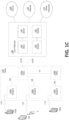
- FIG. 1C is a system diagram of the RAN 103 and the core network 106 according to an embodiment.
- the RAN 103 may employ a UTRA radio technology to communicate with the WTRUs 102a, 102b, and 102c over the air interface 115.
- the RAN 103 may also be in communication with the core network 106.
- the RAN 103 may include Node-Bs 140a, 140b, 140c, which may each include one or more transceivers for communicating with the WTRUs 102a, 102b, 102c over the air interface 115.
- the Node-Bs 140a, 140b, 140c may each be associated with a particular cell (not shown) within the RAN 103.
- the RAN 103 may also include RNCs 142a, 142b. It will be appreciated that the RAN 103 may include any number of Node-Bs and RNCs while remaining consistent with an embodiment.
- the Node-Bs 140a, 140b may be in communication with the RNC 142a. Additionally, the Node-B 140c may be in communication with the RNC 142b.
- the Node-Bs 140a, 140b, 140c may communicate with the respective RNCs 142a, 142b via an Iub interface.
- the RNCs 142a, 142b may be in communication with one another via an Iur interface.
- Each of the RNCs 142a, 142b may be configured to control the respective Node-Bs 140a, 140b, 140c to which it is connected.
- each of the RNCs 142a, 142b may be configured to carry out or support other functionality, such as outer loop power control, load control, admission control, packet scheduling, handover control, macro-diversity, security functions, data encryption, and the like.
- the core network 106 shown in FIG. 1C may include a media gateway (MGW) 144, a mobile switching center (MSC) 146, a serving GPRS support node (SGSN) 148, and/or a gateway GPRS support node (GGSN) 150. While each of the foregoing elements are depicted as part of the core network 106, it will be appreciated that any one of these elements may be owned and/or operated by an entity other than the core network operator.
- MGW media gateway
- MSC mobile switching center
- SGSN serving GPRS support node
- GGSN gateway GPRS support node
- the RNC 142a in the RAN 103 may be connected to the MSC 146 in the core network 106 via an IuCS interface.
- the MSC 146 may be connected to the MGW 144.
- the MSC 146 and the MGW 144 may provide the WTRUs 102a, 102b, 102c with access to circuit-switched networks, such as the PSTN 108, to facilitate communications between the WTRUs 102a, 102b, 102c and traditional land-line communications devices.
- the RNC 142a in the RAN 103 may also be connected to the SGSN 148 in the core network 106 via an IuPS interface.
- the SGSN 148 may be connected to the GGSN 150.
- the SGSN 148 and the GGSN 150 may provide the WTRUs 102a, 102b, 102c with access to packet-switched networks, such as the Internet 110, to facilitate communications between and the WTRUs 102a, 102b, 102c and IP-enabled devices.
- the core network 106 may also be connected to the networks 112, which may include other wired or wireless networks that are owned and/or operated by other service providers.
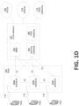
- FIG. 1D is a system diagram of the RAN 104 and the core network 107 according to an embodiment.
- the RAN 104 may employ an E-UTRA radio technology to communicate with the WTRUs 102a, 102b, and 102c over the air interface 116.
- the RAN 104 may also be in communication with the core network 107.
- the RAN 104 may include eNode-Bs 160a, 160b, 160c, though it will be appreciated that the RAN 104 may include any number of eNode-Bs while remaining consistent with an embodiment.
- the eNode-Bs 160a, 160b, 160c may each include one or more transceivers for communicating with the WTRUs 102a, 102b, 102c over the air interface 116.
- the eNode-Bs 160a, 160b, 160c may implement MIMO technology.
- the eNode-B 160a for example, may use multiple antennas to transmit wireless signals to, and receive wireless signals from, the WTRU 102a.
- Each of the eNode-Bs 160a, 160b, and 160c may be associated with a particular cell (not shown) and may be configured to handle radio resource management decisions, handover decisions, scheduling of users in the uplink and/or downlink, and the like. As shown in FIG. 1D , the eNode-Bs 160a, 160b, 160c may communicate with one another over an X2 interface.
- the core network 107 shown in FIG. 1D may include a mobility management gateway (MME) 162, a serving gateway 164, and a packet data network (PDN) gateway 166. While each of the foregoing elements are depicted as part of the core network 107, it will be appreciated that any one of these elements may be owned and/or operated by an entity other than the core network operator.
- MME mobility management gateway
- PDN packet data network
- the MME 162 may be connected to each of the eNode-Bs 160a, 160b, and 160c in the RAN 104 via an S1 interface and may serve as a control node.
- the MME 162 may be responsible for authenticating users of the WTRUs 102a, 102b, 102c, bearer activation/deactivation, selecting a particular serving gateway during an initial attach of the WTRUs 102a, 102b, 102c, and the like.
- the MME 162 may also provide a control plane function for switching between the RAN 104 and other RANs (not shown) that employ other radio technologies, such as GSM or WCDMA.
- the serving gateway 164 may be connected to each of the eNode-Bs 160a, 160b, and 160c in the RAN 104 via the S1 interface.
- the serving gateway 164 may generally route and forward user data packets to/from the WTRUs 102a, 102b, 102c.
- the serving gateway 164 may also perform other functions, such as anchoring user planes during inter-eNode B handovers, triggering paging when downlink data is available for the WTRUs 102a, 102b, 102c, managing and storing contexts of the WTRUs 102a, 102b, 102c, and the like.
- the serving gateway 164 may also be connected to the PDN gateway 166, which may provide the WTRUs 102a, 102b, 102c with access to packet-switched networks, such as the Internet 110, to facilitate communications between the WTRUs 102a, 102b, 102c and IP-enabled devices.
- the PDN gateway 166 may provide the WTRUs 102a, 102b, 102c with access to packet-switched networks, such as the Internet 110, to facilitate communications between the WTRUs 102a, 102b, 102c and IP-enabled devices.
- the core network 107 may facilitate communications with other networks.
- the core network 107 may provide the WTRUs 102a, 102b, 102c with access to circuit-switched networks, such as the PSTN 108, to facilitate communications between the WTRUs 102a, 102b, 102c and traditional land-line communications devices.
- the core network 107 may include, or may communicate with, an IP gateway (e.g., an IP multimedia subsystem (IMS) server) that serves as an interface between the core network 107 and the PSTN 108.
- IMS IP multimedia subsystem
- the core network 107 may provide the WTRUs 102a, 102b, 102c with access to the networks 112, which may include other wired or wireless networks that are owned and/or operated by other service providers.
- FIG. 1E is a system diagram of the RAN 105 and the core network 109 according to an embodiment.
- the RAN 105 may be an access service network (ASN) that employs IEEE 802.16 radio technology to communicate with the WTRUs 102a, 102b, and 102c over the air interface 117.
- ASN access service network
- the communication links between the different functional entities of the WTRUs 102a, 102b, 102c, the RAN 105, and the core network 109 may be defined as reference points.
- the RAN 105 may include base stations 180a, 180b, 180c, and an ASN gateway 182, though it will be appreciated that the RAN 105 may include any number of base stations and ASN gateways while remaining consistent with an embodiment.
- the base stations 180a, 180b, 180c may each be associated with a particular cell in the RAN 105 and may include one or more transceivers for communicating with the WTRUs 102a, 102b, 102c over the air interface 117.
- the base stations 180a, 180b, 180c may implement MIMO technology.
- the base station 180a for example, may use multiple antennas to transmit wireless signals to, and receive wireless signals from, the WTRU 102a.
- the base stations 180a, 180b, 180c may also provide mobility management functions, such as handoff triggering, tunnel establishment, radio resource management, traffic classification, quality of service (QoS) policy enforcement, and the like.
- the ASN gateway 182 may serve as a traffic aggregation point and may be responsible for paging, caching of subscriber profiles, routing to the core network 109, and the like.
- the air interface 117 between the WTRUs 102a, 102b, 102c and the RAN 105 may be defined as an R1 reference point that implements the IEEE 802.16 specification.
- each of the WTRUs 102a, 102b, and 102c may establish a logical interface (not shown) with the core network 109.
- the logical interface between the WTRUs 102a, 102b, 102c and the core network 109 may be defined as an R2 reference point, which may be used for authentication, authorization, IP host configuration management, and/or mobility management.
- the communication link between each of the base stations 180a, 180b, and 180c may be defined as an R8 reference point that includes protocols for facilitating WTRU handovers and the transfer of data between base stations.
- the communication link between the base stations 180a, 180b, 180c and the ASN gateway 182 may be defined as an R6 reference point.
- the R6 reference point may include protocols for facilitating mobility management based on mobility events associated with each of the WTRUs 102a, 102b, 102c.
- the RAN 105 may be connected to the core network 109.
- the communication link between the RAN 105 and the core network 109 may defined as an R3 reference point that includes protocols for facilitating data transfer and mobility management capabilities, for example.
- the core network 109 may include a mobile IP home agent (MIP-HA) 184, an authentication, authorization, accounting (AAA) server 186, and a gateway 188. While each of the foregoing elements are depicted as part of the core network 109, it will be appreciated that any one of these elements may be owned and/or operated by an entity other than the core network operator.
- MIP-HA mobile IP home agent
- AAA authentication, authorization, accounting
- the MIP-HA may be responsible for IP address management, and may enable the WTRUs 102a, 102b, and 102c to roam between different ASNs and/or different core networks.
- the MIP-HA 184 may provide the WTRUs 102a, 102b, 102c with access to packet-switched networks, such as the Internet 110, to facilitate communications between the WTRUs 102a, 102b, 102c and IP-enabled devices.
- the AAA server 186 may be responsible for user authentication and for supporting user services.
- the gateway 188 may facilitate interworking with other networks.
- the gateway 188 may provide the WTRUs 102a, 102b, 102c with access to circuit-switched networks, such as the PSTN 108, to facilitate communications between the WTRUs 102a, 102b, 102c and traditional land-line communications devices.
- the gateway 188 may provide the WTRUs 102a, 102b, 102c with access to the networks 112, which may include other wired or wireless networks that are owned and/or operated by other service providers.
- the RAN 105 may be connected to other ASNs and the core network 109 may be connected to other core networks.
- the communication link between the RAN 105 the other ASNs may be defined as an R4 reference point, which may include protocols for coordinating the mobility of the WTRUs 102a, 102b, 102c between the RAN 105 and the other ASNs.
- the communication link between the core network 109 and the other core networks may be defined as an R5 reference, which may include protocols for facilitating interworking between home core networks and visited core networks.
- the core network entities described herein and illustrated in FIGs. 1A , 1C , 1D , and 1E are identified by the names given to those entities in certain existing 3GPP specifications, but it is understood that in the future those entities and functionalities may be identified by other names and certain entities or functions may be combined in future specifications published by 3GPP, including future 3GPP NR specifications.
- the particular network entities and functionalities described and illustrated in FIGs. 1A , 1B , 1C , 1D , and 1E are provided by way of example only, and it is understood that the subject matter disclosed and claimed herein may be embodied or implemented in any similar communication system, whether presently defined or defined in the future.
- FIG. 1F is a block diagram of an exemplary computing system 90 in which one or more apparatuses of the communications networks illustrated in FIGs. 1A , 1C , 1D and 1E may be embodied, such as certain nodes or functional entities in the RAN 103/104/105, Core Network 106/107/109, PSTN 108, Internet 110, or Other Networks 112.
- Computing system 90 may comprise a computer or server and may be controlled primarily by computer readable instructions, which may be in the form of software, wherever, or by whatever means such software is stored or accessed. Such computer readable instructions may be executed within a processor 91, to cause computing system 90 to do work.
- the processor 91 may be a general purpose processor, a special purpose processor, a conventional processor, a digital signal processor (DSP), a plurality of microprocessors, one or more microprocessors in association with a DSP core, a controller, a microcontroller, Application Specific Integrated Circuits (ASICs), Field Programmable Gate Array (FPGAs) circuits, any other type of integrated circuit (IC), a state machine, and the like.
- the processor 91 may perform signal coding, data processing, power control, input/output processing, and/or any other functionality that enables the computing system 90 to operate in a communications network.
- Coprocessor 81 is an optional processor, distinct from main processor 91, that may perform additional functions or assist processor 91. Processor 91 and/or coprocessor 81 may receive, generate, and process data related to the methods and apparatuses disclosed herein.
- processor 91 fetches, decodes, and executes instructions, and transfers information to and from other resources via the computing system's main data-transfer path, system bus 80.
- system bus 80 Such a system bus connects the components in computing system 90 and defines the medium for data exchange.
- System bus 80 typically includes data lines for sending data, address lines for sending addresses, and control lines for sending interrupts and for operating the system bus.
- An example of such a system bus 80 is the PCI (Peripheral Component Interconnect) bus.
- RAM random access memory
- ROM read only memory
- Such memories include circuitry that allows information to be stored and retrieved.
- ROMs 93 generally contain stored data that cannot easily be modified. Data stored in RAM 82 can be read or changed by processor 91 or other hardware devices. Access to RAM 82 and/or ROM 93 may be controlled by memory controller 92.
- Memory controller 92 may provide an address translation function that translates virtual addresses into physical addresses as instructions are executed. Memory controller 92 may also provide a memory protection function that isolates processes within the system and isolates system processes from user processes. Thus, a program running in a first mode can access only memory mapped by its own process virtual address space; it cannot access memory within another process's virtual address space unless memory sharing between the processes has been set up.
- computing system 90 may contain peripherals controller 83 responsible for communicating instructions from processor 91 to peripherals, such as printer 94, keyboard 84, mouse 95, and disk drive 85.
- peripherals controller 83 responsible for communicating instructions from processor 91 to peripherals, such as printer 94, keyboard 84, mouse 95, and disk drive 85.
- Display 86 which is controlled by display controller 96, is used to display visual output generated by computing system 90. Such visual output may include text, graphics, animated graphics, and video. The visual output may be provided in the form of a graphical user interface (GUI). One example of the GUI is shown in FIG. 25.
- Display 86 may be implemented with a CRT-based video display, an LCD-based flat-panel display, gas plasma-based flat-panel display, or a touch-panel.
- Display controller 96 includes electronic components required to generate a video signal that is sent to display 86.
- computing system 90 may contain communication circuitry, such as for example a network adapter 97, that may be used to connect computing system 90 to an external communications network, such as the RAN 103/104/105, Core Network 106/107/109, PSTN 108, Internet 110, or Other Networks 112 of FIGs. 1A , 1B , 1C , 1D , and 1E , to enable the computing system 90 to communicate with other nodes or functional entities of those networks.
- the communication circuitry alone or in combination with the processor 91, may be used to perform the transmitting and receiving steps of certain apparatuses, nodes, or functional entities described herein.
- any or all of the apparatuses, systems, methods and processes described herein may be embodied in the form of computer executable instructions (e.g., program code) stored on a computer-readable storage medium which instructions, when executed by a processor, such as processors 118 or 91, cause the processor to perform and/or implement the systems, methods and processes described herein.
- a processor such as processors 118 or 91
- any of the steps, operations or functions described herein may be implemented in the form of such computer executable instructions, executing on the processor of an apparatus or computing system configured for wireless and/or wired network communications.
- Computer readable storage media include volatile and nonvolatile, removable and non-removable media implemented in any non-transitory (e.g., tangible or physical) method or technology for storage of information, but such computer readable storage media do not includes signals.
- Computer readable storage media include, but are not limited to, RAM, ROM, EEPROM, flash memory or other memory technology, CD-ROM, digital versatile disks (DVD) or other optical disk storage, magnetic cassettes, magnetic tape, magnetic disk storage or other magnetic storage devices, or any other tangible or physical medium which can be used to store the desired information and which can be accessed by a computing system.
- 3GPP TR 38.913 defines scenarios and requirements for NR technologies.
- KPIs Key Performance Indicators
- Table 2 Device KPI Description Requirement eMBB Peak data rate Peak data rate is the highest theoretical data rate which is the received data bits assuming error-free conditions assignable to a single mobile station, when all assignable radio resources for the corresponding link direction are utilized (i.e., excluding radio resources that are used for physical layer synchronization, reference signals or pilots, guard bands and guard times).
- 20Gbps for downlink and 10Gbps for uplink Mobility interruption time Mobility interruption time means the shortest time duration supported by the system during which a user terminal cannot exchange user plane packets with any base station during transitions.
- 0ms for intra-system mobility Data Plane Latency For eMBB value the evaluation needs to consider all typical delays associated with the transfer of the data packets in an efficient way (e.g. applicable procedural delay when resources are not pre-allocated, averaged HARQ retransmission delay, impacts of network architecture).
- 4ms for UL, and 4ms for DL URLLC Control Plane Latency Control plane latency refers to the time to move from a battery efficient state (e.g., IDLE) to start of continuous data transfer (e.g., ACTIVE).
- 10 ms Data Plane Latency For URLLC the target for user plane latency for UL and DL.
- the latency should also be low enough to support the use of the next generation access technologies as a wireless transport technology that can be used within the next generation access architecture.
- 0.5 ms Reliability Reliability can be evaluated by the success probability of transmitting X bytes (1) within 1 ms, which is the time it takes to deliver a small data packet from the radio protocol layer 2/3 SDU ingress point to the radio protocol layer 2/3 SDU point of the radio interface, at a certain channel quality (e.g., coverage-edge). 1-10-5 within 1 ms.
- Specific value for X is FFS.
- MCL Maximum coupling loss
- UE Battery Life User Equipment
- UE battery life in extreme coverage shall be based on the activity of mobile originated data transfer consisting of [200 bytes] Uplink (UL) per day followed by [20 bytes] Downlink (DL) from Maximum Coupling Loss (MCL) of dB, assuming a stored energy capacity of [5Wh].
- Connection Density refers to total number of devices fulfilling specific Quality of Service (QoS) per unit area (per km2).
- QoS definition should take into account the amount of data or access request generated within a time t_gen that can be sent or received within a given time, t_sendrx, with x% probability. 106 devices/km2
- the analog beam of a subarray can be steered toward a single direction at the time resolution of an OFDM symbol or at any appropriate time interval unit defined for beam steering across different serving areas within the cell.
- the number of subarrays determines the number of beam directions and the corresponding coverage on each OFDM symbol or time interval unit defined for the purpose of beams steering.
- the provision of multiple narrow coverage beams has been called "beam sweeping.” This concept is illustrated in FIG. 2 where the coverage of a sector level cell is achieved with sectors beams and multiple high gain narrow beams.
- multiple transmissions in the time domain with narrow coverage beams steered to cover different serving areas is essential to cover the whole coverage areas within a serving cell in NR.
- Beam pairing is used to select the best beam pair between a UE and its serving cell.
- the best beam pair can be used for control signaling or data transmission.
- a beam pair will consist of UE RX beam and gNB TX beam.
- a beam pair will consist of UE TX beam and gNB RX beam.
- Beam training is used for beam refinement. For example, a coarser sector beamforming may be applied during the beam sweeping and sector beam pairing procedure as illustrated in FIG. 2 . Beam training may then follow where the antenna weights vector are refined. And, this can be followed by the pairing of high gain narrow beams between the UE and gNB.
- two specially designed physical signals are broadcasted in each cell. These signals include the Primary Synchronization Signal (PSS) and the Secondary Synchronization Signal (SSS).
- PSS Primary Synchronization Signal
- SSS Secondary Synchronization Signal
- the detection of these two signals not only enables time and frequency synchronization, but also provides the UE with the physical layer identity of the cell and the cyclic prefix length.
- the UE proceeds to decode the Physical Broadcast Channel (PBCH) including critical system information such as system bandwidth, PHICH information and SFN.
- PBCH Physical Broadcast Channel
- the initial access signal includes DL synchronization channels, i.e., PSS/SSS and PBCH channel.
- a SS beam sweeping block is defined as a beam sweeping time unit for broadcasting PSS/SSS and PBCH.
- Each sweeping block may include one or more CP-OFDM symbols.
- Multiple blocks can form a beam sweeping burst.
- the length of a SS sweeping burst refers to the number of beam sweeping blocks in a burst. For example, if a beam sweeping burst length is equal to M, then there are M sweeping blocks in a burst.
- the DL beam-sweeping burst may periodically transmit at a period ' T'.
- This periodic T may be varied with different applications including URLLC, mMTC or eMBB services.
- T may also be varied with different frequency bands (or frequency ranges), numerology, and traffic/mobility profile of UE.
- the SS burst design can be varied with FDD, TDD, flexible subframe and numerology. If DL and UL transmissions occur at different frequency bands, i.e., FDD, the SS burst design can be across contiguous subframes without reserving UL transmissions. Hence, it can accommodate more SS blocks in a subframe than TDD. However, DL symbols in a slot or subframe may be reserved for gcPDCCH or UE-specific PDCCH transmissions. Therefore, non-contiguous SS bursts between continuous subframes can be supported in FDD.
- UL subframe transmissions may be reserved in a radio frame.
- the SS burst design has to support non-contiguous SS bursts between continuous subframes as well.
- the SS burst design in TDD also supports a various number of DL-UL subframes in a radio frames. For flexible subframe structures, it supports DL and UL transmission symbols in a subframe. Hence, SS burst designs can support a non-contiguous SS burst block.
- the UE after the UE successfully acquires the timing and frequency information from the PSS and SSS, and obtains the MIB/SIB in PBCH, the UE will start to perform Tx beam sweeping and DL Tx beam feedback.
- the uplink channels used by the UE for Tx beam sweeping and DL Tx beam feedback should be implicitly signaled/mapped from the acquired PSS/SSS (beam ID) and/or PBCH direct signaling.
- NR-PRACH is one example of such a UL channel.
- the PRACH illustrates the mapping/signaling.
- the PRACH resources used for Tx sweeping at an initial access stage may be fixed per frequency band or semi-statically configured by the gNB.
- PRACH resource information needs to be signaled in MIB or essential SIB (such as SIB1, SIB2 in LTE).
- MIB can be transmitted on PBCH and essential SIB can be transmitted on the secondary PBCH (denoted as SPBCH).
- one set of PRACH resources (in terms of time and frequency) is exclusively configured/mapped for each SS block (corresponding to one beam swept in the DL for initial access). All preambles configured in a PRACH signaled MIB/essential SIB (transmitted by PBCH or SPBCH) can be used for UEs that successfully acquire this beam in PSS/SSS.
- one set of PRACH resources is exclusively configured/mapped for a group of SS blocks (corresponding to several beams swept in the DL for initial access).
- the group can be a SS block transmitted in the same sub-frame. Any UE that successfully acquires a beam swept in this group of SS blocks can transmit on this set of PRACH resources.
- a subset of PRACH preambles are mapped for each SS block (corresponding to one beam swept in the DL).
- a UE that successfully acquires a beam in the SS block can transmit PRACH using one of the preambles in the subset mapped to the SS block.
- Subsets of preambles for different SS blocks are non-overlapping.
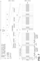
- FIG. 6 An example of UE uplink channels performing beam sweeping and DL Tx beam feedback to acquire the SS block in a FDD frame structure is illustrated in FIG. 6 .
- the following UE procedures are performed for beamforming based initial access.
- the UE performs the following steps: (i) Cross-correlate received signal with the Q possible PSS sequences, where Q is the maximum number of PSS sequences that can be supported; (ii) Store the cross-correlate result into various accumulation buffers according to the various PSS broadcast periodicity, respectively; and (iii) choose the strongest peak from the accumulation buffers; and (iv) obtain the corresponding partial cell ID (say, N ID 1 ) with its corresponding root sequence u .
- the time relative position of the correlation peak gives the time offset to the waveform symbol to begin SSS detection.
- the UE performs the following steps: (i) Cross-correlate received signal with the P possible SSS sequences; (ii) Store the cross-correlate result into various accumulation buffers according to the various SSS broadcast periodic, respectively; (iii) choose the strongest peak and obtain the corresponding partial cell ID (say, N ID 1 ); and (iv) Calculate cell ID N ID cell using N ID 1 and N ID 2 .
- the UE may obtain the beam ID either from the SS or from beam reference signals (BRS).
- the UE can understand which DL beam sweeping block is detected.
- the US is also able to calculate the timing offset from the detected beam sweeping block and the DL sweeping subframe.
- the UE can determine whether the beam (identified by the beam ID) is gNB's best DL Tx beam for the UE.
- the UE after the UE successfully detects SS (PSS/SSS) and acquires timing and frequency, it will obtain the timing information of the next PBCH.
- the evaluated information includes and is not limited to: (a) Timing of acquired SS (PSS/SSS) symbols (within the sub-frame); (b) Fixed timing of between SS (PSS/SSS) symbols and PBCH symbols; and (c) Periodicity of SS burst, periodicity of SS (PSS/SSS) symbols and periodicity of PBCH.
- the UE may need to perform blind detection to decode PBCH.
- the PBCH contains the MIB information elements such as DL Bandwidth and SFN (partial bits).
- the PBCH may also carry other information such as scheduling of SPBCH or information of UL channels (for example, PRACH) that can be used by the UE to perform its UL Tx beam sweeping and feedback of DL Tx beam acquired in SS.
- the UE may detect the SPBCH by obtaining the timing of the next PBCH according to the following information: (a)Timing of acquired SS (PSS/SSS) symbols (within the sub-frame); and (b) Fixed timing between SS (PSS/SSS) symbols, PBCH symbols and SPBCH symbols; (c) Periodicity of SS burst, periodicity of SS (PSS/SSS) symbols, periodicity of PBCH, and periodicity of SPBCH. Depending on the relative periodicities of SS (PSS/SSS) symbols, PBCH and SPBCH and the timing resolution of SFN carried in PBCH, the UE may perform blind detection to decode SPBCH.
- the SPBCH includes essential SIB information for the UE to further access the networks.
- Such information may include and is not limited to information of UL channels (for example, PRACH) that can be used by the UE to perform its UL Tx beam sweeping and feedback of DL Tx beam acquired in SS.
- UL channels for example, PRACH
- PRACH is employed to illustrate the proposed solutions assuming gNB and UE's UL and DL beamforming are reciprocal.
- the UE After the UE has successfully acquired SS, PBCH and SPBCH, it can obtain the following information based on implicit signaling/mapping of SS (PSS/SS), beam ID, and scheduling and PRACH information from PBCH and/or SPBCH: (i) The set of PRACH resources (in terms of time and frequency) for it to use in Tx beam sweeping and feedback of DL Tx beam; and (ii) The set of PRACH preambles for it to use (determined/mapped by the beam ID it acquired).
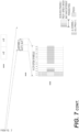
- FIG. 7 provides an exemplary illustration of a UE uplink channel to perform beam sweeping and DL Tx beam feedback linked to acquire a SS block in a flexible frame structure.
- the following procedures are performed for beam link pairing at initial access.
- the UE performs its Tx beam sweeping and feedback of DL Tx beam using PRACH preambles on the determined PRACH resources according to PRACH resources and preamble mapping rules. In this way, the feedback of the DL Tx beam for this UE is implicitly signaled by its PRACH transmission.
- the UE will transmit a series of PRACH preambles sweeping through a set of potential UL Tx beams (or all Tx beams).
- a series of PRACH transmission instances symbol, mini-slot, slot or subframe
- TS UL Tx Sweeping
- the PRACH used for UL Tx beam sweeping at the initial access stage consists of two parts - the preamble part and the subsequent message part.
- the UL Tx beam ID is explicitly signaled on the message part.
- the RA-RNTI can have the same formula as in LTE but with extended parameter ranges.
- f_id is the index of the specified PRACH within that PRACH transmission instance, in ascending order of frequency domain (0 ⁇ f_id ⁇ max_PRACH_resources_frequency_index).
- implicit signaling can be achieved by UE maintaining a record of preamble transmitted and beam used on each PRACH transmission during its UL Tx beam sweeping. That is, the UE records the database ⁇ Preamble Index, UL Beam ID, t_id, f_id ⁇ of each beam sweeping using PRACH.
- the method also needs to re-define the RA-RNTI as a function of t_id, f_id and beam ID, where t_id is the index of the first PRACH transmission instance (could be a symbol, a slot, a mini-slot or subframe) of the specified PRACH resources set (0 ⁇ t_id ⁇ max_PRACH_resources_time_index).
- f_id is the index of the specified PRACH within that PRACH transmission instance, in ascending order of frequency domain (0 ⁇ f_id ⁇ max_PRACH_resources_frequency_index).
- the gNB may detect several RACH preambles transmitted by the UE at different PRACH transmission instances within a TS burst. Unlike other RACH procedures where a Random Access Response (RAR) is generated for each detected RACH preamble, in UE initial access Tx beam sweeping, the gNB will pick the best preamble (and corresponding beam) within the TS burst and generate only one RAR for it.
- the criteria of picking the best preamble (and corresponding beam) includes and not limited to selecting the peak received power and SINR.
- the UE monitors the DL on the same DL Tx beam that it acquired during SS (PSS/SSS) detection for (RARs).
- the UE monitors the NR-PDCCH for RARs identified with RA-RNTIs corresponding to UE's PRACH transmission.
- the length of the RAR window will be selected to be long enough to cover the TS burst plus some margin.
- the RAR includes an UL grant.
- the RAR may also include the UE's UL Tx Beam ID feedback. If explicit signaling of the beam ID (method 1) is used in Step 1 of RACH procedures, then RAR will carry UE's UL Tx Beam ID feedback explicitly. If UE's preamble transmission does not explicitly carry its UL Tx beam ID (used in UL Tx beam sweeping), then gNB will use the re-defined RA-RNTI. Either way, the beam link pair (BPL) between the UE and gNB at the initial access is established at this step.
- BPL beam link pair
- Step 3 of this embodiment upon receiving a valid RAR with matched RA-RNTI, the UE will transmit the Msg3 (carrying a RRCConnectionRequest or similar message) according to the UL grant received in the RAR.
- the BPL determined in Step 2 should be used for beamforming transmission in Step 3.
- the gNB may perform contention resolution if multiple UEs transmit the same Msg3 in step 3.
- the BPL determined in Step 2 should be used for beamforming transmission in Step 4 as well.
- the UE is able to have the following configurations of channel and RS resources:
- the network can allocate and configure multiple sets of CSI-RS for the UE to perform (periodic or aperiodic) a beam link pairing maintenance operation.
- This may include a CSI-RS configuration for a UE (i.e., UE-specific) or for a group of UEs (i.e., group-common).
- the network will configure NR-PUCCHs for the UE or the group of UEs to transmit their beam report feedback.
- the UE will measure the configured CSI-RS and transmit the beam report feedback to the gNB according the feedback configuration (aperiodic, periodic or event-triggered).
- the UE For an event-triggered beam report feedback, one criteria is that the UE measure the current BPL quality. This is at least based upon the DM-RS in its received NR-PDCCH, NR-PDSCH. If it is below a predefined threshold, it will report the monitored beam report/quality to the gNB.
- the beam report format can be the best beam or Q best beams.
- the feedback information can include beam ID and quantized RSRP or SINR (optional).
- the gNB will compare the beam report with a current DL Tx beam used for the UE and decide whether to switch beams for DL. If the gNB decides to switch a DL Tx beam, it will transmit a special NR-PDCCH which contains an UL grant and allocates UL channels for the UE to perform UL Tx beam sweeping and a "beam switching command/indicator.” The UE will start UL Tx beam sweeping on the allocated UL channels. After the gNB selects the UE's best UL Tx beam and feedbacks it to the UE, a new BPL is determined and will be used in subsequent control and data transmissions between the UE and the gNB.
- the configured (group) CSI-RS can be used for group common PDCCH DMRS to save RS overhead.
- the UE feedback reporting cycle can operate with the connected-mode DRX cycle.
- the BQI (Beam Quality Indicator) mask protocol information element (IE) is introduced. This IE BQI-mask limits beam quality reports to the 'on' duration period of the DRX cycle. If the IE BQI-mask is not setup by RRC, the BQIs and beam IDs (BID) on NR-PUCCH are not reported when inactive. Otherwise the UE sends BQIs and BIDs on PUCCH only if onDurationTimer is running.
- the UE can perform beam measurement based on configured CSI-RS while onDurationTimer is running and send feedback via NR-PUCCH to gNB.
- the gNB receives the feedback of beam IDs from the UE, the gNB will compare the beam report with the current DL Tx beam used for the UE and decide whether to switch DL beam. If the gNB decides to switch DL Tx beam, it will transmit a special NR-PDCCH to indicate "beam switching command/indicator" and whether it needs to perform UL Tx beam sweeping.
- the UE After beam switching, if the UE is able to successfully decode the NR-PDCCH and/or NR-PDSCH, the UE can assume a new BPL has been established. Otherwise, if UE is able to decode NR-PDCCH but fails to decode NR-PDSCH, the UE might need to feedback A/N with BQIs and BIDs to gNB in NR-PUCCH. If there are no reserved NR-PUCCH resources, the UE can use NR-PRACH for UE feedback. If UE is unable to decode PDCCH, the UE might be able to trigger the link-failure procedure for the beam recovery.
- the gNB configures five training beams for a UE via CSI-RS or beam training RS.
- the UE can feedback the beam IDs (i.e., beam ID 1 to 5) and beam quality indicator to gNB via NR-PUCCH.
- the reporting timing of the beam ID and beam quality can be regularized by a timer.
- the gNB can send the beam switching command to indicate the UE is switching to a new beam for the next NR-PDSCH reception.
- the beam paring link (BPL) switching time can be defined to span from the time the NR-PUCCH carries the beam ID to the next NR-PDCCH carrying beam switching command.
- ⁇ bpl DL beam pair gain ⁇ UL beam pair gain .
- TPC 1" for increasing power and “-1" for decreasing power, "0" for no change, and ⁇ adj is the power adjustment either preconfigured, indicated in SI, or signaled to UE via RRC, MAC CE or DL DCI.
- FIG. 9 exemplarily illustrates a decision tree for estimating the Beam Pair Link Gain Difference (BPLGD) ⁇ bpl .
- BPLGD Beam Pair Link Gain Difference
- step 901 a calculation of the Beam Pair Link Gain Difference ⁇ bpl is based upon the selected beam pair during DL and/or UL beam training/pairing which is based on the measurements on the specific reference signal carried on the selected beam pair.
- step 902 an update of the UL transmit power calculation with ⁇ bpl is performed.
- a query is made for beam adjustment/recovering/switching. If No, the decision tree proceeds to an instance between steps 902 and 903. If Yes, the decision tree proceeds to step 904.
- Step 904 recalculates the Beam Pair Link Gain Difference ⁇ bpl of the adjusted or new beam pair from beam recovering or switching if there is no calibrated ⁇ bpl available for the adjusted or new beam pair.
- step 905 an update is made to the UL transmit power calculation for the adjusted or switched new beam pair with the ⁇ bpl related to the adjusted or new beam pair calculated or stored.
- FIGs. 10A /B and 11A/B illustrate detailed examples of estimating the beam pair link gain difference ⁇ bpl . Specifically, FIGs. 10A-10B estimate beam pair link gain difference during downlink beam training or pairing.
- DL_RS DL reference signal
- RSRP Reference Signal Received Power
- RSSI Received Signal Strength Indicator
- QI Channel Quality Indicator
- the UE reports the best beam DLTX_m to the TRP or gNB.
- the TRP or gNB calculates the UL path loss or UL transmit power adjustment based on the measurement of the received reference signal, e.g., RSRP of UL-RS such as sound reference signal (SRS) on UL.
- the UE may make adjustment with the Beam Pair Link Gain ⁇ bpl to its UL power control based on the path loss estimation with DL_RS_m, as well as L ULpath (calculated UL path loss), U Ladj (UL power control adjustment), or TPC (UL power control command, i.e. increasing or decreasing the UL power) feedback from the TRP or gNB.
- This ⁇ bpl is related to the selected DL_RS_M and the beam pair selected and can be used hereafter for adjust the UL transmit power for the associated beam pair.
- the UE reports the best beam pair DLTXRX_m to the TRP or gNB.
- the TRP or gNB calculates the UL path loss or UL transmit power adjustment based on the measurement of the received reference signal, e.g., RSRP of UL-RS such as SRS on UL.
- the UE receives a confirmed beam pair DLTXRX_m user a finer beam DLTX_m.
- the UE fine tunes the DLRx_m . In this step, the UE performs DL measurements.
- ⁇ bpl for the beam pair DLTXRX_m based on the measured L DLpath and received L ULpath /L adj /TPC.
- the UE fine tunes the DLRX_m and adjusts the UL transmit power accordingly.
- the UE starts the UL fine beam training.
- the ⁇ bpl is related to the selected DL_RS_M and the beam pair selected and can be used hereafter for adjust the UL transmit power for the associated beam pair.
- FIGs. 11A and 11B as a whole estimate beam pair link gain difference during uplink beam training or pairing.
- a UE sends UL beams with the initial power setting related to the UL_RS_n , such as SRS (n), carried on ULTx_n .
- the UE may make an adjustment with the Beam Pair Link Gain ⁇ bpl to its UL power control based on the path loss estimation with DL_RS_n carried on selected best beam ULTx_n, as well as L ULpath (calculated UL path loss), U Ladj (UL power control adjustment), or TPC (UL power control command, i.e. increasing or decreasing the UL power) feedback from the TRP or gNB.
- L ULpath calculated UL path loss
- U Ladj UL power control adjustment
- TPC UL power control command, i.e. increasing or decreasing the UL power
- the UE confirms the best beam ULTx_n and starts UL Rx selection with ULTx_n .
- the ⁇ bpl is related to the selected DL_RS_n and the beam pair selected and can be used hereafter for adjust the UL transmit power for the associated beam pair.
- the UE receives a report of the best beam pair ULTxRX_n.
- the UE fine tunes the ULTx_n .
- the UE performs DL measurements. It recalculates ⁇ bpl for the beam pair based on the measured L DLpath and received L ULpath /L adj /TPC.
- the UE fine tunes the ULTx_n and decides channel reciprocity.
- the UE confirms the beam pair ULTxRx_n using finer beam ULTx_n.
- the ⁇ bpl is related to the selected DL_RS_n and the beam pair selected and can be used hereafter for adjust the UL transmit power for the associated beam pair.
- FIG. 12 provides an exemplary user GUI for beam pair link measurements.
- the beam pair link measurements may be displayed in either text and/or graph form. This may be used to help a user to operate the handheld device properly and avoid unnecessary blockage at very high frequencies, such as at the mmWave frequency band.
- any or all of the systems, methods and processes described herein may be embodied in the form of computer executable instructions, e.g ., program code, stored on a computer-readable storage medium which instructions, when executed by a machine, such as a computer, server, M2M terminal device, M2M gateway device, transit device or the like, perform and/or implement the systems, methods and processes described herein.
- a machine such as a computer, server, M2M terminal device, M2M gateway device, transit device or the like
- any of the steps, operations or functions described above may be implemented in the form of such computer executable instructions.
- Computer readable storage media includes volatile and nonvolatile, removable and non-removable media implemented in any method or technology for storage of information, but such computer readable storage media do not includes signals.
- Computer readable storage media include, but are not limited to, RAM, ROM, EEPROM, flash memory or other memory technology, CD ROM, digital versatile disks (DVD) or other optical disk storage, magnetic cassettes, magnetic tape, magnetic disk storage or other magnetic storage devices, or any other physical medium which can be used to store the desired information and which can be accessed by a computer.
- a non-transitory computer-readable or executable storage medium for storing computer-readable or executable instructions.
- the medium may include one or more computer-executable instructions such as disclosed above in the plural call flows.
- the computer executable instructions may be stored in a memory and executed by a processor disclosed above in FIGs. 1C and 1F , and employed in devices including a node such as for example, end-user equipment.
- the UE as shown for example in FIGs. 1B and 1E is configured to perform the instructions of beam link pairing the apparatus to the router in new radio.
- the instructions may include: (i) transmitting physical random access channel (PRACH) preambles through a set of uplink transmission beams in a subframe; (ii) signaling a beam ID of the set of uplink transmission beams; (iii) monitoring a physical downlink control channel (PDCCH) for a random access response (RAR) including a random access radio network temporary identifier (RA-RNTI); and (iv) determining the RA-RNTI corresponds to the transmitted PRACH preambles.
- PRACH physical random access channel
- PDCCH physical downlink control channel
- RAR random access response
- RA-RNTI random access radio network temporary identifier
- the UE as shown for example in FIGs. 1B and 1E is configured to perform the instructions of beam link adjustments in the new radio.
- the instructions may include: (i) detecting downlink transmission beams transmitted from a gNB; (ii) performing downlink measurements with downlink reference signals on the detected downlink transmission beams; (iii) selecting an first downlink transmission beam based on the measurement; (iv) calculating a downlink path loss using a downlink reference signal of the first downlink transmission beam; (v) estimating an initial uplink transmit power based on the calculated downlink path loss; and vi) transmitting, to the gNB, an indication of the first downlink transmission beam with the estimated initial uplink transmit power.
- the UE as shown for example in FIGs. 1B and 1E is configured to perform the instructions of beam link adjustments in the new radio.
- the instructions may include: (i) sending, to the gNB, uplink transmission beams via uplink transmission beam sweeping with an initial uplink transmit power; (ii) receiving, from the gNB, an indication of a first uplink transmission beam from the sent uplink transmission beams, and an uplink path loss or uplink transmit power adjustment information; (iii) calculating a beam pair link gain difference based on a downlink path loss and the received uplink path loss or uplink transmit power adjustment information; and (iv) adjusting the initial uplink transmit power based upon the calculation
Landscapes
- Engineering & Computer Science (AREA)
- Signal Processing (AREA)
- Computer Networks & Wireless Communication (AREA)
- Mobile Radio Communication Systems (AREA)
Abstract
Description
- This application claims the benefit of priority of
U.S. Provisional application no. 62/475,744 filed March 23, 2017 - The present application is directed to apparatuses and methods for beam training and initial access in new radio
- New radio (NR) is the next evolutionary step from 3G and 4G wireless networks. At its core, NR intends to make wireless broadband performance substantially similar to that of wirelines. NR is also working on efficiently connecting Internet of Things (IoT) devices for reliable and safe communications.
- NR supports both low frequency NR (LF-NR), i.e.,
sub 6 GHz, and high frequency NR (HF-NR), i.e., above 6 GHz deployment. In LF-NR, a single wider beam may be sufficient for coverage. To the contrary, a single wider beam may be insufficient for coverage in HF-NR. This is attributed to significant attenuation at very high frequency. As a result, multiple narrow beams are preferred for enhancing coverage in HF-NR. - This summary is provided to introduce a selection of concepts in a simplified form that are further described below in the Detailed Description. This Summary is not intended to limit the scope of the claimed subject matter.
- One aspect of the disclosure is directed to an apparatus in new radio. The apparatus includes a non-transitory memory including instructions stored thereon for beam link pairing the apparatus to a router in the new radio. The apparatus also includes a processor, operably coupled to the non-transitory memory, capable of executing the instructions of transmitting physical random access channel (PRACH) preambles through a set of uplink transmission beams in a subframe. The processor is also capable of executing the instructions of signaling a beam ID of the set of uplink transmission beams. The processor is further capable of executing the instructions of monitoring a physical downlink control channel (PDCCH) for a random access response (RAR) including a random access radio network temporary identifier (RA-RNTI). The processor is even further capable of executing the instructions of determining the RA-RNTI corresponds to the transmitted PRACH preambles.
- Another aspect of the disclosure is directed to an apparatus. The apparatus includes a non-transitory memory including instructions stored thereon for beam link adjustments in the new radio. The apparatus also includes a processor, operably coupled to the non-transitory memory, capable of executing the instructions of detecting downlink transmission beams transmitted from gNB. The processor is also capable of executing the instructions of performing downlink measurements for the detected downlink transmission beam. The processor is further capable of executing the instructions of selecting a first downlink transmission beam based on the measurement. The processor is even further capable of executing the instructions of calculating a downlink path loss using a downlink reference signal of the first downlink transmission beam. The processor is even further capable of executing the instructions of estimating an initial uplink transmit power based on the calculated downlink path loss. Still further, the processor is capable of executing the instructions of transmitting, to the gNB, an indication of the first downlink transmission beam with the estimated initial uplink transmit power.
- Yet another aspect of the disclosure is directed to an apparatus in new radio. The apparatus includes a non-transitory memory including instructions stored thereon for beam link adjustments in the new radio. The apparatus also includes a processor, operably coupled to the non-transitory memory, capable of executing the instructions of sending, to a gNB, uplink transmission beams via uplink transmission beam sweeping with an initial uplink transmit power. The processor is also capable of executing the instructions of receiving, from the gNB, an indication of a first uplink transmission beam from the sent uplink transmission beams, and an uplink path loss or uplink transmit power adjustment information. The processor is further capable of executing the instructions of calculating a beam pair link gain difference based on a downlink path loss and the received uplink path loss or uplink transmit power adjustment information. The processor is even further capable of executing the instructions of adjusting the initial uplink transmit power based upon the calculation.
- There has thus been outlined, rather broadly, certain embodiments of the invention in order that the detailed description thereof may be better understood, and in order that the present contribution to the art may be better appreciated.
- In order to facilitate a more robust understanding of the application, reference is now made to the accompanying drawings, in which like elements are referenced with like numerals. These drawings should not be construed to limit the application and are intended only to be illustrative.
-
FIG. 1A illustrates an exemplary communications system according to an embodiment of the application. -
FIG. 1B illustrates an exemplary apparatus configured for wireless communication according to an embodiment of the application. -
FIG. 1C illustrates a system diagram of a radio access network and a core network according to an embodiment of the application. -
FIG. 1D illustrates a system diagram of a radio access network and a core network according to another embodiment of the application. -
FIG. 1E illustrates a system diagram of a radio access network and a core network according to yet another embodiment of the application. -
FIG. 1F illustrates a block diagram of an exemplary computing system in communication with one or more networks previously shown inFIGs. 1A ,1C ,1D and1E according to an embodiment of the application. -
FIG. 2 illustrates cell coverage with sector beams and multiple, high-gain narrow beams. -
FIG. 3 illustrates a LTE frame structure with a primary synchronous sequence (PSS), a secondary synchronous sequence (SSS), and physical broadcast channel (PBCH) allocations. -
FIG. 4 illustrates an example of cell and sector sweeping. -
FIGs. 5A and 5B respectively illustrate NR systems supporting single and multi-beam systems. -
FIG. 6 illustrates a user equipment uplink (UL) channel to perform beam sweeping and downlink (DL) transmission beam feedback linked to acquire a SS block in the FDD frame structure. -
FIG. 7 illustrates a user equipment UL channel to perform beam sweeping and DL transmission beam feedback linked to the acquired SS block in a flexible frame structure. -
FIG. 8 illustrates a configured CSI-RS that can be used for BPL. -
FIG. 9 illustrates an estimation of a beam pair link gain difference. -
FIGs. 10A and10B illustrate an estimation of a beam pair link gain difference during downlink beam training or pairing. -
FIGs. 11A and11B illustrate an estimation of a beam pair link gain difference during uplink beam training or pairing. -
FIG. 12 illustrates a graphical user interface for a beam pair link measurement. - A detailed description of the illustrative embodiment will be discussed in reference to various figures, embodiments and aspects herein. Although this description provides detailed examples of possible implementations, it should be understood that the details are intended to be examples and thus do not limit the scope of the application.
- Reference in this specification to "one embodiment," "an embodiment," "one or more embodiments," "an aspect" or the like means that a particular feature, structure, or characteristic described in connection with the embodiment is included in at least one embodiment of the disclosure. Moreover, the term "embodiment" in various places in the specification is not necessarily referring to the same embodiment. That is, various features are described which may be exhibited by some embodiments and not by the other.
- In an aspect of the disclosure, user equipment (UE) procedures for beam link pairing at initial access are described.
- Yet another aspect of the disclosure, in relation to UEs in a connected state, describes multiple sets of channel state information reference signals (CSI-RSs) allocated and configured to perform beam paring operations by an UE.
- Provided below are definitions for terms and phrases commonly used in this application in Table 1.
Table 1 Acronym Term or Phrase A/N Ack/Nack BRS Beam Reference Signal CE Control Element CQI Channel Quality Indicator DL Downlink DRX Discontinuous Reception eMBB enhanced Mobile Broadband ETWS Earthquake and Tsunami Warning System HARQ Hybrid Automatic Repeat Request KPI Key Performance Indicators LTE Long Term Evolution MAC Medium Access Control MIB Master Information Block mMTC massive Machine Type Communication NACK Non-ACKnowledgement NR New Radio PBCH Physical Broadcast Channel PDCCH Physical Downlink Control Channel PDSCH Physical Downlink Shared Data Channel PRACH Physical Random Access Channel PRB Physical Resource Block RAN Radio Access Network RNTI Radio Network Temporary Identifier P-RNTI Paging Radio Network Temporary Identifier RRC Radio Resource Control RSRP Reference Signal Received Power RSSI Received Signal Strength Indicator SI System Information SIB System Information Block TDD Time Division Duplex TPC Transmit Power Control UE User Equipment UL Uplink URLLC Ultra-Reliable and Low Latency Communications - The 3rd Generation Partnership Project (3GPP) develops technical standards for cellular telecommunications network technologies, including radio access, the core transport network, and service capabilities - including work on codecs, security, and quality of service. Recent radio access technology (RAT) standards include WCDMA (commonly referred as 3G), LTE (commonly referred as 4G), and LTE-Advanced standards. 3GPP has begun working on the standardization of next generation cellular technology, called NR, which is also referred to as "5G". 3GPP NR standards development is expected to include the definition of next generation radio access technology (new RAT), which is expected to include the provision of new flexible radio access below 6 GHz, and the provision of new ultra-mobile broadband radio access above 6 GHz. The flexible radio access is expected to include a new, non-backwards compatible radio access in new spectrum below 6 GHz, and it is expected to include different operating modes that can be multiplexed together in the same spectrum to address a broad set of 3GPP NR use cases with diverging requirements. The ultra-mobile broadband is expected to include cmWave and mmWave spectrum that will provide the opportunity for ultra-mobile broadband access for, e.g., indoor applications and hotspots. In particular, the ultra-mobile broadband is expected to share a common design framework with the flexible radio access below 6 GHz, with cmWave and mmWave specific design optimizations.
- 3GPP has identified a variety of use cases that NR is expected to support, resulting in a wide variety of user experience requirements for data rate, latency, and mobility. The use cases include the following general categories: enhanced mobile broadband (e.g., broadband access in dense areas, indoor ultra-high broadband access, broadband access in a crowd, 50+ Mbps everywhere, ultra-low cost broadband access, mobile broadband in vehicles), critical communications, massive machine type communications, network operation (e.g., network slicing, routing, migration and interworking, energy savings), and enhanced vehicle-to-everything (eV2X) communications. Specific service and applications in these categories include, e.g., monitoring and sensor networks, device remote controlling, bi-directional remote controlling, personal cloud computing, video streaming, wireless cloud-based office, first responder connectivity, automotive ecall, disaster alerts, real-time gaming, multi-person video calls, autonomous driving, augmented reality, tactile internet, and virtual reality to name a few. All of these use cases and others are contemplated herein.
-
FIG. 1A illustrates one embodiment of anexample communications system 100 in which the methods and apparatuses described and claimed herein may be embodied. As shown, theexample communications system 100 may include wireless transmit/receive units (WTRUs) 102a, 102b, 102c, and/or 102d (which generally or collectively may be referred to as WTRU 102), a radio access network (RAN) 103/104/105/103b/104b/105b, acore network 106/107/109, a public switched telephone network (PSTN) 108, theInternet 110, andother networks 112, though it will be appreciated that the disclosed embodiments contemplate any number of WTRUs, base stations, networks, and/or network elements. Each of theWTRUs WTRU FIGs. 1A-E as a hand-held wireless communications apparatus, it is understood that with the wide variety of use cases contemplated for 5G wireless communications, each WTRU may comprise or be embodied in any type of apparatus or device configured to transmit and/or receive wireless signals, including, by way of example only, user equipment (UE), a mobile station, a fixed or mobile subscriber unit, a pager, a cellular telephone, a personal digital assistant (PDA), a smartphone, a laptop, a tablet, a netbook, a notebook computer, a personal computer, a wireless sensor, consumer electronics, a wearable device such as a smart watch or smart clothing, a medical or eHealth device, a robot, industrial equipment, a drone, a vehicle such as a car, truck, train, or airplane, and the like. - The
communications system 100 may also include abase station 114a and abase station 114b.Base stations 114a may be any type of device configured to wirelessly interface with at least one of theWTRUs core network 106/107/109, theInternet 110, and/or theother networks 112.Base stations 114b may be any type of device configured to wiredly and/or wirelessly interface with at least one of the RRHs (Remote Radio Heads) 118a, 118b and/or TRPs (Transmission and Reception Points) 119a, 119b to facilitate access to one or more communication networks, such as thecore network 106/107/109, theInternet 110, and/or theother networks 112.RRHs WTRU 102c, to facilitate access to one or more communication networks, such as thecore network 106/107/109, theInternet 110, and/or theother networks 112. TRPs 119a, 119b may be any type of device configured to wirelessly interface with at least one of theWTRU 102d, to facilitate access to one or more communication networks, such as thecore network 106/107/109, theInternet 110, and/or theother networks 112. By way of example, thebase stations base stations base stations - The
base station 114a may be part of theRAN 103/104/105, which may also include other base stations and/or network elements (not shown), such as a base station controller (BSC), a radio network controller (RNC), relay nodes, etc. Thebase station 114b may be part of theRAN 103b/104b/105b, which may also include other base stations and/or network elements (not shown), such as a base station controller (BSC), a radio network controller (RNC), relay nodes, etc. Thebase station 114a may be configured to transmit and/or receive wireless signals within a particular geographic region, which may be referred to as a cell (not shown). Thebase station 114b may be configured to transmit and/or receive wired and/or wireless signals within a particular geographic region, which may be referred to as a cell (not shown). The cell may further be divided into cell sectors. For example, the cell associated with thebase station 114a may be divided into three sectors. Thus, in an embodiment, thebase station 114a may include three transceivers, e.g., one for each sector of the cell. In an embodiment, thebase station 114a may employ multiple-input multiple output (MIMO) technology and, therefore, may utilize multiple transceivers for each sector of the cell. - The
base stations 114a may communicate with one or more of theWTRUs air interface 115/116/117, which may be any suitable wireless communication link (e.g., radio frequency (RF), microwave, infrared (IR), ultraviolet (UV), visible light, cmWave, mmWave, etc.). Theair interface 115/116/117 may be established using any suitable radio access technology (RAT). - The
base stations 114b may communicate with one or more of theRRHs air interface 115b/116b/117b, which may be any suitable wired (e.g., cable, optical fiber, etc.) or wireless communication link (e.g., radio frequency (RF), microwave, infrared (IR), ultraviolet (UV), visible light, cmWave, mmWave, etc.). Theair interface 115b/116b/117b may be established using any suitable radio access technology (RAT). - The
RRHs WTRUs air interface 115c/116c/117c, which may be any suitable wireless communication link (e.g., radio frequency (RF), microwave, infrared (IR), ultraviolet (UV), visible light, cmWave, mmWave, etc.). Theair interface 115c/116c/117c may be established using any suitable radio access technology (RAT). - More specifically, as noted above, the
communications system 100 may be a multiple access system and may employ one or more channel access schemes, such as CDMA, TDMA, FDMA, OFDMA, SC-FDMA, and the like. For example, thebase station 114a in theRAN 103/104/105 and theWTRUs RRHs RAN 103b/104b/105b and theWTRUs air interface 115/116/117 or 115c/116c/117c respectively using wideband CDMA (WCDMA). WCDMA may include communication protocols such as High-Speed Packet Access (HSPA) and/or Evolved HSPA (HSPA+). HSPA may include High-Speed Downlink Packet Access (HSDPA) and/or High-Speed Uplink Packet Access (HSUPA). - In an embodiment, the
base station 114a and theWTRUs RRHs RAN 103b/104b/105b and theWTRUs air interface 115/116/117 or 115c/116c/117c respectively using Long Term Evolution (LTE) and/or LTE-Advanced (LTE-A). In the future, theair interface 115/116/117 may implement 3GPP NR technology. - In an embodiment, the
base station 114a in theRAN 103/104/105 and theWTRUs RRHs RAN 103b/104b/105b and theWTRUs - The
base station 114c inFIG. 1A may be a wireless router, Home Node B, Home eNode B, or access point, for example, and may utilize any suitable RAT for facilitating wireless connectivity in a localized area, such as a place of business, a home, a vehicle, a campus, and the like. In an embodiment, thebase station 114c and theWTRUs 102e, may implement a radio technology such as IEEE 802.11 to establish a wireless local area network (WLAN). In an embodiment, thebase station 114c and theWTRUs 102d, may implement a radio technology such as IEEE 802.15 to establish a wireless personal area network (WPAN). In yet an embodiment, thebase station 114c and theWTRUs 102e, may utilize a cellular-based RAT (e.g., WCDMA, CDMA2000, GSM, LTE, LTE-A, etc.) to establish a picocell or femtocell. As shown inFIG. 1A , thebase station 114b may have a direct connection to theInternet 110. Thus, thebase station 114c may not be required to access theInternet 110 via thecore network 106/107/109. - The
RAN 103/104/105 and/orRAN 103b/104b/105b may be in communication with thecore network 106/107/109, which may be any type of network configured to provide voice, data, applications, and/or voice over internet protocol (VoIP) services to one or more of theWTRUs core network 106/107/109 may provide call control, billing services, mobile location-based services, pre-paid calling, Internet connectivity, video distribution, etc., and/or perform high-level security functions, such as user authentication. - Although not shown in
FIG. 1A , it will be appreciated that theRAN 103/104/105 and/orRAN 103b/104b/105b and/or thecore network 106/107/109 may be in direct or indirect communication with other RANs that employ the same RAT as theRAN 103/104/105 and/orRAN 103b/104b/105b or a different RAT. For example, in addition to being connected to theRAN 103/104/105 and/orRAN 103b/104b/105b, which may be utilizing an E-UTRA radio technology, thecore network 106/107/109 may also be in communication with another RAN (not shown) employing a GSM radio technology. - The
core network 106/107/109 may also serve as a gateway for theWTRUs PSTN 108, theInternet 110, and/orother networks 112. ThePSTN 108 may include circuit-switched telephone networks that provide plain old telephone service (POTS). TheInternet 110 may include a global system of interconnected computer networks and devices that use common communication protocols, such as the transmission control protocol (TCP), user datagram protocol (UDP) and the internet protocol (IP) in the TCP/IP internet protocol suite. Thenetworks 112 may include wired or wireless communications networks owned and/or operated by other service providers. For example, thenetworks 112 may include another core network connected to one or more RANs, which may employ the same RAT as theRAN 103/104/105 and/orRAN 103b/104b/105b or a different RAT. - Some or all of the
WTRUs communications system 100 may include multi-mode capabilities, e.g., theWTRUs WTRU 102e shown inFIG. 1A may be configured to communicate with thebase station 114a, which may employ a cellular-based radio technology, and with thebase station 114c, which may employ an IEEE 802 radio technology. -
FIG. 1B is a block diagram of an example apparatus or device configured for wireless communications in accordance with the embodiments illustrated herein, such as for example, aWTRU 102. As shown inFIG. 1B , theexample WTRU 102 may include aprocessor 118, atransceiver 120, a transmit/receiveelement 122, a speaker/microphone 124, akeypad 126, a display/touchpad/indicators 128,non-removable memory 130,removable memory 132, apower source 134, a global positioning system (GPS)chipset 136, andother peripherals 138. It will be appreciated that theWTRU 102 may include any sub-combination of the foregoing elements while remaining consistent with an embodiment. Also, embodiments contemplate that thebase stations base stations FIG. 1B and described herein. - The
processor 118 may be a general purpose processor, a special purpose processor, a conventional processor, a digital signal processor (DSP), a plurality of microprocessors, one or more microprocessors in association with a DSP core, a controller, a microcontroller, Application Specific Integrated Circuits (ASICs), Field Programmable Gate Array (FPGAs) circuits, any other type of integrated circuit (IC), a state machine, and the like. Theprocessor 118 may perform signal coding, data processing, power control, input/output processing, and/or any other functionality that enables theWTRU 102 to operate in a wireless environment. Theprocessor 118 may be coupled to thetransceiver 120, which may be coupled to the transmit/receiveelement 122. WhileFIG. 1B depicts theprocessor 118 and thetransceiver 120 as separate components, it will be appreciated that theprocessor 118 and thetransceiver 120 may be integrated together in an electronic package or chip. - The transmit/receive
element 122 may be configured to transmit signals to, or receive signals from, a base station (e.g., thebase station 114a) over theair interface 115/116/117. For example, in an embodiment, the transmit/receiveelement 122 may be an antenna configured to transmit and/or receive RF signals. In an embodiment, the transmit/receive Although not shown inFIG. 1A , it will be appreciated that theRAN 103/104/105 and/or thecore network 106/107/109 may be in direct or indirect communication with other RANs that employ the same RAT as theRAN 103/104/105 or a different RAT. For example, in addition to being connected to theRAN 103/104/105, which may be utilizing an E-UTRA radio technology, thecore network 106/107/109 may also be in communication with another RAN (not shown) employing a GSM radio technology. - The
core network 106/107/109 may also serve as a gateway for theWTRUs PSTN 108, theInternet 110, and/orother networks 112. ThePSTN 108 may include circuit-switched telephone networks that provide plain old telephone service (POTS). TheInternet 110 may include a global system of interconnected computer networks and devices that use common communication protocols, such as the transmission control protocol (TCP), user datagram protocol (UDP) and the internet protocol (IP) in the TCP/IP internet protocol suite. Thenetworks 112 may include wired or wireless communications networks owned and/or operated by other service providers. For example, thenetworks 112 may include another core network connected to one or more RANs, which may employ the same RAT as theRAN 103/104/105 or a different RAT. - Some or all of the
WTRUs communications system 100 may include multi-mode capabilities, e.g., theWTRUs WTRU 102c shown inFIG. 1A may be configured to communicate with thebase station 114a, which may employ a cellular-based radio technology, and with thebase station 114b, which may employ an IEEE 802 radio technology. -
FIG. 1B is a block diagram of an example apparatus or device configured for wireless communications in accordance with the embodiments illustrated herein, such as for example, aWTRU 102. As shown inFIG. 1B , theexample WTRU 102 may include aprocessor 118, atransceiver 120, a transmit/receiveelement 122, a speaker/microphone 124, akeypad 126, a display/touchpad/indicators 128,non-removable memory 130,removable memory 132, apower source 134, a global positioning system (GPS)chipset 136, andother peripherals 138. It will be appreciated that theWTRU 102 may include any sub-combination of the foregoing elements while remaining consistent with an embodiment. Also, embodiments contemplate that thebase stations base stations FIG. 1B and described herein. - The
processor 118 may be a general purpose processor, a special purpose processor, a conventional processor, a digital signal processor (DSP), a plurality of microprocessors, one or more microprocessors in association with a DSP core, a controller, a microcontroller, Application Specific Integrated Circuits (ASICs), Field Programmable Gate Array (FPGAs) circuits, any other type of integrated circuit (IC), a state machine, and the like. Theprocessor 118 may perform signal coding, data processing, power control, input/output processing, and/or any other functionality that enables theWTRU 102 to operate in a wireless environment. Theprocessor 118 may be coupled to thetransceiver 120, which may be coupled to the transmit/receiveelement 122. WhileFIG. 1B depicts theprocessor 118 and thetransceiver 120 as separate components, it will be appreciated that theprocessor 118 and thetransceiver 120 may be integrated together in an electronic package or chip. - The transmit/receive
element 122 may be configured to transmit signals to, or receive signals from, a base station (e.g., thebase station 114a) over theair interface 115/116/117. For example, in an embodiment, the transmit/receiveelement 122 may be an antenna configured to transmit and/or receive RF signals. In an embodiment, the transmit/receiveelement 122 may be an emitter/detector configured to transmit and/or receive IR, UV, or visible light signals, for example. In yet an embodiment, the transmit/receiveelement 122 may be configured to transmit and receive both RF and light signals. It will be appreciated that the transmit/receiveelement 122 may be configured to transmit and/or receive any combination of wireless signals. - In addition, although the transmit/receive
element 122 is depicted inFIG. 1B as a single element, theWTRU 102 may include any number of transmit/receiveelements 122. More specifically, theWTRU 102 may employ MIMO technology. Thus, in an embodiment, theWTRU 102 may include two or more transmit/receive elements 122 (e.g., multiple antennas) for transmitting and receiving wireless signals over theair interface 115/116/117. - The
transceiver 120 may be configured to modulate the signals that are to be transmitted by the transmit/receiveelement 122 and to demodulate the signals that are received by the transmit/receiveelement 122. As noted above, theWTRU 102 may have multi-mode capabilities. Thus, thetransceiver 120 may include multiple transceivers for enabling theWTRU 102 to communicate via multiple RATs, such as UTRA and IEEE 802.11, for example. - The
processor 118 of theWTRU 102 may be coupled to, and may receive user input data from, the speaker/microphone 124, thekeypad 126, and/or the display/touchpad/indicators 128 (e.g., a liquid crystal display (LCD) display unit or organic light-emitting diode (OLED) display unit). Theprocessor 118 may also output user data to the speaker/microphone 124, thekeypad 126, and/or the display/touchpad/indicators 128. In addition, theprocessor 118 may access information from, and store data in, any type of suitable memory, such as thenon-removable memory 130 and/or theremovable memory 132. Thenon-removable memory 130 may include random-access memory (RAM), read-only memory (ROM), a hard disk, or any other type of memory storage device. Theremovable memory 132 may include a subscriber identity module (SIM) card, a memory stick, a secure digital (SD) memory card, and the like. In an embodiment, theprocessor 118 may access information from, and store data in, memory that is not physically located on theWTRU 102, such as on a server or a home computer (not shown). - The
processor 118 may receive power from thepower source 134, and may be configured to distribute and/or control the power to the other components in theWTRU 102. Thepower source 134 may be any suitable device for powering theWTRU 102. For example, thepower source 134 may include one or more dry cell batteries, solar cells, fuel cells, and the like. - The
processor 118 may also be coupled to theGPS chipset 136, which may be configured to provide location information (e.g., longitude and latitude) regarding the current location of theWTRU 102. In addition to, or in lieu of, the information from theGPS chipset 136, theWTRU 102 may receive location information over theair interface 115/116/117 from a base station (e.g.,base stations WTRU 102 may acquire location information by way of any suitable location-determination method while remaining consistent with an embodiment. - The
processor 118 may further be coupled toother peripherals 138, which may include one or more software and/or hardware modules that provide additional features, functionality and/or wired or wireless connectivity. For example, theperipherals 138 may include various sensors such as an accelerometer, biometrics (e.g., finger print) sensors, an e-compass, a satellite transceiver, a digital camera (for photographs or video), a universal serial bus (USB) port or other interconnect interfaces, a vibration device, a television transceiver, a hands free headset, a Bluetooth® module, a frequency modulated (FM) radio unit, a digital music player, a media player, a video game player module, an Internet browser, and the like. - The
WTRU 102 may be embodied in other apparatuses or devices, such as a sensor, consumer electronics, a wearable device such as a smart watch or smart clothing, a medical or eHealth device, a robot, industrial equipment, a drone, a vehicle such as a car, truck, train, or airplane. TheWTRU 102 may connect to other components, modules, or systems of such apparatuses or devices via one or more interconnect interfaces, such as an interconnect interface that may comprise one of theperipherals 138. -
FIG. 1C is a system diagram of theRAN 103 and thecore network 106 according to an embodiment. As noted above, theRAN 103 may employ a UTRA radio technology to communicate with theWTRUs air interface 115. TheRAN 103 may also be in communication with thecore network 106. As shown inFIG. 1C , theRAN 103 may include Node-Bs WTRUs air interface 115. The Node-Bs RAN 103. TheRAN 103 may also includeRNCs RAN 103 may include any number of Node-Bs and RNCs while remaining consistent with an embodiment. - As shown in
FIG. 1C , the Node-Bs 140a, 140b may be in communication with theRNC 142a. Additionally, the Node-B 140c may be in communication with theRNC 142b. The Node-Bs RNCs RNCs Bs RNCs - The
core network 106 shown inFIG. 1C may include a media gateway (MGW) 144, a mobile switching center (MSC) 146, a serving GPRS support node (SGSN) 148, and/or a gateway GPRS support node (GGSN) 150. While each of the foregoing elements are depicted as part of thecore network 106, it will be appreciated that any one of these elements may be owned and/or operated by an entity other than the core network operator. - The
RNC 142a in theRAN 103 may be connected to theMSC 146 in thecore network 106 via an IuCS interface. TheMSC 146 may be connected to theMGW 144. TheMSC 146 and theMGW 144 may provide theWTRUs PSTN 108, to facilitate communications between theWTRUs - The
RNC 142a in theRAN 103 may also be connected to theSGSN 148 in thecore network 106 via an IuPS interface. TheSGSN 148 may be connected to theGGSN 150. TheSGSN 148 and theGGSN 150 may provide theWTRUs Internet 110, to facilitate communications between and theWTRUs - As noted above, the
core network 106 may also be connected to thenetworks 112, which may include other wired or wireless networks that are owned and/or operated by other service providers. -
FIG. 1D is a system diagram of theRAN 104 and thecore network 107 according to an embodiment. As noted above, theRAN 104 may employ an E-UTRA radio technology to communicate with theWTRUs air interface 116. TheRAN 104 may also be in communication with thecore network 107. - The
RAN 104 may include eNode-Bs RAN 104 may include any number of eNode-Bs while remaining consistent with an embodiment. The eNode-Bs WTRUs air interface 116. In an embodiment, the eNode-Bs B 160a, for example, may use multiple antennas to transmit wireless signals to, and receive wireless signals from, theWTRU 102a. - Each of the eNode-
Bs FIG. 1D , the eNode-Bs - The
core network 107 shown inFIG. 1D may include a mobility management gateway (MME) 162, a servinggateway 164, and a packet data network (PDN)gateway 166. While each of the foregoing elements are depicted as part of thecore network 107, it will be appreciated that any one of these elements may be owned and/or operated by an entity other than the core network operator. - The
MME 162 may be connected to each of the eNode-Bs RAN 104 via an S1 interface and may serve as a control node. For example, theMME 162 may be responsible for authenticating users of theWTRUs WTRUs MME 162 may also provide a control plane function for switching between theRAN 104 and other RANs (not shown) that employ other radio technologies, such as GSM or WCDMA. - The serving
gateway 164 may be connected to each of the eNode-Bs RAN 104 via the S1 interface. The servinggateway 164 may generally route and forward user data packets to/from theWTRUs gateway 164 may also perform other functions, such as anchoring user planes during inter-eNode B handovers, triggering paging when downlink data is available for theWTRUs WTRUs - The serving
gateway 164 may also be connected to thePDN gateway 166, which may provide theWTRUs Internet 110, to facilitate communications between theWTRUs - The
core network 107 may facilitate communications with other networks. For example, thecore network 107 may provide theWTRUs PSTN 108, to facilitate communications between theWTRUs core network 107 may include, or may communicate with, an IP gateway (e.g., an IP multimedia subsystem (IMS) server) that serves as an interface between thecore network 107 and thePSTN 108. In addition, thecore network 107 may provide theWTRUs networks 112, which may include other wired or wireless networks that are owned and/or operated by other service providers. -
FIG. 1E is a system diagram of theRAN 105 and thecore network 109 according to an embodiment. TheRAN 105 may be an access service network (ASN) that employs IEEE 802.16 radio technology to communicate with theWTRUs air interface 117. As will be further discussed below, the communication links between the different functional entities of theWTRUs RAN 105, and thecore network 109 may be defined as reference points. - As shown in
FIG. 1E , theRAN 105 may includebase stations ASN gateway 182, though it will be appreciated that theRAN 105 may include any number of base stations and ASN gateways while remaining consistent with an embodiment. Thebase stations RAN 105 and may include one or more transceivers for communicating with theWTRUs air interface 117. In an embodiment, thebase stations base station 180a, for example, may use multiple antennas to transmit wireless signals to, and receive wireless signals from, theWTRU 102a. Thebase stations ASN gateway 182 may serve as a traffic aggregation point and may be responsible for paging, caching of subscriber profiles, routing to thecore network 109, and the like. - The
air interface 117 between theWTRUs RAN 105 may be defined as an R1 reference point that implements the IEEE 802.16 specification. In addition, each of theWTRUs core network 109. The logical interface between theWTRUs core network 109 may be defined as an R2 reference point, which may be used for authentication, authorization, IP host configuration management, and/or mobility management. - The communication link between each of the
base stations base stations ASN gateway 182 may be defined as an R6 reference point. The R6 reference point may include protocols for facilitating mobility management based on mobility events associated with each of theWTRUs - As shown in
FIG. 1E , theRAN 105 may be connected to thecore network 109. The communication link between theRAN 105 and thecore network 109 may defined as an R3 reference point that includes protocols for facilitating data transfer and mobility management capabilities, for example. Thecore network 109 may include a mobile IP home agent (MIP-HA) 184, an authentication, authorization, accounting (AAA)server 186, and agateway 188. While each of the foregoing elements are depicted as part of thecore network 109, it will be appreciated that any one of these elements may be owned and/or operated by an entity other than the core network operator. - The MIP-HA may be responsible for IP address management, and may enable the
WTRUs HA 184 may provide theWTRUs Internet 110, to facilitate communications between theWTRUs AAA server 186 may be responsible for user authentication and for supporting user services. Thegateway 188 may facilitate interworking with other networks. For example, thegateway 188 may provide theWTRUs PSTN 108, to facilitate communications between theWTRUs gateway 188 may provide theWTRUs networks 112, which may include other wired or wireless networks that are owned and/or operated by other service providers. - Although not shown in
FIG. 1E , it will be appreciated that theRAN 105 may be connected to other ASNs and thecore network 109 may be connected to other core networks. The communication link between theRAN 105 the other ASNs may be defined as an R4 reference point, which may include protocols for coordinating the mobility of theWTRUs RAN 105 and the other ASNs. The communication link between thecore network 109 and the other core networks may be defined as an R5 reference, which may include protocols for facilitating interworking between home core networks and visited core networks. - The core network entities described herein and illustrated in
FIGs. 1A ,1C ,1D , and1E are identified by the names given to those entities in certain existing 3GPP specifications, but it is understood that in the future those entities and functionalities may be identified by other names and certain entities or functions may be combined in future specifications published by 3GPP, including future 3GPP NR specifications. Thus, the particular network entities and functionalities described and illustrated inFIGs. 1A ,1B ,1C ,1D , and1E are provided by way of example only, and it is understood that the subject matter disclosed and claimed herein may be embodied or implemented in any similar communication system, whether presently defined or defined in the future. -
FIG. 1F is a block diagram of anexemplary computing system 90 in which one or more apparatuses of the communications networks illustrated inFIGs. 1A ,1C ,1D and1E may be embodied, such as certain nodes or functional entities in theRAN 103/104/105,Core Network 106/107/109,PSTN 108,Internet 110, orOther Networks 112.Computing system 90 may comprise a computer or server and may be controlled primarily by computer readable instructions, which may be in the form of software, wherever, or by whatever means such software is stored or accessed. Such computer readable instructions may be executed within aprocessor 91, to causecomputing system 90 to do work. Theprocessor 91 may be a general purpose processor, a special purpose processor, a conventional processor, a digital signal processor (DSP), a plurality of microprocessors, one or more microprocessors in association with a DSP core, a controller, a microcontroller, Application Specific Integrated Circuits (ASICs), Field Programmable Gate Array (FPGAs) circuits, any other type of integrated circuit (IC), a state machine, and the like. Theprocessor 91 may perform signal coding, data processing, power control, input/output processing, and/or any other functionality that enables thecomputing system 90 to operate in a communications network.Coprocessor 81 is an optional processor, distinct frommain processor 91, that may perform additional functions or assistprocessor 91.Processor 91 and/orcoprocessor 81 may receive, generate, and process data related to the methods and apparatuses disclosed herein. - In operation,
processor 91 fetches, decodes, and executes instructions, and transfers information to and from other resources via the computing system's main data-transfer path,system bus 80. Such a system bus connects the components incomputing system 90 and defines the medium for data exchange.System bus 80 typically includes data lines for sending data, address lines for sending addresses, and control lines for sending interrupts and for operating the system bus. An example of such asystem bus 80 is the PCI (Peripheral Component Interconnect) bus. - Memories coupled to
system bus 80 include random access memory (RAM) 82 and read only memory (ROM) 93. Such memories include circuitry that allows information to be stored and retrieved.ROMs 93 generally contain stored data that cannot easily be modified. Data stored inRAM 82 can be read or changed byprocessor 91 or other hardware devices. Access to RAM 82 and/orROM 93 may be controlled bymemory controller 92.Memory controller 92 may provide an address translation function that translates virtual addresses into physical addresses as instructions are executed.Memory controller 92 may also provide a memory protection function that isolates processes within the system and isolates system processes from user processes. Thus, a program running in a first mode can access only memory mapped by its own process virtual address space; it cannot access memory within another process's virtual address space unless memory sharing between the processes has been set up. - In addition,
computing system 90 may containperipherals controller 83 responsible for communicating instructions fromprocessor 91 to peripherals, such asprinter 94,keyboard 84,mouse 95, anddisk drive 85. -
Display 86, which is controlled bydisplay controller 96, is used to display visual output generated by computingsystem 90. Such visual output may include text, graphics, animated graphics, and video. The visual output may be provided in the form of a graphical user interface (GUI). One example of the GUI is shown in FIG. 25.Display 86 may be implemented with a CRT-based video display, an LCD-based flat-panel display, gas plasma-based flat-panel display, or a touch-panel.Display controller 96 includes electronic components required to generate a video signal that is sent to display 86. - Further,
computing system 90 may contain communication circuitry, such as for example anetwork adapter 97, that may be used to connectcomputing system 90 to an external communications network, such as theRAN 103/104/105,Core Network 106/107/109,PSTN 108,Internet 110, orOther Networks 112 ofFIGs. 1A ,1B ,1C ,1D , and1E , to enable thecomputing system 90 to communicate with other nodes or functional entities of those networks. The communication circuitry, alone or in combination with theprocessor 91, may be used to perform the transmitting and receiving steps of certain apparatuses, nodes, or functional entities described herein. - It is understood that any or all of the apparatuses, systems, methods and processes described herein may be embodied in the form of computer executable instructions (e.g., program code) stored on a computer-readable storage medium which instructions, when executed by a processor, such as
processors - According to an embodiment, 3GPP TR 38.913 defines scenarios and requirements for NR technologies. The Key Performance Indicators (KPIs) for eMBB, URLLC and mMTC devices are summarized in Table 2.
Table 2 Device KPI Description Requirement eMBB Peak data rate Peak data rate is the highest theoretical data rate which is the received data bits assuming error-free conditions assignable to a single mobile station, when all assignable radio resources for the corresponding link direction are utilized (i.e., excluding radio resources that are used for physical layer synchronization, reference signals or pilots, guard bands and guard times). 20Gbps for downlink and 10Gbps for uplink Mobility interruption time Mobility interruption time means the shortest time duration supported by the system during which a user terminal cannot exchange user plane packets with any base station during transitions. 0ms for intra-system mobility Data Plane Latency For eMBB value, the evaluation needs to consider all typical delays associated with the transfer of the data packets in an efficient way (e.g. applicable procedural delay when resources are not pre-allocated, averaged HARQ retransmission delay, impacts of network architecture). 4ms for UL, and 4ms for DL URLLC Control Plane Latency Control plane latency refers to the time to move from a battery efficient state (e.g., IDLE) to start of continuous data transfer (e.g., ACTIVE). 10 ms Data Plane Latency For URLLC the target for user plane latency for UL and DL. Furthermore, if possible, the latency should also be low enough to support the use of the next generation access technologies as a wireless transport technology that can be used within the next generation access architecture. 0.5 ms Reliability Reliability can be evaluated by the success probability of transmitting X bytes (1) within 1 ms, which is the time it takes to deliver a small data packet from the radio protocol layer 2/3 SDU ingress point to theradio protocol layer 2/3 SDU point of the radio interface, at a certain channel quality (e.g., coverage-edge).1-10-5 within 1 ms. NOTE1: Specific value for X is FFS. mMTC Coverage "Maximum coupling loss" (MCL) in uplink and downlink between device and Base Station site (antenna connector(s)) for a data rate of [X bps], where the data rate is observed at the egress/ingress point of the radio protocol stack in uplink and downlink. 164 dB UE Battery Life User Equipment (UE) battery life can be evaluated by the battery life of the UE without recharge. For mMTC, UE battery life in extreme coverage shall be based on the activity of mobile originated data transfer consisting of [200 bytes] Uplink (UL) per day followed by [20 bytes] Downlink (DL) from Maximum Coupling Loss (MCL) of dB, assuming a stored energy capacity of [5Wh]. 15 years Connection Density Connection density refers to total number of devices fulfilling specific Quality of Service (QoS) per unit area (per km2). QoS definition should take into account the amount of data or access request generated within a time t_gen that can be sent or received within a given time, t_sendrx, with x% probability. 106 devices/km2 - Currently, 3GPP standardization's efforts are underway to design the framework for beamformed access. The characteristics of the wireless channel at higher frequencies are significantly different from the sub-6GHz channel that LTE is currently deployed on. The key challenge of designing the new Radio Access Technology (RAT) for higher frequencies will be in overcoming the larger path-loss at higher frequency bands. In addition to this larger path-loss, the higher frequencies are subject to unfavorable scattering environment due to blockage caused by poor diffraction. Therefore, MIMO/beamforming is essential in guaranteeing sufficient signal level at the receiver end.
- Relying solely on MIMO digital precoding used by digital BF to compensate for the additional path-loss in higher frequencies seems not enough to provide similar coverage as below 6 GHz. Thus, the use of analog beamforming for achieving additional gain can be an alternative in conjunction with digital beamforming. A sufficiently narrow beam should be formed with many antenna elements. This is likely to be quite different from the one assumed for the LTE evaluations. For large beamforming gain, the beam-width correspondingly tends to be reduced, and hence the beam with the large directional antenna gain cannot cover the whole horizontal sector area specifically in a 3-sector configuration. The limiting factors of the number of concurrent high gain beams include the cost and complexity of the transceiver architecture.
- From these observations above, multiple transmissions in time domain with narrow coverage beams steered to cover different serving areas are necessary. Inherently, the analog beam of a subarray can be steered toward a single direction at the time resolution of an OFDM symbol or at any appropriate time interval unit defined for beam steering across different serving areas within the cell. The number of subarrays determines the number of beam directions and the corresponding coverage on each OFDM symbol or time interval unit defined for the purpose of beams steering. The provision of multiple narrow coverage beams has been called "beam sweeping." This concept is illustrated in
FIG. 2 where the coverage of a sector level cell is achieved with sectors beams and multiple high gain narrow beams. Also, for analog and hybrid beamforming with massive MIMO, multiple transmissions in the time domain with narrow coverage beams steered to cover different serving areas is essential to cover the whole coverage areas within a serving cell in NR. - One concept closely related to beam sweeping is beam pairing. Beam pairing is used to select the best beam pair between a UE and its serving cell. The best beam pair can be used for control signaling or data transmission. For the downlink transmission, a beam pair will consist of UE RX beam and gNB TX beam. And, for uplink transmission, a beam pair will consist of UE TX beam and gNB RX beam.
- Another related concept is beam training. Beam training is used for beam refinement. For example, a coarser sector beamforming may be applied during the beam sweeping and sector beam pairing procedure as illustrated in
FIG. 2 . Beam training may then follow where the antenna weights vector are refined. And, this can be followed by the pairing of high gain narrow beams between the UE and gNB. - In one aspect, in current 3GPP LTE/LTE-A systems, two specially designed physical signals are broadcasted in each cell. These signals include the Primary Synchronization Signal (PSS) and the Secondary Synchronization Signal (SSS). The detection of these two signals not only enables time and frequency synchronization, but also provides the UE with the physical layer identity of the cell and the cyclic prefix length. In the case of initial synchronization, in addition to the detection of synchronization signals, the UE proceeds to decode the Physical Broadcast Channel (PBCH) including critical system information such as system bandwidth, PHICH information and SFN.
- In an aspect of the disclosure, NR systems supporting both single beam (or single sector) and a multi-beam (multi-sectors) approach for initial access signal transmission is described. This is illustrated in
FIGs. 5A and 5B . The initial access signal includes DL synchronization channels, i.e., PSS/SSS and PBCH channel. A SS beam sweeping block is defined as a beam sweeping time unit for broadcasting PSS/SSS and PBCH. Each sweeping block may include one or more CP-OFDM symbols. Multiple blocks can form a beam sweeping burst. Here, the length of a SS sweeping burst refers to the number of beam sweeping blocks in a burst. For example, if a beam sweeping burst length is equal to M, then there are M sweeping blocks in a burst. - The DL beam-sweeping burst may periodically transmit at a period ' T'. This periodic T may be varied with different applications including URLLC, mMTC or eMBB services. T may also be varied with different frequency bands (or frequency ranges), numerology, and traffic/mobility profile of UE. The SS burst design can be varied with FDD, TDD, flexible subframe and numerology. If DL and UL transmissions occur at different frequency bands, i.e., FDD, the SS burst design can be across contiguous subframes without reserving UL transmissions. Hence, it can accommodate more SS blocks in a subframe than TDD. However, DL symbols in a slot or subframe may be reserved for gcPDCCH or UE-specific PDCCH transmissions. Therefore, non-contiguous SS bursts between continuous subframes can be supported in FDD.
- On the other hand, for TDD, UL subframe transmissions may be reserved in a radio frame. The SS burst design has to support non-contiguous SS bursts between continuous subframes as well. The SS burst design in TDD also supports a various number of DL-UL subframes in a radio frames. For flexible subframe structures, it supports DL and UL transmission symbols in a subframe. Hence, SS burst designs can support a non-contiguous SS burst block.
- In yet another aspect of the disclosure, after the UE successfully acquires the timing and frequency information from the PSS and SSS, and obtains the MIB/SIB in PBCH, the UE will start to perform Tx beam sweeping and DL Tx beam feedback. The uplink channels used by the UE for Tx beam sweeping and DL Tx beam feedback should be implicitly signaled/mapped from the acquired PSS/SSS (beam ID) and/or PBCH direct signaling.
- There are several techniques envisaged in this application for implicit or explicit signaling/mapping of UL channels to perform Tx beam sweeping and DL Tx beam feedback. NR-PRACH is one example of such a UL channel. Here, the PRACH illustrates the mapping/signaling. The PRACH resources used for Tx sweeping at an initial access stage may be fixed per frequency band or semi-statically configured by the gNB. For the latter case, PRACH resource information needs to be signaled in MIB or essential SIB (such as SIB1, SIB2 in LTE). In NR systems, MIB can be transmitted on PBCH and essential SIB can be transmitted on the secondary PBCH (denoted as SPBCH).
- In one embodiment of this aspect, one set of PRACH resources (in terms of time and frequency) is exclusively configured/mapped for each SS block (corresponding to one beam swept in the DL for initial access). All preambles configured in a PRACH signaled MIB/essential SIB (transmitted by PBCH or SPBCH) can be used for UEs that successfully acquire this beam in PSS/SSS.
- In another embodiment of this aspect, one set of PRACH resources (in terms of time and frequency) is exclusively configured/mapped for a group of SS blocks (corresponding to several beams swept in the DL for initial access). For example, the group can be a SS block transmitted in the same sub-frame. Any UE that successfully acquires a beam swept in this group of SS blocks can transmit on this set of PRACH resources. A subset of PRACH preambles are mapped for each SS block (corresponding to one beam swept in the DL). A UE that successfully acquires a beam in the SS block can transmit PRACH using one of the preambles in the subset mapped to the SS block. Subsets of preambles for different SS blocks are non-overlapping. This will help the gNB detect the index of the DL Tx beam that was acquired by a particular UE. An example of UE uplink channels performing beam sweeping and DL Tx beam feedback to acquire the SS block in a FDD frame structure is illustrated in
FIG. 6 . - The following UE procedures are performed for beamforming based initial access. In the PSS detection stage, the UE performs the following steps: (i) Cross-correlate received signal with the Q possible PSS sequences, where Q is the maximum number of PSS sequences that can be supported; (ii) Store the cross-correlate result into various accumulation buffers according to the various PSS broadcast periodicity, respectively; and (iii) Choose the strongest peak from the accumulation buffers; and (iv) obtain the corresponding partial cell ID (say,

- The time relative position of the correlation peak gives the time offset to the waveform symbol to begin SSS detection. In SSS detection stage, the UE performs the following steps: (i) Cross-correlate received signal with the P possible SSS sequences; (ii) Store the cross-correlate result into various accumulation buffers according to the various SSS broadcast periodic, respectively; (iii) Choose the strongest peak and obtain the corresponding partial cell ID (say,


- In the SS (PSS/SSS) detection stage, the UE may obtain the beam ID either from the SS or from beam reference signals (BRS). The UE can understand which DL beam sweeping block is detected. The US is also able to calculate the timing offset from the detected beam sweeping block and the DL sweeping subframe. Ultimately, the UE can determine whether the beam (identified by the beam ID) is gNB's best DL Tx beam for the UE.
- According to yet another embodiment, after the UE successfully detects SS (PSS/SSS) and acquires timing and frequency, it will obtain the timing information of the next PBCH. The evaluated information includes and is not limited to: (a) Timing of acquired SS (PSS/SSS) symbols (within the sub-frame); (b) Fixed timing of between SS (PSS/SSS) symbols and PBCH symbols; and (c) Periodicity of SS burst, periodicity of SS (PSS/SSS) symbols and periodicity of PBCH.
- Depending on the relative periodicities of SS (PSS/SSS) symbols and PBCH, the UE may need to perform blind detection to decode PBCH. The PBCH contains the MIB information elements such as DL Bandwidth and SFN (partial bits). The PBCH may also carry other information such as scheduling of SPBCH or information of UL channels (for example, PRACH) that can be used by the UE to perform its UL Tx beam sweeping and feedback of DL Tx beam acquired in SS.
- According to another embodiment, after detection of PBCH, the UE may detect the SPBCH by obtaining the timing of the next PBCH according to the following information:
(a)Timing of acquired SS (PSS/SSS) symbols (within the sub-frame); and (b) Fixed timing between SS (PSS/SSS) symbols, PBCH symbols and SPBCH symbols; (c) Periodicity of SS burst, periodicity of SS (PSS/SSS) symbols, periodicity of PBCH, and periodicity of SPBCH. Depending on the relative periodicities of SS (PSS/SSS) symbols, PBCH and SPBCH and the timing resolution of SFN carried in PBCH, the UE may perform blind detection to decode SPBCH. The SPBCH includes essential SIB information for the UE to further access the networks. Such information may include and is not limited to information of UL channels (for example, PRACH) that can be used by the UE to perform its UL Tx beam sweeping and feedback of DL Tx beam acquired in SS. - According to another aspect of the disclosure, PRACH is employed to illustrate the proposed solutions assuming gNB and UE's UL and DL beamforming are reciprocal. After the UE has successfully acquired SS, PBCH and SPBCH, it can obtain the following information based on implicit signaling/mapping of SS (PSS/SS), beam ID, and scheduling and PRACH information from PBCH and/or SPBCH: (i) The set of PRACH resources (in terms of time and frequency) for it to use in Tx beam sweeping and feedback of DL Tx beam; and (ii) The set of PRACH preambles for it to use (determined/mapped by the beam ID it acquired).
-
FIG. 7 provides an exemplary illustration of a UE uplink channel to perform beam sweeping and DL Tx beam feedback linked to acquire a SS block in a flexible frame structure. In one embodiment, the following procedures are performed for beam link pairing at initial access. InStep 1 of this embodiment, the UE performs its Tx beam sweeping and feedback of DL Tx beam using PRACH preambles on the determined PRACH resources according to PRACH resources and preamble mapping rules. In this way, the feedback of the DL Tx beam for this UE is implicitly signaled by its PRACH transmission. - There are two methods to signal the beam ID of UE's UL Tx beam. One method is explicit signaling and the other is implicit signaling. These will be discussed below in more detail. But first, the UE will transmit a series of PRACH preambles sweeping through a set of potential UL Tx beams (or all Tx beams). Such a series of PRACH transmission instances (symbol, mini-slot, slot or subframe) sweeping through a set of potential UL Tx beams is called one UL Tx Sweeping (TS) burst.
- In explicit signaling, the PRACH used for UL Tx beam sweeping at the initial access stage consists of two parts - the preamble part and the subsequent message part. The UL Tx beam ID is explicitly signaled on the message part. Here the RA-RNTI can have the same formula as in LTE but with extended parameter ranges. RA-RNTI = RA-RNTI= 1 + t_id+10∗f_id, where t_id is the index of the 1st PRACH transmission instance (i.e., a symbol, a slot, a mini-slot or subframe) of the specified PRACH resources set (0≤ t_id <max_PRACH_resources_time_index). f_id is the index of the specified PRACH within that PRACH transmission instance, in ascending order of frequency domain (0 ≤ f_id< max_PRACH_resources_frequency_index).
- Separately, implicit signaling can be achieved by UE maintaining a record of preamble transmitted and beam used on each PRACH transmission during its UL Tx beam sweeping. That is, the UE records the database {Preamble Index, UL Beam ID, t_id, f_id} of each beam sweeping using PRACH. The method also needs to re-define the RA-RNTI as a function of t_id, f_id and beam ID, where t_id is the index of the first PRACH transmission instance (could be a symbol, a slot, a mini-slot or subframe) of the specified PRACH resources set (0 ≤ t_id <max_PRACH_resources_time_index). f_id is the index of the specified PRACH within that PRACH transmission instance, in ascending order of frequency domain (0 ≤ f_id< max_PRACH_resources_frequency_index).
- The gNB may detect several RACH preambles transmitted by the UE at different PRACH transmission instances within a TS burst. Unlike other RACH procedures where a Random Access Response (RAR) is generated for each detected RACH preamble, in UE initial access Tx beam sweeping, the gNB will pick the best preamble (and corresponding beam) within the TS burst and generate only one RAR for it. The criteria of picking the best preamble (and corresponding beam) includes and not limited to selecting the peak received power and SINR.
- In
Step 2 of this embodiment, the UE monitors the DL on the same DL Tx beam that it acquired during SS (PSS/SSS) detection for (RARs). In other words, during the RAR window, the UE monitors the NR-PDCCH for RARs identified with RA-RNTIs corresponding to UE's PRACH transmission. The length of the RAR window will be selected to be long enough to cover the TS burst plus some margin. - The RAR includes an UL grant. The RAR may also include the UE's UL Tx Beam ID feedback. If explicit signaling of the beam ID (method 1) is used in
Step 1 of RACH procedures, then RAR will carry UE's UL Tx Beam ID feedback explicitly. If UE's preamble transmission does not explicitly carry its UL Tx beam ID (used in UL Tx beam sweeping), then gNB will use the re-defined RA-RNTI. Either way, the beam link pair (BPL) between the UE and gNB at the initial access is established at this step. - In
Step 3 of this embodiment, upon receiving a valid RAR with matched RA-RNTI, the UE will transmit the Msg3 (carrying a RRCConnectionRequest or similar message) according to the UL grant received in the RAR. The BPL determined inStep 2 should be used for beamforming transmission inStep 3. Last, inStep 4, the gNB may perform contention resolution if multiple UEs transmit the same Msg3 instep 3. The BPL determined inStep 2 should be used for beamforming transmission inStep 4 as well. - According to yet even a further aspect of the disclosure, once the RRC Connection is established for a UE, the UE is able to have the following configurations of channel and RS resources:
- (i) Resource allocation configuration for UL control (PUCCH) transmission;
- (ii) Resource allocation, ports, sequence configuration and transmission period for (group) CSI-RS (or beam RS);
- (iii) Resource allocation, ports and DMRS configuration for group common PDCCH;
- (iv) Resource allocation, ports and DMRS configuration for UE-specific PDCCH; and
- (v) Resource allocation, ports and DMRS configuration for UE-specific PDSCH.
- In order to maintain good BPL quality between the UE and gNB, the network can allocate and configure multiple sets of CSI-RS for the UE to perform (periodic or aperiodic) a beam link pairing maintenance operation. This may include a CSI-RS configuration for a UE (i.e., UE-specific) or for a group of UEs (i.e., group-common). Further, the network will configure NR-PUCCHs for the UE or the group of UEs to transmit their beam report feedback.
- The UE will measure the configured CSI-RS and transmit the beam report feedback to the gNB according the feedback configuration (aperiodic, periodic or event-triggered). For an event-triggered beam report feedback, one criteria is that the UE measure the current BPL quality. This is at least based upon the DM-RS in its received NR-PDCCH, NR-PDSCH. If it is below a predefined threshold, it will report the monitored beam report/quality to the gNB. The beam report format can be the best beam or Q best beams. The feedback information can include beam ID and quantized RSRP or SINR (optional).
- Once the gNB receive the feedback of beam IDs from UE, the gNB will compare the beam report with a current DL Tx beam used for the UE and decide whether to switch beams for DL. If the gNB decides to switch a DL Tx beam, it will transmit a special NR-PDCCH which contains an UL grant and allocates UL channels for the UE to perform UL Tx beam sweeping and a "beam switching command/indicator." The UE will start UL Tx beam sweeping on the allocated UL channels. After the gNB selects the UE's best UL Tx beam and feedbacks it to the UE, a new BPL is determined and will be used in subsequent control and data transmissions between the UE and the gNB. The configured (group) CSI-RS can be used for group common PDCCH DMRS to save RS overhead.
- In even a further aspect of the disclosure, such as for example in
Fig. 8 , the UE feedback reporting cycle can operate with the connected-mode DRX cycle. The BQI (Beam Quality Indicator) mask protocol information element (IE) is introduced. This IE BQI-mask limits beam quality reports to the 'on' duration period of the DRX cycle. If the IE BQI-mask is not setup by RRC, the BQIs and beam IDs (BID) on NR-PUCCH are not reported when inactive. Otherwise the UE sends BQIs and BIDs on PUCCH only if onDurationTimer is running. - In one embodiment, the UE can perform beam measurement based on configured CSI-RS while onDurationTimer is running and send feedback via NR-PUCCH to gNB. Once the gNB receives the feedback of beam IDs from the UE, the gNB will compare the beam report with the current DL Tx beam used for the UE and decide whether to switch DL beam. If the gNB decides to switch DL Tx beam, it will transmit a special NR-PDCCH to indicate "beam switching command/indicator" and whether it needs to perform UL Tx beam sweeping.
- After beam switching, if the UE is able to successfully decode the NR-PDCCH and/or NR-PDSCH, the UE can assume a new BPL has been established. Otherwise, if UE is able to decode NR-PDCCH but fails to decode NR-PDSCH, the UE might need to feedback A/N with BQIs and BIDs to gNB in NR-PUCCH. If there are no reserved NR-PUCCH resources, the UE can use NR-PRACH for UE feedback. If UE is unable to decode PDCCH, the UE might be able to trigger the link-failure procedure for the beam recovery.
- As expressly shown in
FIG. 8 , the gNB configures five training beams for a UE via CSI-RS or beam training RS. After a measurement period, the UE can feedback the beam IDs (i.e.,beam ID 1 to 5) and beam quality indicator to gNB via NR-PUCCH. The reporting timing of the beam ID and beam quality can be regularized by a timer. Once the gNB receives the beam quality feedback from the UE, the gNB can send the beam switching command to indicate the UE is switching to a new beam for the next NR-PDSCH reception. The beam paring link (BPL) switching time can be defined to span from the time the NR-PUCCH carries the beam ID to the next NR-PDCCH carrying beam switching command. - In NR, directional antenna gain with narrow beams contributes significantly to the signal path loss calculation. Currently in LTE, the UL path loss is estimated based on the received reference signal power on the DL as shown below as an example:

, where PLc is the DL path loss estimate calculated in the UE for serving cell c in dB and PLc = referenceSignalPower - higher layer filtered RSRP, which is applied to the power control to all the UL beams per serving cell. - Since the DL beam pair link gain may significantly differ from the measurements with different reference signals, and from the UL beam pair link gain due to directional narrow beam antenna gain differences, it become necessary to include the Beam Pair Link Gain Difference, Δ bpl , in the UL power control equation (1) above:

- Therefore, the UL transmit power may be adjusted with the Beam Pair Link Gain DifferenceΔbpl for each beam in equation (2) below as an example:

- Beam Pair Link Gain Difference Δbpl for each beam may be calculated based on UE's DL path loss measurement LDLpath with a specific DL reference signal, configured or selected during beam selection or beam pairing, and TRP or gNB's UL path loss measurement LULpath or UL power adjustment ULadj calculated by gNB in the following equations,


- Beam Pair Link Gain Difference Δbpl for each beam may also be derived from gNB's Transmit Power Control (TPC) bit:

- Where "TPC = 1" for increasing power and "-1" for decreasing power, "0" for no change, and Δadj is the power adjustment either preconfigured, indicated in SI, or signaled to UE via RRC, MAC CE or DL DCI.
-
FIG. 9 exemplarily illustrates a decision tree for estimating the Beam Pair Link Gain Difference (BPLGD) Δbpl. Instep 901, a calculation of the Beam Pair Link Gain Difference Δbpl is based upon the selected beam pair during DL and/or UL beam training/pairing which is based on the measurements on the specific reference signal carried on the selected beam pair. Instep 902, an update of the UL transmit power calculation with Δbpl is performed. In step 903, a query is made for beam adjustment/recovering/switching. If No, the decision tree proceeds to an instance betweensteps 902 and 903. If Yes, the decision tree proceeds to step 904. Step 904 recalculates the Beam Pair Link Gain Difference Δbpl of the adjusted or new beam pair from beam recovering or switching if there is no calibrated Δbpl available for the adjusted or new beam pair. Next instep 905, an update is made to the UL transmit power calculation for the adjusted or switched new beam pair with the Δbpl related to the adjusted or new beam pair calculated or stored. - According to another embodiment,
FIGs. 10A /B and 11A/B illustrate detailed examples of estimating the beam pair link gain difference Δbpl. Specifically,FIGs. 10A-10B estimate beam pair link gain difference during downlink beam training or pairing. - As shown in
FIG. 10A , multiple DL beams carrying DL reference signal, DL_RS, are swept from the TRP or gNB atstep 1A, and atstep 1B, a UE selects a best beam based on the measurements of the DL reference signal DL_RS_m, such as PSS/SSS in SSB burst or periodic CSI-RS, carried on the DL beam DLTX_m, and then the DL path loss is calculated with the Reference Signal Received Power (RSRP) or Received Signal Strength Indicator (RSSI) or Channel Quality Indicator (QCI) measured with DL_RS_m, as an example: LDLpath = referenceSignalPower - RSRP_DL_RS_m. Atstep 2, the UE reports the best beam DLTX_m to the TRP or gNB. Atstep 3, the TRP or gNB calculates the UL path loss or UL transmit power adjustment based on the measurement of the received reference signal, e.g., RSRP of UL-RS such as sound reference signal (SRS) on UL. Atstep 4B, the UE may make adjustment with the Beam Pair Link Gain Δbpl to its UL power control based on the path loss estimation with DL_RS_m, as well as LULpath (calculated UL path loss), ULadj (UL power control adjustment), or TPC (UL power control command, i.e. increasing or decreasing the UL power) feedback from the TRP or gNB. This Δbpl is related to the selected DL_RS_M and the beam pair selected and can be used hereafter for adjust the UL transmit power for the associated beam pair. - In
FIG. 10B , atstep 5, the UE reports the best beam pair DLTXRX_m to the TRP or gNB. Atstep 6, the TRP or gNB calculates the UL path loss or UL transmit power adjustment based on the measurement of the received reference signal, e.g., RSRP of UL-RS such as SRS on UL. Atstep 7, the UE receives a confirmed beam pair DLTXRX_m user a finer beam DLTX_m. Atstep 8, the UE fine tunes the DLRx_m. In this step, the UE performs DL measurements. It recalculates Δbpl for the beam pair DLTXRX_m based on the measured LDLpath and received LULpath/Ladj/TPC. Next, the UE fine tunes the DLRX_m and adjusts the UL transmit power accordingly. Last, the UE starts the UL fine beam training. The Δbpl is related to the selected DL_RS_M and the beam pair selected and can be used hereafter for adjust the UL transmit power for the associated beam pair. -
FIGs. 11A and11B as a whole estimate beam pair link gain difference during uplink beam training or pairing. InFIG. 11A , atstep 1A, a UE sends UL beams with the initial power setting related to the UL_RS_n, such as SRS (n), carried on ULTx_n. Atstep 3, the UE may make an adjustment with the Beam Pair Link Gain Δbpl to its UL power control based on the path loss estimation with DL_RS_n carried on selected best beam ULTx_n, as well as LULpath (calculated UL path loss), ULadj (UL power control adjustment), or TPC (UL power control command, i.e. increasing or decreasing the UL power) feedback from the TRP or gNB. Atstep 4A, the UE confirms the best beam ULTx_n and starts UL Rx selection with ULTx_n. The Δbpl is related to the selected DL_RS_n and the beam pair selected and can be used hereafter for adjust the UL transmit power for the associated beam pair. - In
FIG. 11B , atstep 5, the UE receives a report of the best beam pair ULTxRX_n. Atstep 6, the UE fine tunes the ULTx_n. In this step, the UE performs DL measurements. It recalculates Δbpl for the beam pair based on the measured LDLpath and received LULpath/Ladj/TPC. Next, the UE fine tunes the ULTx_n and decides channel reciprocity. Atstep 7, the UE confirms the beam pair ULTxRx_n using finer beam ULTx_n. The Δbpl is related to the selected DL_RS_n and the beam pair selected and can be used hereafter for adjust the UL transmit power for the associated beam pair. - According to a further embodiment,
FIG. 12 provides an exemplary user GUI for beam pair link measurements. The beam pair link measurements may be displayed in either text and/or graph form. This may be used to help a user to operate the handheld device properly and avoid unnecessary blockage at very high frequencies, such as at the mmWave frequency band. - According to the present application, it is understood that any or all of the systems, methods and processes described herein may be embodied in the form of computer executable instructions, e.g., program code, stored on a computer-readable storage medium which instructions, when executed by a machine, such as a computer, server, M2M terminal device, M2M gateway device, transit device or the like, perform and/or implement the systems, methods and processes described herein. Specifically, any of the steps, operations or functions described above may be implemented in the form of such computer executable instructions. Computer readable storage media includes volatile and nonvolatile, removable and non-removable media implemented in any method or technology for storage of information, but such computer readable storage media do not includes signals. Computer readable storage media include, but are not limited to, RAM, ROM, EEPROM, flash memory or other memory technology, CD ROM, digital versatile disks (DVD) or other optical disk storage, magnetic cassettes, magnetic tape, magnetic disk storage or other magnetic storage devices, or any other physical medium which can be used to store the desired information and which can be accessed by a computer.
- According to yet another aspect of the application, a non-transitory computer-readable or executable storage medium for storing computer-readable or executable instructions is disclosed. The medium may include one or more computer-executable instructions such as disclosed above in the plural call flows. The computer executable instructions may be stored in a memory and executed by a processor disclosed above in
FIGs. 1C and1F , and employed in devices including a node such as for example, end-user equipment. In particular, the UE as shown for example inFIGs. 1B and1E is configured to perform the instructions of beam link pairing the apparatus to the router in new radio. The instructions may include: (i) transmitting physical random access channel (PRACH) preambles through a set of uplink transmission beams in a subframe; (ii) signaling a beam ID of the set of uplink transmission beams; (iii) monitoring a physical downlink control channel (PDCCH) for a random access response (RAR) including a random access radio network temporary identifier (RA-RNTI); and (iv) determining the RA-RNTI corresponds to the transmitted PRACH preambles. - In yet another embodiment, the UE as shown for example in
FIGs. 1B and1E is configured to perform the instructions of beam link adjustments in the new radio. The instructions may include: (i) detecting downlink transmission beams transmitted from a gNB; (ii) performing downlink measurements with downlink reference signals on the detected downlink transmission beams; (iii) selecting an first downlink transmission beam based on the measurement; (iv) calculating a downlink path loss using a downlink reference signal of the first downlink transmission beam; (v) estimating an initial uplink transmit power based on the calculated downlink path loss; and vi) transmitting, to the gNB, an indication of the first downlink transmission beam with the estimated initial uplink transmit power. - In yet a further embodiment, the UE as shown for example in
FIGs. 1B and1E is configured to perform the instructions of beam link adjustments in the new radio. The instructions may include: (i) sending, to the gNB, uplink transmission beams via uplink transmission beam sweeping with an initial uplink transmit power; (ii) receiving, from the gNB, an indication of a first uplink transmission beam from the sent uplink transmission beams, and an uplink path loss or uplink transmit power adjustment information; (iii) calculating a beam pair link gain difference based on a downlink path loss and the received uplink path loss or uplink transmit power adjustment information; and (iv) adjusting the initial uplink transmit power based upon the calculation - While the systems and methods have been described in terms of what are presently considered to be specific aspects, the application need not be limited to the disclosed aspects. It is intended to cover various modifications and similar arrangements included within the spirit and scope of the claims, the scope of which should be accorded the broadest interpretation so as to encompass all such modifications and similar structures. The present disclosure includes any and all aspects of the following claims.
- Example(s) of the present technique are defined by the following numbered clauses:
- 1. An apparatus comprising:
- a non-transitory memory including instructions stored thereon for beam link pairing the apparatus to a gNB in a new radio; and
- a processor, operably coupled to the non-transitory memory, capable of executing the instructions of:
- transmitting physical random access channel (PRACH) preambles through a set of uplink transmission beams in a subframe;
- signaling a beam ID of the set of uplink transmission beams;
- monitoring a physical downlink control channel (PDCCH) for a random access response (RAR) including a random access radio network temporary identifier (RA-RNTI); and
- determining the RA-RNTI corresponds to the transmitted PRACH preambles.
- 2. The apparatus of
clause 1, wherein the subframe includes a synchronous signal (SS) block. - 3. The apparatus of
clause 2, wherein the SS block includes a primary or secondary synchronous sequence, physical broadcast channel (PBCH), and a demodulation reference signal (DMRS) for PBCH. - 4. The apparatus of
clause 3, wherein the primary or secondary synchronous sequence is carried on a physical downlink control channel. - 5. The apparatus of
clause 4, wherein the SS block and the set of uplink transmission beams are separated by a gap. - 6. The apparatus of
clause 2, wherein a set of PRACH resources mapped to the SS block corresponds to a beam in a downlink for initial access. - 7. The apparatus of
clause 6, wherein the PRACH resources are semi-statically configured by the gNB. - 8. The apparatus of
clause 1, wherein the PRACH preambles include a preamble part and a message part. - 9. The apparatus of
clause 8, wherein the beam ID is signaled in the message part. - 10. The apparatus of
clause 1, wherein the PRACH preambles are swept through a set of potential uplink transmission beams. - 11. The apparatus of
clause 1, wherein the RAR includes an uplink transmission beam ID feedback of the apparatus. - 12. The apparatus of
clause 1, wherein the processor is further capable of decoding a message in a synchronization block of each detected, swept downlink beam. - 13. The apparatus of
clause 1, wherein the apparatus is a smartphone, wearable device, tablet or laptop. - 14. An apparatus comprising:
- a non-transitory memory including instructions stored thereon for beam pair link adjustment in a new radio; and
- a processor, operably coupled to the non-transitory memory, capable of executing the instructions of:
- detecting downlink transmission beams transmitted from a gNB;
- performing downlink measurements with downlink reference signals on the detected downlink transmission beams;
- selecting a first downlink transmission beam based on the measurement;
- calculating a downlink path loss using a downlink reference signal of the first downlink transmission beam;
- estimating an initial uplink transmit power based on the calculated downlink path loss; and
- transmitting, to the gNB, an indication of the first downlink transmission beam with the estimated initial uplink transmit power.
- 15. The apparatus of
clause 14, wherein the processor is further capable of executing the instructions of:- receiving, from the gNB, an uplink path loss or uplink transmit power adjustment information based upon the transmitted indication of the first downlink transmission beam;
- calculating a beam pair link gain difference based on the calculated downlink path loss and the received uplink path loss or uplink transmit power adjustment information; and
- adjusting the estimated uplink transmit power with the calculated beam pair link gain difference.
- 16. The apparatus of clause 15, wherein the processor is further configured to execute the instructions of forming a downlink beam pair based upon the first downlink transmission beam and a first downlink reception beam.
- 17. The apparatus of clause 15, wherein the beam pair link gain difference is associated with a downlink reference signal.
- 18. The apparatus of clause 15, wherein the beam pair link gain difference is associated with a beam pair.
- 19. The apparatus of clause 15, wherein the beam pair link gain difference is used to the uplink transmit power adjustment to the associated beam pair.
- 20. An apparatus comprising:
- a non-transitory memory including instructions stored thereon for beam link pairing the apparatus to a gNB in a new radio; and
- a processor, operably coupled to the non-transitory memory, capable of executing the instructions of:
- sending, to the gNB, uplink transmission beams via uplink transmission beam sweeping with an initial uplink transmit power;
- receiving, from the gNB, an indication of a first uplink transmission beam from the sent uplink transmission beams, and an uplink path loss or uplink transmit power adjustment information;
- calculating a beam pair link gain difference based on a downlink path loss and the received uplink path loss or uplink transmit power adjustment information; and
- adjusting the initial uplink transmit power based upon the calculation.
Claims (15)
- A wireless transmit/receive unit, WTRU, comprising:a non-transitory memory including instructions stored thereon for beam selection; anda processor, operably coupled to the non-transitory memory, capable of executing the instructions of:receiving, via a network, system information indicating a physical random access channel, PRACH, information associated with a plurality of synchronization signal, SS, blocks;selecting one of the SS blocks;determining, for the selected SS block from the PRACH information, a PRACH resource and a PRACH preamble, wherein the PRACH resource is associated with a subset of the SS blocks including the selected SS block, and wherein the PRACH preamble is associated only with the selected SS block in the subset of SS blocks; andtransmitting, via the network, the determined PRACH preamble using the determined PRACH resource.
- The WTRU of claim 1, wherein the PRACH information includes another PRACH resource associated with another subset of SS blocks in the plurality of SS blocks.
- The WTRU of claim 2, wherein the PRACH preamble is associated only with a SS block in the other subset of SS blocks.
- The WTRU of claim 3, further comprising:
transmitting, via the network, the PRACH preamble associated with the SS block in the other subset of SS blocks via the other PRACH resource. - The WTRU of claim 1, wherein the SS blocks and a set of uplink transmission beams are separated by a gap, or wherein the PRACH resource is semi-statically configured by a gNB.
- The WTRU of claim 1, wherein the PRACH preamble includes a preamble part and a message part.
- The WTRU of claim 6, wherein a beam ID is signaled in the message part.
- The WTRU of claim 1, wherein a random access resource, RAR, includes an uplink transmission beam ID feedback of the WTRU.
- The WTRU of claim 1, wherein the processor is further capable of:receiving a multiple set of channel reference information reference signal, CSI-RS, configurations for the beam selection; andtransmitting a single beam report feedback according to the multiple set of CSI-RS configurations.
- An apparatus comprising:a non-transitory memory including instructions stored thereon for beam selection; anda processor, operably coupled to the non-transitory memory, capable of executing the instructions of:wherein the PRACH preamble is associated with only one of the SS blocks in the subset of SS blocks.transmitting, via a network to a wireless/transmit receive unit, WTRU, system information indicating a physical random access channel, PRACH, information associated with a plurality of synchronization signal, SS, blocks, wherein the plurality of SS blocks includes a subset of SS blocks, and wherein a PRACH resource from the PRACH information is associated with the subset of SS blocks; andreceiving, via the WTRU, a PRACH preamble from the PRACH information,
- The apparatus of claim 10, wherein the PRACH preamble includes a preamble part and a message part.
- The apparatus of claim 11, wherein a beam ID is signaled in the message part.
- A wireless communication method for beam selection comprising:receiving, via a network, system information indicating a physical random access channel, PRACH, information associated with a plurality of synchronization signal, SS, blocks;selecting one of the SS blocks;determining, for the selected SS block from the PRACH information, a PRACH resource and a PRACH preamble, wherein the PRACH resource is associated with a subset of the SS blocks including the selected SS block, and wherein the PRACH preamble is associated only with the selected SS block in the subset of SS blocks; andtransmitting, via the network, the determined PRACH preamble using the determined PRACH resource.
- The method of claim 13, wherein the PRACH preamble includes a preamble part and a message part.
- The method of claim 14, wherein a beam ID is signaled in the message part.
Applications Claiming Priority (3)
| Application Number | Priority Date | Filing Date | Title |
|---|---|---|---|
| US201762475744P | 2017-03-23 | 2017-03-23 | |
| PCT/US2018/023749 WO2018175714A1 (en) | 2017-03-23 | 2018-03-22 | Beam training and initial access |
| EP18717179.8A EP3602826A1 (en) | 2017-03-23 | 2018-03-22 | Beam training and initial access |
Related Parent Applications (1)
| Application Number | Title | Priority Date | Filing Date |
|---|---|---|---|
| EP18717179.8A Division EP3602826A1 (en) | 2017-03-23 | 2018-03-22 | Beam training and initial access |
Publications (2)
| Publication Number | Publication Date |
|---|---|
| EP4255088A2 true EP4255088A2 (en) | 2023-10-04 |
| EP4255088A3 EP4255088A3 (en) | 2023-12-27 |
Family
ID=61952992
Family Applications (4)
| Application Number | Title | Priority Date | Filing Date |
|---|---|---|---|
| EP23190824.5A Pending EP4255088A3 (en) | 2017-03-23 | 2018-03-22 | Beam training and initial access |
| EP18717179.8A Withdrawn EP3602826A1 (en) | 2017-03-23 | 2018-03-22 | Beam training and initial access |
| EP18717478.4A Withdrawn EP3602828A1 (en) | 2017-03-23 | 2018-03-23 | Superframe structure and paging operations in new radio |
| EP23179063.5A Pending EP4250658A3 (en) | 2017-03-23 | 2018-03-23 | Superframe structure and paging operations in new radio |
Family Applications After (3)
| Application Number | Title | Priority Date | Filing Date |
|---|---|---|---|
| EP18717179.8A Withdrawn EP3602826A1 (en) | 2017-03-23 | 2018-03-22 | Beam training and initial access |
| EP18717478.4A Withdrawn EP3602828A1 (en) | 2017-03-23 | 2018-03-23 | Superframe structure and paging operations in new radio |
| EP23179063.5A Pending EP4250658A3 (en) | 2017-03-23 | 2018-03-23 | Superframe structure and paging operations in new radio |
Country Status (3)
| Country | Link |
|---|---|
| US (3) | US11224073B2 (en) |
| EP (4) | EP4255088A3 (en) |
| WO (2) | WO2018175714A1 (en) |
Families Citing this family (39)
| Publication number | Priority date | Publication date | Assignee | Title |
|---|---|---|---|---|
| US11115983B2 (en) | 2016-11-11 | 2021-09-07 | Qualcomm Incorporated | Data and control channels in synchronization bursts for millimeter wave new radio |
| EP3577935B1 (en) | 2017-02-02 | 2022-12-28 | IPLA Holdings Inc. | Apparatuses for transmission of paging blocks in swept downlink beams |
| CN108633045B (en) * | 2017-03-24 | 2026-05-22 | 华为技术有限公司 | Link reestablishment method and equipment |
| CN113395779A (en) * | 2017-03-24 | 2021-09-14 | 中兴通讯股份有限公司 | Processing method and device for beam recovery |
| EP3603300B1 (en) | 2017-03-24 | 2024-07-03 | Motorola Mobility LLC | Method and apparatus for random access on a wireless communication network |
| US10779259B2 (en) | 2017-04-03 | 2020-09-15 | Qualcomm Incorporated | Quasi co-location of antenna ports used to transmit paging message and synchronization signals |
| WO2018187977A1 (en) * | 2017-04-12 | 2018-10-18 | Oppo广东移动通信有限公司 | Uplink power control method, device and system |
| CN109104227A (en) | 2017-06-20 | 2018-12-28 | 索尼公司 | For the electronic equipment of wireless communication system, method and storage medium |
| US10694480B2 (en) | 2017-08-11 | 2020-06-23 | Lenovo (Singapore) Pte. Ltd. | Determining synchronization signal block positions |
| US10945214B2 (en) * | 2017-08-18 | 2021-03-09 | Qualcomm Incorporated | Uplink power control |
| CN109429261A (en) * | 2017-08-31 | 2019-03-05 | 索尼公司 | Electronic equipment and method for wireless communication |
| US11533691B2 (en) * | 2017-09-20 | 2022-12-20 | Ntt Docomo, Inc. | User terminal and radio communication method |
| US11641674B2 (en) * | 2017-09-25 | 2023-05-02 | Beijing Xiaomi Mobile Software Co., Ltd. | Random access method and device, user equipment and computer-readable storage medium |
| US11743879B2 (en) * | 2017-11-03 | 2023-08-29 | Futurewei Technologies, Inc. | System and method for indicating wireless channel status |
| US10939441B2 (en) * | 2018-01-31 | 2021-03-02 | Qualcomm Incorporated | Autonomous uplink with analog beams |
| US11895695B2 (en) * | 2018-02-15 | 2024-02-06 | Qualcomm Incorporated | System and method for beam failure recovery request by user equipment |
| US11109380B2 (en) * | 2018-04-05 | 2021-08-31 | Qualcomm Incorporated | Uplink control channel beam switch procedure |
| WO2019226026A1 (en) * | 2018-05-25 | 2019-11-28 | 엘지전자 주식회사 | Method and device for transmitting sidelink signal in wireless communication system |
| EP3591856B1 (en) * | 2018-07-04 | 2021-10-27 | Intel Corporation | Techniques for control of beam switching |
| EP3837774B1 (en) * | 2018-08-17 | 2024-01-17 | InterDigital Patent Holdings, Inc. | Beam management for multi-trp |
| WO2020061953A1 (en) * | 2018-09-27 | 2020-04-02 | 北京小米移动软件有限公司 | Measurement configuration method, apparatus, device, system, and storage medium |
| CN111867017A (en) * | 2019-04-30 | 2020-10-30 | 华为技术有限公司 | A method and apparatus for transmitting and receiving a reference signal set |
| US12058720B2 (en) * | 2019-05-02 | 2024-08-06 | Apple Inc. | Methods of improving the robustness for DCI triggered beam update in 5G NR |
| US12028907B2 (en) * | 2019-05-03 | 2024-07-02 | Nokia Technologies Oy | Rach-based Tx beam refinement procedure |
| US11223411B2 (en) * | 2019-11-01 | 2022-01-11 | Qualcomm Incorporated | Systems and methods for joint beam sweep configuration in 5G networks |
| US12273740B2 (en) | 2019-12-23 | 2025-04-08 | Intel Corporation | Processing circuitry, processing means, methods and computer programs for beamforming management mode selection based on path loss |
| CN111385826B (en) * | 2020-01-09 | 2023-09-05 | 展讯通信(上海)有限公司 | Reference signal determination method, device, electronic equipment and storage medium |
| US20210258061A1 (en) * | 2020-02-17 | 2021-08-19 | Nokia Technologies Oy | Beam correspondence verification for wireless networks |
| US11678203B2 (en) * | 2020-05-13 | 2023-06-13 | Qualcomm Incorporated | Link adaptation upon beam blocking determination |
| CN111586572B (en) * | 2020-05-29 | 2022-06-03 | 深圳市吉祥腾达科技有限公司 | A heat dissipation method and system for ensuring the stability of network equipment |
| FI20205747A1 (en) * | 2020-07-10 | 2022-01-11 | Nokia Technologies Oy | Initiating the user device's beam reconfiguration method |
| CN113965940B (en) * | 2020-07-20 | 2026-03-17 | 中兴通讯股份有限公司 | Methods, systems, equipment and media for measuring downlink path loss |
| CN119343978A (en) * | 2022-06-06 | 2025-01-21 | 上海诺基亚贝尔股份有限公司 | Paging clusters in low-load cells |
| WO2024009198A1 (en) * | 2022-07-04 | 2024-01-11 | Telefonaktiebolaget Lm Ericsson (Publ) | Beam determination for uplink transmissions following multiple physical random access channel transmissions with different beams |
| US12402168B2 (en) * | 2022-08-15 | 2025-08-26 | Qualcomm Incorporated | Techniques for normalizing narrow beam channel access parameters based on bandwidth in wireless communications |
| EP4422253A1 (en) * | 2023-02-24 | 2024-08-28 | Nokia Technologies Oy | Interference coordination for ambient device illumination |
| US20250227760A1 (en) * | 2024-01-05 | 2025-07-10 | Sharp Kabushiki Kaisha | Downlink coverage with beam groups for non-terrestrial network communications |
| WO2025206440A1 (en) * | 2024-03-29 | 2025-10-02 | 엘지전자 주식회사 | Method and apparatus for transmitting and receiving signals in wireless communication system |
| US20250351152A1 (en) * | 2024-05-08 | 2025-11-13 | Lenovo (Singapore) Pte. Ltd. | Apparatus and method for wireless communications having multiple downlink control information stages |
Family Cites Families (40)
| Publication number | Priority date | Publication date | Assignee | Title |
|---|---|---|---|---|
| US5905443A (en) | 1995-10-02 | 1999-05-18 | Motorola, Inc. | Paging system employing delivery schedule combining and method of operation thereof |
| WO2009134182A1 (en) * | 2008-04-29 | 2009-11-05 | Telefonaktiebolaget L M Ericsson (Publ) | Methods and apparatuses for transmitting/receiving an earthquake and/or tsunami warning |
| CN105357773B (en) * | 2011-07-15 | 2020-06-02 | 华为技术有限公司 | Wireless broadband communication method, device and system |
| US9258798B2 (en) * | 2012-11-05 | 2016-02-09 | Samsung Electronics Co., Ltd. | Apparatus and method for paging in communication systems with large number of antennas |
| EP2932776B1 (en) | 2012-12-11 | 2018-02-28 | Telefonaktiebolaget LM Ericsson (publ) | Pdcch resource utilization |
| EP2949055A1 (en) * | 2013-01-25 | 2015-12-02 | Interdigital Patent Holdings, Inc. | Methods and apparatus for vertical beamforming |
| KR102118693B1 (en) | 2013-06-24 | 2020-06-03 | 삼성전자주식회사 | Apparatus and method for determining transmit beam pattern for random access in wireless communication system |
| WO2015020237A1 (en) * | 2013-08-06 | 2015-02-12 | Sharp Kabushiki Kaisha | Terminal apparatus, base station apparatus, communication system, communication method, and integrated circuit |
| CN104838709B (en) * | 2013-09-27 | 2019-07-09 | 华为技术有限公司 | Method and apparatus for paging user equipment |
| CN104734761A (en) * | 2013-12-20 | 2015-06-24 | 中兴通讯股份有限公司 | Uplink and downlink wave beam mixture indicating method, base station, terminal and system |
| NZ630311A (en) | 2013-12-27 | 2016-03-31 | Celgene Corp | Romidepsin formulations and uses thereof |
| JP2015165640A (en) * | 2014-02-07 | 2015-09-17 | 株式会社Nttドコモ | User apparatus, base station, and communication method |
| CN111629449B (en) | 2014-08-15 | 2024-05-28 | 交互数字专利控股公司 | Method performed by WTRU and WTRU |
| US10148332B2 (en) * | 2015-05-28 | 2018-12-04 | Futurewei Technologies, Inc. | System and method for multi-level beamformed non-orthogonal multiple access communications |
| WO2017022870A1 (en) * | 2015-08-03 | 2017-02-09 | Samsung Electronics Co., Ltd. | Method and apparatus for initial access in wireless communication system |
| KR20170029284A (en) | 2015-09-07 | 2017-03-15 | 그린에너지개발주식회사 | Alkaline composition for solidifying sludge |
| EP3379747A4 (en) * | 2015-11-17 | 2018-11-14 | Sony Corporation | Terminal device, radio communication device and communication method |
| US10575338B2 (en) * | 2016-02-04 | 2020-02-25 | Samsung Electronics Co., Ltd. | Method and apparatus for UE signal transmission in 5G cellular communications |
| CN111052625B (en) | 2016-04-20 | 2025-10-17 | 交互数字专利控股公司 | Downlink synchronization |
| US10524244B2 (en) | 2016-05-11 | 2019-12-31 | Convida Wireless, Llc | Radio PDCCH to facilitate numerology operations |
| KR20170141609A (en) | 2016-06-15 | 2017-12-26 | 삼성전자주식회사 | Method and apparatus for paging using beamforming in wireless communication system |
| US11070277B2 (en) * | 2016-07-21 | 2021-07-20 | Lg Electronics Inc. | Methods for transmission and reception of downlink control information, relating to a beam status report, between base station and terminal in wireless communication system, and devices for supporting same |
| CN109952716B (en) * | 2016-08-12 | 2022-08-23 | 瑞典爱立信有限公司 | Configurable codebook for advanced CSI feedback overhead reduction |
| US10834779B2 (en) * | 2016-08-14 | 2020-11-10 | Samsung Electronics Co., Ltd. | System and method for providing multimedia broadcast multicast service (MBMS) operation |
| KR20190068623A (en) | 2016-11-04 | 2019-06-18 | 텔레폰악티에볼라겟엘엠에릭슨(펍) | Transmission of control information using one or more beam-pair links |
| KR102656957B1 (en) * | 2016-12-16 | 2024-04-16 | 삼성전자 주식회사 | Measuring method for highspeed movement and apparatus thereof |
| CN115209529A (en) | 2017-01-05 | 2022-10-18 | 中兴通讯股份有限公司 | Transmission method, device and system for paging information |
| JP6930107B2 (en) * | 2017-01-06 | 2021-09-01 | ソニーグループ株式会社 | Base station equipment, terminal equipment, methods and recording media |
| US11291078B2 (en) * | 2017-01-06 | 2022-03-29 | Apple Inc. | Transmission scheme for common control message with multi-beam operation |
| WO2018128503A1 (en) | 2017-01-06 | 2018-07-12 | 엘지전자(주) | Method for transmitting or receiving data in wireless communication system, and device therefor |
| EP4160968A1 (en) * | 2017-01-06 | 2023-04-05 | InterDigital Patent Holdings, Inc. | Mechanisms for efficient access and transmission in nr |
| WO2018131956A1 (en) | 2017-01-16 | 2018-07-19 | Samsung Electronics Co., Ltd. | Method and apparatus for communication in wireless mobile communication system |
| EP3577935B1 (en) | 2017-02-02 | 2022-12-28 | IPLA Holdings Inc. | Apparatuses for transmission of paging blocks in swept downlink beams |
| CN109478943B (en) | 2017-02-06 | 2020-08-18 | Lg 电子株式会社 | Method and apparatus for transmitting and receiving signal between user equipment and base station in wireless communication system |
| EP3577789A1 (en) | 2017-02-06 | 2019-12-11 | Nokia Technologies Oy | Multi-beam paging techniques for wireless networks |
| US20180227035A1 (en) * | 2017-02-09 | 2018-08-09 | Yu-Hsin Cheng | Method and apparatus for robust beam acquisition |
| US20180242231A1 (en) | 2017-02-17 | 2018-08-23 | Telefonaktiebolaget Lm Ericsson (Publ) | Electronic transceiver device, method and computer program |
| US10952251B2 (en) | 2017-03-10 | 2021-03-16 | Lg Electronics Inc. | Method for performing random access procedure by terminal in wireless communication system supporting unlicensed band and terminal for performing same |
| JP2020511028A (en) * | 2017-03-20 | 2020-04-09 | エルジー エレクトロニクス インコーポレイティド | Method and user equipment for transmitting random access preamble, and method and base station for receiving random access preamble |
| US11864038B2 (en) * | 2017-03-22 | 2024-01-02 | Samsung Electronics Co., Ltd. | Method and user equipment for performing initial beam alignment during random access (RACH) procedure |
-
2018
- 2018-03-22 EP EP23190824.5A patent/EP4255088A3/en active Pending
- 2018-03-22 EP EP18717179.8A patent/EP3602826A1/en not_active Withdrawn
- 2018-03-22 US US16/495,570 patent/US11224073B2/en active Active
- 2018-03-22 WO PCT/US2018/023749 patent/WO2018175714A1/en not_active Ceased
- 2018-03-23 WO PCT/US2018/023937 patent/WO2018175840A1/en not_active Ceased
- 2018-03-23 EP EP18717478.4A patent/EP3602828A1/en not_active Withdrawn
- 2018-03-23 EP EP23179063.5A patent/EP4250658A3/en active Pending
- 2018-03-23 US US16/495,540 patent/US20200196275A1/en not_active Abandoned
-
2021
- 2021-12-01 US US17/539,341 patent/US12184368B2/en active Active
Non-Patent Citations (2)
| Title |
|---|
| 3GPP LTE/LTE-A |
| 3GPP TR 38.913 |
Also Published As
| Publication number | Publication date |
|---|---|
| EP3602828A1 (en) | 2020-02-05 |
| US20220095382A1 (en) | 2022-03-24 |
| US11224073B2 (en) | 2022-01-11 |
| EP4255088A3 (en) | 2023-12-27 |
| US20200112993A1 (en) | 2020-04-09 |
| EP4250658A2 (en) | 2023-09-27 |
| WO2018175840A1 (en) | 2018-09-27 |
| EP4250658A3 (en) | 2024-07-03 |
| EP3602826A1 (en) | 2020-02-05 |
| WO2018175714A1 (en) | 2018-09-27 |
| US20200196275A1 (en) | 2020-06-18 |
| US12184368B2 (en) | 2024-12-31 |
Similar Documents
| Publication | Publication Date | Title |
|---|---|---|
| US12184368B2 (en) | Beam training and initial access | |
| US12207291B2 (en) | Mechanisms for efficient access and transmission in NR | |
| US20250056606A1 (en) | Methods to Perform Channel Access with an NR-U Serving Cell | |
| JP7667192B2 (en) | SYSTEMS AND METHODS FOR BEAMFORMED UPLINK TRANSMISSIONS - Patent application | |
| TWI899201B (en) | Methods and apparatus for downlink small data reception | |
| EP3991471B1 (en) | Apparatus, system, method and computer-readable medium for performing beam failure recovery | |
| US11564170B2 (en) | Wake up signals operation | |
| US11792874B2 (en) | Multiple TRPs and panels transmission with dynamic bandwidth for NR | |
| CN115361746B (en) | A device for random access process in next generation network | |
| US20200205085A1 (en) | Uplink transmit power control | |
| EP4132103A1 (en) | Connected mode mobility in new radio | |
| JP2024538629A (en) | Techniques for uplink control information transmission with small data transmissions - Patents.com |
Legal Events
| Date | Code | Title | Description |
|---|---|---|---|
| PUAI | Public reference made under article 153(3) epc to a published international application that has entered the european phase |
Free format text: ORIGINAL CODE: 0009012 |
|
| STAA | Information on the status of an ep patent application or granted ep patent |
Free format text: STATUS: REQUEST FOR EXAMINATION WAS MADE |
|
| 17P | Request for examination filed |
Effective date: 20230823 |
|
| AC | Divisional application: reference to earlier application |
Ref document number: 3602826 Country of ref document: EP Kind code of ref document: P |
|
| AK | Designated contracting states |
Kind code of ref document: A2 Designated state(s): AL AT BE BG CH CY CZ DE DK EE ES FI FR GB GR HR HU IE IS IT LI LT LU LV MC MK MT NL NO PL PT RO RS SE SI SK SM TR |
|
| REG | Reference to a national code |
Ref country code: DE Ref legal event code: R079 Free format text: PREVIOUS MAIN CLASS: H04W0074080000 Ipc: H04B0007060000 |
|
| PUAL | Search report despatched |
Free format text: ORIGINAL CODE: 0009013 |
|
| AK | Designated contracting states |
Kind code of ref document: A3 Designated state(s): AL AT BE BG CH CY CZ DE DK EE ES FI FR GB GR HR HU IE IS IT LI LT LU LV MC MK MT NL NO PL PT RO RS SE SI SK SM TR |
|
| RIC1 | Information provided on ipc code assigned before grant |
Ipc: H04L 27/26 20060101ALI20231122BHEP Ipc: H04W 68/02 20090101ALI20231122BHEP Ipc: H04B 7/06 20060101AFI20231122BHEP |
|
| STAA | Information on the status of an ep patent application or granted ep patent |
Free format text: STATUS: EXAMINATION IS IN PROGRESS |
|
| 17Q | First examination report despatched |
Effective date: 20260211 |