EP4254924A1 - Information-processing device and information-processing program - Google Patents
Information-processing device and information-processing program Download PDFInfo
- Publication number
- EP4254924A1 EP4254924A1 EP21898203.1A EP21898203A EP4254924A1 EP 4254924 A1 EP4254924 A1 EP 4254924A1 EP 21898203 A EP21898203 A EP 21898203A EP 4254924 A1 EP4254924 A1 EP 4254924A1
- Authority
- EP
- European Patent Office
- Prior art keywords
- region
- case
- displayed
- setting
- operated
- Prior art date
- Legal status (The legal status is an assumption and is not a legal conclusion. Google has not performed a legal analysis and makes no representation as to the accuracy of the status listed.)
- Granted
Links
Images




Classifications
-
- G—PHYSICS
- G06—COMPUTING OR CALCULATING; COUNTING
- G06F—ELECTRIC DIGITAL DATA PROCESSING
- G06F3/00—Input arrangements for transferring data to be processed into a form capable of being handled by the computer; Output arrangements for transferring data from processing unit to output unit, e.g. interface arrangements
- G06F3/01—Input arrangements or combined input and output arrangements for interaction between user and computer
- G06F3/048—Interaction techniques based on graphical user interfaces [GUI]
- G06F3/0484—Interaction techniques based on graphical user interfaces [GUI] for the control of specific functions or operations, e.g. selecting or manipulating an object, an image or a displayed text element, setting a parameter value or selecting a range
- G06F3/04847—Interaction techniques to control parameter settings, e.g. interaction with sliders or dials
-
- G—PHYSICS
- G06—COMPUTING OR CALCULATING; COUNTING
- G06F—ELECTRIC DIGITAL DATA PROCESSING
- G06F3/00—Input arrangements for transferring data to be processed into a form capable of being handled by the computer; Output arrangements for transferring data from processing unit to output unit, e.g. interface arrangements
- G06F3/01—Input arrangements or combined input and output arrangements for interaction between user and computer
- G06F3/048—Interaction techniques based on graphical user interfaces [GUI]
- G06F3/0481—Interaction techniques based on graphical user interfaces [GUI] based on specific properties of the displayed interaction object or a metaphor-based environment, e.g. interaction with desktop elements like windows or icons, or assisted by a cursor's changing behaviour or appearance
- G06F3/0482—Interaction with lists of selectable items, e.g. menus
-
- G—PHYSICS
- G06—COMPUTING OR CALCULATING; COUNTING
- G06F—ELECTRIC DIGITAL DATA PROCESSING
- G06F3/00—Input arrangements for transferring data to be processed into a form capable of being handled by the computer; Output arrangements for transferring data from processing unit to output unit, e.g. interface arrangements
- G06F3/01—Input arrangements or combined input and output arrangements for interaction between user and computer
- G06F3/048—Interaction techniques based on graphical user interfaces [GUI]
- G06F3/0487—Interaction techniques based on graphical user interfaces [GUI] using specific features provided by the input device, e.g. functions controlled by the rotation of a mouse with dual sensing arrangements, or of the nature of the input device, e.g. tap gestures based on pressure sensed by a digitiser
- G06F3/0488—Interaction techniques based on graphical user interfaces [GUI] using specific features provided by the input device, e.g. functions controlled by the rotation of a mouse with dual sensing arrangements, or of the nature of the input device, e.g. tap gestures based on pressure sensed by a digitiser using a touch-screen or digitiser, e.g. input of commands through traced gestures
- G06F3/04883—Interaction techniques based on graphical user interfaces [GUI] using specific features provided by the input device, e.g. functions controlled by the rotation of a mouse with dual sensing arrangements, or of the nature of the input device, e.g. tap gestures based on pressure sensed by a digitiser using a touch-screen or digitiser, e.g. input of commands through traced gestures for inputting data by handwriting, e.g. gesture or text
-
- G—PHYSICS
- G06—COMPUTING OR CALCULATING; COUNTING
- G06F—ELECTRIC DIGITAL DATA PROCESSING
- G06F3/00—Input arrangements for transferring data to be processed into a form capable of being handled by the computer; Output arrangements for transferring data from processing unit to output unit, e.g. interface arrangements
- G06F3/01—Input arrangements or combined input and output arrangements for interaction between user and computer
- G06F3/048—Interaction techniques based on graphical user interfaces [GUI]
- G06F3/0487—Interaction techniques based on graphical user interfaces [GUI] using specific features provided by the input device, e.g. functions controlled by the rotation of a mouse with dual sensing arrangements, or of the nature of the input device, e.g. tap gestures based on pressure sensed by a digitiser
- G06F3/0488—Interaction techniques based on graphical user interfaces [GUI] using specific features provided by the input device, e.g. functions controlled by the rotation of a mouse with dual sensing arrangements, or of the nature of the input device, e.g. tap gestures based on pressure sensed by a digitiser using a touch-screen or digitiser, e.g. input of commands through traced gestures
- G06F3/04886—Interaction techniques based on graphical user interfaces [GUI] using specific features provided by the input device, e.g. functions controlled by the rotation of a mouse with dual sensing arrangements, or of the nature of the input device, e.g. tap gestures based on pressure sensed by a digitiser using a touch-screen or digitiser, e.g. input of commands through traced gestures by partitioning the display area of the touch-screen or the surface of the digitising tablet into independently controllable areas, e.g. virtual keyboards or menus
-
- H—ELECTRICITY
- H04—ELECTRIC COMMUNICATION TECHNIQUE
- H04N—PICTORIAL COMMUNICATION, e.g. TELEVISION
- H04N1/00—Scanning, transmission or reproduction of documents or the like, e.g. facsimile transmission; Details thereof
- H04N1/0035—User-machine interface; Control console
- H04N1/00352—Input means
- H04N1/00381—Input by recognition or interpretation of visible user gestures
-
- H—ELECTRICITY
- H04—ELECTRIC COMMUNICATION TECHNIQUE
- H04N—PICTORIAL COMMUNICATION, e.g. TELEVISION
- H04N1/00—Scanning, transmission or reproduction of documents or the like, e.g. facsimile transmission; Details thereof
- H04N1/0035—User-machine interface; Control console
- H04N1/00405—Output means
- H04N1/00408—Display of information to the user, e.g. menus
- H04N1/00411—Display of information to the user, e.g. menus the display also being used for user input, e.g. touch screen
-
- G—PHYSICS
- G06—COMPUTING OR CALCULATING; COUNTING
- G06F—ELECTRIC DIGITAL DATA PROCESSING
- G06F2203/00—Indexing scheme relating to G06F3/00 - G06F3/048
- G06F2203/048—Indexing scheme relating to G06F3/048
- G06F2203/04803—Split screen, i.e. subdividing the display area or the window area into separate subareas
-
- G—PHYSICS
- G06—COMPUTING OR CALCULATING; COUNTING
- G06F—ELECTRIC DIGITAL DATA PROCESSING
- G06F3/00—Input arrangements for transferring data to be processed into a form capable of being handled by the computer; Output arrangements for transferring data from processing unit to output unit, e.g. interface arrangements
- G06F3/01—Input arrangements or combined input and output arrangements for interaction between user and computer
- G06F3/048—Interaction techniques based on graphical user interfaces [GUI]
- G06F3/0487—Interaction techniques based on graphical user interfaces [GUI] using specific features provided by the input device, e.g. functions controlled by the rotation of a mouse with dual sensing arrangements, or of the nature of the input device, e.g. tap gestures based on pressure sensed by a digitiser
- G06F3/0488—Interaction techniques based on graphical user interfaces [GUI] using specific features provided by the input device, e.g. functions controlled by the rotation of a mouse with dual sensing arrangements, or of the nature of the input device, e.g. tap gestures based on pressure sensed by a digitiser using a touch-screen or digitiser, e.g. input of commands through traced gestures
-
- H—ELECTRICITY
- H04—ELECTRIC COMMUNICATION TECHNIQUE
- H04N—PICTORIAL COMMUNICATION, e.g. TELEVISION
- H04N1/00—Scanning, transmission or reproduction of documents or the like, e.g. facsimile transmission; Details thereof
- H04N1/0035—User-machine interface; Control console
- H04N1/00352—Input means
- H04N1/00384—Key input means, e.g. buttons or keypads
-
- H—ELECTRICITY
- H04—ELECTRIC COMMUNICATION TECHNIQUE
- H04N—PICTORIAL COMMUNICATION, e.g. TELEVISION
- H04N1/00—Scanning, transmission or reproduction of documents or the like, e.g. facsimile transmission; Details thereof
- H04N1/0035—User-machine interface; Control console
- H04N1/00501—Tailoring a user interface [UI] to specific requirements
Definitions
- the technology of the present disclosure relates to an information processing device and an information processing program.
- JP-A Japanese Patent Application Laid-Open ( JP-A) No. 2017-97496 discloses an electronic device including a touch operation unit.
- the electronic device includes: a selection unit that selects any of a plurality of functions as an execution target function; a measurement unit that measures a slide amount of a touch operation when the touch operation is executed on the touch operation unit; a function selected by the selection unit; a determination unit that determines whether or not the touch operation is effective as a slide operation in accordance with the slide amount of the touch operation measured by the measurement unit; and a control unit that controls the function selected by the selection unit when the determination unit determines that the touch operation is effective as the slide operation.
- an information processing device that receives a processing instruction in a case in which an operation element displayed on a display device is operated by an operation requiring a certain period of time, such as a slide operation. Since an operation such as a slide operation is more complicated than a simple operation such as a simple touch operation, it is difficult to unintentionally receive an instruction. In this regard, a time-consuming operation requires more input labor for the user than a simple operation.
- An object of the technology of the present disclosure is to provide an information processing device and an information processing program capable of receiving an instruction to execute a process for a shorter time than in a case in which execution of all processes are received by a time-consuming operation.
- An information processing device includes a processor.
- the processor may display, on a display device, an operation element that is configured to receive an instruction of a process involving a setting set by a user.
- the process may be executed by an operation of a shorter time compared with a case in which a second region, that is a region different from the first region and included in the range in which the operation element is displayed, is operated.
- the operation element may include a history operation element displayed on the display device by executing a process in a setting related to the process.
- the operation element may include a pinned operation element that is pinned by an instruction from the user, to be distinguished from other history operation elements from a list of history operation elements displayed on the display device, by executing the process in a setting related to the process.
- a restriction may be imposed so that the operation of the shorter time is not executable.
- execution of an operation other than the operation of the shorter time even in a case in which the first region is operated, or execution of the operation of the shorter time even in a case in which the second region is operated are be able to be set by an operation of the user.
- the operation element may include an operation element displayed on the display device by a setting operation of the user before the process is executed.
- a setting screen on which the setting of the process is changeable need not be displayed on the display device.
- the process is executed by the operation of the case in which the second region has been operated, if the setting has been changed by a user operation on a setting screen on which the setting of the process is changeable, or on a setting screen that is different from the setting screen, before the process is executed by the operation of the shorter time.
- An information processing program causes a computer to function as the information processing device according to any one of the first to eighth aspects.
- a process can be executed by an operation of a shorter time in an operation which is based on a history pinned from a history of past execution.
- a process can be executed by an operation of a shorter time in an operation based on a history pinned from a history of past execution, but a process by an operation of a shorter time can be prevented from being executed from an unpinned history.
- the fifth aspect there is an advantageous effect that in the machine setting of the information processing device, it is possible to set execution of an operation other than an operation of a shorter time even in a case in which an operation is executed on the first region or execution of an operation of a shorter time even in a case in which an operation is executed on the second region, so that it is possible to provide an information processing device that suits a user preference as compared with a case in which the setting is disabled.
- the seventh aspect there is an advantageous effect that, in a case in which the process is executed by an operation of a shorter time, the setting cannot be changed, so that the process can be prevented from being executed due to an erroneous operation of a shorter time as compared with a case in which the setting can be changed.
- the process is executed not by the operation of the shorter time in a case in which the first region is operated but by the operation in a case in which the second region is operated, so that the process can be prevented from being executed by an erroneous operation of a shorter time.
- the ninth aspect it is possible to provide an information processing program capable of making a long-time operation unrequired in accordance with an area to be operated, as compared with a case in which an execution instruction by a long-time operation is required for all execution operations.
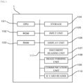
- Fig. 1 is a block diagram illustrating a hardware configuration of an image forming device 1 which is an example of an information processing device according to the embodiment.
- the image forming device 1 has various functions such as a copy function, a facsimile function, and a scanner function.
- the information processing device is not limited to the image forming device 1.
- the image forming device 1 includes a central processing unit (CPU) 101 which is an example of a processor, a read-only memory (ROM) 102, a random access memory (RAM) 103, a storage 104, an input unit 105, a display unit 106, a document reading unit 107, an image forming unit 108, a communication unit 109, and an IC card reader 110. These components are communicatively connected to each other via a bus 111.
- CPU central processing unit
- ROM read-only memory
- RAM random access memory
- the CPU 101 is a central processing unit, and executes various programs and controls each unit. That is, the CPU 101 reads a program from the ROM 102 or the storage 104, and executes the program using the RAM 103 as a work area. The CPU 101 executes control of each of the above-described configurations and various arithmetic processes in accordance with programs recorded in the ROM 102 or the storage 104. In the embodiment, a program is stored in the ROM 102 or the storage 104.
- the ROM 102 stores various programs and various types of data.
- the RAM 103 temporarily stores programs or data as a work area.
- the storage 104 includes a hard disk drive (HDD) or a solid state drive (SSD), and stores various programs including an operating system and various types of data.
- setting information of the executed function is stored as a history in the storage 104.
- the history is displayed as a history operation element 17 on the display unit 106 (see Fig. 5 ).
- a predetermined number of histories for example, 20 histories, can be stored. When the number of histories exceeds, for example, 20, the histories are deleted from the histories of the oldest date and time.
- the setting information to be set varies depending on a function executed by the image forming device 1.
- examples of the setting information include information such as the number of copies, a color mode, magnification, N-up, and a density.
- examples of the setting information include information such as a destination and a density.
- pinned setting information to be distinguished from other histories by an instruction from the user is stored.
- the pinned setting information is displayed as a pinned operation element 18 on the display unit 106 in a case in which the quick icon 16 is selected by the user (see Fig. 5 ).
- the pinned setting information is stored until the user executes a deletion operation.
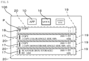
- an image P of "pin" is displayed as illustrated in Fig. 5 , and can be distinguished from the history.
- a pinned menu is displayed to enable pinning, or a pinned menu is displayed in a menu in a case in which a first region 19 (a region where three " " are displayed in the vertical direction illustrated in Fig. 5 ) of history operation element 17 is operated to enable pinning.
- a first region 19 a region where three " " are displayed in the vertical direction illustrated in Fig. 5
- Any type of pinning method by the user can be used.
- the setting information does not depend on the history stored when the function is executed by the user. Even before the function of the image forming device 1 is executed, it may be possible to store information set in advance on the setting screen through a setting operation of the user. Even in this case, similarly to the above-described pinned operation element 18, it is desirable that the image P of the "pin" is displayed and can be distinguished from the history. In the embodiment, description will be made on the assumption that the image P is included in the above-described pinned operation element 18. This case is not limited to a case in which the image P of "pin” similar to that of the pinned operation element 18 is displayed, and another image may be used.
- the input unit 105 includes a pointing device such as a mouse and a keyboard and is used to execute various inputs.
- the input unit 105 is used to set setting information on a setting screen, execute a function, and the like, as described below.
- the touch panel type display unit 106 functions as the input unit 105.
- the display unit 106 is an example of a display device and is, for example, a liquid crystal display.
- the display unit 106 displays various types of information under the control of the CPU 101. A specific display example will be described below.
- the display unit 106 also functions as the input unit 105 by adopting a touch panel system.
- the document reading unit 107 captures documents one by one placed on a sheet feeding table of an automatic feeding device (not illustrated) provided in an upper portion of the image forming device 1, and optically reads the captured documents to obtain image information.
- the document reading unit 107 optically reads a document placed on a table such as a platen glass to obtain image information.
- the image information of the document read by the document reading unit 107 is stored in the storage 104 of the image forming device 1, is printed by the image forming unit 108 to be described below, or is transmitted to another image forming device that has a facsimile (FAX) function by the communication unit 109 to be described below.
- FAX facsimile
- the image forming unit 108 forms, that is, prints, an image which is based on image information obtained by reading by the document reading unit 107 or image information obtained from a personal computer (PC) or the like connected via a network (not illustrated) on a recording medium such as a paper sheet.
- a personal computer PC
- a network not illustrated
- the communication unit 109 connects the image forming device 1 to a public line, and transmits and receives image information obtained through reading by the document reading unit 107 to and from another image forming device that has a FAX function.
- the communication unit 109 may communicate with another device such as a server device (not illustrated) according to a standard such as a public line, the Internet, an intranet, Ethernet (registered trademark), FDDI, or Wi-Fi (registered trademark).
- a server device not illustrated
- a standard such as a public line, the Internet, an intranet, Ethernet (registered trademark), FDDI, or Wi-Fi (registered trademark).
- the IC card reader 110 is a unit that reads information stored in an integrated circuit (IC) card, for example, a user ID. Then, after the IC card reader 110 reads the information stored in the IC card and identifies the user, the function of the image forming device 1 can be executed. After the function of the image forming device 1 is executed, the executed process is stored as a history for each user, as described above, in the storage 104.
- IC integrated circuit
- an IC card in which a user ID or the like is stored as user information needs to be distributed to the user of the image forming device 1.
- the invention is not limited to the case in which a user is specified by causing the IC card reader 110 to read the IC card, and the user may specify the user to use by inputting his or her ID using the input unit 105 without using the IC card reader 110.
- the user information may be registered in advance in the image forming device 1, a list of registered user information may be called and displayed on the display unit 106, and the user to use may be specified by selecting his or her user information from the user information displayed on the display unit 106.
- the history and the pinning to be described below may be common to all users. That is, in a case in which all the users use the common history or pinning setting and it is not necessary to store the history or the pinning for each user, it is not necessary to specify the user to use. Therefore, the IC card reader 110 or the like may not be provided.
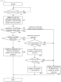
- Fig. 2 is a flowchart illustrating an example of an operation of the image forming device 1 in a case in which the process of the function is executed using the history operation element 17 and the pinned operation element 18.
- step S100 the CPU 101 of the image forming device 1 determines whether or not the user has selected (tapped) the quick icon 16 (see Fig. 3 ) displayed on the display screen of the display unit 106 using the input unit 105 of the image forming device 1. In a case in which it is determined that the quick icon 16 has been selected, the process proceeds to the next step S101. In a case in which it is not determined that the quick icon 16 has been selected, the process proceeds to step S100 again.
- the function of the image forming device 1 is executed without selecting the quick icon 16, for example, as illustrated in Fig. 3
- an icon indicating the function of the image forming device 1 is displayed on the display screen of the display unit 106.
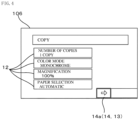
- a setting screen on which setting information regarding the function associated with the selected icon can be set is displayed as illustrated in Fig. 4 .
- the setting operation element 12 in which the number of copies, a color mode, magnification, paper selection, and the like can be set is displayed.
- the user selects the setting operation element 12 of the "number of copies” to set “2 copies” or “3 copies”. Then, "copy” is executed by operating the execution switch 13 displayed in the lower right of the display screen of the display unit 106. Through the execution, the setting information is stored as a history in the storage 104.
- the execution switch 13 is the slide switch 14 in which the process is executed by swiping an arrow portion 14a rightward by a predetermined distance.
- the reason why the swiping operation is executed on the slide switch 14 in this way is that, when the process is executed by a single-tap operation of selecting (tapping) the execution switch 13 once, there may be a problem that, in a case in which the switch is erroneously operated, an unintended billing function is used, or a FAX is sent to an unintended destination, which causes a security problem.
- the execution switch 13 displayed on the display screen of the display unit 106 from the selection of the application icon 10 is the same as the execution switch 13 displayed on the display screen of the display unit 106 by selecting a second region to be described below.
- step S101 the CPU 101 of the image forming device 1 displays a list of the history operation elements 17 and the pinned operation element 18 as operation elements on the display screen of the display unit 106, as illustrated in Fig. 5 .
- each operation element is displayed in a strip form in the horizontal direction on the display screen of the display unit 106.
- the process proceeds to the next step S 102.
- the operation element to be displayed displays the pinned operation element 18 stored in the storage 104 on the upper side, and the history operation element 17 is displayed below the pinned operation element 18 in chronological order.
- the order of the operation elements to be displayed is not limited to the order as illustrated in Fig. 5 .
- the history operation element 17 may be displayed above the pinned operation element 18.
- operation elements to be displayed as illustrated in Fig. 5 , a mixture of the functions of the image forming device 1 is displayed.
- a list is illustrated without distinguishing "Copy”, "Scanner (box storage), and "FAX" from each other.
- the operation elements may be displayed separately for each function of the image forming device 1.
- history operation element 17 and the pinned operation element 18 related to "Copy” may be collectively displayed, then the history operation elements 17 and the pinned operation element 18 related to "Scanner (box storage)" may be displayed as a list, and then the history operation element 17 and the pinned operation element 18 related to "FAX" are displayed.
- step S102 the CPU 101 of the image forming device 1 determines whether the first region 19 (a region in which three ".” are displayed in the vertical direction illustrated in Fig. 5 ) included in the range in which the history operation element 17 and the pinned operation element 18 are displayed is operated or a second region 20 (a region of the operation element other than the region in which three " ⁇ " are displayed in the vertical direction illustrated in Fig. 5 ) is operated.
- the process proceeds to the next step S103.
- step S 104 the operation on the first region 19 and the second region 20 includes, for example, a single-tap operation.
- step S103 the CPU 101 of the image forming device 1 does not display the setting screen in which the stored setting is displayed on the display screen of the display unit 106 as illustrated in Fig. 4 , and displays, as the execution switch 13, a single-tap switch 15 for executing a process by selecting (tapping) the execution switch 13 once. That is, as illustrated in Fig. 6 , when "Execute now" is displayed as the execution switch 13 and the user executes a single tap of "Execute now," the function of the image forming device 1 to which the operation element in which the first region 19 is operated corresponds, for example, "Copy" is executed.
- the single tap is an operation of executing a process of a function of the image forming device 1 by an operation of a shorter time than swiping.
- the list of history operation element 17 and pinned operation element 18 is grayed out, which indicates that "Execute now" which is execution switch 13 can be operated.
- the reason why the process is executed by the single-tap operation instead of the swiping operation in a case in which the process is executed from the history operation element 17 or the pinned operation element 18 is that even in a case in which the execution switch 13 is erroneously operated when the process has been executed in the past, a security problem is less likely to occur. Then, the process ends.
- the operation of the shorter time is an operation in which the user can complete in a shorter time than a comparison target operation.
- the single tap can complete the operation of the shorter time because the user does not slide with his or her finger as compared with the swiping. Since the tap operation is executed once less than the double tap, the operation can be completed in a short time.
- the setting screen in which the setting is displayed is not displayed on the display screen of the display unit 106, and the setting is made unchangeable.
- the setting screen as illustrated in Fig. 4 or a setting screen different from the setting screen as illustrated in Fig. 4 displayed by displaying a "setting change" switch side by side with the single-tap switch 15 and operating the "setting change” switch may be displayed.
- the process may be executed by a swiping operation which is an operation in a case in which the user operates the second region 20 instead of an operation of a shorter time.
- the process of the function of the image forming device 1 may be executed without displaying the execution switch 13 such as "Execute now".
- step S104 as illustrated in Fig. 4 , the CPU 101 of the image forming device 1 displays a setting screen in which the stored setting is displayed on the display screen of the display unit 106, and displays, as the execution switch 13, the slide switch 14 on which the process is executed by swiping the arrow portion 14a rightward by a predetermined distance.
- the execution switch 13 is not limited to the slide switch 14 in which the process is executed by swiping the arrow portion 14a rightward.
- the operation may be a drag operation of moving the arrow portion 14a to another place, a long pressing operation of keeping the operation element pressed for a long time, a double tap operation of selecting (tapping) the execution switch 13 twice, or the like. Then, the process ends.
- the program may be provided in a form of being recorded in a recording medium such as a compact disk read only memory (CD-ROM), a digital versatile disk read only memory (DVD-ROM), or a universal serial bus (USB) memory.
- the program may be downloaded from an external device via a network.
- the slide switch 14 is swiped as the execution switch 13.
- the execution switch 13 may be set to execute a process by a swiping operation instead of a single-tap operation which is an operation of a shorter time.
- the execution switch 13 may be set to execute a process by a single-tap operation which is an operation of a shorter time according to a machine setting of the image forming device 1.
- the swiping operation is executed on the slide switch 14.
- the single tap operation may be executed.
- the swiping operation may be executed.
- the setting is not changed even if the second region 20 is operated, a single-tap operation which is an operation of a shorter time similar to the case in which the first region 19 is operated is enabled to achieve convenience for the user.
- Fig. 7 illustrates a flowchart in which the first modified example and a second modified example in which execution of a process by a single-tap operation is set in accordance with a machine setting of the image forming device 1 are adopted even in a case in which the second region 20 is operated in the above-described first modified example.
- step S200 the CPU 101 of the image forming device 1 determines whether or not the user has selected (tapped) the quick icon 16 using the input unit 105 of the image forming device 1. In a case in which it is determined that the quick icon 16 has been selected, the process proceeds to the next step S201. In a case in which it is not determined that the quick icon 16 has been selected, the process proceeds to step S200 again.
- step S201 as illustrated in Fig. 5 , the history operation element 17 and the pinned operation element 18 are displayed as operation elements on the display screen of the display unit 106 by the CPU 101 of the image forming device 1. Then, the process proceeds to the next step S202.
- step S202 the CPU 101 of the image forming device 1 determines whether the first region 19 included in the range in which the history operation element 17 and the pinned operation element 18 are displayed has been operated or the second region 20 has been operated. When it is determined that the first region 19 has been operated, the process proceeds to the next step S203. Conversely, when it is determined that the first region 19 has not been operated and the second region 20 has been operated, the process proceeds to step S210.
- the operation on the first region 19 and the second region 20 includes, for example, a single-tap operation.
- step S203 the CPU 101 of the image forming device 1 does not display the setting screen in which the stored setting is displayed on the display screen of the display unit 106 as illustrated in Fig. 4 , and displays, as the execution switch 13, the single-tap switch 15 for executing the process by selecting (tapping) the execution switch 13 once. That is, as illustrated in Fig. 6 , when "Execute now" is displayed as the execution switch 13 and the user executes a single tap of "Execute now," the function of the image forming device 1 to which the operation element in which the first region 19 is operated corresponds, for example, "Copy" is executed.
- the single tap is an operation of executing a process of a function of the image forming device 1 by an operation of a shorter time than swiping.
- the list of history operation element 17 and pinned operation element 18 is grayed out, which indicates that "Execute now" which is execution switch 13 can be operated. Then, the process ends.
- step S210 as in the above-described first modified example, it is determined whether or not the setting is a single-tap operation. In a case in which it is determined that the setting is the single-tap operation, the process proceeds to the next step S211. In a case in which it is determined that the setting is not the single-tap operation, that is, in a case in which the setting is the swiping operation, the process proceeds to step S214.
- step S211 the setting screen is displayed on the display screen of the display unit 106. Then, the process proceeds to the next step S212.
- step S212 it is determined whether or not the setting has been changed by the user. In a case in which it is determined that the setting is not changed by the user, the process proceeds to the next step S213. In a case in which it is determined that the setting is changed by the user, the process proceeds to step S214.
- step S213 as illustrated in Fig. 8 , the single-tap switch 15 is displayed on the display screen of the display unit 106.
- Fig. 8 for example, it is displayed that the "magnification” has been changed from "100%” to "two sheets ⁇ one sheet (N up)". Then, the process ends.
- step S214 as illustrated in Fig. 4 , the setting screen is displayed on the display screen of the display unit 106, and the slide switch 14 is displayed. Then, the process ends.
- step S211 and step S212 are omitted from the flowchart of Fig. 7 , and the process proceeds to step S213 after step S210.
- step S210 is omitted from the flowchart of Fig. 7 , and step S211 is executed after step S202.
- a single-tap operation which is an operation of a shorter time can be executed by selecting the first region 19 from both the history operation element 17 and the pinned operation element 18.
- the history operation element 17 is limited so that the single-tap operation which is an operation of a shorter time cannot be executed even if the first region 19 is selected. Only in the case of the pinned operation element 18, the first region 19 is selected so that the operation of the shorter time can be executed.
- Fig. 9 is a flowchart illustrating an example of the operation of the image forming device 1 in a case in which the process of the function is executed using the history operation element 17 and the pinned operation element 18.
- step S300 the CPU 101 of the image forming device 1 determines whether or not the user has selected (tapped) the quick icon 16 using the input unit 105 of the image forming device 1. In a case in which it is determined that the quick icon 16 has been selected, the process proceeds to the next step S301. In a case in which it is not determined that the quick icon 16 has been selected, the process proceeds to step S300 again.
- step S301 as illustrated in Fig. 5 , the history operation element 17 and the pinned operation element 18 are displayed as operation elements on the display screen of the display unit 106 by the CPU 101 of the image forming device 1. Then, the process proceeds to the next step S302.
- step S302 it is determined whether or not the pinned operation element 18 has been operated. In a case in which it is determined that pinned operation element 18 has been operated, the process proceeds to next step S303. Conversely, in a case in which it is not determined that pinned operation element 18 has been operated, that is, in a case in which it is determined that history operation element 17 has been operated, the process proceeds to step S305.
- step S303 the CPU 101 of the image forming device 1 determines whether the first region 19 included in the range in which the pinned operation element 18 is displayed has been operated or the second region 20 has been operated. In a case in which it is determined that the first region 19 has been operated, the process proceeds to the next step S303. Conversely, in a case in which it is determined that the first region 19 has not been operated and the second region 20 has been operated, the process proceeds to step S305.
- the operation on the first region 19 and the second region 20 includes, for example, a single-tap operation.
- step S304 the CPU 101 of the image forming device 1 does not display the setting screen in which the stored setting is displayed on the display screen of the display unit 106 as illustrated in Fig. 4 , and displays, as the execution switch 13, the single-tap switch 15 for executing the process by selecting (tapping) the execution switch 13 once. That is, as illustrated in Fig. 6 , when "Execute now" is displayed as the execution switch 13 and the user executes a single tap of "Execute now," the function of the image forming device 1 to which the operation element in which the first region 19 is operated corresponds, for example, "Copy" is executed.
- the single tap is an operation of executing a process of a function of the image forming device 1 by an operation of a shorter time than swiping.
- the list of history operation element 17 and pinned operation element 18 is grayed out, which indicates that "Execute now" which is execution switch 13 can be operated. Then, the process ends.
- step S305 as illustrated in Fig. 4 , the CPU 101 of the image forming device 1 displays a setting screen in which the stored setting is displayed on the display screen of the display unit 106, and displays, as the execution switch 13, the slide switch 14 on which the process is executed by swiping the arrow portion 14a rightward by a predetermined distance. Therefore, when the history operation element 17 is operated, a single-tap operation which is an operation of a shorter time is inhibited from being executed.
- the execution switch 13 is not limited to the slide switch 14 in which the process is executed by swiping the arrow portion 14a rightward.
- the operation may be a drag operation of moving the arrow portion 14a to another place, a long pressing operation of keeping the operation element pressed for a long time, a double tap operation of selecting (tapping) the execution switch 13 twice, or the like. Then, the process ends.
- first region 19 of the pinned operation element 18 is selected or the other region (the second region 20 of the pinned operation element 18, the first region 19 of the history operation element 17, or the second region 20) is selected in one step without separating the above-described steps S302 and S303.
- Fig. 10 illustrates a flowchart in which, in the first modified example of the first embodiment described above, the first modified example and the second modified example in which the execution of the process by the single-tap operation is set by the machine setting of the image forming device 1 even in a case in which the second region 20 is operated are applied to the second embodiment.
- step S400 the CPU 101 of the image forming device 1 determines whether or not the user has selected (tapped) the quick icon 16 using the input unit 105 of the image forming device 1. In a case in which it is determined that the quick icon 16 has been selected, the process proceeds to the next step S401. In a case in which it is not determined that the quick icon 16 has been selected, the process proceeds to step S400 again.
- step S401 as illustrated in Fig. 5 , the history operation element 17 and the pinned operation element 18 are displayed as operation elements on the display screen of the display unit 106 by the CPU 101 of the image forming device 1. Then, the process proceeds to the next step S402.
- step S402 it is determined whether or not the pinned operation element 18 has been operated. In a case in which it is determined that pinned operation element 18 has been operated, the process proceeds to next step S403. Conversely, in a case in which it is not determined that pinned operation element 18 has been operated, that is, in a case in which it is determined that history operation element 17 has been operated, the process proceeds to step S414.
- step S403 the CPU 101 of the image forming device 1 determines whether the first region 19 included in the range in which the pinned operation element 18 is displayed has been operated or the second region 20 has been operated. In a case in which it is determined that the first region 19 has been operated, the process proceeds to the next step S404. Conversely, in a case in which it is determined that the first region 19 has not been operated and the second region 20 has been operated, the process proceeds to step S410.
- the operation on the first region 19 and the second region 20 includes, for example, a single-tap operation.
- step S404 the CPU 101 of the image forming device 1 does not display the setting screen in which the stored setting is displayed on the display screen of the display unit 106 as illustrated in Fig. 4 , and displays, as the execution switch 13, the single-tap switch 15 for executing the process by selecting (tapping) the execution switch 13 once. That is, as illustrated in Fig. 6 , when "Execute now" is displayed as the execution switch 13 and the user executes a single tap of "Execute now," the function of the image forming device 1 to which the operation element in which the first region 19 is operated corresponds, for example, "Copy" is executed.
- the single tap is an operation of executing a process of a function of the image forming device 1 by an operation of a shorter time than swiping.
- the list of history operation element 17 and pinned operation element 18 is grayed out, which indicates that "Execute now" which is execution switch 13 can be operated. Then, the process ends.
- step S410 as in the above-described first modified example, it is determined whether or not the setting is a single-tap operation. In a case in which it is determined that the setting is the single-tap operation, the process proceeds to the next step S411. In a case in which it is not determined that the setting is the single-tap operation, that is, in a case in which the setting is the swiping operation, the process proceeds to step S414.
- step S411 the setting screen is displayed on the display screen of the display unit 106. Then, the process proceeds to the next step S412.
- step S412 it is determined whether or not the setting has been changed by the user. In a case in which it is determined that the setting is not changed by the user, the process proceeds to the next step S413. In a case in which it is determined that the setting is changed by the user, the process proceeds to step S414.
- step S413 as illustrated in Fig. 8 , the single-tap switch 15 is displayed on the display screen of the display unit 106.
- Fig. 8 for example, it is displayed that the "magnification” has been changed from "100%” to "two sheets ⁇ one sheet (N up)". Then, the process ends.
- step S414 as illustrated in Fig. 4 , the setting screen is displayed on the display screen of the display unit 106, and the slide switch 14 is displayed. Then, the process ends.
- step S411 and S412 are omitted from the flowchart of Fig. 10 , and the process proceeds to step S413 after step S410.
- step S410 is omitted from the flowchart of Fig. 7 , and step S411 is executed after step S403.
- a processor is a processor in a broad sense, and includes a general-purpose processor (for example, a central processing unit (CPU) or the like) or a dedicated processor (for example, a graphics processing unit (GPU), an application specific integrated circuit (ASIC), a field programmable gate array (FPGA), a programmable logic device, and the like).
- a general-purpose processor for example, a central processing unit (CPU) or the like
- a dedicated processor for example, a graphics processing unit (GPU), an application specific integrated circuit (ASIC), a field programmable gate array (FPGA), a programmable logic device, and the like.
- the operation of the processor in the above-described embodiment may be executed not only by one processor but also by cooperation of a plurality of processors existing at physically separated positions.
- the order of operations of the processor is not limited to the order described in each of the above-described embodiments, and may be appropriately changed.
Landscapes
- Engineering & Computer Science (AREA)
- General Engineering & Computer Science (AREA)
- Theoretical Computer Science (AREA)
- Human Computer Interaction (AREA)
- Physics & Mathematics (AREA)
- General Physics & Mathematics (AREA)
- Multimedia (AREA)
- Signal Processing (AREA)
- User Interface Of Digital Computer (AREA)
- Facsimiles In General (AREA)
- Accessory Devices And Overall Control Thereof (AREA)
Abstract
Description
- The technology of the present disclosure relates to an information processing device and an information processing program.
- Japanese Patent Application Laid-Open (
JP-A) No. 2017-97496 - There is an information processing device that receives a processing instruction in a case in which an operation element displayed on a display device is operated by an operation requiring a certain period of time, such as a slide operation. Since an operation such as a slide operation is more complicated than a simple operation such as a simple touch operation, it is difficult to unintentionally receive an instruction. In this regard, a time-consuming operation requires more input labor for the user than a simple operation.
- An object of the technology of the present disclosure is to provide an information processing device and an information processing program capable of receiving an instruction to execute a process for a shorter time than in a case in which execution of all processes are received by a time-consuming operation.
- An information processing device according to a first aspect includes a processor. The processor may display, on a display device, an operation element that is configured to receive an instruction of a process involving a setting set by a user. In a case in which a first region, included in a range in which the operation element is displayed, is operated, the process may be executed by an operation of a shorter time compared with a case in which a second region, that is a region different from the first region and included in the range in which the operation element is displayed, is operated.
- In the information processing device according to a second aspect, the operation element may include a history operation element displayed on the display device by executing a process in a setting related to the process.
- In the information processing device according to a third aspect, the operation element may include a pinned operation element that is pinned by an instruction from the user, to be distinguished from other history operation elements from a list of history operation elements displayed on the display device, by executing the process in a setting related to the process.
- In the information processing device according to a fourth aspect, in a case in which a range, in which the history operation element is displayed, is operated, a restriction may be imposed so that the operation of the shorter time is not executable.
- In the information processing device according to a fifth aspect, at a time of pinning, execution of an operation other than the operation of the shorter time even in a case in which the first region is operated, or execution of the operation of the shorter time even in a case in which the second region is operated, are be able to be set by an operation of the user.
- In the information processing device according to a sixth aspect, the operation element may include an operation element displayed on the display device by a setting operation of the user before the process is executed.
- In the information processing device according to a seventh aspect, in a case in which the first region is operated by the user and the process is executed by the operation of the shorter time, a setting screen on which the setting of the process is changeable need not be displayed on the display device.
- In the information processing device according to an eighth aspect, even in a case in which the first region is operated, the process is executed by the operation of the case in which the second region has been operated, if the setting has been changed by a user operation on a setting screen on which the setting of the process is changeable, or on a setting screen that is different from the setting screen, before the process is executed by the operation of the shorter time.
- An information processing program according to a ninth aspect causes a computer to function as the information processing device according to any one of the first to eighth aspects. Advantageous Effects of Invention
- According to the first aspect, there is an advantageous effect that a long-time operation is not required in accordance with an area to be operated, as compared with a case in which an execution instruction by a long-time operation is required for all execution operations.
- According to the second aspect, there is an advantageous effect that a process can be executed by an operation of a shorter time in an operation which is based on a history of past execution.
- According to the third aspect, there is an advantageous effect that a process can be executed by an operation of a shorter time in an operation which is based on a history pinned from a history of past execution.
- According to the fourth aspect, there is an advantageous effect that a process can be executed by an operation of a shorter time in an operation based on a history pinned from a history of past execution, but a process by an operation of a shorter time can be prevented from being executed from an unpinned history.
- According to the fifth aspect, there is an advantageous effect that in the machine setting of the information processing device, it is possible to set execution of an operation other than an operation of a shorter time even in a case in which an operation is executed on the first region or execution of an operation of a shorter time even in a case in which an operation is executed on the second region, so that it is possible to provide an information processing device that suits a user preference as compared with a case in which the setting is disabled.
- According to the sixth aspect, there is an advantageous effect that, regardless of the history of past executions, a process by an operation of a shorter time can be executed by a user executing a setting operation in advance.
- According to the seventh aspect, there is an advantageous effect that, in a case in which the process is executed by an operation of a shorter time, the setting cannot be changed, so that the process can be prevented from being executed due to an erroneous operation of a shorter time as compared with a case in which the setting can be changed.
- According to the eighth aspect, there is an advantageous effect that, in a case in which the setting is changed, the process is executed not by the operation of the shorter time in a case in which the first region is operated but by the operation in a case in which the second region is operated, so that the process can be prevented from being executed by an erroneous operation of a shorter time.
- According to the ninth aspect, it is possible to provide an information processing program capable of making a long-time operation unrequired in accordance with an area to be operated, as compared with a case in which an execution instruction by a long-time operation is required for all execution operations.
-
-
Fig. 1 is a schematic block diagram illustrating an image forming device according to a first embodiment of the present invention. -
Fig. 2 is a flowchart illustrating an example of an operation of the information processing device according to the first embodiment of the invention. -
Fig. 3 is an explanatory diagram illustrating an example of a display screen of a display unit according to the first embodiment of the invention. -
Fig. 4 is an explanatory diagram illustrating an example of the display screen of the display unit according to the first embodiment of the invention. -
Fig. 5 is an explanatory diagram illustrating an example of the display screen of the display unit according to the first embodiment of the invention. -
Fig. 6 is an explanatory diagram illustrating an example of a display screen of the display unit according to the first embodiment of the invention. -
Fig. 7 is a flowchart illustrating an example of an operation of an information processing device according to a modified example of the first embodiment of the invention. -
Fig. 8 is an explanatory diagram illustrating an example of a display screen of a display unit according to a modified example of the first embodiment of the invention. -
Fig. 9 is a flowchart illustrating an example of an operation of the information processing device according to a second embodiment of the invention. -
Fig. 10 is a flowchart illustrating an example of an operation of an information processing device according to a modified example of the second embodiment of the invention. - Hereinafter, an example of an embodiment of the present disclosure will be described with reference to the drawings. In the drawings, the same or equivalent components and portions are denoted by the same reference numerals. Dimensional ratios in the drawings are exaggerated for facilitating description, and may be different from actual ratios.
-
Fig. 1 is a block diagram illustrating a hardware configuration of animage forming device 1 which is an example of an information processing device according to the embodiment. - Here, the
image forming device 1 has various functions such as a copy function, a facsimile function, and a scanner function. - The information processing device is not limited to the
image forming device 1. - As illustrated in
Fig. 1 , theimage forming device 1 includes a central processing unit (CPU) 101 which is an example of a processor, a read-only memory (ROM) 102, a random access memory (RAM) 103, astorage 104, aninput unit 105, adisplay unit 106, adocument reading unit 107, animage forming unit 108, acommunication unit 109, and anIC card reader 110. These components are communicatively connected to each other via abus 111. - The
CPU 101 is a central processing unit, and executes various programs and controls each unit. That is, theCPU 101 reads a program from theROM 102 or thestorage 104, and executes the program using theRAM 103 as a work area. TheCPU 101 executes control of each of the above-described configurations and various arithmetic processes in accordance with programs recorded in theROM 102 or thestorage 104. In the embodiment, a program is stored in theROM 102 or thestorage 104. - The
ROM 102 stores various programs and various types of data. TheRAM 103 temporarily stores programs or data as a work area. Thestorage 104 includes a hard disk drive (HDD) or a solid state drive (SSD), and stores various programs including an operating system and various types of data. - When the user executes a process of a function of the
image forming device 1, setting information of the executed function is stored as a history in thestorage 104. As will be described below, when the user selects aquick icon 16, the history is displayed as ahistory operation element 17 on the display unit 106 (seeFig. 5 ). A predetermined number of histories, for example, 20 histories, can be stored. When the number of histories exceeds, for example, 20, the histories are deleted from the histories of the oldest date and time. Here, the setting information to be set varies depending on a function executed by theimage forming device 1. In the case of "copy", examples of the setting information include information such as the number of copies, a color mode, magnification, N-up, and a density. In the case of "FAX", examples of the setting information include information such as a destination and a density. - From a list of the histories stored by executing processes of functions of the
image forming device 1, pinned setting information to be distinguished from other histories by an instruction from the user is stored. As will be described below, the pinned setting information is displayed as a pinnedoperation element 18 on thedisplay unit 106 in a case in which thequick icon 16 is selected by the user (seeFig. 5 ). The pinned setting information is stored until the user executes a deletion operation. Here, in a case in which the pinned setting information is displayed as the pinnedoperation element 18 on thedisplay unit 106, in the embodiment, an image P of "pin" is displayed as illustrated inFig. 5 , and can be distinguished from the history. By operating a long pressing operation onhistory operation element 17, a pinned menu is displayed to enable pinning, or a pinned menu is displayed in a menu in a case in which a first region 19 (a region where three " " are displayed in the vertical direction illustrated inFig. 5 ) ofhistory operation element 17 is operated to enable pinning. Any type of pinning method by the user can be used. - The setting information does not depend on the history stored when the function is executed by the user. Even before the function of the
image forming device 1 is executed, it may be possible to store information set in advance on the setting screen through a setting operation of the user. Even in this case, similarly to the above-described pinnedoperation element 18, it is desirable that the image P of the "pin" is displayed and can be distinguished from the history. In the embodiment, description will be made on the assumption that the image P is included in the above-described pinnedoperation element 18. This case is not limited to a case in which the image P of "pin" similar to that of the pinnedoperation element 18 is displayed, and another image may be used. - The
input unit 105 includes a pointing device such as a mouse and a keyboard and is used to execute various inputs. Theinput unit 105 is used to set setting information on a setting screen, execute a function, and the like, as described below. In the embodiment, the touch paneltype display unit 106 functions as theinput unit 105. - The
display unit 106 is an example of a display device and is, for example, a liquid crystal display. Thedisplay unit 106 displays various types of information under the control of theCPU 101. A specific display example will be described below. Thedisplay unit 106 also functions as theinput unit 105 by adopting a touch panel system. - The
document reading unit 107 captures documents one by one placed on a sheet feeding table of an automatic feeding device (not illustrated) provided in an upper portion of theimage forming device 1, and optically reads the captured documents to obtain image information. Alternatively, thedocument reading unit 107 optically reads a document placed on a table such as a platen glass to obtain image information. - Here, the image information of the document read by the
document reading unit 107 is stored in thestorage 104 of theimage forming device 1, is printed by theimage forming unit 108 to be described below, or is transmitted to another image forming device that has a facsimile (FAX) function by thecommunication unit 109 to be described below. - The
image forming unit 108 forms, that is, prints, an image which is based on image information obtained by reading by thedocument reading unit 107 or image information obtained from a personal computer (PC) or the like connected via a network (not illustrated) on a recording medium such as a paper sheet. - The
communication unit 109 connects theimage forming device 1 to a public line, and transmits and receives image information obtained through reading by thedocument reading unit 107 to and from another image forming device that has a FAX function. - The
communication unit 109 may communicate with another device such as a server device (not illustrated) according to a standard such as a public line, the Internet, an intranet, Ethernet (registered trademark), FDDI, or Wi-Fi (registered trademark). - The
IC card reader 110 is a unit that reads information stored in an integrated circuit (IC) card, for example, a user ID. Then, after theIC card reader 110 reads the information stored in the IC card and identifies the user, the function of theimage forming device 1 can be executed. After the function of theimage forming device 1 is executed, the executed process is stored as a history for each user, as described above, in thestorage 104. - As the premise, an IC card in which a user ID or the like is stored as user information needs to be distributed to the user of the
image forming device 1. - The invention is not limited to the case in which a user is specified by causing the
IC card reader 110 to read the IC card, and the user may specify the user to use by inputting his or her ID using theinput unit 105 without using theIC card reader 110. Alternatively, the user information may be registered in advance in theimage forming device 1, a list of registered user information may be called and displayed on thedisplay unit 106, and the user to use may be specified by selecting his or her user information from the user information displayed on thedisplay unit 106. - Without specifying the user who uses the
image forming device 1, the history and the pinning to be described below may be common to all users. That is, in a case in which all the users use the common history or pinning setting and it is not necessary to store the history or the pinning for each user, it is not necessary to specify the user to use. Therefore, theIC card reader 110 or the like may not be provided. - Next, operational effects of the
image forming device 1 will be described. -
Fig. 2 is a flowchart illustrating an example of an operation of theimage forming device 1 in a case in which the process of the function is executed using thehistory operation element 17 and the pinnedoperation element 18. - As illustrated in
Fig. 2 , in step S100, theCPU 101 of theimage forming device 1 determines whether or not the user has selected (tapped) the quick icon 16 (seeFig. 3 ) displayed on the display screen of thedisplay unit 106 using theinput unit 105 of theimage forming device 1. In a case in which it is determined that thequick icon 16 has been selected, the process proceeds to the next step S101. In a case in which it is not determined that thequick icon 16 has been selected, the process proceeds to step S100 again. - Here, in a case in which the function of the
image forming device 1 is executed without selecting thequick icon 16, for example, as illustrated inFig. 3 , when theapplication icon 10 displayed on the display screen of thedisplay unit 106 is selected, an icon indicating the function of theimage forming device 1 is displayed on the display screen of thedisplay unit 106. Then, when the user selects any of the icons, for example, thecopy icon 11, a setting screen on which setting information regarding the function associated with the selected icon can be set is displayed as illustrated inFig. 4 . In this example, the settingoperation element 12 in which the number of copies, a color mode, magnification, paper selection, and the like can be set is displayed. For example, in a case in which the number of copies is changed from an initial setting "1 copy" in the setting information, the user selects thesetting operation element 12 of the "number of copies" to set "2 copies" or "3 copies". Then, "copy" is executed by operating theexecution switch 13 displayed in the lower right of the display screen of thedisplay unit 106. Through the execution, the setting information is stored as a history in thestorage 104. Here, theexecution switch 13 is the slide switch 14 in which the process is executed by swiping an arrow portion 14a rightward by a predetermined distance. The reason why the swiping operation is executed on the slide switch 14 in this way is that, when the process is executed by a single-tap operation of selecting (tapping) theexecution switch 13 once, there may be a problem that, in a case in which the switch is erroneously operated, an unintended billing function is used, or a FAX is sent to an unintended destination, which causes a security problem. In addition, theexecution switch 13 displayed on the display screen of thedisplay unit 106 from the selection of theapplication icon 10 is the same as theexecution switch 13 displayed on the display screen of thedisplay unit 106 by selecting a second region to be described below. - In step S101, the
CPU 101 of theimage forming device 1 displays a list of thehistory operation elements 17 and the pinnedoperation element 18 as operation elements on the display screen of thedisplay unit 106, as illustrated inFig. 5 . Here, as illustrated inFig. 5 , each operation element is displayed in a strip form in the horizontal direction on the display screen of thedisplay unit 106. Then, the process proceeds to thenext step S 102. As illustrated inFig. 5 , the operation element to be displayed displays the pinnedoperation element 18 stored in thestorage 104 on the upper side, and thehistory operation element 17 is displayed below the pinnedoperation element 18 in chronological order. The order of the operation elements to be displayed is not limited to the order as illustrated inFig. 5 . For example, thehistory operation element 17 may be displayed above the pinnedoperation element 18. For operation elements to be displayed, as illustrated inFig. 5 , a mixture of the functions of theimage forming device 1 is displayed. For example, a list is illustrated without distinguishing "Copy", "Scanner (box storage), and "FAX" from each other. However, may be invention is not limited thereto, and the operation elements may be displayed separately for each function of theimage forming device 1. For example, only thehistory operation element 17 and the pinnedoperation element 18 related to "Copy" may be collectively displayed, then thehistory operation elements 17 and the pinnedoperation element 18 related to "Scanner (box storage)" may be displayed as a list, and then thehistory operation element 17 and the pinnedoperation element 18 related to "FAX" are displayed. - In step S102, the
CPU 101 of theimage forming device 1 determines whether the first region 19 (a region in which three "." are displayed in the vertical direction illustrated inFig. 5 ) included in the range in which thehistory operation element 17 and the pinnedoperation element 18 are displayed is operated or a second region 20 (a region of the operation element other than the region in which three "·" are displayed in the vertical direction illustrated inFig. 5 ) is operated. In a case in which it is determined that thefirst region 19 has been operated, the process proceeds to the next step S103. Conversely, when it is determined that thefirst region 19 has not been operated and thesecond region 20 has been operated, the process proceeds to stepS 104. The operation on thefirst region 19 and thesecond region 20 includes, for example, a single-tap operation. - In step S103, the
CPU 101 of theimage forming device 1 does not display the setting screen in which the stored setting is displayed on the display screen of thedisplay unit 106 as illustrated inFig. 4 , and displays, as theexecution switch 13, a single-tap switch 15 for executing a process by selecting (tapping) theexecution switch 13 once. That is, as illustrated inFig. 6 , when "Execute now" is displayed as theexecution switch 13 and the user executes a single tap of "Execute now," the function of theimage forming device 1 to which the operation element in which thefirst region 19 is operated corresponds, for example, "Copy" is executed. Here, the single tap is an operation of executing a process of a function of theimage forming device 1 by an operation of a shorter time than swiping. InFig. 6 , the list ofhistory operation element 17 and pinnedoperation element 18 is grayed out, which indicates that "Execute now" which isexecution switch 13 can be operated. The reason why the process is executed by the single-tap operation instead of the swiping operation in a case in which the process is executed from thehistory operation element 17 or the pinnedoperation element 18 is that even in a case in which theexecution switch 13 is erroneously operated when the process has been executed in the past, a security problem is less likely to occur. Then, the process ends. The operation of the shorter time is an operation in which the user can complete in a shorter time than a comparison target operation. For example, the single tap can complete the operation of the shorter time because the user does not slide with his or her finger as compared with the swiping. Since the tap operation is executed once less than the double tap, the operation can be completed in a short time. - In a case in which the
first region 19 is operated and the process is executed by the single tap which is an operation of a shorter time, the setting screen in which the setting is displayed is not displayed on the display screen of thedisplay unit 106, and the setting is made unchangeable. However, the invention is not limited thereto. The setting screen as illustrated inFig. 4 or a setting screen different from the setting screen as illustrated inFig. 4 displayed by displaying a "setting change" switch side by side with the single-tap switch 15 and operating the "setting change" switch may be displayed. In a case in which the user changes the setting, the process may be executed by a swiping operation which is an operation in a case in which the user operates thesecond region 20 instead of an operation of a shorter time. In addition, when thefirst region 19 is operated, the process of the function of theimage forming device 1 may be executed without displaying theexecution switch 13 such as "Execute now". - In step S104, as illustrated in
Fig. 4 , theCPU 101 of theimage forming device 1 displays a setting screen in which the stored setting is displayed on the display screen of thedisplay unit 106, and displays, as theexecution switch 13, the slide switch 14 on which the process is executed by swiping the arrow portion 14a rightward by a predetermined distance. Theexecution switch 13 is not limited to the slide switch 14 in which the process is executed by swiping the arrow portion 14a rightward. As long as the operation is an operation in which it takes more time than a single tap and which is complicated, the operation may be a drag operation of moving the arrow portion 14a to another place, a long pressing operation of keeping the operation element pressed for a long time, a double tap operation of selecting (tapping) theexecution switch 13 twice, or the like. Then, the process ends. - In each of the above embodiments, the aspect in which a program of a collection destination specifying process is stored (installed) in advance in the
ROM 102 or the storage unit (storage) 104 has been described, but the invention is not limited thereto. The program may be provided in a form of being recorded in a recording medium such as a compact disk read only memory (CD-ROM), a digital versatile disk read only memory (DVD-ROM), or a universal serial bus (USB) memory. The program may be downloaded from an external device via a network. - The invention is not limited to the above-described first embodiment and various modifications and applications can be made without departing from the gist of the invention.
- A first modified example will be described. In the above-described first embodiment, in a case in which the
first region 19 is not operated and thesecond region 20 is operated, the slide switch 14 is swiped as theexecution switch 13. However, even in a case in which thefirst region 19 is operated, theexecution switch 13 may be set to execute a process by a swiping operation instead of a single-tap operation which is an operation of a shorter time. Even in a case in which thesecond region 20 is operated, theexecution switch 13 may be set to execute a process by a single-tap operation which is an operation of a shorter time according to a machine setting of theimage forming device 1. - Furthermore, a second modified example will be described. In the above-described embodiment, in a case in which the
first region 19 is not operated and thesecond region 20 is operated, the swiping operation is executed on the slide switch 14. However, in a case in which the setting is not changed, the single tap operation may be executed. In a case in which the setting is changed, that is, in a case in which the number of copies, the magnification, or the like is changed, the swiping operation may be executed. In this case, since the setting is not changed even if thesecond region 20 is operated, a single-tap operation which is an operation of a shorter time similar to the case in which thefirst region 19 is operated is enabled to achieve convenience for the user. -
Fig. 7 illustrates a flowchart in which the first modified example and a second modified example in which execution of a process by a single-tap operation is set in accordance with a machine setting of theimage forming device 1 are adopted even in a case in which thesecond region 20 is operated in the above-described first modified example. - As illustrated in
Fig. 7 , in step S200, theCPU 101 of theimage forming device 1 determines whether or not the user has selected (tapped) thequick icon 16 using theinput unit 105 of theimage forming device 1. In a case in which it is determined that thequick icon 16 has been selected, the process proceeds to the next step S201. In a case in which it is not determined that thequick icon 16 has been selected, the process proceeds to step S200 again. - In step S201, as illustrated in
Fig. 5 , thehistory operation element 17 and the pinnedoperation element 18 are displayed as operation elements on the display screen of thedisplay unit 106 by theCPU 101 of theimage forming device 1. Then, the process proceeds to the next step S202. - In step S202, the
CPU 101 of theimage forming device 1 determines whether thefirst region 19 included in the range in which thehistory operation element 17 and the pinnedoperation element 18 are displayed has been operated or thesecond region 20 has been operated. When it is determined that thefirst region 19 has been operated, the process proceeds to the next step S203. Conversely, when it is determined that thefirst region 19 has not been operated and thesecond region 20 has been operated, the process proceeds to step S210. The operation on thefirst region 19 and thesecond region 20 includes, for example, a single-tap operation. - In step S203, the
CPU 101 of theimage forming device 1 does not display the setting screen in which the stored setting is displayed on the display screen of thedisplay unit 106 as illustrated inFig. 4 , and displays, as theexecution switch 13, the single-tap switch 15 for executing the process by selecting (tapping) theexecution switch 13 once. That is, as illustrated inFig. 6 , when "Execute now" is displayed as theexecution switch 13 and the user executes a single tap of "Execute now," the function of theimage forming device 1 to which the operation element in which thefirst region 19 is operated corresponds, for example, "Copy" is executed. Here, the single tap is an operation of executing a process of a function of theimage forming device 1 by an operation of a shorter time than swiping. InFig. 6 , the list ofhistory operation element 17 and pinnedoperation element 18 is grayed out, which indicates that "Execute now" which isexecution switch 13 can be operated. Then, the process ends. - In step S210, as in the above-described first modified example, it is determined whether or not the setting is a single-tap operation. In a case in which it is determined that the setting is the single-tap operation, the process proceeds to the next step S211. In a case in which it is determined that the setting is not the single-tap operation, that is, in a case in which the setting is the swiping operation, the process proceeds to step S214.
- In step S211, the setting screen is displayed on the display screen of the
display unit 106. Then, the process proceeds to the next step S212. - In step S212, it is determined whether or not the setting has been changed by the user. In a case in which it is determined that the setting is not changed by the user, the process proceeds to the next step S213. In a case in which it is determined that the setting is changed by the user, the process proceeds to step S214.
- In step S213, as illustrated in
Fig. 8 , the single-tap switch 15 is displayed on the display screen of thedisplay unit 106. Here, inFig. 8 , for example, it is displayed that the "magnification" has been changed from "100%" to "two sheets → one sheet (N up)". Then, the process ends. - In step S214, as illustrated in
Fig. 4 , the setting screen is displayed on the display screen of thedisplay unit 106, and the slide switch 14 is displayed. Then, the process ends. - Although the description has been given using the flowchart in which the two modified examples are adopted, only one of the modified examples may be adopted. In a case in which only the first modified example is adopted, step S211 and step S212 are omitted from the flowchart of
Fig. 7 , and the process proceeds to step S213 after step S210. In a case in which only the second modified example is adopted, step S210 is omitted from the flowchart ofFig. 7 , and step S211 is executed after step S202. - Next, a second embodiment will be described.
- In the above-described first embodiment, a single-tap operation which is an operation of a shorter time can be executed by selecting the
first region 19 from both thehistory operation element 17 and the pinnedoperation element 18. In the second embodiment, thehistory operation element 17 is limited so that the single-tap operation which is an operation of a shorter time cannot be executed even if thefirst region 19 is selected. Only in the case of the pinnedoperation element 18, thefirst region 19 is selected so that the operation of the shorter time can be executed. - Here, portions different from those of the above-described first embodiment will be mainly described, and description of the repeated portions will be simplified or omitted.
-
Fig. 9 is a flowchart illustrating an example of the operation of theimage forming device 1 in a case in which the process of the function is executed using thehistory operation element 17 and the pinnedoperation element 18. - In step S300, the
CPU 101 of theimage forming device 1 determines whether or not the user has selected (tapped) thequick icon 16 using theinput unit 105 of theimage forming device 1. In a case in which it is determined that thequick icon 16 has been selected, the process proceeds to the next step S301. In a case in which it is not determined that thequick icon 16 has been selected, the process proceeds to step S300 again. - In step S301, as illustrated in
Fig. 5 , thehistory operation element 17 and the pinnedoperation element 18 are displayed as operation elements on the display screen of thedisplay unit 106 by theCPU 101 of theimage forming device 1. Then, the process proceeds to the next step S302. - In step S302, it is determined whether or not the pinned
operation element 18 has been operated. In a case in which it is determined that pinnedoperation element 18 has been operated, the process proceeds to next step S303. Conversely, in a case in which it is not determined that pinnedoperation element 18 has been operated, that is, in a case in which it is determined thathistory operation element 17 has been operated, the process proceeds to step S305. - In step S303, the
CPU 101 of theimage forming device 1 determines whether thefirst region 19 included in the range in which the pinnedoperation element 18 is displayed has been operated or thesecond region 20 has been operated. In a case in which it is determined that thefirst region 19 has been operated, the process proceeds to the next step S303. Conversely, in a case in which it is determined that thefirst region 19 has not been operated and thesecond region 20 has been operated, the process proceeds to step S305. The operation on thefirst region 19 and thesecond region 20 includes, for example, a single-tap operation. - In step S304, the
CPU 101 of theimage forming device 1 does not display the setting screen in which the stored setting is displayed on the display screen of thedisplay unit 106 as illustrated inFig. 4 , and displays, as theexecution switch 13, the single-tap switch 15 for executing the process by selecting (tapping) theexecution switch 13 once. That is, as illustrated inFig. 6 , when "Execute now" is displayed as theexecution switch 13 and the user executes a single tap of "Execute now," the function of theimage forming device 1 to which the operation element in which thefirst region 19 is operated corresponds, for example, "Copy" is executed. Here, the single tap is an operation of executing a process of a function of theimage forming device 1 by an operation of a shorter time than swiping. InFig. 6 , the list ofhistory operation element 17 and pinnedoperation element 18 is grayed out, which indicates that "Execute now" which isexecution switch 13 can be operated. Then, the process ends. - In step S305, as illustrated in
Fig. 4 , theCPU 101 of theimage forming device 1 displays a setting screen in which the stored setting is displayed on the display screen of thedisplay unit 106, and displays, as theexecution switch 13, the slide switch 14 on which the process is executed by swiping the arrow portion 14a rightward by a predetermined distance. Therefore, when thehistory operation element 17 is operated, a single-tap operation which is an operation of a shorter time is inhibited from being executed. That is, as compared with the first embodiment in which the process can be executed by the single-tap operation simply based on the history of the past executions, by further requiring an intention of the pinning operation of the user, a possibility of a security problem occurring when theexecution switch 13 is erroneously operated is further reduced. Theexecution switch 13 is not limited to the slide switch 14 in which the process is executed by swiping the arrow portion 14a rightward. As long as the operation is an operation in which it takes more time than a single tap and which is complicated, the operation may be a drag operation of moving the arrow portion 14a to another place, a long pressing operation of keeping the operation element pressed for a long time, a double tap operation of selecting (tapping) theexecution switch 13 twice, or the like. Then, the process ends. - It may be determined whether the
first region 19 of the pinnedoperation element 18 is selected or the other region (thesecond region 20 of the pinnedoperation element 18, thefirst region 19 of thehistory operation element 17, or the second region 20) is selected in one step without separating the above-described steps S302 and S303. - The invention is not limited to the above-described second embodiment, and various modifications and applications can be made without departing from the gist of the invention.
- That is, the modified example of the first embodiment described above can also be applied to the second embodiment.
-
Fig. 10 illustrates a flowchart in which, in the first modified example of the first embodiment described above, the first modified example and the second modified example in which the execution of the process by the single-tap operation is set by the machine setting of theimage forming device 1 even in a case in which thesecond region 20 is operated are applied to the second embodiment. - As illustrated in
Fig. 10 , in step S400, theCPU 101 of theimage forming device 1 determines whether or not the user has selected (tapped) thequick icon 16 using theinput unit 105 of theimage forming device 1. In a case in which it is determined that thequick icon 16 has been selected, the process proceeds to the next step S401. In a case in which it is not determined that thequick icon 16 has been selected, the process proceeds to step S400 again. - In step S401, as illustrated in
Fig. 5 , thehistory operation element 17 and the pinnedoperation element 18 are displayed as operation elements on the display screen of thedisplay unit 106 by theCPU 101 of theimage forming device 1. Then, the process proceeds to the next step S402. - In step S402, it is determined whether or not the pinned
operation element 18 has been operated. In a case in which it is determined that pinnedoperation element 18 has been operated, the process proceeds to next step S403. Conversely, in a case in which it is not determined that pinnedoperation element 18 has been operated, that is, in a case in which it is determined thathistory operation element 17 has been operated, the process proceeds to step S414. - In step S403, the
CPU 101 of theimage forming device 1 determines whether thefirst region 19 included in the range in which the pinnedoperation element 18 is displayed has been operated or thesecond region 20 has been operated. In a case in which it is determined that thefirst region 19 has been operated, the process proceeds to the next step S404. Conversely, in a case in which it is determined that thefirst region 19 has not been operated and thesecond region 20 has been operated, the process proceeds to step S410. The operation on thefirst region 19 and thesecond region 20 includes, for example, a single-tap operation. - In step S404, the
CPU 101 of theimage forming device 1 does not display the setting screen in which the stored setting is displayed on the display screen of thedisplay unit 106 as illustrated inFig. 4 , and displays, as theexecution switch 13, the single-tap switch 15 for executing the process by selecting (tapping) theexecution switch 13 once. That is, as illustrated inFig. 6 , when "Execute now" is displayed as theexecution switch 13 and the user executes a single tap of "Execute now," the function of theimage forming device 1 to which the operation element in which thefirst region 19 is operated corresponds, for example, "Copy" is executed. Here, the single tap is an operation of executing a process of a function of theimage forming device 1 by an operation of a shorter time than swiping. InFig. 6 , the list ofhistory operation element 17 and pinnedoperation element 18 is grayed out, which indicates that "Execute now" which isexecution switch 13 can be operated. Then, the process ends. - In step S410, as in the above-described first modified example, it is determined whether or not the setting is a single-tap operation. In a case in which it is determined that the setting is the single-tap operation, the process proceeds to the next step S411. In a case in which it is not determined that the setting is the single-tap operation, that is, in a case in which the setting is the swiping operation, the process proceeds to step S414.
- In step S411, the setting screen is displayed on the display screen of the
display unit 106. Then, the process proceeds to the next step S412. - In step S412, it is determined whether or not the setting has been changed by the user. In a case in which it is determined that the setting is not changed by the user, the process proceeds to the next step S413. In a case in which it is determined that the setting is changed by the user, the process proceeds to step S414.
- In step S413, as illustrated in
Fig. 8 , the single-tap switch 15 is displayed on the display screen of thedisplay unit 106. Here, inFig. 8 , for example, it is displayed that the "magnification" has been changed from "100%" to "two sheets → one sheet (N up)". Then, the process ends. - In step S414, as illustrated in
Fig. 4 , the setting screen is displayed on the display screen of thedisplay unit 106, and the slide switch 14 is displayed. Then, the process ends. - Although the description has been given using the flowchart in which the two modified examples are adopted, only one of the modified examples may be adopted. In a case in which only the first modified example is adopted, steps S411 and S412 are omitted from the flowchart of
Fig. 10 , and the process proceeds to step S413 after step S410. In a case in which only the second modified example is adopted, step S410 is omitted from the flowchart ofFig. 7 , and step S411 is executed after step S403. - In addition, in each of the above-described embodiments, a processor is a processor in a broad sense, and includes a general-purpose processor (for example, a central processing unit (CPU) or the like) or a dedicated processor (for example, a graphics processing unit (GPU), an application specific integrated circuit (ASIC), a field programmable gate array (FPGA), a programmable logic device, and the like).
- In addition, the operation of the processor in the above-described embodiment may be executed not only by one processor but also by cooperation of a plurality of processors existing at physically separated positions. The order of operations of the processor is not limited to the order described in each of the above-described embodiments, and may be appropriately changed.
- The disclosure of
Japanese Patent Application No. 2020 -199120 filed on November 30, 2020 - All documents, patent applications, and technical standards described in the present specification are incorporated herein by reference to the same extent as if each document, patent application, and technical standard were specifically and individually described to be incorporated by reference.
Claims (9)
- An information processing device comprising a processor, wherein:the processor displays, on a display device, an operation element that is configured to receive an instruction of a process involving a setting set by a user; andin a case in which a first region, included in a range in which the operation element is displayed, is operated, the process is executed by an operation of a shorter time compared with a case in which a second region, that is a region different from the first region and included in the range in which the operation element is displayed, is operated.
- The information processing device according to claim 1, wherein the operation element includes a history operation element displayed on the display device by executing the process in a setting related to the process.
- The information processing device according to claim 1 or 2, wherein the operation element includes a pinned operation element that is pinned by an instruction from the user, to be distinguished from other history operation elements from a list of history operation elements displayed on the display device, by executing the process in a setting related to the process.
- The information processing device according to claim 3, wherein, in a case in which a range, in which the history operation element is displayed, is operated, a restriction is imposed so that the operation of the shorter time is not executable.
- The information processing device according to claim 3 or 4, wherein, at a time of pinning, execution of an operation other than the operation of the shorter time even in a case in which the first region is operated, or execution of the operation of the shorter time even in a case in which the second region is operated, are able to be set by an operation of the user.
- The information processing device according to any one of claims 1 to 5, wherein the operation element includes an operation element displayed on the display device by a setting operation of the user before the process is executed.
- The information processing device according to any one of claims 1 to 6, wherein, in a case in which the first region is operated by the user and the process is executed by the operation of the shorter time, a setting screen on which the setting of the process is changeable is not displayed on the display device.
- The information processing device according to any one of claims 1 to 6, wherein, even in a case in which the first region is operated, the process is executed by the operation of the case in which the second region has been operated, if the setting has been changed by a user operation on a setting screen on which the setting of the process is changeable, or on a setting screen that is different from the setting screen, before the process is executed by the operation of the shorter time.
- An information processing program causing a computer to function as the information processing device according to any one of claims 1 to 8.
Applications Claiming Priority (2)
| Application Number | Priority Date | Filing Date | Title |
|---|---|---|---|
| JP2020199120A JP7621778B2 (en) | 2020-11-30 | 2020-11-30 | Information processing device and information processing program |
| PCT/JP2021/043959 WO2022114232A1 (en) | 2020-11-30 | 2021-11-30 | Information-processing device and information-processing program |
Publications (3)
| Publication Number | Publication Date |
|---|---|
| EP4254924A1 true EP4254924A1 (en) | 2023-10-04 |
| EP4254924A4 EP4254924A4 (en) | 2024-05-15 |
| EP4254924B1 EP4254924B1 (en) | 2025-05-07 |
Family
ID=81755684
Family Applications (1)
| Application Number | Title | Priority Date | Filing Date |
|---|---|---|---|
| EP21898203.1A Active EP4254924B1 (en) | 2020-11-30 | 2021-11-30 | Information-processing device and information-processing program |
Country Status (5)
| Country | Link |
|---|---|
| US (1) | US12561053B2 (en) |
| EP (1) | EP4254924B1 (en) |
| JP (1) | JP7621778B2 (en) |
| CN (1) | CN116584087A (en) |
| WO (1) | WO2022114232A1 (en) |
Family Cites Families (18)
| Publication number | Priority date | Publication date | Assignee | Title |
|---|---|---|---|---|
| KR20080009597A (en) * | 2006-07-24 | 2008-01-29 | 삼성전자주식회사 | User interface device and its implementation method |
| JP2010154039A (en) | 2008-12-24 | 2010-07-08 | Canon Inc | Image processing apparatus, method of controlling the same, and program |
| JP2011043624A (en) | 2009-08-20 | 2011-03-03 | Kyocera Mita Corp | Image forming apparatus |
| JP5514773B2 (en) | 2011-06-29 | 2014-06-04 | 京セラドキュメントソリューションズ株式会社 | Display input device and image forming apparatus having the same |
| US20130219340A1 (en) * | 2012-02-21 | 2013-08-22 | Sap Ag | Navigation on a Portable Electronic Device |
| JP6013051B2 (en) * | 2012-07-02 | 2016-10-25 | 東芝メディカルシステムズ株式会社 | Ultrasonic diagnostic apparatus and operation support method thereof |
| CA2895179C (en) * | 2012-12-31 | 2021-09-07 | Gambro Lundia Ab | Treatment profiles |
| JP6017357B2 (en) * | 2013-03-27 | 2016-10-26 | 京セラ株式会社 | Electronic device, display control method and program |
| JP5585683B1 (en) | 2013-05-01 | 2014-09-10 | 富士ゼロックス株式会社 | Terminal device, program, and information processing system |
| JP6137984B2 (en) | 2013-08-05 | 2017-05-31 | シャープ株式会社 | Operating device and image forming apparatus |
| WO2015066399A1 (en) * | 2013-10-31 | 2015-05-07 | Evernote Corporation | Multi-touch navigation of multidimensional object hierarchies |
| US9883057B2 (en) | 2013-12-12 | 2018-01-30 | Fuji Xerox Co., Ltd. | Processing apparatus and program product for creating, in response to user instruction, process receiving portions to be displayed differently and to perform a different process |
| JP6143023B2 (en) | 2015-11-19 | 2017-06-07 | カシオ計算機株式会社 | Electronic device, touch operation control method, and program |
| JP6808512B2 (en) * | 2017-01-31 | 2021-01-06 | キヤノン株式会社 | Image processing device, control method and program of image processing device |
| JP2018144404A (en) | 2017-03-08 | 2018-09-20 | 京セラドキュメントソリューションズ株式会社 | Information processing apparatus and image forming apparatus |
| JP6918664B2 (en) | 2017-09-27 | 2021-08-11 | キヤノン株式会社 | Information processing equipment, control methods and computer programs |
| JP7027188B2 (en) | 2018-02-05 | 2022-03-01 | キヤノン株式会社 | Image forming device, its method and program |
| JP7045713B2 (en) | 2019-06-11 | 2022-04-01 | 京楽産業.株式会社 | Pachinko machine |
-
2020
- 2020-11-30 JP JP2020199120A patent/JP7621778B2/en active Active
-
2021
- 2021-11-30 WO PCT/JP2021/043959 patent/WO2022114232A1/en not_active Ceased
- 2021-11-30 CN CN202180080038.2A patent/CN116584087A/en active Pending
- 2021-11-30 EP EP21898203.1A patent/EP4254924B1/en active Active
- 2021-11-30 US US18/254,879 patent/US12561053B2/en active Active
Also Published As
| Publication number | Publication date |
|---|---|
| CN116584087A (en) | 2023-08-11 |
| JP7621778B2 (en) | 2025-01-27 |
| EP4254924B1 (en) | 2025-05-07 |
| US20240012551A1 (en) | 2024-01-11 |
| WO2022114232A1 (en) | 2022-06-02 |
| EP4254924A4 (en) | 2024-05-15 |
| JP2022086859A (en) | 2022-06-09 |
| US12561053B2 (en) | 2026-02-24 |
Similar Documents
| Publication | Publication Date | Title |
|---|---|---|
| US9021351B2 (en) | Method and apparatus for setting output image including image processing information and program for controlling the same | |
| US9552792B2 (en) | Image processing apparatus, image processing method, and program for controlling the display of image data on a display | |
| EP1764743A2 (en) | Image display device, image display method, computer program product, and image display system | |
| JP2017058887A (en) | Display input device, image forming apparatus, electronic apparatus, display control method, and program | |
| US10228843B2 (en) | Image processing apparatus, method of controlling image processing apparatus, and recording medium | |
| US7899246B2 (en) | Image display device, image display method, and computer product | |
| JP2015035794A (en) | Image formation device, processing device, and program | |
| EP4113213A1 (en) | Control device and control program | |
| US8982397B2 (en) | Image processing device, non-transitory computer readable recording medium and operational event determining method | |
| US20140092427A1 (en) | Computer-readable medium storing image processing program and image processing apparatus | |
| US9671948B2 (en) | Image-display control system, image-display control method, and non-transitory computer-readable storage medium storing image-display control program | |
| KR102123238B1 (en) | Information processing apparatus, method for controlling information processing apparatus, and storage medium | |
| JP5901514B2 (en) | Electronic device and display program | |
| EP4254924B1 (en) | Information-processing device and information-processing program | |
| EP4254923A1 (en) | Information processing apparatus and information processing program | |
| JP5716515B2 (en) | An image forming apparatus including an operation display device, a display control program, and an operation display device. | |
| JP5853778B2 (en) | Print setting apparatus, print setting method, print setting program, and recording medium | |
| US8964224B2 (en) | Computer readable recording medium storing image processing program and image processing method transmitting function execution command for making a preset setting screen | |
| US20220197501A1 (en) | Information processing apparatus and non-transitory computer readable medium storing information processing program | |
| CN104869268A (en) | Display Control Apparatus, Image Forming Apparatus, And Non-transitory Computer Readable Medium | |
| US20250211690A1 (en) | Information processing system and non-transitory computer-readable recording medium | |
| US20240310993A1 (en) | Non-transitory computer readable medium, information display system, and information processing method | |
| JP7743242B2 (en) | Information processing device and program | |
| US12619340B2 (en) | Information display device and computer program to prioritize and transmit information for verification to a user | |
| CN112612385B (en) | Information processing device and information processing method |
Legal Events
| Date | Code | Title | Description |
|---|---|---|---|
| STAA | Information on the status of an ep patent application or granted ep patent |
Free format text: STATUS: THE INTERNATIONAL PUBLICATION HAS BEEN MADE |
|
| PUAI | Public reference made under article 153(3) epc to a published international application that has entered the european phase |
Free format text: ORIGINAL CODE: 0009012 |
|
| STAA | Information on the status of an ep patent application or granted ep patent |
Free format text: STATUS: REQUEST FOR EXAMINATION WAS MADE |
|
| 17P | Request for examination filed |
Effective date: 20230613 |
|
| AK | Designated contracting states |
Kind code of ref document: A1 Designated state(s): AL AT BE BG CH CY CZ DE DK EE ES FI FR GB GR HR HU IE IS IT LI LT LU LV MC MK MT NL NO PL PT RO RS SE SI SK SM TR |
|
| DAV | Request for validation of the european patent (deleted) | ||
| DAX | Request for extension of the european patent (deleted) | ||
| A4 | Supplementary search report drawn up and despatched |
Effective date: 20240411 |
|
| RIC1 | Information provided on ipc code assigned before grant |
Ipc: G06F 3/04886 20220101ALI20240405BHEP Ipc: G06F 3/0482 20130101ALI20240405BHEP Ipc: G06F 3/0481 20220101ALI20240405BHEP Ipc: G06F 3/04883 20220101ALI20240405BHEP Ipc: G06F 3/04847 20220101ALI20240405BHEP Ipc: H04N 1/00 20060101AFI20240405BHEP |
|
| GRAP | Despatch of communication of intention to grant a patent |
Free format text: ORIGINAL CODE: EPIDOSNIGR1 |
|
| STAA | Information on the status of an ep patent application or granted ep patent |
Free format text: STATUS: GRANT OF PATENT IS INTENDED |
|
| INTG | Intention to grant announced |
Effective date: 20250107 |
|
| GRAS | Grant fee paid |
Free format text: ORIGINAL CODE: EPIDOSNIGR3 |
|
| GRAA | (expected) grant |
Free format text: ORIGINAL CODE: 0009210 |
|
| STAA | Information on the status of an ep patent application or granted ep patent |
Free format text: STATUS: THE PATENT HAS BEEN GRANTED |
|
| AK | Designated contracting states |
Kind code of ref document: B1 Designated state(s): AL AT BE BG CH CY CZ DE DK EE ES FI FR GB GR HR HU IE IS IT LI LT LU LV MC MK MT NL NO PL PT RO RS SE SI SK SM TR |
|
| REG | Reference to a national code |
Ref country code: GB Ref legal event code: FG4D |
|
| REG | Reference to a national code |
Ref country code: CH Ref legal event code: EP |
|
| REG | Reference to a national code |
Ref country code: DE Ref legal event code: R096 Ref document number: 602021030610 Country of ref document: DE |
|
| REG | Reference to a national code |
Ref country code: IE Ref legal event code: FG4D |
|
| REG | Reference to a national code |
Ref country code: NL Ref legal event code: MP Effective date: 20250507 |
|
| PG25 | Lapsed in a contracting state [announced via postgrant information from national office to epo] |
Ref country code: PT Free format text: LAPSE BECAUSE OF FAILURE TO SUBMIT A TRANSLATION OF THE DESCRIPTION OR TO PAY THE FEE WITHIN THE PRESCRIBED TIME-LIMIT Effective date: 20250908 Ref country code: ES Free format text: LAPSE BECAUSE OF FAILURE TO SUBMIT A TRANSLATION OF THE DESCRIPTION OR TO PAY THE FEE WITHIN THE PRESCRIBED TIME-LIMIT Effective date: 20250507 Ref country code: FI Free format text: LAPSE BECAUSE OF FAILURE TO SUBMIT A TRANSLATION OF THE DESCRIPTION OR TO PAY THE FEE WITHIN THE PRESCRIBED TIME-LIMIT Effective date: 20250507 |
|
| REG | Reference to a national code |
Ref country code: LT Ref legal event code: MG9D |
|
| PG25 | Lapsed in a contracting state [announced via postgrant information from national office to epo] |
Ref country code: GR Free format text: LAPSE BECAUSE OF FAILURE TO SUBMIT A TRANSLATION OF THE DESCRIPTION OR TO PAY THE FEE WITHIN THE PRESCRIBED TIME-LIMIT Effective date: 20250808 Ref country code: NO Free format text: LAPSE BECAUSE OF FAILURE TO SUBMIT A TRANSLATION OF THE DESCRIPTION OR TO PAY THE FEE WITHIN THE PRESCRIBED TIME-LIMIT Effective date: 20250807 |
|
| PG25 | Lapsed in a contracting state [announced via postgrant information from national office to epo] |
Ref country code: NL Free format text: LAPSE BECAUSE OF FAILURE TO SUBMIT A TRANSLATION OF THE DESCRIPTION OR TO PAY THE FEE WITHIN THE PRESCRIBED TIME-LIMIT Effective date: 20250507 Ref country code: PL Free format text: LAPSE BECAUSE OF FAILURE TO SUBMIT A TRANSLATION OF THE DESCRIPTION OR TO PAY THE FEE WITHIN THE PRESCRIBED TIME-LIMIT Effective date: 20250507 |
|
| REG | Reference to a national code |
Ref country code: AT Ref legal event code: MK05 Ref document number: 1793775 Country of ref document: AT Kind code of ref document: T Effective date: 20250507 |
|
| PG25 | Lapsed in a contracting state [announced via postgrant information from national office to epo] |
Ref country code: BG Free format text: LAPSE BECAUSE OF FAILURE TO SUBMIT A TRANSLATION OF THE DESCRIPTION OR TO PAY THE FEE WITHIN THE PRESCRIBED TIME-LIMIT Effective date: 20250507 |
|
| PG25 | Lapsed in a contracting state [announced via postgrant information from national office to epo] |
Ref country code: HR Free format text: LAPSE BECAUSE OF FAILURE TO SUBMIT A TRANSLATION OF THE DESCRIPTION OR TO PAY THE FEE WITHIN THE PRESCRIBED TIME-LIMIT Effective date: 20250507 |
|
| PG25 | Lapsed in a contracting state [announced via postgrant information from national office to epo] |
Ref country code: AT Free format text: LAPSE BECAUSE OF FAILURE TO SUBMIT A TRANSLATION OF THE DESCRIPTION OR TO PAY THE FEE WITHIN THE PRESCRIBED TIME-LIMIT Effective date: 20250507 |
|
| PG25 | Lapsed in a contracting state [announced via postgrant information from national office to epo] |
Ref country code: RS Free format text: LAPSE BECAUSE OF FAILURE TO SUBMIT A TRANSLATION OF THE DESCRIPTION OR TO PAY THE FEE WITHIN THE PRESCRIBED TIME-LIMIT Effective date: 20250807 |
|
| PG25 | Lapsed in a contracting state [announced via postgrant information from national office to epo] |
Ref country code: IS Free format text: LAPSE BECAUSE OF FAILURE TO SUBMIT A TRANSLATION OF THE DESCRIPTION OR TO PAY THE FEE WITHIN THE PRESCRIBED TIME-LIMIT Effective date: 20250907 |
|
| PG25 | Lapsed in a contracting state [announced via postgrant information from national office to epo] |
Ref country code: LV Free format text: LAPSE BECAUSE OF FAILURE TO SUBMIT A TRANSLATION OF THE DESCRIPTION OR TO PAY THE FEE WITHIN THE PRESCRIBED TIME-LIMIT Effective date: 20250507 |
|
| PGFP | Annual fee paid to national office [announced via postgrant information from national office to epo] |
Ref country code: DE Payment date: 20251104 Year of fee payment: 5 |
|
| PG25 | Lapsed in a contracting state [announced via postgrant information from national office to epo] |
Ref country code: DK Free format text: LAPSE BECAUSE OF FAILURE TO SUBMIT A TRANSLATION OF THE DESCRIPTION OR TO PAY THE FEE WITHIN THE PRESCRIBED TIME-LIMIT Effective date: 20250507 Ref country code: SM Free format text: LAPSE BECAUSE OF FAILURE TO SUBMIT A TRANSLATION OF THE DESCRIPTION OR TO PAY THE FEE WITHIN THE PRESCRIBED TIME-LIMIT Effective date: 20250507 |
|
| PGFP | Annual fee paid to national office [announced via postgrant information from national office to epo] |
Ref country code: FR Payment date: 20251117 Year of fee payment: 5 |
|
| PG25 | Lapsed in a contracting state [announced via postgrant information from national office to epo] |
Ref country code: CZ Free format text: LAPSE BECAUSE OF FAILURE TO SUBMIT A TRANSLATION OF THE DESCRIPTION OR TO PAY THE FEE WITHIN THE PRESCRIBED TIME-LIMIT Effective date: 20250507 |
|
| PG25 | Lapsed in a contracting state [announced via postgrant information from national office to epo] |
Ref country code: EE Free format text: LAPSE BECAUSE OF FAILURE TO SUBMIT A TRANSLATION OF THE DESCRIPTION OR TO PAY THE FEE WITHIN THE PRESCRIBED TIME-LIMIT Effective date: 20250507 |
|
| PG25 | Lapsed in a contracting state [announced via postgrant information from national office to epo] |
Ref country code: SK Free format text: LAPSE BECAUSE OF FAILURE TO SUBMIT A TRANSLATION OF THE DESCRIPTION OR TO PAY THE FEE WITHIN THE PRESCRIBED TIME-LIMIT Effective date: 20250507 |
|
| PG25 | Lapsed in a contracting state [announced via postgrant information from national office to epo] |
Ref country code: IT Free format text: LAPSE BECAUSE OF FAILURE TO SUBMIT A TRANSLATION OF THE DESCRIPTION OR TO PAY THE FEE WITHIN THE PRESCRIBED TIME-LIMIT Effective date: 20250507 |
|
| REG | Reference to a national code |
Ref country code: DE Ref legal event code: R097 Ref document number: 602021030610 Country of ref document: DE |
|
| P01 | Opt-out of the competence of the unified patent court (upc) registered |
Free format text: CASE NUMBER: UPC_APP_0001018_4254924/2026 Effective date: 20260112 |
|
| PG25 | Lapsed in a contracting state [announced via postgrant information from national office to epo] |
Ref country code: RO Free format text: LAPSE BECAUSE OF FAILURE TO SUBMIT A TRANSLATION OF THE DESCRIPTION OR TO PAY THE FEE WITHIN THE PRESCRIBED TIME-LIMIT Effective date: 20250507 |
|
| PLBE | No opposition filed within time limit |
Free format text: ORIGINAL CODE: 0009261 |
|
| STAA | Information on the status of an ep patent application or granted ep patent |
Free format text: STATUS: NO OPPOSITION FILED WITHIN TIME LIMIT |
|
| REG | Reference to a national code |
Ref country code: CH Ref legal event code: L10 Free format text: ST27 STATUS EVENT CODE: U-0-0-L10-L00 (AS PROVIDED BY THE NATIONAL OFFICE) Effective date: 20260318 |
|
| 26N | No opposition filed |
Effective date: 20260210 |