EP4254747A1 - Stator and wedge insertion device - Google Patents
Stator and wedge insertion device Download PDFInfo
- Publication number
- EP4254747A1 EP4254747A1 EP23164530.0A EP23164530A EP4254747A1 EP 4254747 A1 EP4254747 A1 EP 4254747A1 EP 23164530 A EP23164530 A EP 23164530A EP 4254747 A1 EP4254747 A1 EP 4254747A1
- Authority
- EP
- European Patent Office
- Prior art keywords
- wedge
- stator
- groove portion
- slot
- axial direction
- Prior art date
- Legal status (The legal status is an assumption and is not a legal conclusion. Google has not performed a legal analysis and makes no representation as to the accuracy of the status listed.)
- Withdrawn
Links
Images





Classifications
-
- H—ELECTRICITY
- H02—GENERATION; CONVERSION OR DISTRIBUTION OF ELECTRIC POWER
- H02K—DYNAMO-ELECTRIC MACHINES
- H02K1/00—Details of the magnetic circuit
- H02K1/06—Details of the magnetic circuit characterised by the shape, form or construction
- H02K1/12—Stationary parts of the magnetic circuit
- H02K1/14—Stator cores with salient poles
-
- H—ELECTRICITY
- H02—GENERATION; CONVERSION OR DISTRIBUTION OF ELECTRIC POWER
- H02K—DYNAMO-ELECTRIC MACHINES
- H02K1/00—Details of the magnetic circuit
- H02K1/06—Details of the magnetic circuit characterised by the shape, form or construction
- H02K1/12—Stationary parts of the magnetic circuit
-
- H—ELECTRICITY
- H02—GENERATION; CONVERSION OR DISTRIBUTION OF ELECTRIC POWER
- H02K—DYNAMO-ELECTRIC MACHINES
- H02K1/00—Details of the magnetic circuit
- H02K1/06—Details of the magnetic circuit characterised by the shape, form or construction
- H02K1/12—Stationary parts of the magnetic circuit
- H02K1/16—Stator cores with slots for windings
- H02K1/165—Shape, form or location of the slots
-
- H—ELECTRICITY
- H02—GENERATION; CONVERSION OR DISTRIBUTION OF ELECTRIC POWER
- H02K—DYNAMO-ELECTRIC MACHINES
- H02K15/00—Processes or apparatus specially adapted for manufacturing, assembling, maintaining or repairing of dynamo-electric machines
- H02K15/02—Processes or apparatus specially adapted for manufacturing, assembling, maintaining or repairing of dynamo-electric machines of stator or rotor bodies
-
- H—ELECTRICITY
- H02—GENERATION; CONVERSION OR DISTRIBUTION OF ELECTRIC POWER
- H02K—DYNAMO-ELECTRIC MACHINES
- H02K15/00—Processes or apparatus specially adapted for manufacturing, assembling, maintaining or repairing of dynamo-electric machines
- H02K15/06—Embedding prefabricated windings in the machines
- H02K15/062—Windings in slots; Salient pole windings
- H02K15/065—Windings consisting of complete sections, e.g. coils or waves
- H02K15/067—Windings consisting of complete sections, e.g. coils or waves inserted in parallel to the axis of the slots or inter-polar channels
- H02K15/068—Strippers; Embedding windings by strippers
-
- H—ELECTRICITY
- H02—GENERATION; CONVERSION OR DISTRIBUTION OF ELECTRIC POWER
- H02K—DYNAMO-ELECTRIC MACHINES
- H02K15/00—Processes or apparatus specially adapted for manufacturing, assembling, maintaining or repairing of dynamo-electric machines
- H02K15/10—Applying solid insulation to windings, stators or rotors, e.g. applying insulating tapes
-
- H—ELECTRICITY
- H02—GENERATION; CONVERSION OR DISTRIBUTION OF ELECTRIC POWER
- H02K—DYNAMO-ELECTRIC MACHINES
- H02K15/00—Processes or apparatus specially adapted for manufacturing, assembling, maintaining or repairing of dynamo-electric machines
- H02K15/13—Applying slot closure means in the cores; Manufacture of slot closure means
-
- H—ELECTRICITY
- H02—GENERATION; CONVERSION OR DISTRIBUTION OF ELECTRIC POWER
- H02K—DYNAMO-ELECTRIC MACHINES
- H02K3/00—Details of windings
- H02K3/32—Windings characterised by the shape, form or construction of the insulation
- H02K3/34—Windings characterised by the shape, form or construction of the insulation between conductors or between conductor and core, e.g. slot insulation
- H02K3/345—Windings characterised by the shape, form or construction of the insulation between conductors or between conductor and core, e.g. slot insulation between conductor and core, e.g. slot insulation
-
- H—ELECTRICITY
- H02—GENERATION; CONVERSION OR DISTRIBUTION OF ELECTRIC POWER
- H02K—DYNAMO-ELECTRIC MACHINES
- H02K3/00—Details of windings
- H02K3/46—Fastening of windings on the stator or rotor structure
- H02K3/48—Fastening of windings on the stator or rotor structure in slots
- H02K3/487—Slot-closing devices
-
- H—ELECTRICITY
- H02—GENERATION; CONVERSION OR DISTRIBUTION OF ELECTRIC POWER
- H02K—DYNAMO-ELECTRIC MACHINES
- H02K2213/00—Specific aspects, not otherwise provided for and not covered by codes H02K2201/00 - H02K2211/00
- H02K2213/03—Machines characterised by numerical values, ranges, mathematical expressions or similar information
Definitions
- the present invention relates to a stator and a wedge insertion device.
- JP 2011-200107 A discloses a coil insertion device including a wedge guide forming a guide groove for inserting a wedge.
- Patent Literature 1 JP 2011-200107 A
- the wedge when the wedge is pushed up and inserted into the slot using the coil insertion device of Patent Literature 1, the wedge may be buckled.
- An object of the present invention is to provide a stator and a wedge insertion device that suppress buckling of a wedge.
- a stator includes a stator core including a plurality of teeth disposed in a circumferential direction and a plurality of slots provided between the teeth and penetrating in an axial direction, and a wedge disposed radially inward of the slot.
- the stator core includes a groove portion provided at an end of each of the teeth in a circumferential direction. A part of the wedge is disposed in the groove portion.
- a wedge insertion device inserts a wedge disposed between a coil inserted into a slot from one side to another side in an axial direction and a stator core, the slot penetrating a stator core in an axial direction thereof.
- the stator core includes a groove portion provided at an end of each of the teeth in a circumferential direction.
- the wedge insertion device includes a wedge guide that is disposed on one side in an axial direction of the stator core, extends in the axial direction, and guides the wedge to the groove portion.
- An end surface on another side in the axial direction of the wedge guide has a shape corresponding to the groove portion.
- the present invention can provide a stator and a wedge insertion device that suppress buckling of a wedge.
- a direction in which the central axis of a stator 1 extends that is, a penetrating direction of a slot 24 is referred to as an "axial direction".
- One side along the axial direction is referred to as the lower side, and the other side is referred to as the upper side.
- the upward and downward direction is for use in specifying the positional relationship, and does not limit the actual direction. That is, a downward direction does not necessarily mean the direction of gravity.
- the axial direction is not particularly limited, and includes a vertical direction, a horizontal direction, a direction intersecting these directions, and the like.
- radial direction a direction orthogonal to the central axis of the stator 1
- circumferential direction a direction along an arc centered on the central axis of the stator 1
- the stator 1 is a component of a motor and interacts with a rotor (not shown) to generate rotational torque.
- a distributed winding, in which a coil 10 is wound across several slots 24, is applied to the stator 1 of the present embodiment.
- the stator 1 has the coil 10, a stator core 20, a wedge 30, and an insulating paper 40.
- the stator core 20 is formed in a hollow columnar shape.
- the stator core 20 is formed by laminating thin silicon steel plates.
- the stator core 20 includes a core back 21, a plurality of teeth 22, and a plurality of umbrella 23.
- the core back 21 is annular.
- the core back 21 of the present embodiment includes one member. That is, the core back 21 is configured by one component instead of a plurality of components that can be divided in the circumferential direction.
- the plurality of teeth 22 extend from the core back 21 in the radial direction.
- the plurality of teeth 22 are disposed in the circumferential direction.
- the teeth 22 extend radially inward from the core back 21.
- the teeth 22 are disposed at equal intervals in the circumferential direction in the inner end of the core back 21 in the radial direction. Note that the circumferential width of the teeth 22 of the present embodiment is constant, but may not be constant.
- the slot 24 is provided between the teeth 22 adjacent to each other in the circumferential direction.
- the slot 24 is a gap in the circumferential direction.
- the plurality of slots 24 penetrates in the axial direction.
- the circumferential width of the slot 24 increases radially outward.
- the circumferential width of the slot 24 of the present embodiment gradually increases radially outward.
- the slot 24 has a slot open 25 located at the inner end in the radial direction.
- the slot open 25 is smaller than the circumferential width of the space accommodating the coil 10 in the slot 24.
- the plurality of umbrella 23 is located on both sides of the slot 24 in the circumferential direction and protrudes in the circumferential direction. Specifically, the plurality of umbrella 23 are connected to the inner end of each of the teeth 22 in the radial direction and extends to both sides in the circumferential direction. That is, the circumferential width of the umbrella 23 is larger than the circumferential width of the inner end of the teeth 22 in the radial direction. The plurality of umbrella 23 are disposed at equal intervals in the circumferential direction. When used in a motor, the plurality of umbrella 23 face the rotor.
- the stator core 20 has a groove portion 26 provided at the end of each of the teeth 22 in the circumferential direction.
- the groove portion 26 penetrates in the axial direction. The groove portion 26 will be described later.
- the wedge 30 is disposed radially inward of the slot 24. Specifically, the wedge 30 is disposed between the coil 10 inserted into the slot 24 and the stator core 20. In Fig. 1 , the wedge 30 blocks the slot open 25. The wedge 30 insulates the stator core 20 from the coil 10.
- the wedge 30 contacts the umbrella 23. As a result, the wedge 30 can be easily inserted into the slot 24.
- the wedge 30 of the present embodiment has a U-shape as viewed in the axial direction. Specifically, the wedge 30 includes a first shape portion 31, two second shape portions 32, and a bent portion 33.
- the first shape portion 31 extends in the circumferential direction.
- the first shape portion 31 is linear as viewed in the axial direction. As a result, the wedge 30 can be easily inserted into the slot 24.
- the two second shape portions 32 extend radially outward.
- the second shape portion 32 is linear as viewed in the axial direction.
- the bent portion 33 connects both ends of the first shape portion 31 and the inner end of the second shape portion 32 in the radial direction.
- the bent portion 33 is a bend corner of the wedge 30, and may be curved or sharp.
- the first shape portion 31, the second shape portion 32, and the bent portion 33 may be formed of one member, or different members may be connected to each other.
- the insulating paper 40 covers the coil 10 inserted into the slot 24.
- the insulating paper 40 is disposed along the teeth 22 that define a space excluding the inner side of the slot 24 in the radial direction.
- the insulating paper 40 of the present embodiment has a U shape.
- the insulating paper 40 includes a circumferential portion 41 extending in the circumferential direction and two radial portions 42 extending radially inward from both ends of the circumferential portion 41.
- the opening of the insulating paper 40 and the opening of the wedge 30 are in directions opposite to each other.
- Fig. 2 is a schematic view of a state in which the wedge 30 and the insulating paper 40 are provided in one slot 24 in the region II of Fig. 1 .
- Fig. 2 illustrates the groove portion 26 in an exaggerated manner for the purpose of emphasizing the groove portion.
- a part of the wedge 30 is disposed in the groove portion 26. Therefore, at the time of manufacturing the stator 1, a part of the wedge 30 can be held by the groove portion 26 and inserted. Therefore, buckling of the wedge 30 can be suppressed.
- the groove portion 26 is a space for accommodating a part of the wedge 30.
- the groove portion 26 is a recess provided at the end of the teeth in the circumferential direction.
- the groove portion 26 is formed of a segment.
- the segment is a part of the teeth 22 and defines the groove portion 26.
- the groove portion 26 is located at the inner end of the stator core 20 in the radial direction. Therefore, since the wedge 30 can be disposed at the inner end in the radial direction, the space factor of the coil 10 can be improved.
- groove portion 26 is located on the outer side of one slot 24 in the circumferential direction.
- the groove portion 26 is located on the outer side in the circumferential direction of the umbrella 23 protruding from the teeth 22.
- the groove portion 26 of the present embodiment has a shape recessed radially outward. As a result, a part of the wedge 30 can be easily disposed in the groove portion 26. In Fig. 2 , the groove portion 26 extends in the radial direction.
- a circumferential width W26 of the groove portion 26 is smaller than a circumferential width W25 of the slot open 25. Accordingly, it is possible to suppress the coil 10 from being disposed in the groove portion 26.
- the circumferential length (circumferential width W) of the groove portion 26 is smaller than a radial length L26 of the groove portion 26. As a result, deterioration of magnetic characteristics due to the groove portion 26 can be suppressed.
- the circumferential width W26 of the groove portion 26 is larger than the circumferential width of the second shape portion 32 of the wedge 30.
- the radial length L26 of the groove portion 26 is longer than the radial length of the second shape portion 32 of the wedge 30.
- the groove portion 26 is preferably small. Therefore, the circumferential width W26 of the groove portion 26 is more than 1 time and preferably 1.2 times or less the circumferential width of the second shape portion 32 of the wedge 30.
- the radial length L26 of the groove portion 26 is more than 1 time and preferably 1.2 times or less the radial length of the second shape portion 32 of the wedge 30.
- the groove portion 26 is continuous with the slot 24.
- the wedge 30 is accommodated in the groove portion 26 and the slot 24. Here, a part of the wedge 30 is disposed in the groove portion 26 and the rest of the wedge 30 is disposed in the slot 24.
- the first shape portion 31 of the wedge 30 is disposed in the slot 24. Both ends of the first shape portion 31 in the circumferential direction may be disposed in the slot 24, or may be disposed in the groove portion 26.
- the second shape portion 32 of the wedge 30 is disposed in the groove portion 26.
- the bent portion 33 of the wedge 30 is disposed in the groove portion 26. Accordingly, separation of the wedge 30 from the groove portion 26 can be suppressed.
- the bent portion 33 may not be in contact with the groove portion 26, but is in contact with the groove portion in the present embodiment.
- the bent portion 33 may not be in contact with the side surface of the slot 24, but is in contact with the side surface in the present embodiment.
- Fig. 2 illustrates the respective members separately without being in contact with each other.
- FIG. 3 is a cross-sectional view schematically illustrating the wedge insertion device 200 by reducing the number of wedge guides 210 and the like.
- the wedge insertion device 200 inserts the wedge 30 disposed between the coil 10 inserted into the slot 24 and the stator core 20 into the slot 24 penetrating the stator core 20 in the axial direction from one side to the other side in the axial direction.
- the stator core 20 has the groove portions 26 provided at the end of the teeth 22 in the circumferential direction.
- the wedge insertion device 200 inserts the wedge 30 into each of the plurality of slots 24 of the stator core 20.
- the wedge insertion device 200 includes the wedge guide 210.
- the wedge guide 210 guides the wedge 30 to the slot 24.
- the wedge guide 210 is disposed on one side of the stator core 20 in the axial direction and extends in the axial direction.
- the wedge guide 210 of the present embodiment guides the wedge 30 to the groove portion 26.
- the end surface in the axial direction of the wedge guide 210 in the axial direction has a shape corresponding to the groove portion 26. As a result, the wedge guided by the wedge guide can be easily inserted into the groove portion.
- the end surface in the axial direction of the wedge guide 210 in the axial direction has a shape that guides a part of the wedge 30 to the groove portion 26 and guides the rest of the wedge 30 to the slot 24.
- the wedge insertion device 200 further includes an insertion member that inserts the wedge 30 into the slot 24.
- the wedge insertion device 200 of the present embodiment further includes a wedge pusher (not illustrated) as an insertion member.
- FIG. 4 is a flowchart illustrating a method for manufacturing the stator 1 according to the present embodiment.
- Figs. 5 to 7 schematically illustrate a state in which a coil insertion device 100 including the wedge insertion device 200 is cut in the axial direction. The coil 10 is inserted into the slot 24 by the coil insertion device 100 in the order of Figs. 5 to 7 .
- the stator 1 is manufactured by inserting the coil 10 into the slot 24 by the coil insertion device 100 and inserting the wedge 30 into the slot 24 by the wedge insertion device 200 described above.
- step S1 an annular coil 10 is formed (step S1).
- the coil wire is wound in an annular shape to form the coil 10 having two coil side portions accommodated in the slot 24 and a coil crossing portion connecting the two coil side portions and disposed on both sides of the stator core 20 in the axial direction.
- stator core 20 having the groove portion 26 provided at the end of each of the teeth 22 in the circumferential direction is formed (step S2).
- the insulating paper 40 is disposed in the slot 24.
- step S3 is performed as follows, for example.
- the annular coil 10 formed in step (S1) is held by a blade 110 disposed radially inward of the stator core 20.
- the coil 10 is moved in the axial direction by a stripper 120 as a coil moving mechanism disposed radially inward of the blade 110.
- the stripper 120 is moved from one side to the other side in the axial direction.
- the two coil side portions of the coil 10 are disposed in the slot 24, the coil crossing portion on one side in the axial direction straddles between the slots 24 on one side of the stator core 20, and the coil crossing portion on the other side straddles between the slots 24 on the other side of the stator core 20.
- the wedge 30 is disposed in at least one slot 24 and one groove portion 26 between the teeth 22 adjacent in the circumferential direction (step S4).
- step S5 as illustrated in Fig. 3 , the wedge guide 210 is used to guide the wedge 30 to the groove portion 26 and the slot 24.
- the wedge 30 is moved in the axial direction using the wedge pusher. Specifically, the wedge pusher is moved from one side to the other side in the axial direction. As a result, a part of the wedge 30 can be inserted into the groove portion 26, and the rest of the wedge 30 can be inserted into the slot 24. As a result, the wedge 30 can be disposed between the coil 10 and the slot 24. Therefore, the wedge 30 can close the slot open 25.
- stator 1 illustrated in Figs. 1 and 2 can be manufactured.
- Fig. 11 is an enlarged schematic view illustrating the stator 2 of the comparative example and corresponds to Fig. 2 .
- the stator core 20 of the stator 2 of the comparative example does not include the groove portion 26 of the present embodiment. Therefore, when the wedge 30 is inserted into the slot 24, the coil 10 previously inserted into the slot 24 pushes the wedge 30. Therefore, the wedge 30 may be inserted at a position different from the target position in the slot 24. This may cause the wedge 30 to buckle as the wedge 30 is moved from one side to the other side in the slot 24 in the axial direction.
- the stator core 20 of the stator 1 of the present embodiment is provided with a groove portion 26 for inserting the wedge 30. Therefore, at the time of manufacturing the stator 1, the wedge 30 can be inserted into the slot 24 in a state where the groove portion 26 holds the wedge 30. That is, the teeth 22 defining the groove portion 26 can protect the wedge 30 from the pressing of the coil 10. Therefore, buckling of the wedge 30 can be suppressed.
- groove portion 26 can hold a part of the wedge 30, insertion and arrangement of the wedge 30 into the slot 24 are easy.
- the stator of a second embodiment illustrated in Fig. 8 basically has the same configuration as the stator 1 illustrated in Fig. 2 , but differs in the shape of the groove portion.
- Fig. 8 is an enlarged schematic view illustrating the stator 1 of the second embodiment and corresponds to Fig. 2 .
- the groove portion 26 of the first embodiment illustrated in Fig. 2 has a shape extending along the radial direction, but the groove portion 26 of the second embodiment illustrated in Fig. 8 is different in having a shape extending to the outer side in the circumferential direction.
- the stator of a third embodiment illustrated in Fig. 9 basically has the same configuration as the stator 1 illustrated in Fig. 2 , but differs in the shape of the groove portion.
- Fig. 9 is an enlarged schematic view illustrating the stator 1 of the third embodiment and corresponds to Fig. 2 .
- the groove portion 26 of the first embodiment illustrated in Fig. 2 is separated from the slot 24, but the groove portion 26 of the third embodiment illustrated in Fig. 9 is different in being integrated with the slot 24.
- the stator of a fourth embodiment illustrated in Fig. 10 basically has the same configuration as the stator 1 illustrated in Fig. 2 , but differs in the shape of the groove portion.
- Fig. 10 is an enlarged schematic view illustrating the stator 1 of the fourth embodiment and corresponds to Fig. 2 .
- the groove portion 26 of the first embodiment illustrated in Fig. 2 is defined by a portion extending in the radial direction of the teeth 22, but the groove portion 26 of the fourth embodiment illustrated in Fig. 10 is different in that it is defined by a protrusion 22a further extending to the outer side in the circumferential direction.
- the teeth 22 of the present embodiment have the protrusion 22a that defines the groove portion 26 and extends in the circumferential direction. As a result, deterioration of magnetic characteristics due to the groove portion 26 can be suppressed.
- the protrusion 22a extending in the circumferential direction and a protrusion 22b extending in the radial direction are provided in the slot 24 of the first embodiment.
- the protrusion 22a and the protrusion 22b define the groove portion 26 and are integrated.
- a circumferential width W22a of the protrusion 22a is equal to or less than a circumferential width W23 protruding from the teeth 22 in the umbrella 23, and is preferably smaller than the circumferential width W23. In this case, it is possible to suppress the protrusion 22a from hindering the insertion of the coil 10 into the slot 24.
- the protrusion 22a may be disposed in the entire axial direction of the stator core 20, but is preferably disposed only at the end on one side of the stator core 20 in the axial direction. That is, the protrusion 22a is preferably not disposed at the other end of the stator core 20 in the axial direction.
- the groove portion 26 can hold the wedge 30 at the one-side end in the axial direction and prevent the insertion of the coil 10 from being hindered at portions other than the one-side end in the axial direction.
- the shape of the groove portion 26 of the present invention is not limited to the shape of the groove portion 26 of the first to fourth embodiments described above as long as a part of the wedge 30 is disposed.
- the stator core 20 has the groove portion 26 having the same shape, but the present invention is not limited thereto.
- the stator core of the present invention may have two or more kinds of groove portions of the first to fourth embodiments.
- the two slots 24 into which the coil is inserted are one slot 24 and another slot 24 sandwiching the four slots 24.
- the present invention is not limited to this.
Landscapes
- Engineering & Computer Science (AREA)
- Power Engineering (AREA)
- Manufacturing & Machinery (AREA)
- Insulation, Fastening Of Motor, Generator Windings (AREA)
- Iron Core Of Rotating Electric Machines (AREA)
- Manufacture Of Motors, Generators (AREA)
Abstract
Description
- The present invention relates to a stator and a wedge insertion device.
- Conventionally, a wedge insertion device that inserts a wedge between a coil inserted into a slot of a stator core and the stator core in order to insulate the coil from the stator core is known. For example,
JP 2011-200107 A - Patent Literature 1:
JP 2011-200107 A - However, when the wedge is pushed up and inserted into the slot using the coil insertion device of
Patent Literature 1, the wedge may be buckled. - An object of the present invention is to provide a stator and a wedge insertion device that suppress buckling of a wedge.
- A stator according to a first aspect of the present invention includes a stator core including a plurality of teeth disposed in a circumferential direction and a plurality of slots provided between the teeth and penetrating in an axial direction, and a wedge disposed radially inward of the slot. The stator core includes a groove portion provided at an end of each of the teeth in a circumferential direction. A part of the wedge is disposed in the groove portion.
- A wedge insertion device according to a second aspect of the present invention inserts a wedge disposed between a coil inserted into a slot from one side to another side in an axial direction and a stator core, the slot penetrating a stator core in an axial direction thereof. The stator core includes a groove portion provided at an end of each of the teeth in a circumferential direction. The wedge insertion device includes a wedge guide that is disposed on one side in an axial direction of the stator core, extends in the axial direction, and guides the wedge to the groove portion. An end surface on another side in the axial direction of the wedge guide has a shape corresponding to the groove portion.
- The present invention can provide a stator and a wedge insertion device that suppress buckling of a wedge.
-
-
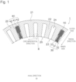
Fig. 1 is a schematic view of a cross section perpendicular to an axial direction of a stator of a first embodiment. -
Fig. 2 is an enlarged view of the stator of the first embodiment, and illustrates a cross section of a region II inFig. 1 . -
Fig. 3 is a schematic view illustrating a wedge insertion device of the first embodiment. -
Fig. 4 is a flowchart illustrating a method for manufacturing the stator of the first embodiment. -
Fig. 5 is a schematic view illustrating the method for manufacturing the stator of the first embodiment. -
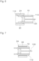
Fig. 6 is a schematic view illustrating the method for manufacturing the stator of the first embodiment. -
Fig. 7 is a schematic view illustrating the method for manufacturing the stator of the first embodiment. -
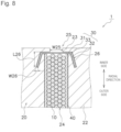
Fig. 8 is an enlarged view of a stator of a second embodiment, and corresponds toFig. 2 . -
Fig. 9 is an enlarged view of a stator of a third embodiment, and corresponds toFig. 2 . -
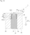
Fig. 10 is an enlarged view of a stator of a fourth embodiment, and corresponds toFig. 2 . -
Fig. 11 is an enlarged view of a stator of a comparative example, and corresponds toFig. 2 . - Hereinafter, embodiments of the present invention will be described with reference to the drawings. In the following drawings, an identical or corresponding component is denoted by an identical reference sign, and the description will not be repeated.
- In the following description, a direction in which the central axis of a
stator 1 extends, that is, a penetrating direction of aslot 24 is referred to as an "axial direction". One side along the axial direction is referred to as the lower side, and the other side is referred to as the upper side. The upward and downward direction is for use in specifying the positional relationship, and does not limit the actual direction. That is, a downward direction does not necessarily mean the direction of gravity. The axial direction is not particularly limited, and includes a vertical direction, a horizontal direction, a direction intersecting these directions, and the like. - Additionally, a direction orthogonal to the central axis of the
stator 1 is referred to as "radial direction". Moreover, a direction along an arc centered on the central axis of thestator 1 is referred to as "circumferential direction". - In addition, in the drawings used in the following description, a characteristic portion may be enlarged for the purpose of emphasizing the characteristic portion. Therefore, the dimensions and ratios of respective components are not necessarily the same as actual ones. Additionally, for the same purpose, less characteristic portions may be omitted from the drawings.
- As illustrated in
Fig. 1 , thestator 1 is a component of a motor and interacts with a rotor (not shown) to generate rotational torque. A distributed winding, in which acoil 10 is wound acrossseveral slots 24, is applied to thestator 1 of the present embodiment. Thestator 1 has thecoil 10, astator core 20, awedge 30, and aninsulating paper 40. - The
stator core 20 is formed in a hollow columnar shape. Thestator core 20 is formed by laminating thin silicon steel plates. Thestator core 20 includes acore back 21, a plurality ofteeth 22, and a plurality ofumbrella 23. - The
core back 21 is annular. Thecore back 21 of the present embodiment includes one member. That is, thecore back 21 is configured by one component instead of a plurality of components that can be divided in the circumferential direction. - The plurality of
teeth 22 extend from thecore back 21 in the radial direction. The plurality ofteeth 22 are disposed in the circumferential direction. - Specifically, the
teeth 22 extend radially inward from thecore back 21. Theteeth 22 are disposed at equal intervals in the circumferential direction in the inner end of thecore back 21 in the radial direction. Note that the circumferential width of theteeth 22 of the present embodiment is constant, but may not be constant. - The
slot 24 is provided between theteeth 22 adjacent to each other in the circumferential direction. Theslot 24 is a gap in the circumferential direction. - The plurality of
slots 24 penetrates in the axial direction. The circumferential width of theslot 24 increases radially outward. The circumferential width of theslot 24 of the present embodiment gradually increases radially outward. - The
slot 24 has a slot open 25 located at the inner end in the radial direction. The slot open 25 is smaller than the circumferential width of the space accommodating thecoil 10 in theslot 24. - The plurality of
umbrella 23 is located on both sides of theslot 24 in the circumferential direction and protrudes in the circumferential direction. Specifically, the plurality ofumbrella 23 are connected to the inner end of each of theteeth 22 in the radial direction and extends to both sides in the circumferential direction. That is, the circumferential width of theumbrella 23 is larger than the circumferential width of the inner end of theteeth 22 in the radial direction. The plurality ofumbrella 23 are disposed at equal intervals in the circumferential direction. When used in a motor, the plurality ofumbrella 23 face the rotor. - As illustrated in
Fig. 2 , thestator core 20 has agroove portion 26 provided at the end of each of theteeth 22 in the circumferential direction. Thegroove portion 26 penetrates in the axial direction. Thegroove portion 26 will be described later. - The
wedge 30 is disposed radially inward of theslot 24. Specifically, thewedge 30 is disposed between thecoil 10 inserted into theslot 24 and thestator core 20. InFig. 1 , thewedge 30 blocks the slot open 25. Thewedge 30 insulates thestator core 20 from thecoil 10. - The
wedge 30 contacts theumbrella 23. As a result, thewedge 30 can be easily inserted into theslot 24. - The
wedge 30 of the present embodiment has a U-shape as viewed in the axial direction. Specifically, thewedge 30 includes afirst shape portion 31, twosecond shape portions 32, and abent portion 33. - The
first shape portion 31 extends in the circumferential direction. Thefirst shape portion 31 is linear as viewed in the axial direction. As a result, thewedge 30 can be easily inserted into theslot 24. - The two
second shape portions 32 extend radially outward. Thesecond shape portion 32 is linear as viewed in the axial direction. - The
bent portion 33 connects both ends of thefirst shape portion 31 and the inner end of thesecond shape portion 32 in the radial direction. Thebent portion 33 is a bend corner of thewedge 30, and may be curved or sharp. - The
first shape portion 31, thesecond shape portion 32, and thebent portion 33 may be formed of one member, or different members may be connected to each other. - The insulating
paper 40 covers thecoil 10 inserted into theslot 24. The insulatingpaper 40 is disposed along theteeth 22 that define a space excluding the inner side of theslot 24 in the radial direction. The insulatingpaper 40 of the present embodiment has a U shape. Specifically, the insulatingpaper 40 includes acircumferential portion 41 extending in the circumferential direction and tworadial portions 42 extending radially inward from both ends of thecircumferential portion 41. InFig. 1 , the opening of the insulatingpaper 40 and the opening of thewedge 30 are in directions opposite to each other. - Here, the
groove portion 26 of thestator core 20 will be described mainly with reference toFig. 2. Fig. 2 is a schematic view of a state in which thewedge 30 and the insulatingpaper 40 are provided in oneslot 24 in the region II ofFig. 1 .Fig. 2 illustrates thegroove portion 26 in an exaggerated manner for the purpose of emphasizing the groove portion. - A part of the
wedge 30 is disposed in thegroove portion 26. Therefore, at the time of manufacturing thestator 1, a part of thewedge 30 can be held by thegroove portion 26 and inserted. Therefore, buckling of thewedge 30 can be suppressed. - The
groove portion 26 is a space for accommodating a part of thewedge 30. Thegroove portion 26 is a recess provided at the end of the teeth in the circumferential direction. - The
groove portion 26 is formed of a segment. The segment is a part of theteeth 22 and defines thegroove portion 26. - The
groove portion 26 is located at the inner end of thestator core 20 in the radial direction. Therefore, since thewedge 30 can be disposed at the inner end in the radial direction, the space factor of thecoil 10 can be improved. - In addition, the
groove portion 26 is located on the outer side of oneslot 24 in the circumferential direction. Thegroove portion 26 is located on the outer side in the circumferential direction of theumbrella 23 protruding from theteeth 22. - The
groove portion 26 of the present embodiment has a shape recessed radially outward. As a result, a part of thewedge 30 can be easily disposed in thegroove portion 26. InFig. 2 , thegroove portion 26 extends in the radial direction. - As viewed in the axial direction, a circumferential width W26 of the
groove portion 26 is smaller than a circumferential width W25 of the slot open 25. Accordingly, it is possible to suppress thecoil 10 from being disposed in thegroove portion 26. - As viewed in the axial direction, the circumferential length (circumferential width W) of the
groove portion 26 is smaller than a radial length L26 of thegroove portion 26. As a result, deterioration of magnetic characteristics due to thegroove portion 26 can be suppressed. - The circumferential width W26 of the
groove portion 26 is larger than the circumferential width of thesecond shape portion 32 of thewedge 30. The radial length L26 of thegroove portion 26 is longer than the radial length of thesecond shape portion 32 of thewedge 30. However, from the viewpoint of magnetic characteristics, thegroove portion 26 is preferably small. Therefore, the circumferential width W26 of thegroove portion 26 is more than 1 time and preferably 1.2 times or less the circumferential width of thesecond shape portion 32 of thewedge 30. The radial length L26 of thegroove portion 26 is more than 1 time and preferably 1.2 times or less the radial length of thesecond shape portion 32 of thewedge 30. - The
groove portion 26 is continuous with theslot 24. Thewedge 30 is accommodated in thegroove portion 26 and theslot 24. Here, a part of thewedge 30 is disposed in thegroove portion 26 and the rest of thewedge 30 is disposed in theslot 24. - Specifically, the
first shape portion 31 of thewedge 30 is disposed in theslot 24. Both ends of thefirst shape portion 31 in the circumferential direction may be disposed in theslot 24, or may be disposed in thegroove portion 26. Thesecond shape portion 32 of thewedge 30 is disposed in thegroove portion 26. Further, thebent portion 33 of thewedge 30 is disposed in thegroove portion 26. Accordingly, separation of thewedge 30 from thegroove portion 26 can be suppressed. - The
bent portion 33 may not be in contact with thegroove portion 26, but is in contact with the groove portion in the present embodiment. Thebent portion 33 may not be in contact with the side surface of theslot 24, but is in contact with the side surface in the present embodiment. Note thatFig. 2 illustrates the respective members separately without being in contact with each other. - A
wedge insertion device 200 will be described with reference toFigs. 1 to 3 . Note thatFig. 3 is a cross-sectional view schematically illustrating thewedge insertion device 200 by reducing the number of wedge guides 210 and the like. - As illustrated in
Fig. 3 , thewedge insertion device 200 inserts thewedge 30 disposed between thecoil 10 inserted into theslot 24 and thestator core 20 into theslot 24 penetrating thestator core 20 in the axial direction from one side to the other side in the axial direction. As described above, thestator core 20 has thegroove portions 26 provided at the end of theteeth 22 in the circumferential direction. Here, thewedge insertion device 200 inserts thewedge 30 into each of the plurality ofslots 24 of thestator core 20. - The
wedge insertion device 200 includes thewedge guide 210. Thewedge guide 210 guides thewedge 30 to theslot 24. Thewedge guide 210 is disposed on one side of thestator core 20 in the axial direction and extends in the axial direction. - The
wedge guide 210 of the present embodiment guides thewedge 30 to thegroove portion 26. The end surface in the axial direction of thewedge guide 210 in the axial direction has a shape corresponding to thegroove portion 26. As a result, the wedge guided by the wedge guide can be easily inserted into the groove portion. - Specifically, the end surface in the axial direction of the
wedge guide 210 in the axial direction has a shape that guides a part of thewedge 30 to thegroove portion 26 and guides the rest of thewedge 30 to theslot 24. - The
wedge insertion device 200 further includes an insertion member that inserts thewedge 30 into theslot 24. Thewedge insertion device 200 of the present embodiment further includes a wedge pusher (not illustrated) as an insertion member. - A method for manufacturing the
stator 1 of the present embodiment will be described with reference toFigs. 1 to 7 .Fig. 4 is a flowchart illustrating a method for manufacturing thestator 1 according to the present embodiment.Figs. 5 to 7 schematically illustrate a state in which acoil insertion device 100 including thewedge insertion device 200 is cut in the axial direction. Thecoil 10 is inserted into theslot 24 by thecoil insertion device 100 in the order ofFigs. 5 to 7 . - In the present embodiment, the
stator 1 is manufactured by inserting thecoil 10 into theslot 24 by thecoil insertion device 100 and inserting thewedge 30 into theslot 24 by thewedge insertion device 200 described above. - First, as illustrated in
Fig. 4 , anannular coil 10 is formed (step S1). In step S1, the coil wire is wound in an annular shape to form thecoil 10 having two coil side portions accommodated in theslot 24 and a coil crossing portion connecting the two coil side portions and disposed on both sides of thestator core 20 in the axial direction. - As illustrated in
Fig. 2 , thestator core 20 having thegroove portion 26 provided at the end of each of theteeth 22 in the circumferential direction is formed (step S2). - In the present embodiment, before the
coil 10 described later is inserted into theslot 24, the insulatingpaper 40 is disposed in theslot 24. - Next, the
coil 10 is inserted into the slot 24 (step S3). This step (S3) is performed as follows, for example. - Specifically, as illustrated in
Fig. 5 , theannular coil 10 formed in step (S1) is held by ablade 110 disposed radially inward of thestator core 20. Next, as illustrated inFigs. 6 and 7 , thecoil 10 is moved in the axial direction by astripper 120 as a coil moving mechanism disposed radially inward of theblade 110. Specifically, thestripper 120 is moved from one side to the other side in the axial direction. As a result, the two coil side portions of thecoil 10 are disposed in theslot 24, the coil crossing portion on one side in the axial direction straddles between theslots 24 on one side of thestator core 20, and the coil crossing portion on the other side straddles between theslots 24 on the other side of thestator core 20. - In addition, the
wedge 30 is disposed in at least oneslot 24 and onegroove portion 26 between theteeth 22 adjacent in the circumferential direction (step S4). In step S5, as illustrated inFig. 3 , thewedge guide 210 is used to guide thewedge 30 to thegroove portion 26 and theslot 24. Then, thewedge 30 is moved in the axial direction using the wedge pusher. Specifically, the wedge pusher is moved from one side to the other side in the axial direction. As a result, a part of thewedge 30 can be inserted into thegroove portion 26, and the rest of thewedge 30 can be inserted into theslot 24. As a result, thewedge 30 can be disposed between thecoil 10 and theslot 24. Therefore, thewedge 30 can close the slot open 25. - By performing the above steps (steps S1 to S4), the
stator 1 illustrated inFigs. 1 and2 can be manufactured. - Next, operations and effects of the
stator 1 of the present embodiment will be described in comparison with astator 2 of a comparative example ofFig. 11. Fig. 11 is an enlarged schematic view illustrating thestator 2 of the comparative example and corresponds toFig. 2 . - As illustrated in
Fig. 11 , thestator core 20 of thestator 2 of the comparative example does not include thegroove portion 26 of the present embodiment.
Therefore, when thewedge 30 is inserted into theslot 24, thecoil 10 previously inserted into theslot 24 pushes thewedge 30. Therefore, thewedge 30 may be inserted at a position different from the target position in theslot 24. This may cause thewedge 30 to buckle as thewedge 30 is moved from one side to the other side in theslot 24 in the axial direction. - On the other hand, as illustrated in
Fig. 2 , thestator core 20 of thestator 1 of the present embodiment is provided with agroove portion 26 for inserting thewedge 30. Therefore, at the time of manufacturing thestator 1, thewedge 30 can be inserted into theslot 24 in a state where thegroove portion 26 holds thewedge 30. That is, theteeth 22 defining thegroove portion 26 can protect thewedge 30 from the pressing of thecoil 10. Therefore, buckling of thewedge 30 can be suppressed. - Further, since the
groove portion 26 can hold a part of thewedge 30, insertion and arrangement of thewedge 30 into theslot 24 are easy. - The stator of a second embodiment illustrated in
Fig. 8 basically has the same configuration as thestator 1 illustrated inFig. 2 , but differs in the shape of the groove portion.Fig. 8 is an enlarged schematic view illustrating thestator 1 of the second embodiment and corresponds toFig. 2 . - The
groove portion 26 of the first embodiment illustrated inFig. 2 has a shape extending along the radial direction, but thegroove portion 26 of the second embodiment illustrated inFig. 8 is different in having a shape extending to the outer side in the circumferential direction. - The stator of a third embodiment illustrated in
Fig. 9 basically has the same configuration as thestator 1 illustrated inFig. 2 , but differs in the shape of the groove portion.Fig. 9 is an enlarged schematic view illustrating thestator 1 of the third embodiment and corresponds toFig. 2 . - The
groove portion 26 of the first embodiment illustrated inFig. 2 is separated from theslot 24, but thegroove portion 26 of the third embodiment illustrated inFig. 9 is different in being integrated with theslot 24. - The stator of a fourth embodiment illustrated in
Fig. 10 basically has the same configuration as thestator 1 illustrated inFig. 2 , but differs in the shape of the groove portion.Fig. 10 is an enlarged schematic view illustrating thestator 1 of the fourth embodiment and corresponds toFig. 2 . - The
groove portion 26 of the first embodiment illustrated inFig. 2 is defined by a portion extending in the radial direction of theteeth 22, but thegroove portion 26 of the fourth embodiment illustrated inFig. 10 is different in that it is defined by aprotrusion 22a further extending to the outer side in the circumferential direction. - Specifically, the
teeth 22 of the present embodiment have theprotrusion 22a that defines thegroove portion 26 and extends in the circumferential direction. As a result, deterioration of magnetic characteristics due to thegroove portion 26 can be suppressed. - In
Fig. 10 , theprotrusion 22a extending in the circumferential direction and aprotrusion 22b extending in the radial direction are provided in theslot 24 of the first embodiment. Theprotrusion 22a and theprotrusion 22b define thegroove portion 26 and are integrated. - A circumferential width W22a of the
protrusion 22a is equal to or less than a circumferential width W23 protruding from theteeth 22 in theumbrella 23, and is preferably smaller than the circumferential width W23. In this case, it is possible to suppress theprotrusion 22a from hindering the insertion of thecoil 10 into theslot 24. - The
protrusion 22a may be disposed in the entire axial direction of thestator core 20, but is preferably disposed only at the end on one side of thestator core 20 in the axial direction. That is, theprotrusion 22a is preferably not disposed at the other end of thestator core 20 in the axial direction. In this case, thegroove portion 26 can hold thewedge 30 at the one-side end in the axial direction and prevent the insertion of thecoil 10 from being hindered at portions other than the one-side end in the axial direction. - The shape of the
groove portion 26 of the present invention is not limited to the shape of thegroove portion 26 of the first to fourth embodiments described above as long as a part of thewedge 30 is disposed. - In the first to fourth embodiments described above, the
stator core 20 has thegroove portion 26 having the same shape, but the present invention is not limited thereto. The stator core of the present invention may have two or more kinds of groove portions of the first to fourth embodiments. - In the above-described embodiment, as illustrated in
Fig. 1 , the twoslots 24 into which the coil is inserted are oneslot 24 and anotherslot 24 sandwiching the fourslots 24. However, the present invention is not limited to this. - In the above-described embodiment, the method for inserting one
coil 10 into twoslots 24 has been described as an example. A plurality ofcoils 10 may be simultaneously inserted into four ormore slots 24. - The embodiments disclosed herein should be considered as an example in all points and not restrictive. The scope of the present invention is shown not by the embodiments described above but by the claims, and it is intended that all modifications within the meaning and scope equivalent to the scope of the claims are included.
-
- 1
- stator
- 10
- coil
- 20
- stator core
- 21
- core back
- 22
- teeth
- 22a
- protrusion
- 23
- umbrella
- 24
- slot
- 26
- groove portion
- 30
- wedge
- 31
- first shape portion
- 32
- second shape portion
- 33
- bent portion
- 200
- wedge insertion device
- 210
- wedge guide
Claims (11)
- A stator (1) comprising:a stator core (20) including a plurality of teeth (22) disposed in a circumferential direction and a plurality of slots (24) provided between the teeth (22) and penetrating in an axial direction; anda wedge (30) disposed radially inward of the slot (24), whereinthe stator core (20) includes a groove portion (26) provided at an end of each of the teeth (22) in a circumferential direction, anda part of the wedge (30) is disposed in the groove portion (26).
- The stator (1) according to claim 1, whereinthe slot (24) has a slot open (25) located at an inner end in a radial direction, anda circumferential width of the groove portion (26) is smaller than a circumferential width of the slot open (25) as viewed in an axial direction.
- The stator (1) according to claim 1 or 2, wherein a circumferential length of the groove portion (26) is smaller than a radial length of the groove portion (26) as viewed in an axial direction.
- The stator (1) according to any one of claims 1 to 3, whereinthe stator core (20) further includes an umbrella (23) positioned on both sides of the slot (24) in a circumferential direction and protruding in a circumferential direction, andthe wedge (30) is brought into contact with the umbrella (23).
- The stator (1) according to any one of claims 1 to 4, wherein the groove portion (26) has a shape recessed radially outward.
- The stator (1) according to any one of claims 1 to 5, whereinthe wedge (30) includes:a first shape portion (31) extending in a circumferential direction;two second shape portions (32) extending radially outward; anda bent portion (33) connecting both ends of the first shape portion (31) in a circumferential direction and an inner end of the second shape portion (32) in a radial direction, andthe bent portion (33) is disposed in the groove portion (26).
- The stator (1) according to claim 6, wherein the first shape portion (31) is linear as viewed in an axial direction.
- The stator (1) according to any one of claims 1 to 7, wherein the teeth (22) each have a protrusion (22a) defining the groove portion (26) and extending in a circumferential direction.
- The stator (1) according to claim 8, whereinthe stator core (20) further includes an umbrella (23) positioned on both sides of the slot (24) in a circumferential direction and protruding in a circumferential direction, anda circumferential width of the protrusion (22a) is smaller than a circumferential width protruding from the teeth (22) in the umbrella (23).
- The stator (1) according to claim 8 or 9, wherein the protrusion (22a) is disposed only at an end on one side in an axial direction of the stator core (20).
- A wedge insertion device (200) that inserts a wedge (30) disposed between a coil (10) inserted into a slot (24) from one side to another side in an axial direction and a stator core (20), the slot (24) penetrating the stator core (20) in an axial direction thereof, whereinthe stator core (20) includes a groove portion (26) provided at an end of each of the teeth (22) in a circumferential direction,the wedge insertion device (200) comprises a wedge guide (210) that is disposed on one side in an axial direction of the stator core (20), extends in the axial direction, and guides the wedge (30) to the groove portion (26), andan end surface on another side in the axial direction of the wedge guide (210) has a shape corresponding to the groove portion (26).
Applications Claiming Priority (1)
| Application Number | Priority Date | Filing Date | Title |
|---|---|---|---|
| JP2022054233A JP2023146831A (en) | 2022-03-29 | 2022-03-29 | Stator and wedge insertion device |
Publications (1)
| Publication Number | Publication Date |
|---|---|
| EP4254747A1 true EP4254747A1 (en) | 2023-10-04 |
Family
ID=85778740
Family Applications (1)
| Application Number | Title | Priority Date | Filing Date |
|---|---|---|---|
| EP23164530.0A Withdrawn EP4254747A1 (en) | 2022-03-29 | 2023-03-28 | Stator and wedge insertion device |
Country Status (4)
| Country | Link |
|---|---|
| US (1) | US20230318386A1 (en) |
| EP (1) | EP4254747A1 (en) |
| JP (1) | JP2023146831A (en) |
| CN (1) | CN116896176A (en) |
Families Citing this family (4)
| Publication number | Priority date | Publication date | Assignee | Title |
|---|---|---|---|---|
| CN209389795U (en) * | 2019-02-26 | 2019-09-13 | 上海磁雷革传动系统有限公司 | A stator core assembly and motor and vehicle having the same |
| US12176756B2 (en) * | 2020-01-21 | 2024-12-24 | Mitsubishi Electric Corporation | Stator with stator magnet, magnetic body, fixing member, and coil disposed in slots and rotary electric machine using same |
| EP4096070A4 (en) * | 2020-01-21 | 2023-01-18 | Mitsubishi Electric Corporation | STATOR AND ROTATING ELECTRIC MACHINE USING IT |
| DE102020121057A1 (en) * | 2020-08-11 | 2022-02-17 | Schaeffler Technologies AG & Co. KG | Coil component with closure element without direct contact with carrier; and electric machine |
Citations (5)
| Publication number | Priority date | Publication date | Assignee | Title |
|---|---|---|---|---|
| US3447225A (en) * | 1966-07-08 | 1969-06-03 | Fort Wayne Tool & Die Inc | Apparatus and method for inserting dynamoelectric machine coils and slot wedges |
| JPS4848119U (en) * | 1971-10-06 | 1973-06-23 | ||
| JPS6051427A (en) * | 1983-08-26 | 1985-03-22 | Hitachi Ltd | Magnetic wedge of rotating electric machine |
| JP2011200107A (en) | 2010-02-26 | 2011-10-06 | E−Tec株式会社 | Coil insertion method, and coil insertion apparatus |
| JP2014158316A (en) * | 2013-02-14 | 2014-08-28 | Toshiba Mitsubishi-Electric Industrial System Corp | Stator of rotary electric machine |
Family Cites Families (9)
| Publication number | Priority date | Publication date | Assignee | Title |
|---|---|---|---|---|
| US3940647A (en) * | 1974-11-27 | 1976-02-24 | Allis-Chalmers Corporation | Slot closure for dynamoelectric machine |
| CH579844A5 (en) * | 1974-12-04 | 1976-09-15 | Bbc Brown Boveri & Cie | |
| US4147946A (en) * | 1977-05-31 | 1979-04-03 | Sundstrand Corporation | Rotor structure for an electric machine |
| US4486506A (en) * | 1981-10-16 | 1984-12-04 | Tokyo Shibaura Denki Kabushiki Kaisha | Solid insulator and electric equipment coil using the same |
| US5239220A (en) * | 1990-04-26 | 1993-08-24 | Mitsubishi Denki K.K. | Stator wedge and guide jig therefor |
| JP2005184994A (en) * | 2003-12-19 | 2005-07-07 | Matsushita Electric Ind Co Ltd | Electric motor and its production method |
| JP4476290B2 (en) * | 2004-07-14 | 2010-06-09 | 三菱電機株式会社 | Rotating electric machine stator |
| EP2933901B1 (en) * | 2014-04-15 | 2016-10-26 | Siemens Aktiengesellschaft | Stator of an electric machine and production thereof |
| WO2016021070A1 (en) * | 2014-08-08 | 2016-02-11 | 三菱電機株式会社 | Alternating-current motor |
-
2022
- 2022-03-29 JP JP2022054233A patent/JP2023146831A/en active Pending
-
2023
- 2023-03-20 US US18/123,367 patent/US20230318386A1/en not_active Abandoned
- 2023-03-28 EP EP23164530.0A patent/EP4254747A1/en not_active Withdrawn
- 2023-03-28 CN CN202310314337.9A patent/CN116896176A/en active Pending
Patent Citations (5)
| Publication number | Priority date | Publication date | Assignee | Title |
|---|---|---|---|---|
| US3447225A (en) * | 1966-07-08 | 1969-06-03 | Fort Wayne Tool & Die Inc | Apparatus and method for inserting dynamoelectric machine coils and slot wedges |
| JPS4848119U (en) * | 1971-10-06 | 1973-06-23 | ||
| JPS6051427A (en) * | 1983-08-26 | 1985-03-22 | Hitachi Ltd | Magnetic wedge of rotating electric machine |
| JP2011200107A (en) | 2010-02-26 | 2011-10-06 | E−Tec株式会社 | Coil insertion method, and coil insertion apparatus |
| JP2014158316A (en) * | 2013-02-14 | 2014-08-28 | Toshiba Mitsubishi-Electric Industrial System Corp | Stator of rotary electric machine |
Also Published As
| Publication number | Publication date |
|---|---|
| JP2023146831A (en) | 2023-10-12 |
| US20230318386A1 (en) | 2023-10-05 |
| CN116896176A (en) | 2023-10-17 |
Similar Documents
| Publication | Publication Date | Title |
|---|---|---|
| US20230318386A1 (en) | Stator and wedge insertion device | |
| EP3109981B1 (en) | Stator assembly method and stator assembly device | |
| EP3211772B1 (en) | Stator production method and coil | |
| JP6358086B2 (en) | Stator assembly apparatus and stator assembly method | |
| EP3476021B1 (en) | Stator and motor having the same | |
| US9502939B2 (en) | Method for manufacturing an armature core | |
| CN103460570B (en) | Key insertion machine and coil inserting device | |
| JP2013223396A (en) | Method for manufacturing stator, and insulation paper | |
| EP1401085A2 (en) | Insulation of winding heads of electrical machines | |
| US6744168B2 (en) | Stator and stator manufacturing method | |
| CN105210276A (en) | Coil insertion machine | |
| EP4459841A1 (en) | Stator core, stator, method for manufacturing stator core, and method for manufacturing stator | |
| JP2013162562A (en) | Rotary electric machine and manufacturing method of the same | |
| CN116896235A (en) | wedge insertion device | |
| JP7847961B2 (en) | Coil insertion device | |
| JP7487697B2 (en) | Manufacturing method of the stator | |
| JP2008079485A (en) | Stator for rotating electric machine and method for manufacturing the same | |
| CN115133730A (en) | Coil insertion device | |
| JP2023146830A (en) | wedge insertion device | |
| JPH08275471A (en) | Electric motor stator | |
| JP2023111705A (en) | Wedge insertion device and coil insertion device | |
| JP2017085795A (en) | Stator manufacturing method |
Legal Events
| Date | Code | Title | Description |
|---|---|---|---|
| PUAI | Public reference made under article 153(3) epc to a published international application that has entered the european phase |
Free format text: ORIGINAL CODE: 0009012 |
|
| STAA | Information on the status of an ep patent application or granted ep patent |
Free format text: STATUS: THE APPLICATION HAS BEEN PUBLISHED |
|
| AK | Designated contracting states |
Kind code of ref document: A1 Designated state(s): AL AT BE BG CH CY CZ DE DK EE ES FI FR GB GR HR HU IE IS IT LI LT LU LV MC ME MK MT NL NO PL PT RO RS SE SI SK SM TR |
|
| STAA | Information on the status of an ep patent application or granted ep patent |
Free format text: STATUS: REQUEST FOR EXAMINATION WAS MADE |
|
| 17P | Request for examination filed |
Effective date: 20240326 |
|
| RBV | Designated contracting states (corrected) |
Designated state(s): AL AT BE BG CH CY CZ DE DK EE ES FI FR GB GR HR HU IE IS IT LI LT LU LV MC ME MK MT NL NO PL PT RO RS SE SI SK SM TR |
|
| STAA | Information on the status of an ep patent application or granted ep patent |
Free format text: STATUS: EXAMINATION IS IN PROGRESS |
|
| 17Q | First examination report despatched |
Effective date: 20250402 |
|
| STAA | Information on the status of an ep patent application or granted ep patent |
Free format text: STATUS: THE APPLICATION IS DEEMED TO BE WITHDRAWN |
|
| 18D | Application deemed to be withdrawn |
Effective date: 20250805 |