EP4254740A1 - Inverter-integrated motor - Google Patents
Inverter-integrated motor Download PDFInfo
- Publication number
- EP4254740A1 EP4254740A1 EP20963399.9A EP20963399A EP4254740A1 EP 4254740 A1 EP4254740 A1 EP 4254740A1 EP 20963399 A EP20963399 A EP 20963399A EP 4254740 A1 EP4254740 A1 EP 4254740A1
- Authority
- EP
- European Patent Office
- Prior art keywords
- motor
- inverter
- power module
- disposed
- rotation shaft
- Prior art date
- Legal status (The legal status is an assumption and is not a legal conclusion. Google has not performed a legal analysis and makes no representation as to the accuracy of the status listed.)
- Pending
Links
Images


Classifications
-
- H—ELECTRICITY
- H02—GENERATION; CONVERSION OR DISTRIBUTION OF ELECTRIC POWER
- H02K—DYNAMO-ELECTRIC MACHINES
- H02K11/00—Structural association of dynamo-electric machines with electric components or with devices for shielding, monitoring or protection
- H02K11/30—Structural association with control circuits or drive circuits
- H02K11/33—Drive circuits, e.g. power electronics
-
- H—ELECTRICITY
- H02—GENERATION; CONVERSION OR DISTRIBUTION OF ELECTRIC POWER
- H02K—DYNAMO-ELECTRIC MACHINES
- H02K11/00—Structural association of dynamo-electric machines with electric components or with devices for shielding, monitoring or protection
- H02K11/20—Structural association of dynamo-electric machines with electric components or with devices for shielding, monitoring or protection for measuring, monitoring, testing, protecting or switching
- H02K11/27—Devices for sensing current, or actuated thereby
-
- H—ELECTRICITY
- H02—GENERATION; CONVERSION OR DISTRIBUTION OF ELECTRIC POWER
- H02K—DYNAMO-ELECTRIC MACHINES
- H02K3/00—Details of windings
- H02K3/46—Fastening of windings on the stator or rotor structure
- H02K3/50—Fastening of winding heads, equalising connectors, or connections thereto
-
- H—ELECTRICITY
- H02—GENERATION; CONVERSION OR DISTRIBUTION OF ELECTRIC POWER
- H02K—DYNAMO-ELECTRIC MACHINES
- H02K3/00—Details of windings
- H02K3/46—Fastening of windings on the stator or rotor structure
- H02K3/52—Fastening salient pole windings or connections thereto
- H02K3/521—Fastening salient pole windings or connections thereto applicable to stators only
-
- H—ELECTRICITY
- H02—GENERATION; CONVERSION OR DISTRIBUTION OF ELECTRIC POWER
- H02K—DYNAMO-ELECTRIC MACHINES
- H02K5/00—Casings; Enclosures; Supports
- H02K5/04—Casings or enclosures characterised by the shape, form or construction thereof
- H02K5/20—Casings or enclosures characterised by the shape, form or construction thereof with channels or ducts for flow of cooling medium
-
- H—ELECTRICITY
- H02—GENERATION; CONVERSION OR DISTRIBUTION OF ELECTRIC POWER
- H02K—DYNAMO-ELECTRIC MACHINES
- H02K2203/00—Specific aspects not provided for in the other groups of this subclass relating to the windings
- H02K2203/03—Machines characterised by the wiring boards, i.e. printed circuit boards or similar structures for connecting the winding terminations
-
- H—ELECTRICITY
- H02—GENERATION; CONVERSION OR DISTRIBUTION OF ELECTRIC POWER
- H02K—DYNAMO-ELECTRIC MACHINES
- H02K2203/00—Specific aspects not provided for in the other groups of this subclass relating to the windings
- H02K2203/09—Machines characterised by wiring elements other than wires, e.g. bus rings, for connecting the winding terminations
-
- H—ELECTRICITY
- H02—GENERATION; CONVERSION OR DISTRIBUTION OF ELECTRIC POWER
- H02K—DYNAMO-ELECTRIC MACHINES
- H02K2211/00—Specific aspects not provided for in the other groups of this subclass relating to measuring or protective devices or electric components
- H02K2211/03—Machines characterised by circuit boards, e.g. pcb
Definitions
- the present invention relates to an inverter-integrated motor.
- An inverter-integrated motor in which a motor and an inverter are integrally formed is known.
- JP2015-089298A discloses an inverter-integrated motor in which an inverter is provided in the vicinity of a motor, and a motor case and an inverter case are disposed adjacent to each other in an axial direction.
- a motor coil wire that electrically connects a motor and an inverter is disposed on an outer peripheral side of the inverter, and components of the inverter are disposed inside the bus bar.
- the components of the inverter are restricted in size. For example, when output and withstand voltage of the inverter are increased in order to increase output of the motor, the components are increased in size, but the components cannot be expanded in a radial direction due to the presence of the bus bar, and are expanded in a rotation shaft direction. Therefore, there is a problem that it is difficult to reduce the size of the components in the rotation shaft direction when the output of the motor is increased.
- the present invention is made in view of such a problem, and an object of the present invention is to provide an inverter-integrated motor that can be decreased in size in a rotation shaft direction even when output of a motor is increased.
- an inverter unit at an end portion of a motor in a rotation shaft direction the motor includes a conductive member electrically connected to the inverter unit, the inverter unit includes a control component connected to the conductive member and configured to control driving of the motor, the conductive member extends from the end portion of the motor along a rotation shaft of the motor in a state of being adjacent to the rotation shaft, and the control component is disposed on a radially outer side of the conductive member.
- a conductive member connecting the motor and an inverter is disposed adjacent to a rotation shaft, and a control component of an inverter unit is disposed on a radially outer side of the conductive member, and thus the control component can be expanded toward the radially outer side.
- a control component of an inverter unit is disposed on a radially outer side of the conductive member, and thus the control component can be expanded toward the radially outer side.
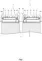
- FIGS. 1 and 2 are diagrams illustrating an inverter-integrated motor 1 according to an embodiment of the present invention.
- FIG. 1 is a cross-sectional view in a rotation shaft direction
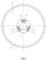
- FIG. 2 is a cross-sectional view taken along a line II-II in FIG. 1 .
- the inverter-integrated motor 1 includes a motor 3 and an inverter unit 2 disposed at an axial end portion (coil end) of the motor 3.
- the inverter-integrated motor 1 is mounted on, for example, a vehicle, and drives the vehicle by rotation of the motor 3.
- the motor 3 includes a rotation shaft 11, and a rotor and a stator (not shown).
- the motor 3 rotates the rotor by being supplied with electric power from the inverter unit 2, and rotationally drives the rotation shaft 11.
- the inverter unit 2 converts DC power supplied from a battery (not shown) into AC power, and supplies the AC power to the motor 3 to drive the motor 3. In addition, during deceleration of the vehicle, the battery is charged with regenerated electric power of the motor 3.
- the inverter unit 2 includes a case 20 and control components (smoothing capacitor 21, power module 22, control board 23, current sensor 24, and the like) accommodated in the case 20.
- the case 20 of the inverter unit 2 has a cylindrical outer periphery along an outer periphery of the motor 3.
- the rotation shaft 11 of the motor 3 passes through an inner peripheral side of the case 20. Therefore, the case 20 is formed in an annular shape (doughnut shape).
- the smoothing capacitor 21 smoothes noise and ripples in a direct current to be supplied to the power module 22.
- the smoothing capacitor 21 is formed by accommodating a plurality of capacitor elements formed of, for example, film capacitors.
- the power module 22 converts the DC power supplied from the battery into three-phase high frequency electric power of U, V, and W, and supplies the three-phase high frequency electric power to the motor 3 via the bus bars 30.
- the power module 22 includes a plurality of switching elements corresponding to each of the three phases.
- the power module 22 is provided with a cooler such as a heat dissipation fin for cooling the switching elements.
- the power module 22 is provided with a motor-side bus bar 221 and a capacitor-side bus bar 222.
- the motor-side bus bar 221 is coupled to the bus bar 30 of the motor 3 by bolting, welding, or the like, and outputs an AC power to the bus bar 30.
- the capacitor-side bus bar 222 is coupled to a terminal of the smoothing capacitor 21 by bolting, welding, or the like.
- the capacitor-side bus bar 222 is also connected to the battery (not shown) and supplied with the DC power.
- the control board 23 receives an instruction from a vehicle control unit (not shown), controls an operation of the power module 22 to adjust electric power to be supplied to the motor 3.
- the control board 23 is electrically connected with the power module 22 and the current sensor 24.
- the control board 23 acquires a current value in the bus bar 30 acquired by the current sensor 24, and outputs a control signal to the switching elements of the power module 22.
- a microcomputer and various electric components are mounted on the control board 23.
- the current sensor 24 is provided on the bus bar 30, acquires a current value of a current to be supplied to the motor 3, and outputs a signal corresponding to the acquired current value to the control board 23.
- the current sensor 24 includes, for example, a hall element that detects a current, and the hall element detects a current value of a current flowing through the bus bar 30.
- a bus bar extends in an axial direction from the vicinity of an outer periphery of an end portion of the motor, and the bus bar is provided with a current sensor.
- the bus bars 30 are disposed upright at the axial end portion, that is, on a side at which the inverter unit 2 is disposed. As shown in FIG. 2 , there are three bus bars 30 corresponding to three phases of U, V, and W. The bus bars 30 are arranged close to and at equal intervals around the rotation shaft 11, and extend in the axial direction along the rotation shaft 11 from the end portion of the motor 3.
- current sensors 24 are provided in the vicinity of portions of the bus bars 30 that are drawn out from the motor 3, respectively.
- Each of the current sensors 24 is disposed along an extending direction of the bus bar 30 so as to surround the bus bar 30, and detects a current value of a current flowing through the bus bar 30.
- the current sensor 24 is connected to the control board 23 by a harness or the like, and outputs a signal indicating the current value to the control board 23.
- the smoothing capacitor 21 is disposed on an outer peripheral side of the bus bars 30 and the current sensors 24. As shown in FIG. 2 , the smoothing capacitor 21 has a substantially annular cross section when viewed in the axial direction.
- the power module 22 and the control board 23 are similarly formed in an annular shape.
- the inverter unit 2 is disposed by stacking the smoothing capacitor 21, the power module 22, and the control board 23 in this order from the end portion of the motor 3.
- the bus bar 30 extending from the end portion of the motor 3 and the current sensor 24 disposed along the bus bar 30 are located in a hollow portion of an inner periphery of the smoothing capacitor 21, the power module 22, and the control board 23.
- the smoothing capacitor 21, the power module 22, and the control board 23, which are control components of the inverter unit 2 are less restricted in size on an outer peripheral side thereof. That is, it is possible to expand the control components to a size that can be accommodated in the case 20 (about an outer diameter of the motor 3).
- the size of the control components can be increased in the radial direction, the number and the size of the capacitor elements accommodated in the smoothing capacitor 21 can be increased.
- the switching elements can be increased in size, and a wiring connected to a power element can be enlarged. Further, the cooler that cools the switching elements can be increased in size.
- mounted elements and wirings can also be enlarged.
- control components of the inverter unit 2 are increased in size in accordance with the increase in the output of the motor 3, the control components can be expanded in an outer diameter direction, and can be prevented from being expanded in the rotation shaft direction as much as possible.
- the embodiment of the present invention described above is applied to the inverter-integrated motor 1 including the inverter unit 2 at the end portion of the motor 3 in a rotation shaft 11 direction.
- the motor 3 includes the bus bars 30 as conductive members electrically connected to the inverter unit 2.
- the inverter unit 2 includes the control components that are connected to the bus bars 30 and that control the driving of the motor 3.
- the bus bars 30 are provided around the rotation shaft 11, adjacent to the rotation shaft 11, and extend along the rotation shaft 11.
- the control components are disposed on a radially outer side of the bus bar 30.
- the control components of the inverter unit 2 are increased in size due to the increase of withstand voltage and output in order to increase the output of the motor 3, the control components can be expanded in the radial direction, and thus can be prevented from being expanded in the rotation shaft direction. Therefore, even when the output of the motor 3 is increased, the inverter-integrated motor 1 can be decreased in size in the rotation shaft direction.
- the current sensor 24 is disposed on the bus bar 30, and the control components including the power module 22 that supplies electric power to the motor 3, the smoothing capacitor 21 that smoothes a current of the power module 22, and the control board 23 that controls the operation of the power module 22, are disposed around the bus bars 30 and the current sensors 24.
- the power module 22, the smoothing capacitor 21, and the control board 23, which are control components of the inverter unit 2 are disposed outside the bus bars 30 and the current sensors 24, so that these control components can be expanded in the radial direction.
- control components are disposed by stacking the smoothing capacitor 21, the power module 22, and the control board 23 in this order from the end portion of the motor 3.
- the current sensor 24 disposed on the bus bar 30 and the motor-side bus bar 221 of the power module 22 can be disposed so as not to interfere with each other, so that these control components can be expanded in the radial direction.
- FIG. 3 is a diagram illustrating the inverter-integrated motor 1 according to the modification of the present invention, and is a cross-sectional view in the rotation shaft direction.
- the inverter unit 2 is disposed by stacking the control board 23, the power module 22, and the smoothing capacitor 21 in this order from the end portion of the motor 3.
- the bus bars 30 are disposed on an inner periphery of the inverter unit 2, so that the control components of the inverter unit 2 can also be expanded in the radial direction even when the control components are increased in size due to the increase of the withstand voltage and the output in order to increase the output of the motor 3.
- the smoothing capacitor 21 when the smoothing capacitor 21 is disposed on a side separated from the motor 3, interference with the bus bar 30 can be avoided on an inner periphery of the smoothing capacitor 21, and thus a shape of the smoothing capacitor 21 can be expanded to an inner peripheral side as well.
- the control board 23 when the control board 23 is close to the motor 3, the control board 23 may be affected by noise caused by driving of the motor 3. In order to prevent this, it is desirable to provide a shielding member that shields electromagnetic waves or the like between the control board 23 and the motor 3.
- FIG. 4 is a diagram illustrating the inverter-integrated motor 1 according to another modification of the present invention, and is a cross-sectional view in the rotation shaft direction.
- the current sensor 24 is mounted on the control board 23. More specifically, the current sensor 24 is formed such that a hall element that detects a current is accommodated in a case. A terminal extending from the hall element is fixed on the control board 23. That is, the control board 23 is disposed on the radially outer side of the hall element that detects the current.
- FIG. 5 is a diagram illustrating the inverter-integrated motor 1 according to still another modification of the present invention, and is a cross-sectional view in the rotation shaft direction.
- the inverter unit 2 is disposed by stacking the power module 22, the control board 23, and the smoothing capacitor 21 in this order from the end portion of the motor 3.
- control components of the inverter unit 2 can be expanded in the radial direction even when the control components are increased in size due to the increase of the withstand voltage and the output in order to increase the output of the motor 3.
- the cooling of the power module 22 can be shared with the cooling of the motor 3.
- a housing (or coil end) of the motor 3 is formed with a refrigerant flow path 3a through which a refrigerant flows. Therefore, by bringing the power module 22 and the refrigerant flow path 3a on the end portion side of the motor 3 close to each other, the switching elements of the power module 22 can be cooled by the refrigerant in the refrigerant flow path 3a.
- the power module 22 can have a higher withstand voltage.
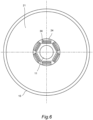
- FIG. 6 is a diagram illustrating the inverter-integrated motor 1 according to still another modification of the present invention, and is a diagram corresponding to the cross-sectional view taken the line II-II in FIG. 2 .
- the modification shown in FIG. 6 is a modification of the configurations described with reference to FIGS. 1 to 5 , and is different in a configuration of the bus bar 30 protruding from the motor 3. Since other configurations are the same as those in FIG. 2 , the same reference numerals are given thereto, and the description thereof will be omitted.
- the motor 3 includes six bus bars 30. Regarding these bus bars 30, two bus bars 30 are provided for each of the U phase, the V phase, and the W phase. Each bus bar 30 is provided with the current sensor 24. Accordingly, the bus bar 30 can be freely formed in accordance with a configuration of the motor 3.
- the bus bars 30 are disposed on the inner periphery of the inverter unit 2, so that the control components of the inverter unit 2 can be expanded in the radial direction even when the control components are increased in size due to the increase of the withstand voltage and the output in order to increase the output of the motor 3.
- the current sensor 24 is disposed on the bus bar 30 in the vicinity of the end portion of the motor 3, and the present invention is not limited to this configuration.
- the current sensor 24 may be disposed on the bus bar 30 at a position separated from the motor 3, and the inner peripheral side of the smoothing capacitor 21 (or another control component) may be close to the bus bar 30 on the end portion side of the motor 3 with respect to the current sensor 24.
- the inverter-integrated motor 1 may be mounted on an electric vehicle that travels by driving the inverter-integrated motor 1 with electric power of a battery mounted on the vehicle, or may be mounted on a series hybrid vehicle that includes an engine and that drives the inverter-integrated motor 1 with electric power generated by the engine. Alternatively, the inverter-integrated motor 1 may be used as another driving force source.
- the smoothing capacitor 21, the power module 22, and the control board 23, which are control components of the inverter unit 2 have an annular shape, and the present invention is not limited thereto.
- the control components may have any shape, and the shape may be a polygon or a combination of a curved surface and a polygon.
- the control components may have any shape as long as it corresponds to shapes of an element, a wiring, and the like constituting each component.
Landscapes
- Engineering & Computer Science (AREA)
- Power Engineering (AREA)
- Microelectronics & Electronic Packaging (AREA)
- Inverter Devices (AREA)
- Centrifugal Separators (AREA)
Abstract
Description
- The present invention relates to an inverter-integrated motor.
- An inverter-integrated motor in which a motor and an inverter are integrally formed is known.
-
JP2015-089298A - In the related art, a motor coil wire (bus bar) that electrically connects a motor and an inverter is disposed on an outer peripheral side of the inverter, and components of the inverter are disposed inside the bus bar. With such a configuration, the components of the inverter are restricted in size. For example, when output and withstand voltage of the inverter are increased in order to increase output of the motor, the components are increased in size, but the components cannot be expanded in a radial direction due to the presence of the bus bar, and are expanded in a rotation shaft direction. Therefore, there is a problem that it is difficult to reduce the size of the components in the rotation shaft direction when the output of the motor is increased.
- The present invention is made in view of such a problem, and an object of the present invention is to provide an inverter-integrated motor that can be decreased in size in a rotation shaft direction even when output of a motor is increased.
- According to an aspect of the present invention, an inverter unit at an end portion of a motor in a rotation shaft direction, the motor includes a conductive member electrically connected to the inverter unit, the inverter unit includes a control component connected to the conductive member and configured to control driving of the motor, the conductive member extends from the end portion of the motor along a rotation shaft of the motor in a state of being adjacent to the rotation shaft, and the control component is disposed on a radially outer side of the conductive member.
- According to the present invention, a conductive member connecting the motor and an inverter is disposed adjacent to a rotation shaft, and a control component of an inverter unit is disposed on a radially outer side of the conductive member, and thus the control component can be expanded toward the radially outer side. For example, even when the control component is increased in size due to the increase of output and withstand voltage of the control component in order to increase the output of the motor, an increase in a size of the control component in a rotation shaft direction can be prevented by increasing a size of the control component in a radial direction. Therefore, when the output of the motor is increased, the size of the control component in the rotation shaft direction can also be decreased.
-
- [
FIG. 1] FIG. 1 is a diagram illustrating an inverter-integrated motor according to an embodiment of the present invention. - [
FIG. 2] FIG. 2 is a cross-sectional view taken along a line II-II inFIG. 1 . - [
FIG. 3] FIG. 3 is a diagram illustrating an inverter-integrated motor according to a modification of the present embodiment. - [
FIG. 4] FIG. 4 is a diagram illustrating an inverter-integrated motor according to another modification. - [
FIG. 5] FIG. 5 is a diagram illustrating an inverter-integrated motor according to still another modification. - [
FIG. 6] FIG. 6 is a cross-sectional view of an inverter-integrated motor according to still another modification. - Hereinafter, embodiments of the present invention will be described with reference to the drawings or the like.
-
FIGS. 1 and2 are diagrams illustrating an inverter-integratedmotor 1 according to an embodiment of the present invention.FIG. 1 is a cross-sectional view in a rotation shaft direction, andFIG. 2 is a cross-sectional view taken along a line II-II inFIG. 1 . - The inverter-integrated
motor 1 includes amotor 3 and aninverter unit 2 disposed at an axial end portion (coil end) of themotor 3. The inverter-integratedmotor 1 is mounted on, for example, a vehicle, and drives the vehicle by rotation of themotor 3. - The
motor 3 includes arotation shaft 11, and a rotor and a stator (not shown). Themotor 3 rotates the rotor by being supplied with electric power from theinverter unit 2, and rotationally drives therotation shaft 11. -
Bus bars 30, which electrically connect theinverter unit 2 and themotor 3, stand and extend in an axial direction at the axial end portion of themotor 3. - The
inverter unit 2 converts DC power supplied from a battery (not shown) into AC power, and supplies the AC power to themotor 3 to drive themotor 3. In addition, during deceleration of the vehicle, the battery is charged with regenerated electric power of themotor 3. Theinverter unit 2 includes acase 20 and control components (smoothing capacitor 21,power module 22,control board 23,current sensor 24, and the like) accommodated in thecase 20. - The
case 20 of theinverter unit 2 has a cylindrical outer periphery along an outer periphery of themotor 3. Therotation shaft 11 of themotor 3 passes through an inner peripheral side of thecase 20. Therefore, thecase 20 is formed in an annular shape (doughnut shape). - The
smoothing capacitor 21 smoothes noise and ripples in a direct current to be supplied to thepower module 22. Thesmoothing capacitor 21 is formed by accommodating a plurality of capacitor elements formed of, for example, film capacitors. - The
power module 22 converts the DC power supplied from the battery into three-phase high frequency electric power of U, V, and W, and supplies the three-phase high frequency electric power to themotor 3 via thebus bars 30. Thepower module 22 includes a plurality of switching elements corresponding to each of the three phases. Thepower module 22 is provided with a cooler such as a heat dissipation fin for cooling the switching elements. - The
power module 22 is provided with a motor-side bus bar 221 and a capacitor-side bus bar 222. The motor-side bus bar 221 is coupled to thebus bar 30 of themotor 3 by bolting, welding, or the like, and outputs an AC power to thebus bar 30. The capacitor-side bus bar 222 is coupled to a terminal of the smoothingcapacitor 21 by bolting, welding, or the like. The capacitor-side bus bar 222 is also connected to the battery (not shown) and supplied with the DC power. - The
control board 23 receives an instruction from a vehicle control unit (not shown), controls an operation of thepower module 22 to adjust electric power to be supplied to themotor 3. Thecontrol board 23 is electrically connected with thepower module 22 and thecurrent sensor 24. Thecontrol board 23 acquires a current value in thebus bar 30 acquired by thecurrent sensor 24, and outputs a control signal to the switching elements of thepower module 22. A microcomputer and various electric components are mounted on thecontrol board 23. - The
current sensor 24 is provided on thebus bar 30, acquires a current value of a current to be supplied to themotor 3, and outputs a signal corresponding to the acquired current value to thecontrol board 23. Thecurrent sensor 24 includes, for example, a hall element that detects a current, and the hall element detects a current value of a current flowing through thebus bar 30. - Next, the arrangement of the control components of the inverter-integrated
motor 1 configured as described above will be described. - In an inverter-integrated motor in the related art, a bus bar extends in an axial direction from the vicinity of an outer periphery of an end portion of the motor, and the bus bar is provided with a current sensor. With such a configuration, for example, when output of the motor is increased, a control component is increased in size in order to increase withstand voltage and output of an inverter unit, but the radial expansion of the control component is restricted by the bus bar and the current sensor disposed on an outer peripheral side, and thus the control component have to be expanded in a rotation shaft direction.
- Therefore, in the related art, due to the increase in the output of the motor, the increase in size of the inverter-integrated motor in the rotation shaft direction cannot be avoided.
- On the other hand, in the present embodiment, with a configuration as described below, even when output of the
motor 3 is increased, a size can be decreased in the rotation shaft direction. - As shown in
FIG. 1 , in themotor 3, thebus bars 30 are disposed upright at the axial end portion, that is, on a side at which theinverter unit 2 is disposed. As shown inFIG. 2 , there are threebus bars 30 corresponding to three phases of U, V, and W. Thebus bars 30 are arranged close to and at equal intervals around therotation shaft 11, and extend in the axial direction along therotation shaft 11 from the end portion of themotor 3. - As shown in
FIG. 1 ,current sensors 24 are provided in the vicinity of portions of thebus bars 30 that are drawn out from themotor 3, respectively. Each of thecurrent sensors 24 is disposed along an extending direction of thebus bar 30 so as to surround thebus bar 30, and detects a current value of a current flowing through thebus bar 30. Thecurrent sensor 24 is connected to thecontrol board 23 by a harness or the like, and outputs a signal indicating the current value to thecontrol board 23. - The
smoothing capacitor 21 is disposed on an outer peripheral side of thebus bars 30 and thecurrent sensors 24. As shown inFIG. 2 , thesmoothing capacitor 21 has a substantially annular cross section when viewed in the axial direction. Thepower module 22 and thecontrol board 23 are similarly formed in an annular shape. - As shown in
FIG. 1 , theinverter unit 2 is disposed by stacking the smoothingcapacitor 21, thepower module 22, and thecontrol board 23 in this order from the end portion of themotor 3. - The
bus bar 30 extending from the end portion of themotor 3 and thecurrent sensor 24 disposed along thebus bar 30 are located in a hollow portion of an inner periphery of the smoothingcapacitor 21, thepower module 22, and thecontrol board 23. - With such a configuration, the smoothing
capacitor 21, thepower module 22, and thecontrol board 23, which are control components of theinverter unit 2, are less restricted in size on an outer peripheral side thereof. That is, it is possible to expand the control components to a size that can be accommodated in the case 20 (about an outer diameter of the motor 3). - As described above, since the size of the control components can be increased in the radial direction, the number and the size of the capacitor elements accommodated in the smoothing
capacitor 21 can be increased. In thepower module 22, the switching elements can be increased in size, and a wiring connected to a power element can be enlarged. Further, the cooler that cools the switching elements can be increased in size. Regarding thecontrol board 23, mounted elements and wirings can also be enlarged. - Accordingly, even when the control components of the
inverter unit 2 are increased in size in accordance with the increase in the output of themotor 3, the control components can be expanded in an outer diameter direction, and can be prevented from being expanded in the rotation shaft direction as much as possible. - The embodiment of the present invention described above is applied to the inverter-integrated
motor 1 including theinverter unit 2 at the end portion of themotor 3 in arotation shaft 11 direction. Themotor 3 includes the bus bars 30 as conductive members electrically connected to theinverter unit 2. Theinverter unit 2 includes the control components that are connected to the bus bars 30 and that control the driving of themotor 3. The bus bars 30 are provided around therotation shaft 11, adjacent to therotation shaft 11, and extend along therotation shaft 11. The control components are disposed on a radially outer side of thebus bar 30. - Accordingly, even when the control components of the
inverter unit 2 are increased in size due to the increase of withstand voltage and output in order to increase the output of themotor 3, the control components can be expanded in the radial direction, and thus can be prevented from being expanded in the rotation shaft direction. Therefore, even when the output of themotor 3 is increased, the inverter-integratedmotor 1 can be decreased in size in the rotation shaft direction. - In the present embodiment, the
current sensor 24 is disposed on thebus bar 30, and the control components including thepower module 22 that supplies electric power to themotor 3, the smoothingcapacitor 21 that smoothes a current of thepower module 22, and thecontrol board 23 that controls the operation of thepower module 22, are disposed around the bus bars 30 and thecurrent sensors 24. - Accordingly, the
power module 22, the smoothingcapacitor 21, and thecontrol board 23, which are control components of theinverter unit 2, are disposed outside the bus bars 30 and thecurrent sensors 24, so that these control components can be expanded in the radial direction. - In the present embodiment, the control components are disposed by stacking the smoothing
capacitor 21, thepower module 22, and thecontrol board 23 in this order from the end portion of themotor 3. - With such a configuration, the
current sensor 24 disposed on thebus bar 30 and the motor-side bus bar 221 of thepower module 22 can be disposed so as not to interfere with each other, so that these control components can be expanded in the radial direction. - Next, a modification of the present invention will be described.
-
FIG. 3 is a diagram illustrating the inverter-integratedmotor 1 according to the modification of the present invention, and is a cross-sectional view in the rotation shaft direction. - In the modification shown in
FIG. 3 , an order in which the control components of theinverter unit 2 are stacked is different from that in the configuration described with reference toFIG. 1 . Since other configurations are the same as those inFIG. 1 , the same reference numerals are given thereto, and the description thereof will be omitted. - As shown in
FIG. 3 , theinverter unit 2 is disposed by stacking thecontrol board 23, thepower module 22, and the smoothingcapacitor 21 in this order from the end portion of themotor 3. - With such a configuration, as in the configuration of
FIG. 1 described above, the bus bars 30 are disposed on an inner periphery of theinverter unit 2, so that the control components of theinverter unit 2 can also be expanded in the radial direction even when the control components are increased in size due to the increase of the withstand voltage and the output in order to increase the output of themotor 3. - In particular, when the smoothing
capacitor 21 is disposed on a side separated from themotor 3, interference with thebus bar 30 can be avoided on an inner periphery of the smoothingcapacitor 21, and thus a shape of the smoothingcapacitor 21 can be expanded to an inner peripheral side as well. - As shown in
FIG. 3 , when thecontrol board 23 is close to themotor 3, thecontrol board 23 may be affected by noise caused by driving of themotor 3. In order to prevent this, it is desirable to provide a shielding member that shields electromagnetic waves or the like between thecontrol board 23 and themotor 3. -
FIG. 4 is a diagram illustrating the inverter-integratedmotor 1 according to another modification of the present invention, and is a cross-sectional view in the rotation shaft direction. - In the modification shown in
FIG. 4 , an order in which the control components of theinverter unit 2 are stacked is different from that in the configuration described with reference toFIG. 1 . Since other configurations are the same as those inFIG. 1 , the same reference numerals are given thereto, and the description thereof will be omitted. - As shown in
FIG. 4 , thecurrent sensor 24 is mounted on thecontrol board 23. More specifically, thecurrent sensor 24 is formed such that a hall element that detects a current is accommodated in a case. A terminal extending from the hall element is fixed on thecontrol board 23. That is, thecontrol board 23 is disposed on the radially outer side of the hall element that detects the current. - With such a configuration, in addition to effects of the configuration of
FIG. 1 described above, a harness or the like connecting thecurrent sensor 24 and thecontrol board 23 is not necessary, and the number of components and the number of manufacturing steps can be reduced, and thus a manufacturing cost of the inverter-integratedmotor 1 can be reduced. -
FIG. 5 is a diagram illustrating the inverter-integratedmotor 1 according to still another modification of the present invention, and is a cross-sectional view in the rotation shaft direction. - In the modification shown in
FIG. 5 , an order in which the control components of theinverter unit 2 are stacked is different from that in the configuration described with reference toFIG. 1 . Since other configurations are the same as those inFIG. 1 , the same reference numerals are given thereto, and the description thereof will be omitted. - As shown in
FIG. 5 , theinverter unit 2 is disposed by stacking thepower module 22, thecontrol board 23, and the smoothingcapacitor 21 in this order from the end portion of themotor 3. - With such a configuration, as in the configuration of
FIG. 1 described above, the control components of theinverter unit 2 can be expanded in the radial direction even when the control components are increased in size due to the increase of the withstand voltage and the output in order to increase the output of themotor 3. - In particular, when the
power module 22 is brought close to the end portion of themotor 3, the cooling of thepower module 22 can be shared with the cooling of themotor 3. Specifically, a housing (or coil end) of themotor 3 is formed with arefrigerant flow path 3a through which a refrigerant flows. Therefore, by bringing thepower module 22 and therefrigerant flow path 3a on the end portion side of themotor 3 close to each other, the switching elements of thepower module 22 can be cooled by the refrigerant in therefrigerant flow path 3a. - Since a cooling efficiency of the
power module 22 can be improved, thepower module 22 can have a higher withstand voltage. -
FIG. 6 is a diagram illustrating the inverter-integratedmotor 1 according to still another modification of the present invention, and is a diagram corresponding to the cross-sectional view taken the line II-II inFIG. 2 . - The modification shown in
FIG. 6 is a modification of the configurations described with reference toFIGS. 1 to 5 , and is different in a configuration of thebus bar 30 protruding from themotor 3. Since other configurations are the same as those inFIG. 2 , the same reference numerals are given thereto, and the description thereof will be omitted. - As shown in
FIG. 6 , themotor 3 includes six bus bars 30. Regarding these bus bars 30, twobus bars 30 are provided for each of the U phase, the V phase, and the W phase. Eachbus bar 30 is provided with thecurrent sensor 24. Accordingly, thebus bar 30 can be freely formed in accordance with a configuration of themotor 3. - With such a configuration, as in the configuration of
FIG. 2 described above, the bus bars 30 are disposed on the inner periphery of theinverter unit 2, so that the control components of theinverter unit 2 can be expanded in the radial direction even when the control components are increased in size due to the increase of the withstand voltage and the output in order to increase the output of themotor 3. - As described above, embodiments, the above embodiments, and modifications of the present invention are merely examples of applications of the present invention, and the technical scope of the present invention is not limited to the specific configurations of the above embodiments.
- In the present embodiment, the
current sensor 24 is disposed on thebus bar 30 in the vicinity of the end portion of themotor 3, and the present invention is not limited to this configuration. For example, thecurrent sensor 24 may be disposed on thebus bar 30 at a position separated from themotor 3, and the inner peripheral side of the smoothing capacitor 21 (or another control component) may be close to thebus bar 30 on the end portion side of themotor 3 with respect to thecurrent sensor 24. - The inverter-integrated
motor 1 according to the present embodiment may be mounted on an electric vehicle that travels by driving the inverter-integratedmotor 1 with electric power of a battery mounted on the vehicle, or may be mounted on a series hybrid vehicle that includes an engine and that drives the inverter-integratedmotor 1 with electric power generated by the engine. Alternatively, the inverter-integratedmotor 1 may be used as another driving force source. - In the present embodiment, the smoothing
capacitor 21, thepower module 22, and thecontrol board 23, which are control components of theinverter unit 2, have an annular shape, and the present invention is not limited thereto. As long as thebus bar 30 and thecurrent sensor 24 can be disposed on a radially inner side, the control components may have any shape, and the shape may be a polygon or a combination of a curved surface and a polygon. The control components may have any shape as long as it corresponds to shapes of an element, a wiring, and the like constituting each component.
Claims (6)
- An inverter-integrated motor comprising:
an inverter unit at an end portion of a motor in a rotation shaft direction, whereinthe motor includes a conductive member electrically connected to the inverter unit,the inverter unit includes a control component connected to the conductive member and configured to control driving of the motor,the conductive member extends from the end portion of the motor along a rotation shaft of the motor in a state of being adjacent to the rotation shaft, andthe control component is disposed on a radially outer side of the conductive member. - The inverter-integrated motor according to claim 1, whereinthe conductive member is provided with a current sensor, andthe control component includes a power module configured to supply electric power to the motor, a smoothing capacitor configured to smooth a current of the power module, and a control board configured to control an operation of the power module, and is disposed around the conductive member and the current sensor.
- The inverter-integrated motor according to claim 2, wherein
the control component is disposed by stacking the smoothing capacitor, the power module, and the control board in this order from the end portion of the motor. - The inverter-integrated motor according to claim 2, wherein
the control component is disposed by stacking the control board, the power module, and the smoothing capacitor in this order from the end portion of the motor. - The inverter-integrated motor according to claim 4, wherein
the current sensor is mounted on the control board. - The inverter-integrated motor according to claim 2, whereinthe control component is disposed by stacking the power module, the smoothing capacitor, and the control board in this order from the end portion of the motor, andthe motor is provided with a refrigerant flow path through which a refrigerant flows at a position adjacent to the power module.
Applications Claiming Priority (1)
| Application Number | Priority Date | Filing Date | Title |
|---|---|---|---|
| PCT/IB2020/000933 WO2022112808A1 (en) | 2020-11-25 | 2020-11-25 | Inverter-integrated motor |
Publications (2)
| Publication Number | Publication Date |
|---|---|
| EP4254740A1 true EP4254740A1 (en) | 2023-10-04 |
| EP4254740A4 EP4254740A4 (en) | 2024-01-10 |
Family
ID=81754125
Family Applications (1)
| Application Number | Title | Priority Date | Filing Date |
|---|---|---|---|
| EP20963399.9A Pending EP4254740A4 (en) | 2020-11-25 | 2020-11-25 | Inverter-integrated motor |
Country Status (6)
| Country | Link |
|---|---|
| US (1) | US12537424B2 (en) |
| EP (1) | EP4254740A4 (en) |
| JP (1) | JP7466000B2 (en) |
| CN (1) | CN116529993A (en) |
| MX (1) | MX2023006035A (en) |
| WO (1) | WO2022112808A1 (en) |
Family Cites Families (23)
| Publication number | Priority date | Publication date | Assignee | Title |
|---|---|---|---|---|
| DE19624145A1 (en) | 1996-06-18 | 1998-01-08 | Wilo Gmbh | Electric motor |
| JP4708951B2 (en) * | 2005-10-21 | 2011-06-22 | ニチコン株式会社 | Inverter module and inverter-integrated AC motor using the same |
| EP2899866B1 (en) * | 2012-09-19 | 2017-05-10 | Nissan Motor Co., Ltd. | Power conversion device to be mounted in electric-powered vehicle |
| JP6390089B2 (en) | 2013-11-01 | 2018-09-19 | 日産自動車株式会社 | Inverter integrated motor |
| JP2016185038A (en) | 2015-03-26 | 2016-10-20 | 株式会社豊田自動織機 | Slip ring device |
| CN107592955B (en) * | 2015-04-13 | 2019-08-09 | 三菱电机株式会社 | Electric drive |
| BR112017025208B1 (en) * | 2015-05-26 | 2022-06-28 | Nissan Motor Co., Ltd. | MECHANICALLY AND ELECTRICALLY INTEGRATED ELECTRICAL ROTATING APPARATUS |
| JP6038230B1 (en) * | 2015-05-28 | 2016-12-07 | 三菱電機株式会社 | Inverter-integrated rotating electrical machine |
| EP3321117B1 (en) * | 2015-07-07 | 2020-05-13 | Nissan Motor Co., Ltd. | Arrangement structure for wheel drive device |
| EP3537572A4 (en) * | 2016-11-02 | 2019-11-06 | Mitsubishi Electric Corporation | ROTATING ELECTRIC MACHINE AND METHOD FOR MANUFACTURING THE SAME |
| JP2018078784A (en) | 2016-11-02 | 2018-05-17 | 株式会社デンソー | Rotating electric machine and manufacturing method thereof |
| JP2018078718A (en) | 2016-11-09 | 2018-05-17 | 株式会社デンソー | Controller-integrated rotating electrical machine |
| KR102614123B1 (en) * | 2016-11-24 | 2023-12-13 | 현대자동차주식회사 | Inverter structure for vehicle |
| JP6614208B2 (en) * | 2017-07-11 | 2019-12-04 | 株式会社デンソー | Rotating electric machine |
| JP2019068520A (en) | 2017-09-28 | 2019-04-25 | 日本電産トーソク株式会社 | Motor and electric actuator |
| TWI658680B (en) * | 2017-11-30 | 2019-05-01 | 財團法人工業技術研究院 | Integrated power connecting device of driving controller coupling with electric power |
| CN110336515B (en) * | 2018-03-30 | 2021-12-28 | 瀚德万安(上海)电控制动系统有限公司 | Motor control module, actuator and electromechanical brake device |
| JP2019195244A (en) | 2018-05-02 | 2019-11-07 | 株式会社デンソー | Rotary electric machine integrated with controller |
| JP7081429B2 (en) | 2018-09-28 | 2022-06-07 | 日本電産株式会社 | motor |
| CN113330679B (en) * | 2019-02-18 | 2024-12-24 | 日产自动车株式会社 | Power conversion device |
| JP6608555B1 (en) * | 2019-05-17 | 2019-11-20 | 三菱電機株式会社 | DRIVE DEVICE AND ELECTRIC POWER STEERING DEVICE |
| JP2021151143A (en) * | 2020-03-23 | 2021-09-27 | 日立Astemo株式会社 | Electric power conversion device and mechano-electric integration type electric power conversion device |
| US12294267B2 (en) * | 2020-08-17 | 2025-05-06 | Mitsubishi Electric Corporation | Electric rotating machine apparatus and electric power steering apparatus |
-
2020
- 2020-11-25 EP EP20963399.9A patent/EP4254740A4/en active Pending
- 2020-11-25 MX MX2023006035A patent/MX2023006035A/en unknown
- 2020-11-25 US US18/254,276 patent/US12537424B2/en active Active
- 2020-11-25 WO PCT/IB2020/000933 patent/WO2022112808A1/en not_active Ceased
- 2020-11-25 CN CN202080107437.9A patent/CN116529993A/en active Pending
- 2020-11-25 JP JP2022564698A patent/JP7466000B2/en active Active
Also Published As
| Publication number | Publication date |
|---|---|
| JP7466000B2 (en) | 2024-04-11 |
| EP4254740A4 (en) | 2024-01-10 |
| JPWO2022112808A1 (en) | 2022-06-02 |
| US12537424B2 (en) | 2026-01-27 |
| MX2023006035A (en) | 2023-06-02 |
| CN116529993A (en) | 2023-08-01 |
| US20240014715A1 (en) | 2024-01-11 |
| WO2022112808A1 (en) | 2022-06-02 |
Similar Documents
| Publication | Publication Date | Title |
|---|---|---|
| EP2623394B1 (en) | Electric power steering apparatus and control device integrated type electric motor | |
| EP2571147B1 (en) | Electric driving device and electric power steering device equipped with same | |
| EP3282566B1 (en) | Electric power steering device | |
| US7663277B2 (en) | Inner-rotor-type brushless motor having built-in bus bar | |
| EP2840686B1 (en) | Electric rotating machine | |
| US11565741B2 (en) | Electric power steering device | |
| US20140306563A1 (en) | Mechanical-Electrical Integrated Electric Drive System | |
| JP2010268541A (en) | Rotating electrical machine | |
| US20190334399A1 (en) | Electric motor | |
| JP5377907B2 (en) | Drive device using electric motor | |
| JP2015089298A (en) | Inverter integrated motor | |
| JP4045923B2 (en) | Electric motor | |
| US12537424B2 (en) | Inverter-integrated motor | |
| WO2019070064A1 (en) | Motor module and electric power steering apparatus | |
| JP6309063B2 (en) | Rotating electric machine for vehicles | |
| EP3291419B1 (en) | Rotating electric machine | |
| JP7580293B2 (en) | Motor Unit | |
| JP6680083B2 (en) | Mechatronic integrated drive unit | |
| CN116073682A (en) | Electric drive unit | |
| WO2012061223A2 (en) | Electric machine having an integrated inverter | |
| JP4399439B2 (en) | In-vehicle rotary electric machine | |
| US20080018184A1 (en) | Device For Accomodating Peripheral Driving Components | |
| US11870309B2 (en) | Motor and motor drive arrangement | |
| JP2021191100A (en) | Generator motor | |
| US20250246973A1 (en) | Electric motor |
Legal Events
| Date | Code | Title | Description |
|---|---|---|---|
| STAA | Information on the status of an ep patent application or granted ep patent |
Free format text: STATUS: THE INTERNATIONAL PUBLICATION HAS BEEN MADE |
|
| PUAI | Public reference made under article 153(3) epc to a published international application that has entered the european phase |
Free format text: ORIGINAL CODE: 0009012 |
|
| STAA | Information on the status of an ep patent application or granted ep patent |
Free format text: STATUS: REQUEST FOR EXAMINATION WAS MADE |
|
| 17P | Request for examination filed |
Effective date: 20230620 |
|
| AK | Designated contracting states |
Kind code of ref document: A1 Designated state(s): AL AT BE BG CH CY CZ DE DK EE ES FI FR GB GR HR HU IE IS IT LI LT LU LV MC MK MT NL NO PL PT RO RS SE SI SK SM TR |
|
| REG | Reference to a national code |
Ref country code: DE Ref legal event code: R079 Free format text: PREVIOUS MAIN CLASS: H02K0003380000 Ipc: H02K0011270000 |
|
| A4 | Supplementary search report drawn up and despatched |
Effective date: 20231208 |
|
| RIC1 | Information provided on ipc code assigned before grant |
Ipc: H02K 11/33 20160101ALN20231204BHEP Ipc: H02K 3/52 20060101ALI20231204BHEP Ipc: H02K 3/50 20060101ALI20231204BHEP Ipc: H02K 11/27 20160101AFI20231204BHEP |
|
| DAV | Request for validation of the european patent (deleted) | ||
| DAX | Request for extension of the european patent (deleted) | ||
| STAA | Information on the status of an ep patent application or granted ep patent |
Free format text: STATUS: EXAMINATION IS IN PROGRESS |
|
| 17Q | First examination report despatched |
Effective date: 20260128 |