EP4254716B1 - Vorrichtung und verfahren zum schutz vor ladung und entladung einer batterie - Google Patents
Vorrichtung und verfahren zum schutz vor ladung und entladung einer batterie Download PDFInfo
- Publication number
- EP4254716B1 EP4254716B1 EP22213958.6A EP22213958A EP4254716B1 EP 4254716 B1 EP4254716 B1 EP 4254716B1 EP 22213958 A EP22213958 A EP 22213958A EP 4254716 B1 EP4254716 B1 EP 4254716B1
- Authority
- EP
- European Patent Office
- Prior art keywords
- batteries
- charge
- switching module
- battery
- connection mode
- Prior art date
- Legal status (The legal status is an assumption and is not a legal conclusion. Google has not performed a legal analysis and makes no representation as to the accuracy of the status listed.)
- Active
Links
Images

Classifications
-
- H—ELECTRICITY
- H02—GENERATION; CONVERSION OR DISTRIBUTION OF ELECTRIC POWER
- H02J—ELECTRIC POWER NETWORKS; CIRCUIT ARRANGEMENTS OR SYSTEMS FOR SUPPLYING OR DISTRIBUTING ELECTRIC POWER; SYSTEMS FOR STORING ELECTRIC ENERGY
- H02J7/00—Circuit arrangements for charging or discharging batteries or for supplying loads from batteries
- H02J7/60—Circuit arrangements for charging or discharging batteries or for supplying loads from batteries including safety or protection arrangements
- H02J7/68—Circuit arrangements for charging or discharging batteries or for supplying loads from batteries including safety or protection arrangements using circuits for correcting or protecting against reverse-polarity
-
- H—ELECTRICITY
- H02—GENERATION; CONVERSION OR DISTRIBUTION OF ELECTRIC POWER
- H02J—ELECTRIC POWER NETWORKS; CIRCUIT ARRANGEMENTS OR SYSTEMS FOR SUPPLYING OR DISTRIBUTING ELECTRIC POWER; SYSTEMS FOR STORING ELECTRIC ENERGY
- H02J7/00—Circuit arrangements for charging or discharging batteries or for supplying loads from batteries
- H02J7/40—Circuit arrangements for charging or discharging batteries or for supplying loads from batteries characterised by the exchange of charge or discharge related data
- H02J7/47—Arrangements for checking compatibility or authentication between one component, e.g. a battery or a battery charger, and another component, e.g. a power source
-
- H—ELECTRICITY
- H02—GENERATION; CONVERSION OR DISTRIBUTION OF ELECTRIC POWER
- H02J—ELECTRIC POWER NETWORKS; CIRCUIT ARRANGEMENTS OR SYSTEMS FOR SUPPLYING OR DISTRIBUTING ELECTRIC POWER; SYSTEMS FOR STORING ELECTRIC ENERGY
- H02J7/00—Circuit arrangements for charging or discharging batteries or for supplying loads from batteries
- H02J7/50—Circuit arrangements for charging or discharging batteries or for supplying loads from batteries acting upon multiple batteries simultaneously or sequentially
- H02J7/575—Parallel/serial switching of connection of batteries to charge or load circuit
-
- H—ELECTRICITY
- H02—GENERATION; CONVERSION OR DISTRIBUTION OF ELECTRIC POWER
- H02J—ELECTRIC POWER NETWORKS; CIRCUIT ARRANGEMENTS OR SYSTEMS FOR SUPPLYING OR DISTRIBUTING ELECTRIC POWER; SYSTEMS FOR STORING ELECTRIC ENERGY
- H02J7/00—Circuit arrangements for charging or discharging batteries or for supplying loads from batteries
- H02J7/60—Circuit arrangements for charging or discharging batteries or for supplying loads from batteries including safety or protection arrangements
- H02J7/663—Circuit arrangements for charging or discharging batteries or for supplying loads from batteries including safety or protection arrangements using battery or load disconnect circuits
Definitions
- the disclosure relates to battery charge and discharge techniques, and more particularly to a battery charge and discharge protection device.
- Prior art document US 2021/218251 A1 discloses circuitry to connect a plurality of batteries and adapted to couple the batteries in series or parallel to a load or charger.
- Prior art document US 2016/219664 A1 discloses means to detect if the installed batteries are rechargeable or non-rechargeable batteries.
- the charge and discharge control unit is coupled to the battery polarity detecting unit and the battery type detecting unit to receive the first and second detection results, and is adapted to be further coupled to the load device, the charger device and the batteries.
- the charge and discharge control unit determines based on the first detection result that at least one of the batteries is reversely installed, the charge and discharge control unit disables power transfer from the batteries to the load device, and disables power transfer from the charger device to the batteries.
- the charge and discharge control unit determines based on the first detection result that both of the batteries are correctly installed and determines based on the second detection result that both of the batteries are rechargeable, the charge and discharge control unit connects the batteries in parallel, enables power transfer from the batteries that have been connected in parallel to the load device, and enables power transfer from the charger device to the batteries that have been connected in parallel.
- the charge and discharge control unit determines based on the first detection result that both of the batteries are correctly installed and determines based on the second detection result that only one of the batteries is rechargeable
- the charge and discharge control unit enables power transfer from the battery that is determined to be rechargeable to the load device, and enables power transfer from the charger device to the battery that is determined to be rechargeable.
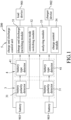
- the battery charge and discharge protection device 200 may be integrated with the load device 901 in an electronic product such as a speaker or a microphone, but the disclosure is not limited to such configurations.
- the battery charge and discharge protection device 200 is installed with two batteries 903 in this embodiment.
- the battery polarity detecting unit 3 includes two battery polarity detectors 31 that respectively correspond to the batteries 903.
- the battery type detecting unit 4 includes two battery type detectors 41 that respectively correspond to the batteries 903. With respect to each of the batteries 903, the corresponding battery polarity detector 31 is coupled to the battery 903, and the corresponding battery type detector 41 is coupled to the corresponding battery polarity detector 31.
- the corresponding battery polarity detector 31 determines that the battery 903 is correctly installed, the corresponding battery polarity detector 31 causes the first detection signal to be at, for example, a logic "0" level, and connects the battery 903 to the corresponding battery type detector 41.
- the first detection signals that are respectively generated by the battery polarity detectors 31 collectively constitute a first detection result.
- the charge and discharge switching module 51 performs the following: (a) when operating in the OFF state 511, preventing transmission of power that is received from the connection mode switching module 52 to the load device 901; and (b) when operating in the ON state 512, permitting transmission of power that is received from the connection mode switching module 52 to the load device 901 and transmission of power that is received from the charger device 902 to the connection mode switching module 52.
- the analyzing module 53 is coupled to the battery polarity detecting unit 3 and the battery type detecting unit 4 to receive the first and second detection results, and is further coupled to the charge and discharge switching module 51 and the connection mode switching module 52. Based on analysis of the first and second detection results, the analyzing module 53 controls switching of the charge and discharge switching module 51 between the OFF state 511 and the ON state 512 and switching of the connection mode switching module 52 between the parallel connection mode 521 and the series connection mode 522.
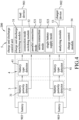
- the analyzing module 53 includes a first logic circuit 531, a second logic circuit 532, a third logic circuit 533 and a fourth logic circuit 534.
- the first logic circuit 531 is coupled to the battery polarity detectors 31 to receive the first detection signals, is further coupled to the charge and discharge switching module 51, and generates, based on the first detection signals, a first logic signal that indicates whether both of the batteries 903 are correctly installed and that is for receipt by the charge and discharge switching module 51.
- the first logic signal causes the charge and discharge switching module 51 to operate in the ON state 512 when indicating that both of the batteries 903 are correctly installed, and causes the charge and discharge switching module 51 to operate in the OFF state 511 when indicating that the batteries 903 are not both correctly installed (i.e., at least one of the batteries 903 is reversely installed).
- the first logic circuit 531 includes an OR gate.
- the OR gate has two input terminals that are respectively coupled to the battery polarity detectors 31 to respectively receive the first detection signals, and an output terminal that is coupled to the charge and discharge switching module 51 and that provides the first logic signal.
- the first logic signal is at a logic "1” level to indicate that the batteries 903 are not both correctly installed.
- the first logic signal is at a logic "0" level to indicate that both of the batteries 903 are correctly installed.
- the second logic circuit 532 is coupled to the battery type detectors 41 to receive the second detection signals, and generates, based on the second detection signals, a second logic signal that indicates whether both of the batteries 903 are non-rechargeable.
- the second logic circuit 532 includes an OR gate.
- the OR gate has two input terminals that are respectively coupled to the battery type detectors 41 to respectively receive the second detection signals, and an output terminal that provides the second logic signal.
- the second logic signal is at a logic "1" level to indicate that the batteries 903 are not both non-rechargeable (i.e., at least one of the batteries 903 is rechargeable).
- both of the second detection signals are at the logic "0" level
- the second logic signal is at a logic "0" level to indicate that both of the batteries 903 are non-rechargeable.
- the third logic circuit 533 is coupled to the battery type detectors 41 to receive the inverted second detection signals, is further coupled to the connection mode switching module 52, and generates, based on the inverted second detection signals, a third logic signal that indicates whether both of the batteries 903 are rechargeable and that is for receipt by the connection mode switching module 52.
- the third logic signal causes the connection mode switching module 52 to operate in the series connection mode 522 when indicating that the batteries 903 are not both rechargeable (i.e., at least one of the batteries 903 is non-rechargeable), and is dismissed as inconsequential when indicating that both of the batteries 903 are rechargeable.
- the third logic circuit 533 includes an OR gate.
- the OR gate has two input terminals that are respectively coupled to the battery type detectors 41 to respectively receive the inverted second detection signals, and an output terminal that is coupled to the connection mode switching module 52 and that provides the third logic signal.
- the third logic signal is at a logic "1” level to indicate that the batteries 903 are not both rechargeable.
- both of the inverting second detection signals are at the logic "0" level
- the third logic signal is at a logic "0" level to indicate that both of the batteries 903 are rechargeable.
- the fourth logic circuit 534 is coupled to the first to third logic circuits 531-533 to receive the first to third logic signals, is further coupled to the connection mode switching module 52, and generates a fourth logic signal based on the first to third logic signals for receipt by the connection mode switching module 52.
- the fourth logic signal causes the connection mode switching module 52 to operate in the parallel connection mode 522 when all of the following conditions are met: the first logic signal indicates that both of the batteries 903 are correctly installed; the second logic signal indicates that the batteries 903 are not both non-rechargeable; and the third logic signal indicates that both of the batteries 903 are rechargeable.
- the fourth logic signal does not matter when otherwise.
- the fourth logic circuit 534 includes a first inverter, a second inverter and an AND gate.
- the first inverter has an input terminal that is coupled to the output terminal of the OR gate of the first logic circuit 531, and an output terminal.
- the second inverter has an input terminal that is coupled to the output terminal of the OR gate of the third logic circuit 533, and an output terminal.
- the AND gate has three input terminals that are respectively coupled to the output terminal of the OR gate of the second logic circuit 532, the output terminal of the first inverter and the output terminal of the second inverter.
- the AND gate further has an output terminal that is coupled to the connection mode switching module 52 and that provides the fourth logic signal.
- the first logic signal is at the logic "0” level
- the second logic signal is at the logic "1” level
- the third logic signal is at the logic "0” level
- the fourth logic signal is at a logic "1” level so as to cause the connection mode switching module 52 to operate in the parallel connection mode 521.
- the first logic signal is at the logic "0" level
- the second logic signal is at the logic "1” level
- the third logic signal is at the logic "1” level so as to cause the connection mode switching module 52 to operate in the series connection mode 522
- the fourth logic signal is at a logic "0" level.
- the charge control module 54 is adapted to be coupled to the charger device 902, is further coupled to the fourth logic circuit 534 to receive the fourth logic signal, controls the charger device 902 to output power to the charge and discharge switching module 51 when the fourth logic signal causes the connection mode switching module 52 to operate in the parallel connection mode 521 (i.e., the fourth logic signal is at the logic "1" level), and controls the charger device 902 to not output power to the charge and discharge switching module 51 when otherwise (i.e., the fourth logic signal is at the logic "0" level).
- the charge control module 54 includes a buffer.
- step 801 the battery polarity detecting unit 3 detects, with respect to each of the batteries 903, whether the battery 903 is correctly installed or reversely installed, so as to generate the first detection result.
- the battery polarity detecting unit 3 connects the battery 903 to the battery type detecting unit 4 when the first detection result indicates that the battery 903 is correctly installed.
- step 802 the battery type detecting unit 4, when being connected to any one of the batteries 903 by the battery polarity detecting unit 3, detects whether the battery 903 is rechargeable or non-rechargeable, so as to generate the second detection result.
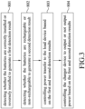
- the analyzing module 53 determines based on the first detection result that at least one of the batteries 903 is reversely installed, the analyzing module 53 controls the charge and discharge switching module 51 to operate in the OFF state 511, and controls, via the charge control module 54, the charger device 902 to not output power, so as to disable power transfer from the batteries 903 to the load device 901 and power transfer from the charger device 902 to the batteries 903. Therefore, both of the batteries 903 are neither supplying power to the load device 901, nor being charged by the charger device 902.
- the analyzing module 53 determines based on the first detection result that both of the batteries 903 are correctly installed and determines based on the second detection result that at least one of the batteries 903 is non-rechargeable, the analyzing module 53 controls the charge and discharge switching module 51 to operate in the ON state 512, controls the connection mode switching module 52 to operate in the series connection mode 522, and controls, via the charge control module 54, the charger device 902 to not output power, so as to connect the batteries 903 in series, enable power transfer from the series connected batteries 903 to the load device 901, and disable power transfer from the charger device 902 to the series connected batteries 903. Therefore, both of the batteries 903 are supplying power to the load device 901, and none of the batteries 903 are being charged by the charger device 902.
- the number of the batteries 903 is not limited to two, and can be increased.
- the number of the battery polarity detectors 31 and the number of the battery type detectors 41 should be increased as well.
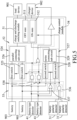
- the first logic circuit 536 is coupled to the battery polarity detectors 31 to receive the first detection signals, is further coupled to the charge and discharge switching module 51, and generates, based on the first detection signals, a first logic signal that indicates whether both of the batteries 903 are correctly installed and that is for receipt by the charge and discharge switching module 51.
- the first logic signal causes the charge and discharge switching module 51 to operate in the ON state 512 when indicating that both of the batteries 903 are correctly installed, and causes the charge and discharge switching module 51 to operate in the OFF state 511 when indicating that the batteries 903 are not both correctly installed (i.e., at least one of the batteries 903 is reversely installed).
- the first logic circuit 536 includes an AND gate.
- the AND gate has two input terminals that are respectively coupled to the battery polarity detectors 31 to respectively receive the first detection signals, and an output terminal that is coupled to the charge and discharge switching module 51 and that provides the first logic signal.
- the first logic signal is at a logic "1” level to indicate that both of the batteries 903 are correctly installed.
- the first logic signal is at a logic "0" level to indicate that the batteries 903 are not both correctly installed.
- the third logic signals that are respectively generated by the third logic circuits 538 respectively cause the first switches 525 to conduct (i.e., collectively causing the connection mode switching module 52 to operate in the parallel connection mode 521).
- the third logic signals will cause only one of the first switches 525 to conduct (i.e., collectively causing the connection mode switching module 52 to operate in the single battery supply mode 523). Otherwise, the third logic signals respectively cause the first switches 525 to not conduct.
- the first switches 525 When both of the first switches 525 conduct, the first switches 525 respectively connect the batteries 903 to the parallel connecting sub-circuit 526, and the parallel connecting sub-circuit 526 connects the batteries 903 in parallel, permits transmission of power that is received from the parallel connected batteries 903 to the charge and discharge switching module 51, and permits transmission of power that is received from the charge and discharge switching module 51 to the parallel connected batteries 903.
- the analyzing module 53 determines based on the first detection result that at least one of the batteries 903 is reversely installed, the analyzing module 53 controls the charge and discharge switching module 51 to operate in the OFF state 511, and controls, via the charge control module 54, the charger device 902 to not output power, so as to disable power transfer from the batteries 903 to the load device 901 and power transfer from the charger device 902 to the batteries 903. Therefore, both of the batteries 903 are neither supplying power to the load device 901, nor being charged by the charger device 902.
- the analyzing module 53 determines based on the first detection result that both of the batteries 903 are correctly installed and determines based on the second detection result that both of the batteries 903 are rechargeable, the analyzing module 53 controls the charge and discharge switching module 51 to operate in the ON state 512, controls the connection mode switching module 52 to operate in the parallel connection mode 521, and controls, via the charge control module 54, the charger device 902 to output power, so as to connect the batteries 903 in parallel, and enable power transfer from the parallel connected batteries 903 to the load device 901 and power transfer from the charger device 902 to the parallel connected batteries 903. Therefore, both of the batteries 903 are supplying power to the load device 901, and are being charged by the charger device 902.
- the battery charge and discharge protection device 200 of this embodiment performs one of the following actions based on the types of the batteries 903: when both of the batteries 903 are rechargeable, connecting the batteries 903 in parallel, and permitting the parallel connected batteries 903 to supply power to the load device 903; when only one of the batteries 903 is rechargeable, permitting the rechargeable battery 903 to supply power to the load device 903; and when both of the batteries 903 are non-rechargeable, connecting the batteries 903 in series, and permitting the series connected batteries 903 to supply power to the load device 903, thereby optimizing power transfer from the batteries 903 to the load device 903.
Landscapes
- Engineering & Computer Science (AREA)
- Power Engineering (AREA)
- Charge And Discharge Circuits For Batteries Or The Like (AREA)
- Secondary Cells (AREA)
Claims (7)
- Batterielade- und -entladeschutzvorrichtung (200), die geeignet ist, mit einer Lastvorrichtung (901) und einer Ladevorrichtung (902) gekoppelt zu werden, und in die zwei Batterien (903) eingesetzt werden können, wobei die Batterielade- und -entladeschutzvorrichtung (200) dadurch gekennzeichnet ist, dass sie umfasst:eine Batteriepolaritätserkennungseinheit (3), die geeignet ist, mit den Batterien (903) gekoppelt zu werden, und konfiguriert ist, um in Bezug auf jede der Batterien (903) zu erkennen, ob die Batterie (903) korrekt oder verkehrt herum eingesetzt ist, um ein erstes Erkennungsergebnis zu erzeugen;eine Batterietyperkennungseinheit (4), die angeordnet und konfiguriert ist, um in Bezug auf jede der Batterien (903) zu erkennen, ob die Batterie (903) wiederaufladbar oder nicht wiederaufladbar ist, um ein zweites Erkennungsergebnis zu erzeugen; undeine Lade- und Entladesteuereinheit (5), die mit der Batteriepolaritätserkennungseinheit (3) und der Batterietyperkennungseinheit (4), die geeignet ist, das erste und zweite Erkennungsergebnis zu empfangen, gekoppelt ist und geeignet ist, ferner mit der Lastvorrichtung (901), der Ladevorrichtung (902) und den Batterien (903) gekoppelt zu werden;wobei, wenn die Lade- und Entladesteuereinheit (5) basierend auf dem ersten Erkennungsergebnis bestimmt, dass mindestens eine der Batterien (903) verkehrt herum eingesetzt ist, die Lade- und Entladesteuereinheit (5) die Energieübertragung von den Batterien (903) an die Lastvorrichtung (901) deaktiviert und die Energieübertragung von der Ladevorrichtung (902) an die Batterien (903) deaktiviert;wobei, wenn die Lade- und Entladesteuereinheit (5) basierend auf dem ersten Erkennungsergebnis bestimmt, dass beide Batterien (903) korrekt eingesetzt sind, und basierend auf dem zweiten Erkennungsergebnis bestimmt, dass beide Batterien (903) wiederaufladbar sind, die Lade- und Entladesteuereinheit (5) die Batterien (903) parallel schaltet, eine Energieübertragung von den Batterien (903), die parallel geschaltet wurden, an die Lastvorrichtung (901) aktiviert und eine Energieübertragung von der Ladevorrichtung (902) an die Batterien (903), die parallel geschaltet wurden, aktiviert;wobei, wenn die Lade- und Entladesteuereinheit (5) basierend auf dem ersten Erkennungsergebnis bestimmt, dass beide Batterien (903) korrekt eingesetzt sind, und basierend auf dem zweiten Erkennungsergebnis bestimmt, dass nur eine der Batterien (903) wiederaufladbar ist, die Lade- und Entladesteuereinheit (5) eine Energieübertragung von der Batterie (903), die als wiederaufladbar bestimmt wird, an die Lastvorrichtung (901) aktiviert und eine Energieübertragung von der Ladevorrichtung (902) an die Batterie (903), die als wiederaufladbar bestimmt wird, aktiviert.
- Batterielade- und -entladeschutzvorrichtung (200) nach Anspruch 1, dadurch gekennzeichnet, dass die Lade- und Entladesteuereinheit (5) einschließt:ein Lade- und Entladeumschaltmodul (51), das geeignet ist, mit der Lastvorrichtung (901) und der Ladevorrichtung (902) gekoppelt zu werden, und das in einer Vielzahl von Zuständen betreibbar ist, die einen AUS-Zustand (511) und einen EIN-Zustand (512) einschließen;ein Verbindungsmodusumschaltmodul (52), das geeignet ist, mit den Batterien (903) gekoppelt zu werden, ferner mit dem Lade- und Entladeumschaltmodul (51) gekoppelt ist und in einer Vielzahl von Verbindungsmodi betreibbar ist, die einen Parallelverbindungsmodus (521) und einen Einzelbatterieversorgungsmodus (523) einschließen;wobei das Lade- und Entladeumschaltmodul (51), wenn es im AUS-Zustand (511) arbeitet, die Übertragung von Energie, die von dem Verbindungsmodusumschaltmodul (52) empfangen wird, an die Lastvorrichtung (901) verhindert;wobei das Lade- und Entladeumschaltmodul (51), wenn es im EIN-Zustand (512) arbeitet, die Übertragung von Energie, die von dem Verbindungsmodusumschaltmodul (52) empfangen wird, an die Lastvorrichtung (901) und die Übertragung von Energie, die von der Ladevorrichtung (902) empfangen wird, an das Verbindungsmodusumschaltmodul (52) ermöglicht;wobei, wenn das Verbindungsmodusumschaltmodul (52) in dem Parallelverbindungsmodus (521) arbeitet, das Verbindungsmodusumschaltmodul (52) die Batterien (903) parallel schaltet und die Übertragung von Energie, die von den Batterien (903) empfangen wird, die parallel geschaltet wurden, an das Lade- und Entladeumschaltmodul (51) und die Übertragung von Energie, die von dem Lade- und Entladeumschaltmodul (51) empfangen wird, an die Batterien (903), die parallel geschaltet wurden, ermöglicht;wobei, wenn das Verbindungsmodusumschaltmodul (52) in dem Einzelbatterieversorgungsmodus (523) arbeitet, das Verbindungsmodusumschaltmodul (52) die Übertragung von Energie, die von der als wiederaufladbar bestimmten Batterie (903) empfangen wird, an das Lade- und Entladeumschaltmodul (51) und die Übertragung von Energie, die von dem Lade- und Entladeumschaltmodul (51) empfangen wird, an die als wiederaufladbar bestimmte Batterie (903) ermöglicht; undein Analysemodul (53), das mit der Batteriepolaritätserkennungseinheit (3) und der Batterietyperkennungseinheit (4) gekoppelt ist und geeignet ist, das erste und das zweite Erkennungsergebnis zu empfangen, und das ferner mit dem Lade- und Entladeschaltmodul (51) und dem Verbindungsmodusumschaltmodul (52) gekoppelt ist;wobei das Analysemodul (53) basierend auf der Analyse des ersten und des zweiten Erkennungsergebnisses das Umschalten des Lade- und Entladeumschaltmoduls (51) zwischen dem AUS-Zustand (511) und dem EIN-Zustand (512) und das Umschalten des Verbindungsmodusumschaltmoduls (52) zwischen dem Parallelverbindungsmodus (521) und dem Einzelbatterieversorgungsmodus (523) steuert.
- Batterielade- und -entladeschutzvorrichtung (200) nach Anspruch 2, dadurch gekennzeichnet, dass:die Verbindungsmodi ferner einen Reihenverbindungsmodus (522) einschließen;wobei, wenn das Verbindungsmodusumschaltmodul (52) in dem Reihenverbindungsmodus (522) arbeitet, das Verbindungsmodusumschaltmodul (52) die Batterien (903) in Reihe schaltet und die Übertragung von Energie, die von den in Reihe geschalteten Batterien (903) empfangen wird, an das Lade- und Entladeumschaltmodul (51) ermöglicht;wobei das Analysemodul (53), wenn basierend auf dem ersten Erkennungsergebnis bestimmt wird, dass beide Batterien (903) korrekt eingesetzt sind, und wenn basierend auf dem zweiten Erkennungsergebnis bestimmt wird, dass beide Batterien (903) nicht wiederaufladbar sind, das Verbindungsmodusumschaltmodul (52) so steuert, dass es in dem Reihenverbindungsmodus (522) arbeitet;wobei die Lade- und Entladesteuereinheit (5) ferner ein Ladesteuermodul (54) einschließt, das geeignet ist, mit der Ladevorrichtung (902) gekoppelt zu werden, und das ferner mit dem Analysemodul (53) gekoppelt ist;wobei, wenn das Analysemodul (53) das Verbindungsmodusumschaltmodul (52) so steuert, dass es in einem von dem Parallelverbindungsmodus (521) und dem Einzelbatterieversorgungsmodus (523) arbeitet, das Ladesteuermodul (54) die Ladevorrichtung (902) steuert, um Energie an das Lade- und Entladeumschaltmodul (51) auszugeben.
- Batterielade- und -entladeschutzvorrichtung (200) nach Anspruch 3, dadurch gekennzeichnet, dass:das zweite Erkennungsergebnis zwei zweite Erkennungssignale einschließt, die jeweils den Batterien (903) entsprechen und von denen jedes angibt, ob die Batterie (903), die dem zweiten Erkennungssignal entspricht, wiederaufladbar oder nicht wiederaufladbar ist; unddas Analysemodul (53) einschließteine erste Logikschaltung (536), die mit der Batteriepolaritätserkennungseinheit (3) gekoppelt ist, um das erste Erkennungsergebnis zu empfangen, ferner mit dem Lade- und Entladeumschaltmodul (51) gekoppelt ist und basierend auf dem ersten Erkennungsergebnis ein erstes Logiksignal erzeugt, das angibt, ob beide Batterien (903) korrekt eingesetzt sind, und das zum Empfang durch das Lade- und Entladeumschaltmodul (51) vorgesehen ist,wobei das erste Logiksignal, wenn es angibt, dass beide Batterien (903) korrekt eingesetzt sind, das Lade- und Entladeumschaltmodul (51) veranlasst, im EIN-Zustand (512) zu arbeiten,eine zweite Logikschaltung (537), die mit der Batterietyperkennungseinheit (4) gekoppelt ist, um das zweite Erkennungsergebnis zu empfangen, ferner mit dem Verbindungsmodusumschaltmodul (52) gekoppelt ist und basierend auf dem zweiten Erkennungsergebnis ein zweites Logiksignal erzeugt, das angibt, ob beide Batterien (903) nicht wiederaufladbar sind, und das zum Empfang durch das Verbindungsmodusumschaltmodul (52) vorgesehen ist,wobei das zweite Logiksignal, wenn es angibt, dass beide Batterien (903) nicht wiederaufladbar sind, das Verbindungsmodusumschaltmodul (52) veranlasst, in dem Reihenverbindungsmodus (522) zu arbeiten, undzwei dritte Logikschaltungen (538), die jeweils den Batterien (903) entsprechen,wobei in Bezug auf jede der Batterien (903) die dritte Logikschaltung (538), die der Batterie (903) entspricht, die mit der ersten Logikschaltung (536) und der Batterietyperkennungseinheit (4) gekoppelt ist, um das erste Logiksignal und das zweite Erkennungssignal, das der Batterie (903) entspricht, zu empfangen, ferner mit dem Verbindungsmodusumschaltmodul (52) gekoppelt ist und ein drittes Logiksignal zum Empfang durch das Verbindungsmodusumschaltmodul (52) basierend auf dem ersten Logiksignal und dem zweiten Erkennungssignal das der Batterie (903) entspricht, erzeugt,wobei, wenn das erste Logiksignal angibt, dass beide Batterien (903) korrekt eingesetzt sind, und wenn die zweiten Erkennungssignale gemeinsam angeben, dass beide Batterien (903) wiederaufladbar sind, die dritten Logiksignale, die jeweils von den dritten Logikschaltungen (538) erzeugt werden, gemeinsam das Verbindungsmodusumschaltmodul (52) veranlassen, in dem Parallelverbindungsmodus (521) zu arbeiten,wobei, wenn das erste Logiksignal angibt, dass beide Batterien (903) korrekt eingesetzt sind, und wenn die zweiten Erkennungssignale gemeinsam angeben, dass nur eine der Batterien (903) wiederaufladbar ist, die dritten Logiksignale, die jeweils von den dritten Logikschaltungen (538) erzeugt werden, gemeinsam das Verbindungsmodusumschaltmodul (52) veranlassen, in dem Einzelbatterieversorgungsmodus (523) zu arbeiten.
- Batterielade- und -entladeschutzvorrichtung (200) nach Anspruch 4, dadurch gekennzeichnet, dass:das Verbindungsmodusumschaltmodul (52) eine Reihenverbindungsmodusschaltung (527) und eine Parallelverbindungsmodusschaltung (524) einschließt;jede der Reihenverbindungsmodusschaltung (527) und der Parallelverbindungsmodusschaltung (524) geeignet ist, mit den Batterien (903) gekoppelt zu werden, und ferner mit dem Lade- und Entladeumschaltmodul (51) gekoppelt ist;wobei, wenn das Verbindungsmodusumschaltmodul (52) in dem Reihenverbindungsmodus (522) arbeitet, die Reihenverbindungsmodusschaltung (527) die Batterien (903) in Reihe schaltet und die Übertragung von Energie, die von den in Reihe geschalteten Batterien (903) empfangen wird, an das Lade- und Entladeumschaltmodul (51) ermöglicht;die Parallelverbindungsmodusschaltung (524) zwei erste Schalter (525), die geeignet sind, jeweils mit den Batterien (903) gekoppelt zu werden, und eine Parallelverbindungsteilschaltung (526), die mit den ersten Schaltern (525) und dem Lade- und Entladeumschaltmodul (51) gekoppelt ist, einschließt;jeder der ersten Schalter (525) ferner mit der dritten Logikschaltung (538) gekoppelt ist, die der mit dem ersten Schalter (525) gekoppelten Batterie (903) entspricht, um das dritte Logiksignal zu empfangen, und leitet, um die mit dem ersten Schalter (525) gekoppelte Batterie (903) mit der Parallelverbindungsteilschaltung (526) zu verbinden, wenn das dritte Logiksignal angibt, dass beide Batterien (903) korrekt eingesetzt sind und dass die mit dem ersten Schalter (525) gekoppelte Batterie (903) wiederaufladbar ist;wobei, wenn beide ersten Schalter (525) leiten, die Parallelverbindungsteilschaltung (526) die Batterien (903) parallel schaltet und die Übertragung von Energie, die von den Batterien (903) empfangen wird, die parallel geschaltet wurden, an das Lade- und Entladeumschaltmodul (51) und die Übertragung von Energie, die von dem Lade- und Entladeumschaltmodul (51) empfangen wird, an die Batterien (903), die parallel geschaltet wurden, ermöglicht;wobei, wenn nur einer der ersten Schalter (525) leitet, die Parallelverbindungsteilschaltung (526) die Übertragung von Energie, die von der mit der Parallelverbindungsteilschaltung (526) verbundenen Batterie (903) empfangen wird, an das Lade- und Entladeumschaltmodul (51) und die Übertragung von Energie, die von dem Lade- und Entladeumschaltmodul (51) empfangen wird, an die mit der Parallelverbindungsteilschaltung (526) verbundene Batterie (903) ermöglicht.
- Batterielade- und -entladeschutzvorrichtung (200) nach Anspruch 5, dadurch gekennzeichnet, dass:die Reihenverbindungsmodusschaltung (527) zwei zweite Schalter (528), die geeignet sind, jeweils mit den Batterien (903) gekoppelt zu werden, und eine Reihenverbindungsteilschaltung (529), die mit den zweiten Schaltern (528) und dem Lade- und Entladeumschaltmodul (51) gekoppelt ist, einschließt;jeder der zweiten Schalter (528) ferner mit der zweiten Logikschaltung (537) gekoppelt ist, um das zweite Logiksignal zu empfangen, und leitet, um die mit dem zweiten Schalter (528) gekoppelte Batterie (903) mit der Reihenverbindungsteilschaltung (529) zu verbinden, wenn das zweite Logiksignal angibt, dass beide Batterien (903) nicht wiederaufladbar sind;wobei, wenn beide der zweiten Schalter (528) leiten, die Reihenverbindungsteilschaltung (529) die Batterien (903) in Reihe schaltet und die Übertragung von Energie, die von den in Reihe geschalteten Batterien (903) empfangen wird, an das Lade- und Entladeumschaltmodul (51) ermöglicht.
- Batterielade- und -entladeschutzvorrichtung (200) nach einem der Ansprüche 4 bis 6, dadurch gekennzeichnet, dass das Ladesteuermodul (54) mit den dritten Logikschaltungen (538) gekoppelt ist, um die dritten Logiksignale zu empfangen, und die Ladevorrichtung (902) steuert, um Energie an das Lade- und Entladeumschaltmodul (51) auszugeben, wenn die dritten Logiksignale gemeinsam das Verbindungsmodusumschaltmodul (52) veranlassen, in einem von dem Parallelverbindungsmodus (521) und dem Einzelbatterieversorgungsmodus (523) zu arbeiten.
Priority Applications (1)
| Application Number | Priority Date | Filing Date | Title |
|---|---|---|---|
| EP22213958.6A EP4254716B1 (de) | 2022-03-22 | 2022-03-22 | Vorrichtung und verfahren zum schutz vor ladung und entladung einer batterie |
Applications Claiming Priority (2)
| Application Number | Priority Date | Filing Date | Title |
|---|---|---|---|
| EP22213958.6A EP4254716B1 (de) | 2022-03-22 | 2022-03-22 | Vorrichtung und verfahren zum schutz vor ladung und entladung einer batterie |
| EP22163554.3A EP4250517B1 (de) | 2022-03-22 | 2022-03-22 | Batterielade- und -entladeschutzvorrichtung und verfahren |
Related Parent Applications (2)
| Application Number | Title | Priority Date | Filing Date |
|---|---|---|---|
| EP22163554.3A Division EP4250517B1 (de) | 2022-03-22 | 2022-03-22 | Batterielade- und -entladeschutzvorrichtung und verfahren |
| EP22163554.3A Division-Into EP4250517B1 (de) | 2022-03-22 | 2022-03-22 | Batterielade- und -entladeschutzvorrichtung und verfahren |
Publications (3)
| Publication Number | Publication Date |
|---|---|
| EP4254716A1 EP4254716A1 (de) | 2023-10-04 |
| EP4254716C0 EP4254716C0 (de) | 2024-07-03 |
| EP4254716B1 true EP4254716B1 (de) | 2024-07-03 |
Family
ID=80930075
Family Applications (2)
| Application Number | Title | Priority Date | Filing Date |
|---|---|---|---|
| EP22213958.6A Active EP4254716B1 (de) | 2022-03-22 | 2022-03-22 | Vorrichtung und verfahren zum schutz vor ladung und entladung einer batterie |
| EP22163554.3A Active EP4250517B1 (de) | 2022-03-22 | 2022-03-22 | Batterielade- und -entladeschutzvorrichtung und verfahren |
Family Applications After (1)
| Application Number | Title | Priority Date | Filing Date |
|---|---|---|---|
| EP22163554.3A Active EP4250517B1 (de) | 2022-03-22 | 2022-03-22 | Batterielade- und -entladeschutzvorrichtung und verfahren |
Country Status (1)
| Country | Link |
|---|---|
| EP (2) | EP4254716B1 (de) |
Families Citing this family (1)
| Publication number | Priority date | Publication date | Assignee | Title |
|---|---|---|---|---|
| DE102024201214A1 (de) * | 2024-02-09 | 2025-08-14 | Shimano Inc. | Komponente für ein menschlich angetriebenes Fahrzeug |
Family Cites Families (3)
| Publication number | Priority date | Publication date | Assignee | Title |
|---|---|---|---|---|
| US10784680B2 (en) * | 2015-01-23 | 2020-09-22 | Elevate Technologies Corporation | Adaptable recharging and lighting station and methods of using the same |
| US12040638B2 (en) * | 2018-10-03 | 2024-07-16 | Switching Battery Inc. | Energy storage system and method to improve battery performance by battery connection method |
| US11245272B2 (en) * | 2020-05-28 | 2022-02-08 | Fuyuan Electronic Co., Ltd | Output protector for charger |
-
2022
- 2022-03-22 EP EP22213958.6A patent/EP4254716B1/de active Active
- 2022-03-22 EP EP22163554.3A patent/EP4250517B1/de active Active
Also Published As
| Publication number | Publication date |
|---|---|
| EP4254716C0 (de) | 2024-07-03 |
| EP4254716A1 (de) | 2023-10-04 |
| EP4250517B1 (de) | 2025-09-10 |
| EP4250517C0 (de) | 2025-09-10 |
| EP4250517A1 (de) | 2023-09-27 |
Similar Documents
| Publication | Publication Date | Title |
|---|---|---|
| US6624614B2 (en) | Charge and discharge controller | |
| US9035618B2 (en) | Battery pack and method of controlling the same | |
| US6639387B2 (en) | Battery pack and inspection device therefor | |
| EP3327892B1 (de) | Lade- und entladesteuerschaltung und batteriepack | |
| US5789900A (en) | Device for protecting a secondary battery from overcharge and overdischarge | |
| KR100281534B1 (ko) | 휴대용 컴퓨터의 배터리팩 선택 회로 | |
| KR101182890B1 (ko) | 배터리 팩 충전 제어 시스템 | |
| US8698459B2 (en) | Battery pack and method of controlling the same | |
| US20100239896A1 (en) | Protection Device For Secondary Batteries, And Battery Pack And Electronic Equipment Employing Same | |
| US20120256598A1 (en) | Battery Pack Detection Circuit | |
| KR101201139B1 (ko) | 배터리 팩의 보호 회로 장치 | |
| US12170452B2 (en) | Charging system and charger for reducing inrush current | |
| EP3771057B1 (de) | Zellenschutzschaltung und elektronische vorrichtung | |
| JP2004120849A (ja) | 外部保護回路を備えた二次電池ユニット | |
| EP3772153B1 (de) | Batterieschutzsystem | |
| EP4254716B1 (de) | Vorrichtung und verfahren zum schutz vor ladung und entladung einer batterie | |
| KR102117315B1 (ko) | 배터리 장치 | |
| KR20160094225A (ko) | 배터리 팩의 과충전 보호 장치 및 과충전 보호 시스템 | |
| KR102332335B1 (ko) | 배터리 팩 | |
| EP3043441B1 (de) | Batterieverwaltungseinheit zur verhinderung eines fehlerhaften steueralgorithmus bei kommunikationsfehlers | |
| US12176741B2 (en) | Battery charge and discharge protection device and method | |
| US20200044462A1 (en) | Charge system, battery pack, and protection apparatus | |
| KR101213479B1 (ko) | 배터리 팩, 및 배터리 팩을 포함한 충전 시스템 및 이의 제어 방법 | |
| CN209881442U (zh) | 电池包 | |
| KR102812086B1 (ko) | 배터리 충방전 보호 장치와 방법 |
Legal Events
| Date | Code | Title | Description |
|---|---|---|---|
| PUAI | Public reference made under article 153(3) epc to a published international application that has entered the european phase |
Free format text: ORIGINAL CODE: 0009012 |
|
| STAA | Information on the status of an ep patent application or granted ep patent |
Free format text: STATUS: REQUEST FOR EXAMINATION WAS MADE |
|
| 17P | Request for examination filed |
Effective date: 20230704 |
|
| AC | Divisional application: reference to earlier application |
Ref document number: 4250517 Country of ref document: EP Kind code of ref document: P |
|
| AK | Designated contracting states |
Kind code of ref document: A1 Designated state(s): AL AT BE BG CH CY CZ DE DK EE ES FI FR GB GR HR HU IE IS IT LI LT LU LV MC MK MT NL NO PL PT RO RS SE SI SK SM TR |
|
| GRAP | Despatch of communication of intention to grant a patent |
Free format text: ORIGINAL CODE: EPIDOSNIGR1 |
|
| STAA | Information on the status of an ep patent application or granted ep patent |
Free format text: STATUS: GRANT OF PATENT IS INTENDED |
|
| INTG | Intention to grant announced |
Effective date: 20240402 |
|
| GRAS | Grant fee paid |
Free format text: ORIGINAL CODE: EPIDOSNIGR3 |
|
| GRAA | (expected) grant |
Free format text: ORIGINAL CODE: 0009210 |
|
| STAA | Information on the status of an ep patent application or granted ep patent |
Free format text: STATUS: THE PATENT HAS BEEN GRANTED |
|
| AC | Divisional application: reference to earlier application |
Ref document number: 4250517 Country of ref document: EP Kind code of ref document: P |
|
| AK | Designated contracting states |
Kind code of ref document: B1 Designated state(s): AL AT BE BG CH CY CZ DE DK EE ES FI FR GB GR HR HU IE IS IT LI LT LU LV MC MK MT NL NO PL PT RO RS SE SI SK SM TR |
|
| REG | Reference to a national code |
Ref country code: CH Ref legal event code: EP |
|
| REG | Reference to a national code |
Ref country code: DE Ref legal event code: R096 Ref document number: 602022004339 Country of ref document: DE |
|
| U01 | Request for unitary effect filed |
Effective date: 20240712 |
|
| U07 | Unitary effect registered |
Designated state(s): AT BE BG DE DK EE FI FR IT LT LU LV MT NL PT SE SI Effective date: 20240725 |
|
| PG25 | Lapsed in a contracting state [announced via postgrant information from national office to epo] |
Ref country code: NO Free format text: LAPSE BECAUSE OF FAILURE TO SUBMIT A TRANSLATION OF THE DESCRIPTION OR TO PAY THE FEE WITHIN THE PRESCRIBED TIME-LIMIT Effective date: 20241003 |
|
| PG25 | Lapsed in a contracting state [announced via postgrant information from national office to epo] |
Ref country code: PL Free format text: LAPSE BECAUSE OF FAILURE TO SUBMIT A TRANSLATION OF THE DESCRIPTION OR TO PAY THE FEE WITHIN THE PRESCRIBED TIME-LIMIT Effective date: 20240703 Ref country code: GR Free format text: LAPSE BECAUSE OF FAILURE TO SUBMIT A TRANSLATION OF THE DESCRIPTION OR TO PAY THE FEE WITHIN THE PRESCRIBED TIME-LIMIT Effective date: 20241004 |
|
| PG25 | Lapsed in a contracting state [announced via postgrant information from national office to epo] |
Ref country code: IS Free format text: LAPSE BECAUSE OF FAILURE TO SUBMIT A TRANSLATION OF THE DESCRIPTION OR TO PAY THE FEE WITHIN THE PRESCRIBED TIME-LIMIT Effective date: 20241103 |
|
| PG25 | Lapsed in a contracting state [announced via postgrant information from national office to epo] |
Ref country code: CZ Free format text: LAPSE BECAUSE OF FAILURE TO SUBMIT A TRANSLATION OF THE DESCRIPTION OR TO PAY THE FEE WITHIN THE PRESCRIBED TIME-LIMIT Effective date: 20240703 Ref country code: HR Free format text: LAPSE BECAUSE OF FAILURE TO SUBMIT A TRANSLATION OF THE DESCRIPTION OR TO PAY THE FEE WITHIN THE PRESCRIBED TIME-LIMIT Effective date: 20240703 |
|
| PG25 | Lapsed in a contracting state [announced via postgrant information from national office to epo] |
Ref country code: RS Free format text: LAPSE BECAUSE OF FAILURE TO SUBMIT A TRANSLATION OF THE DESCRIPTION OR TO PAY THE FEE WITHIN THE PRESCRIBED TIME-LIMIT Effective date: 20241003 Ref country code: ES Free format text: LAPSE BECAUSE OF FAILURE TO SUBMIT A TRANSLATION OF THE DESCRIPTION OR TO PAY THE FEE WITHIN THE PRESCRIBED TIME-LIMIT Effective date: 20240703 |
|
| PG25 | Lapsed in a contracting state [announced via postgrant information from national office to epo] |
Ref country code: RS Free format text: LAPSE BECAUSE OF FAILURE TO SUBMIT A TRANSLATION OF THE DESCRIPTION OR TO PAY THE FEE WITHIN THE PRESCRIBED TIME-LIMIT Effective date: 20241003 Ref country code: PL Free format text: LAPSE BECAUSE OF FAILURE TO SUBMIT A TRANSLATION OF THE DESCRIPTION OR TO PAY THE FEE WITHIN THE PRESCRIBED TIME-LIMIT Effective date: 20240703 Ref country code: NO Free format text: LAPSE BECAUSE OF FAILURE TO SUBMIT A TRANSLATION OF THE DESCRIPTION OR TO PAY THE FEE WITHIN THE PRESCRIBED TIME-LIMIT Effective date: 20241003 Ref country code: IS Free format text: LAPSE BECAUSE OF FAILURE TO SUBMIT A TRANSLATION OF THE DESCRIPTION OR TO PAY THE FEE WITHIN THE PRESCRIBED TIME-LIMIT Effective date: 20241103 Ref country code: HR Free format text: LAPSE BECAUSE OF FAILURE TO SUBMIT A TRANSLATION OF THE DESCRIPTION OR TO PAY THE FEE WITHIN THE PRESCRIBED TIME-LIMIT Effective date: 20240703 Ref country code: GR Free format text: LAPSE BECAUSE OF FAILURE TO SUBMIT A TRANSLATION OF THE DESCRIPTION OR TO PAY THE FEE WITHIN THE PRESCRIBED TIME-LIMIT Effective date: 20241004 Ref country code: ES Free format text: LAPSE BECAUSE OF FAILURE TO SUBMIT A TRANSLATION OF THE DESCRIPTION OR TO PAY THE FEE WITHIN THE PRESCRIBED TIME-LIMIT Effective date: 20240703 Ref country code: CZ Free format text: LAPSE BECAUSE OF FAILURE TO SUBMIT A TRANSLATION OF THE DESCRIPTION OR TO PAY THE FEE WITHIN THE PRESCRIBED TIME-LIMIT Effective date: 20240703 |
|
| U20 | Renewal fee for the european patent with unitary effect paid |
Year of fee payment: 4 Effective date: 20250113 |
|
| PG25 | Lapsed in a contracting state [announced via postgrant information from national office to epo] |
Ref country code: SM Free format text: LAPSE BECAUSE OF FAILURE TO SUBMIT A TRANSLATION OF THE DESCRIPTION OR TO PAY THE FEE WITHIN THE PRESCRIBED TIME-LIMIT Effective date: 20240703 |
|
| PG25 | Lapsed in a contracting state [announced via postgrant information from national office to epo] |
Ref country code: SK Free format text: LAPSE BECAUSE OF FAILURE TO SUBMIT A TRANSLATION OF THE DESCRIPTION OR TO PAY THE FEE WITHIN THE PRESCRIBED TIME-LIMIT Effective date: 20240703 |
|
| PLBE | No opposition filed within time limit |
Free format text: ORIGINAL CODE: 0009261 |
|
| STAA | Information on the status of an ep patent application or granted ep patent |
Free format text: STATUS: NO OPPOSITION FILED WITHIN TIME LIMIT |
|
| 26N | No opposition filed |
Effective date: 20250404 |
|
| PG25 | Lapsed in a contracting state [announced via postgrant information from national office to epo] |
Ref country code: MC Free format text: LAPSE BECAUSE OF FAILURE TO SUBMIT A TRANSLATION OF THE DESCRIPTION OR TO PAY THE FEE WITHIN THE PRESCRIBED TIME-LIMIT Effective date: 20240703 |
|
| REG | Reference to a national code |
Ref country code: CH Ref legal event code: H13 Free format text: ST27 STATUS EVENT CODE: U-0-0-H10-H13 (AS PROVIDED BY THE NATIONAL OFFICE) Effective date: 20251024 |
|
| PG25 | Lapsed in a contracting state [announced via postgrant information from national office to epo] |
Ref country code: CH Free format text: LAPSE BECAUSE OF NON-PAYMENT OF DUE FEES Effective date: 20250331 |
|
| PG25 | Lapsed in a contracting state [announced via postgrant information from national office to epo] |
Ref country code: IE Free format text: LAPSE BECAUSE OF NON-PAYMENT OF DUE FEES Effective date: 20250322 |
|
| U20 | Renewal fee for the european patent with unitary effect paid |
Year of fee payment: 5 Effective date: 20260113 |
|
| PG25 | Lapsed in a contracting state [announced via postgrant information from national office to epo] |
Ref country code: RO Free format text: LAPSE BECAUSE OF FAILURE TO SUBMIT A TRANSLATION OF THE DESCRIPTION OR TO PAY THE FEE WITHIN THE PRESCRIBED TIME-LIMIT Effective date: 20240703 |