EP4254716B1 - Battery charge and discharge protection device and method - Google Patents
Battery charge and discharge protection device and method Download PDFInfo
- Publication number
- EP4254716B1 EP4254716B1 EP22213958.6A EP22213958A EP4254716B1 EP 4254716 B1 EP4254716 B1 EP 4254716B1 EP 22213958 A EP22213958 A EP 22213958A EP 4254716 B1 EP4254716 B1 EP 4254716B1
- Authority
- EP
- European Patent Office
- Prior art keywords
- batteries
- charge
- switching module
- battery
- connection mode
- Prior art date
- Legal status (The legal status is an assumption and is not a legal conclusion. Google has not performed a legal analysis and makes no representation as to the accuracy of the status listed.)
- Active
Links
Images

Classifications
-
- H—ELECTRICITY
- H02—GENERATION; CONVERSION OR DISTRIBUTION OF ELECTRIC POWER
- H02J—ELECTRIC POWER NETWORKS; CIRCUIT ARRANGEMENTS OR SYSTEMS FOR SUPPLYING OR DISTRIBUTING ELECTRIC POWER; SYSTEMS FOR STORING ELECTRIC ENERGY
- H02J7/00—Circuit arrangements for charging or discharging batteries or for supplying loads from batteries
- H02J7/60—Circuit arrangements for charging or discharging batteries or for supplying loads from batteries including safety or protection arrangements
- H02J7/68—Circuit arrangements for charging or discharging batteries or for supplying loads from batteries including safety or protection arrangements using circuits for correcting or protecting against reverse-polarity
-
- H—ELECTRICITY
- H02—GENERATION; CONVERSION OR DISTRIBUTION OF ELECTRIC POWER
- H02J—ELECTRIC POWER NETWORKS; CIRCUIT ARRANGEMENTS OR SYSTEMS FOR SUPPLYING OR DISTRIBUTING ELECTRIC POWER; SYSTEMS FOR STORING ELECTRIC ENERGY
- H02J7/00—Circuit arrangements for charging or discharging batteries or for supplying loads from batteries
- H02J7/40—Circuit arrangements for charging or discharging batteries or for supplying loads from batteries characterised by the exchange of charge or discharge related data
- H02J7/47—Arrangements for checking compatibility or authentication between one component, e.g. a battery or a battery charger, and another component, e.g. a power source
-
- H—ELECTRICITY
- H02—GENERATION; CONVERSION OR DISTRIBUTION OF ELECTRIC POWER
- H02J—ELECTRIC POWER NETWORKS; CIRCUIT ARRANGEMENTS OR SYSTEMS FOR SUPPLYING OR DISTRIBUTING ELECTRIC POWER; SYSTEMS FOR STORING ELECTRIC ENERGY
- H02J7/00—Circuit arrangements for charging or discharging batteries or for supplying loads from batteries
- H02J7/50—Circuit arrangements for charging or discharging batteries or for supplying loads from batteries acting upon multiple batteries simultaneously or sequentially
- H02J7/575—Parallel/serial switching of connection of batteries to charge or load circuit
-
- H—ELECTRICITY
- H02—GENERATION; CONVERSION OR DISTRIBUTION OF ELECTRIC POWER
- H02J—ELECTRIC POWER NETWORKS; CIRCUIT ARRANGEMENTS OR SYSTEMS FOR SUPPLYING OR DISTRIBUTING ELECTRIC POWER; SYSTEMS FOR STORING ELECTRIC ENERGY
- H02J7/00—Circuit arrangements for charging or discharging batteries or for supplying loads from batteries
- H02J7/60—Circuit arrangements for charging or discharging batteries or for supplying loads from batteries including safety or protection arrangements
- H02J7/663—Circuit arrangements for charging or discharging batteries or for supplying loads from batteries including safety or protection arrangements using battery or load disconnect circuits
Definitions
- the disclosure relates to battery charge and discharge techniques, and more particularly to a battery charge and discharge protection device.
- Prior art document US 2021/218251 A1 discloses circuitry to connect a plurality of batteries and adapted to couple the batteries in series or parallel to a load or charger.
- Prior art document US 2016/219664 A1 discloses means to detect if the installed batteries are rechargeable or non-rechargeable batteries.
- the charge and discharge control unit is coupled to the battery polarity detecting unit and the battery type detecting unit to receive the first and second detection results, and is adapted to be further coupled to the load device, the charger device and the batteries.
- the charge and discharge control unit determines based on the first detection result that at least one of the batteries is reversely installed, the charge and discharge control unit disables power transfer from the batteries to the load device, and disables power transfer from the charger device to the batteries.
- the charge and discharge control unit determines based on the first detection result that both of the batteries are correctly installed and determines based on the second detection result that both of the batteries are rechargeable, the charge and discharge control unit connects the batteries in parallel, enables power transfer from the batteries that have been connected in parallel to the load device, and enables power transfer from the charger device to the batteries that have been connected in parallel.
- the charge and discharge control unit determines based on the first detection result that both of the batteries are correctly installed and determines based on the second detection result that only one of the batteries is rechargeable
- the charge and discharge control unit enables power transfer from the battery that is determined to be rechargeable to the load device, and enables power transfer from the charger device to the battery that is determined to be rechargeable.
- the battery charge and discharge protection device 200 may be integrated with the load device 901 in an electronic product such as a speaker or a microphone, but the disclosure is not limited to such configurations.
- the battery charge and discharge protection device 200 is installed with two batteries 903 in this embodiment.
- the battery polarity detecting unit 3 includes two battery polarity detectors 31 that respectively correspond to the batteries 903.
- the battery type detecting unit 4 includes two battery type detectors 41 that respectively correspond to the batteries 903. With respect to each of the batteries 903, the corresponding battery polarity detector 31 is coupled to the battery 903, and the corresponding battery type detector 41 is coupled to the corresponding battery polarity detector 31.
- the corresponding battery polarity detector 31 determines that the battery 903 is correctly installed, the corresponding battery polarity detector 31 causes the first detection signal to be at, for example, a logic "0" level, and connects the battery 903 to the corresponding battery type detector 41.
- the first detection signals that are respectively generated by the battery polarity detectors 31 collectively constitute a first detection result.
- the charge and discharge switching module 51 performs the following: (a) when operating in the OFF state 511, preventing transmission of power that is received from the connection mode switching module 52 to the load device 901; and (b) when operating in the ON state 512, permitting transmission of power that is received from the connection mode switching module 52 to the load device 901 and transmission of power that is received from the charger device 902 to the connection mode switching module 52.
- the analyzing module 53 is coupled to the battery polarity detecting unit 3 and the battery type detecting unit 4 to receive the first and second detection results, and is further coupled to the charge and discharge switching module 51 and the connection mode switching module 52. Based on analysis of the first and second detection results, the analyzing module 53 controls switching of the charge and discharge switching module 51 between the OFF state 511 and the ON state 512 and switching of the connection mode switching module 52 between the parallel connection mode 521 and the series connection mode 522.
- the analyzing module 53 includes a first logic circuit 531, a second logic circuit 532, a third logic circuit 533 and a fourth logic circuit 534.
- the first logic circuit 531 is coupled to the battery polarity detectors 31 to receive the first detection signals, is further coupled to the charge and discharge switching module 51, and generates, based on the first detection signals, a first logic signal that indicates whether both of the batteries 903 are correctly installed and that is for receipt by the charge and discharge switching module 51.
- the first logic signal causes the charge and discharge switching module 51 to operate in the ON state 512 when indicating that both of the batteries 903 are correctly installed, and causes the charge and discharge switching module 51 to operate in the OFF state 511 when indicating that the batteries 903 are not both correctly installed (i.e., at least one of the batteries 903 is reversely installed).
- the first logic circuit 531 includes an OR gate.
- the OR gate has two input terminals that are respectively coupled to the battery polarity detectors 31 to respectively receive the first detection signals, and an output terminal that is coupled to the charge and discharge switching module 51 and that provides the first logic signal.
- the first logic signal is at a logic "1” level to indicate that the batteries 903 are not both correctly installed.
- the first logic signal is at a logic "0" level to indicate that both of the batteries 903 are correctly installed.
- the second logic circuit 532 is coupled to the battery type detectors 41 to receive the second detection signals, and generates, based on the second detection signals, a second logic signal that indicates whether both of the batteries 903 are non-rechargeable.
- the second logic circuit 532 includes an OR gate.
- the OR gate has two input terminals that are respectively coupled to the battery type detectors 41 to respectively receive the second detection signals, and an output terminal that provides the second logic signal.
- the second logic signal is at a logic "1" level to indicate that the batteries 903 are not both non-rechargeable (i.e., at least one of the batteries 903 is rechargeable).
- both of the second detection signals are at the logic "0" level
- the second logic signal is at a logic "0" level to indicate that both of the batteries 903 are non-rechargeable.
- the third logic circuit 533 is coupled to the battery type detectors 41 to receive the inverted second detection signals, is further coupled to the connection mode switching module 52, and generates, based on the inverted second detection signals, a third logic signal that indicates whether both of the batteries 903 are rechargeable and that is for receipt by the connection mode switching module 52.
- the third logic signal causes the connection mode switching module 52 to operate in the series connection mode 522 when indicating that the batteries 903 are not both rechargeable (i.e., at least one of the batteries 903 is non-rechargeable), and is dismissed as inconsequential when indicating that both of the batteries 903 are rechargeable.
- the third logic circuit 533 includes an OR gate.
- the OR gate has two input terminals that are respectively coupled to the battery type detectors 41 to respectively receive the inverted second detection signals, and an output terminal that is coupled to the connection mode switching module 52 and that provides the third logic signal.
- the third logic signal is at a logic "1” level to indicate that the batteries 903 are not both rechargeable.
- both of the inverting second detection signals are at the logic "0" level
- the third logic signal is at a logic "0" level to indicate that both of the batteries 903 are rechargeable.
- the fourth logic circuit 534 is coupled to the first to third logic circuits 531-533 to receive the first to third logic signals, is further coupled to the connection mode switching module 52, and generates a fourth logic signal based on the first to third logic signals for receipt by the connection mode switching module 52.
- the fourth logic signal causes the connection mode switching module 52 to operate in the parallel connection mode 522 when all of the following conditions are met: the first logic signal indicates that both of the batteries 903 are correctly installed; the second logic signal indicates that the batteries 903 are not both non-rechargeable; and the third logic signal indicates that both of the batteries 903 are rechargeable.
- the fourth logic signal does not matter when otherwise.
- the fourth logic circuit 534 includes a first inverter, a second inverter and an AND gate.
- the first inverter has an input terminal that is coupled to the output terminal of the OR gate of the first logic circuit 531, and an output terminal.
- the second inverter has an input terminal that is coupled to the output terminal of the OR gate of the third logic circuit 533, and an output terminal.
- the AND gate has three input terminals that are respectively coupled to the output terminal of the OR gate of the second logic circuit 532, the output terminal of the first inverter and the output terminal of the second inverter.
- the AND gate further has an output terminal that is coupled to the connection mode switching module 52 and that provides the fourth logic signal.
- the first logic signal is at the logic "0” level
- the second logic signal is at the logic "1” level
- the third logic signal is at the logic "0” level
- the fourth logic signal is at a logic "1” level so as to cause the connection mode switching module 52 to operate in the parallel connection mode 521.
- the first logic signal is at the logic "0" level
- the second logic signal is at the logic "1” level
- the third logic signal is at the logic "1” level so as to cause the connection mode switching module 52 to operate in the series connection mode 522
- the fourth logic signal is at a logic "0" level.
- the charge control module 54 is adapted to be coupled to the charger device 902, is further coupled to the fourth logic circuit 534 to receive the fourth logic signal, controls the charger device 902 to output power to the charge and discharge switching module 51 when the fourth logic signal causes the connection mode switching module 52 to operate in the parallel connection mode 521 (i.e., the fourth logic signal is at the logic "1" level), and controls the charger device 902 to not output power to the charge and discharge switching module 51 when otherwise (i.e., the fourth logic signal is at the logic "0" level).
- the charge control module 54 includes a buffer.
- step 801 the battery polarity detecting unit 3 detects, with respect to each of the batteries 903, whether the battery 903 is correctly installed or reversely installed, so as to generate the first detection result.
- the battery polarity detecting unit 3 connects the battery 903 to the battery type detecting unit 4 when the first detection result indicates that the battery 903 is correctly installed.
- step 802 the battery type detecting unit 4, when being connected to any one of the batteries 903 by the battery polarity detecting unit 3, detects whether the battery 903 is rechargeable or non-rechargeable, so as to generate the second detection result.
- the analyzing module 53 determines based on the first detection result that at least one of the batteries 903 is reversely installed, the analyzing module 53 controls the charge and discharge switching module 51 to operate in the OFF state 511, and controls, via the charge control module 54, the charger device 902 to not output power, so as to disable power transfer from the batteries 903 to the load device 901 and power transfer from the charger device 902 to the batteries 903. Therefore, both of the batteries 903 are neither supplying power to the load device 901, nor being charged by the charger device 902.
- the analyzing module 53 determines based on the first detection result that both of the batteries 903 are correctly installed and determines based on the second detection result that at least one of the batteries 903 is non-rechargeable, the analyzing module 53 controls the charge and discharge switching module 51 to operate in the ON state 512, controls the connection mode switching module 52 to operate in the series connection mode 522, and controls, via the charge control module 54, the charger device 902 to not output power, so as to connect the batteries 903 in series, enable power transfer from the series connected batteries 903 to the load device 901, and disable power transfer from the charger device 902 to the series connected batteries 903. Therefore, both of the batteries 903 are supplying power to the load device 901, and none of the batteries 903 are being charged by the charger device 902.
- the number of the batteries 903 is not limited to two, and can be increased.
- the number of the battery polarity detectors 31 and the number of the battery type detectors 41 should be increased as well.
- the first logic circuit 536 is coupled to the battery polarity detectors 31 to receive the first detection signals, is further coupled to the charge and discharge switching module 51, and generates, based on the first detection signals, a first logic signal that indicates whether both of the batteries 903 are correctly installed and that is for receipt by the charge and discharge switching module 51.
- the first logic signal causes the charge and discharge switching module 51 to operate in the ON state 512 when indicating that both of the batteries 903 are correctly installed, and causes the charge and discharge switching module 51 to operate in the OFF state 511 when indicating that the batteries 903 are not both correctly installed (i.e., at least one of the batteries 903 is reversely installed).
- the first logic circuit 536 includes an AND gate.
- the AND gate has two input terminals that are respectively coupled to the battery polarity detectors 31 to respectively receive the first detection signals, and an output terminal that is coupled to the charge and discharge switching module 51 and that provides the first logic signal.
- the first logic signal is at a logic "1” level to indicate that both of the batteries 903 are correctly installed.
- the first logic signal is at a logic "0" level to indicate that the batteries 903 are not both correctly installed.
- the third logic signals that are respectively generated by the third logic circuits 538 respectively cause the first switches 525 to conduct (i.e., collectively causing the connection mode switching module 52 to operate in the parallel connection mode 521).
- the third logic signals will cause only one of the first switches 525 to conduct (i.e., collectively causing the connection mode switching module 52 to operate in the single battery supply mode 523). Otherwise, the third logic signals respectively cause the first switches 525 to not conduct.
- the first switches 525 When both of the first switches 525 conduct, the first switches 525 respectively connect the batteries 903 to the parallel connecting sub-circuit 526, and the parallel connecting sub-circuit 526 connects the batteries 903 in parallel, permits transmission of power that is received from the parallel connected batteries 903 to the charge and discharge switching module 51, and permits transmission of power that is received from the charge and discharge switching module 51 to the parallel connected batteries 903.
- the analyzing module 53 determines based on the first detection result that at least one of the batteries 903 is reversely installed, the analyzing module 53 controls the charge and discharge switching module 51 to operate in the OFF state 511, and controls, via the charge control module 54, the charger device 902 to not output power, so as to disable power transfer from the batteries 903 to the load device 901 and power transfer from the charger device 902 to the batteries 903. Therefore, both of the batteries 903 are neither supplying power to the load device 901, nor being charged by the charger device 902.
- the analyzing module 53 determines based on the first detection result that both of the batteries 903 are correctly installed and determines based on the second detection result that both of the batteries 903 are rechargeable, the analyzing module 53 controls the charge and discharge switching module 51 to operate in the ON state 512, controls the connection mode switching module 52 to operate in the parallel connection mode 521, and controls, via the charge control module 54, the charger device 902 to output power, so as to connect the batteries 903 in parallel, and enable power transfer from the parallel connected batteries 903 to the load device 901 and power transfer from the charger device 902 to the parallel connected batteries 903. Therefore, both of the batteries 903 are supplying power to the load device 901, and are being charged by the charger device 902.
- the battery charge and discharge protection device 200 of this embodiment performs one of the following actions based on the types of the batteries 903: when both of the batteries 903 are rechargeable, connecting the batteries 903 in parallel, and permitting the parallel connected batteries 903 to supply power to the load device 903; when only one of the batteries 903 is rechargeable, permitting the rechargeable battery 903 to supply power to the load device 903; and when both of the batteries 903 are non-rechargeable, connecting the batteries 903 in series, and permitting the series connected batteries 903 to supply power to the load device 903, thereby optimizing power transfer from the batteries 903 to the load device 903.
Landscapes
- Engineering & Computer Science (AREA)
- Power Engineering (AREA)
- Charge And Discharge Circuits For Batteries Or The Like (AREA)
- Secondary Cells (AREA)
Description
- The disclosure relates to battery charge and discharge techniques, and more particularly to a battery charge and discharge protection device.
- Batteries can be classified into two types: non-rechargeable batteries (e.g., zinc-carbon batteries) and rechargeable batteries (e.g., lithium-ion batteries). For use in various electronic products, the rechargeable batteries are usually designed to be in standardized sizes such as AA size, or AAA size, etc., as are the non-rechargeable batteries. Therefore, many users often cannot discern which type of battery is being used, and may accidentally use batteries of different types together in a single electronic product.
- When installing batteries in an electronic product, all of the batteries should be correctly installed, otherwise the batteries may discharge abnormally and may even cause damage to the electronic product. In addition, power management modules in many electronic products are designed to allow batteries to supply power while being charged at the same time. Once batteries of different types are installed in a single electronic product and the electronic product is coupled to a charger device for charging, the non-rechargeable battery(ies) and the rechargeable battery(ies) would be charged at the same time. This may greatly affect the charge efficiency of the rechargeable battery(ies), and may cause the non-rechargeable battery(ies) to explode because of overheating.
- Therefore, an object of the disclosure is to provide a battery charge and discharge protection device that can alleviate at least one drawback of the prior art.
- Prior art document
US 2021/218251 A1 discloses circuitry to connect a plurality of batteries and adapted to couple the batteries in series or parallel to a load or charger. - Prior art document
US 2016/219664 A1 discloses means to detect if the installed batteries are rechargeable or non-rechargeable batteries. - Prior art document
US 2021/376648 A1 discloses a battery polarity detecting unit and means preventing battery connection in case of reverse polarity. - According to the disclosure, the battery charge and discharge protection device is adapted to be coupled to a load device and a charger device, and is adapted to be installed with two batteries. The battery charge and discharge protection device includes a battery polarity detecting unit, a battery type detecting unit and a charge and discharge control unit. The battery polarity detecting unit is adapted to be coupled to the batteries, and is configured to detect, with respect to each of the batteries, whether the battery is correctly installed or reversely installed, so as to generate a first detection result. The battery type detecting unit is disposed and configured to detect, with respect to each of the batteries, whether the battery is rechargeable or non-rechargeable, so as to generate a second detection result. The charge and discharge control unit is coupled to the battery polarity detecting unit and the battery type detecting unit to receive the first and second detection results, and is adapted to be further coupled to the load device, the charger device and the batteries. When the charge and discharge control unit determines based on the first detection result that at least one of the batteries is reversely installed, the charge and discharge control unit disables power transfer from the batteries to the load device, and disables power transfer from the charger device to the batteries. When the charge and discharge control unit determines based on the first detection result that both of the batteries are correctly installed and determines based on the second detection result that both of the batteries are rechargeable, the charge and discharge control unit connects the batteries in parallel, enables power transfer from the batteries that have been connected in parallel to the load device, and enables power transfer from the charger device to the batteries that have been connected in parallel. When the charge and discharge control unit determines based on the first detection result that both of the batteries are correctly installed and determines based on the second detection result that only one of the batteries is rechargeable, the charge and discharge control unit enables power transfer from the battery that is determined to be rechargeable to the load device, and enables power transfer from the charger device to the battery that is determined to be rechargeable.
- Other features and advantages of the disclosure will become apparent in the following detailed description of the embodiments with reference to the accompanying drawings, of which:
-
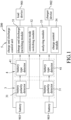
FIG. 1 is a block diagram illustrating a first embodiment of a battery charge and discharge protection device according to the disclosure; -
FIG. 2 is a circuit block diagram illustrating the first embodiment; -
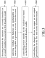
FIG. 3 is a flow chart illustrating a battery charge and discharge protection method performed by the first embodiment; -
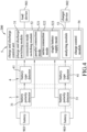
FIG. 4 is a block diagram illustrating a second embodiment of the battery charge and discharge protection device according to the disclosure; and -
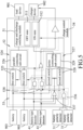
FIG. 5 is a circuit block diagram illustrating the second embodiment. - Before the disclosure is described in greater detail, it should be noted that where considered appropriate, reference numerals or terminal portions of reference numerals have been repeated among the figures to indicate corresponding or analogous elements, which may optionally have similar characteristics.
- Referring to
FIGS. 1 and2 , a first embodiment of a battery charge anddischarge protection device 200 according to the disclosure is adapted to be coupled to aload device 901 and acharger device 902, and is adapted to be installed with two ormore batteries 903. Each of thebatteries 903 may be non-rechargeable or rechargeable. The battery charge anddischarge protection device 200 controls power transfer among theload device 901, thecharger device 902 and thebatteries 903 based on detection results of, with respect to each of thebatteries 903, whether thebattery 903 is correctly installed or reversely installed and whether thebattery 903 is rechargeable or non-rechargeable. The battery charge anddischarge protection device 200 may be integrated with theload device 901 in an electronic product such as a speaker or a microphone, but the disclosure is not limited to such configurations. For illustration purposes, the battery charge anddischarge protection device 200 is installed with twobatteries 903 in this embodiment. - The battery charge and
discharge protection device 200 includes a battery polarity detecting unit 3 that is adapted to be coupled to thebatteries 903, a batterytype detecting unit 4 that is coupled to the battery polarity detecting unit 3, and a charge anddischarge control unit 5 that is coupled to the battery polarity detecting unit 3 and the batterytype detecting unit 4 and that is adapted to be further coupled to theload device 901, thecharger device 902 and thebatteries 903. In an example, the battery charge anddischarge protection device 200 further includes a battery holder (not shown) for accommodating thebatteries 903, and the battery polarity detecting unit 3 and the charge anddischarge control unit 5 are coupled to thebatteries 903 via the battery holder. Since there are many ways to implement the battery holder, and since the salient features of the disclosure does not reside in the battery holder, details of the battery holder are omitted herein for the sake of brevity. - The battery polarity detecting unit 3 includes two
battery polarity detectors 31 that respectively correspond to thebatteries 903. The batterytype detecting unit 4 includes twobattery type detectors 41 that respectively correspond to thebatteries 903. With respect to each of thebatteries 903, the correspondingbattery polarity detector 31 is coupled to thebattery 903, and the correspondingbattery type detector 41 is coupled to the correspondingbattery polarity detector 31. - With respect to each of the
batteries 903, the correspondingbattery polarity detector 31 detects whether thebattery 903 is correctly installed or reversely installed to generate a first detection signal, and connects thebattery 903 to or disconnects thebattery 903 from the correspondingbattery type detector 41 based on the first detection signal. When the correspondingbattery polarity detector 31 determines that thebattery 903 is reversely installed, the correspondingbattery polarity detector 31 causes the first detection signal to be at, for example, a logic "1" level, and disconnects thebattery 903 from the correspondingbattery type detector 41. When the correspondingbattery polarity detector 31 determines that thebattery 903 is correctly installed, the correspondingbattery polarity detector 31 causes the first detection signal to be at, for example, a logic "0" level, and connects thebattery 903 to the correspondingbattery type detector 41. The first detection signals that are respectively generated by thebattery polarity detectors 31 collectively constitute a first detection result. - Since there are many existing ways to implement the battery polarity detectors 31 (e.g., using diode circuits or transistor circuits to determine the polarities of the batteries 903), details of the
battery polarity detectors 31 are omitted herein for the sake of brevity. - With respect to each of the
batteries 903, the correspondingbattery type detector 41, when being connected to thebattery 903 by the correspondingbattery polarity detector 31, detects whether thebattery 903 is rechargeable or non-rechargeable to generate a type detection output. The type detection output includes a second detection signal, and an inverted second detection signal that is complementary to the second detection signal. When the correspondingbattery type detector 41 determines that thebattery 903 is rechargeable, the correspondingbattery type detector 41 causes the second detection signal to be at, for example, a logic "1" level, and causes the inverted second detection signal to be at, for example, a logic "0" level. When the correspondingbattery type detector 41 determines that thebattery 903 is non-rechargeable, the correspondingbattery type detector 41 causes the second detection signal to be at, for example, a logic "0" level, and causes the inverted second detection signal to be at, for example, a logic "1" level. The type detection outputs that are respectively generated by thebattery type detectors 41 collectively constitute a second detection result. - A voltage across a rechargeable battery is different from a voltage across a non-rechargeable battery in magnitude. For example, a voltage across a non-rechargeable zinc-carbon battery has a magnitude that falls within a range of from 0.6V to 1.5V, and a voltage across a rechargeable lithium-ion battery has a magnitude that falls within a range of from 3V to 4.2V. In this embodiment, each of the
battery type detectors 41 detects a voltage across thecorresponding battery 903, and determines, based on the voltage thus detected, whether thecorresponding battery 903 is rechargeable or non-rechargeable. However, the disclosure is not limited to such a configuration. Since there are many other ways to implement thebattery type detectors 41, and since the important features of the disclosure do not reside in the implementation of thebattery type detectors 41, other details of thebattery type detectors 41 are omitted herein for the sake of brevity. - The charge and
discharge control unit 5 includes a charge anddischarge switching module 51, a connectionmode switching module 52, ananalyzing module 53 and acharge control module 54. - The charge and
discharge switching module 51 is adapted to be coupled to theload device 901 and thecharger device 902, and is operable in a plurality of states that include anOFF state 511 and anON state 512. - The connection
mode switching module 52 is adapted to be coupled to thebatteries 903, is further coupled to the charge anddischarge switching module 51, and is operable in a plurality of connection modes that include aparallel connection mode 521 and aseries connection mode 522. - The charge and
discharge switching module 51 performs the following: (a) when operating in theOFF state 511, preventing transmission of power that is received from the connectionmode switching module 52 to theload device 901; and (b) when operating in theON state 512, permitting transmission of power that is received from the connectionmode switching module 52 to theload device 901 and transmission of power that is received from thecharger device 902 to the connectionmode switching module 52. - The connection
mode switching module 52 performs the following: (a) when operating in theparallel connection mode 521, connecting thebatteries 903 in parallel, and permitting transmission of power that is received from the parallel connectedbatteries 903 to the charge anddischarge switching module 51 and transmission of power that is received from the charge anddischarge switching module 51 to the parallel connectedbatteries 903; and (b) when operating in theseries connection mode 522, connecting thebatteries 903 in series, and permitting transmission of power that is received from the series connectedbatteries 903 to the charge anddischarge switching module 51. - The analyzing
module 53 is coupled to the battery polarity detecting unit 3 and the batterytype detecting unit 4 to receive the first and second detection results, and is further coupled to the charge anddischarge switching module 51 and the connectionmode switching module 52. Based on analysis of the first and second detection results, the analyzingmodule 53 controls switching of the charge anddischarge switching module 51 between theOFF state 511 and theON state 512 and switching of the connectionmode switching module 52 between theparallel connection mode 521 and theseries connection mode 522. - The
analyzing module 53 includes afirst logic circuit 531, asecond logic circuit 532, athird logic circuit 533 and afourth logic circuit 534. - The
first logic circuit 531 is coupled to thebattery polarity detectors 31 to receive the first detection signals, is further coupled to the charge anddischarge switching module 51, and generates, based on the first detection signals, a first logic signal that indicates whether both of thebatteries 903 are correctly installed and that is for receipt by the charge anddischarge switching module 51. The first logic signal causes the charge anddischarge switching module 51 to operate in theON state 512 when indicating that both of thebatteries 903 are correctly installed, and causes the charge anddischarge switching module 51 to operate in theOFF state 511 when indicating that thebatteries 903 are not both correctly installed (i.e., at least one of thebatteries 903 is reversely installed). In this embodiment, thefirst logic circuit 531 includes an OR gate. The OR gate has two input terminals that are respectively coupled to thebattery polarity detectors 31 to respectively receive the first detection signals, and an output terminal that is coupled to the charge anddischarge switching module 51 and that provides the first logic signal. When any one of the first detection signals is at the logic "1" level, the first logic signal is at a logic "1" level to indicate that thebatteries 903 are not both correctly installed. When both of the first detection signals are at the logic "0" level, the first logic signal is at a logic "0" level to indicate that both of thebatteries 903 are correctly installed. - The
second logic circuit 532 is coupled to thebattery type detectors 41 to receive the second detection signals, and generates, based on the second detection signals, a second logic signal that indicates whether both of thebatteries 903 are non-rechargeable. In this embodiment, thesecond logic circuit 532 includes an OR gate. The OR gate has two input terminals that are respectively coupled to thebattery type detectors 41 to respectively receive the second detection signals, and an output terminal that provides the second logic signal. When any one of the second detection signals is at the logic "1" level, the second logic signal is at a logic "1" level to indicate that thebatteries 903 are not both non-rechargeable (i.e., at least one of thebatteries 903 is rechargeable). When both of the second detection signals are at the logic "0" level, the second logic signal is at a logic "0" level to indicate that both of thebatteries 903 are non-rechargeable. - The
third logic circuit 533 is coupled to thebattery type detectors 41 to receive the inverted second detection signals, is further coupled to the connectionmode switching module 52, and generates, based on the inverted second detection signals, a third logic signal that indicates whether both of thebatteries 903 are rechargeable and that is for receipt by the connectionmode switching module 52. The third logic signal causes the connectionmode switching module 52 to operate in theseries connection mode 522 when indicating that thebatteries 903 are not both rechargeable (i.e., at least one of thebatteries 903 is non-rechargeable), and is dismissed as inconsequential when indicating that both of thebatteries 903 are rechargeable. In this embodiment, thethird logic circuit 533 includes an OR gate. The OR gate has two input terminals that are respectively coupled to thebattery type detectors 41 to respectively receive the inverted second detection signals, and an output terminal that is coupled to the connectionmode switching module 52 and that provides the third logic signal. When any one of the inverted second detection signals is at the logic "1" level, the third logic signal is at a logic "1" level to indicate that thebatteries 903 are not both rechargeable. When both of the inverting second detection signals are at the logic "0" level, the third logic signal is at a logic "0" level to indicate that both of thebatteries 903 are rechargeable. - The
fourth logic circuit 534 is coupled to the first to third logic circuits 531-533 to receive the first to third logic signals, is further coupled to the connectionmode switching module 52, and generates a fourth logic signal based on the first to third logic signals for receipt by the connectionmode switching module 52. The fourth logic signal causes the connectionmode switching module 52 to operate in theparallel connection mode 522 when all of the following conditions are met: the first logic signal indicates that both of thebatteries 903 are correctly installed; the second logic signal indicates that thebatteries 903 are not both non-rechargeable; and the third logic signal indicates that both of thebatteries 903 are rechargeable. The fourth logic signal does not matter when otherwise. - In this embodiment, the
fourth logic circuit 534 includes a first inverter, a second inverter and an AND gate. The first inverter has an input terminal that is coupled to the output terminal of the OR gate of thefirst logic circuit 531, and an output terminal. The second inverter has an input terminal that is coupled to the output terminal of the OR gate of thethird logic circuit 533, and an output terminal. The AND gate has three input terminals that are respectively coupled to the output terminal of the OR gate of thesecond logic circuit 532, the output terminal of the first inverter and the output terminal of the second inverter. The AND gate further has an output terminal that is coupled to the connectionmode switching module 52 and that provides the fourth logic signal. When the first detection result indicates that both of thebatteries 903 are correctly installed and the second detection result indicates that both of thebatteries 903 are rechargeable, the first logic signal is at the logic "0" level, the second logic signal is at the logic "1" level, the third logic signal is at the logic "0" level, and the fourth logic signal is at a logic "1" level so as to cause the connectionmode switching module 52 to operate in theparallel connection mode 521. When the first detection result indicates that both of thebatteries 903 are correctly installed and the second detection result indicates that only one of thebatteries 903 is rechargeable, the first logic signal is at the logic "0" level, the second logic signal is at the logic "1" level, the third logic signal is at the logic "1" level so as to cause the connectionmode switching module 52 to operate in theseries connection mode 522, and the fourth logic signal is at a logic "0" level. When the first detection result indicates that both of thebatteries 903 are correctly installed and the second detection result indicates that both of thebatteries 903 are non-rechargeable, the first logic signal is at the logic "0" level, the second logic signal is at the logic "0" level, the third logic signal is at the logic "1" level so as to cause the connectionmode switching module 52 to operate in theseries connection mode 522, and the fourth logic signal is at the logic "0" level. - The
charge control module 54 is adapted to be coupled to thecharger device 902, is further coupled to thefourth logic circuit 534 to receive the fourth logic signal, controls thecharger device 902 to output power to the charge and discharge switchingmodule 51 when the fourth logic signal causes the connectionmode switching module 52 to operate in the parallel connection mode 521 (i.e., the fourth logic signal is at the logic "1" level), and controls thecharger device 902 to not output power to the charge and discharge switchingmodule 51 when otherwise (i.e., the fourth logic signal is at the logic "0" level). In this embodiment, thecharge control module 54 includes a buffer. The buffer has an input terminal that is coupled to the output terminal of the AND gate of thefourth logic circuit 534 to receive the fourth logic signal, and an output terminal that is adapted to be coupled to thecharger device 902 and that provides an output control signal. When the fourth logic signal is at the logic "1" level, the output control signal is at a logic "1" level so as to cause thecharger device 902 to output power to the charge and discharge switchingmodule 51. When the fourth logic signal is at the logic "0" level, the output control signal is at a logic "0" level so as to cause thecharger device 902 to not output power to the charge and discharge switchingmodule 51. - Referring to
FIGS, 1 ,2 and3 , a battery charge and discharge protection method performed by the battery charge anddischarge protection device 200 of this embodiment includes the following steps. - In
step 801, the battery polarity detecting unit 3 detects, with respect to each of thebatteries 903, whether thebattery 903 is correctly installed or reversely installed, so as to generate the first detection result. In addition, with respect to each of thebatteries 903, the battery polarity detecting unit 3 connects thebattery 903 to the batterytype detecting unit 4 when the first detection result indicates that thebattery 903 is correctly installed. - In
step 802, the batterytype detecting unit 4, when being connected to any one of thebatteries 903 by the battery polarity detecting unit 3, detects whether thebattery 903 is rechargeable or non-rechargeable, so as to generate the second detection result. - In
step 803, the charge anddischarge control unit 5 controls power transfer to theload device 901 based on the first and second detection results. - In
step 804, the charge anddischarge control unit 5 controls thecharger device 902 to output or not output power to the charge anddischarge control unit 5 based on the first and second detection results. - To be specific, when the analyzing
module 53 determines based on the first detection result that at least one of thebatteries 903 is reversely installed, the analyzingmodule 53 controls the charge and discharge switchingmodule 51 to operate in theOFF state 511, and controls, via thecharge control module 54, thecharger device 902 to not output power, so as to disable power transfer from thebatteries 903 to theload device 901 and power transfer from thecharger device 902 to thebatteries 903. Therefore, both of thebatteries 903 are neither supplying power to theload device 901, nor being charged by thecharger device 902. When the analyzingmodule 53 determines based on the first detection result that both of thebatteries 903 are correctly installed and determines based on the second detection result that both of thebatteries 903 are rechargeable, the analyzingmodule 53 controls the charge and discharge switchingmodule 51 to operate in theON state 512, controls the connectionmode switching module 52 to operate in theparallel connection mode 521, and controls, via thecharge control module 54, thecharger device 902 to output power, so as to connect thebatteries 903 in parallel, and enable power transfer from the parallelconnected batteries 903 to theload device 901 and power transfer from thecharger device 902 to the parallelconnected batteries 903. Therefore, both of thebatteries 903 are supplying power to theload device 901, and are being charged by thecharger device 902. When the analyzingmodule 53 determines based on the first detection result that both of thebatteries 903 are correctly installed and determines based on the second detection result that at least one of thebatteries 903 is non-rechargeable, the analyzingmodule 53 controls the charge and discharge switchingmodule 51 to operate in theON state 512, controls the connectionmode switching module 52 to operate in theseries connection mode 522, and controls, via thecharge control module 54, thecharger device 902 to not output power, so as to connect thebatteries 903 in series, enable power transfer from the series connectedbatteries 903 to theload device 901, and disable power transfer from thecharger device 902 to the series connectedbatteries 903. Therefore, both of thebatteries 903 are supplying power to theload device 901, and none of thebatteries 903 are being charged by thecharger device 902. - In view of the above, the battery charge and
discharge protection device 200 of this embodiment prevents thebatteries 903 from supplying power to theload device 901 when at least one of thebatteries 903 is reversely installed. In addition, when both of thebatteries 903 are correctly installed, based on the types of thebatteries 903, the battery charge anddischarge protection device 200 of this embodiment automatically connects thebatteries 903 in parallel or in series, and automatically determines whether to charge thebatteries 903 or not. - It should be noted that this embodiment is described in detail from a scenario where the battery charge and
discharge protection device 200 is installed with twobatteries 903. However, the number of thebatteries 903 is not limited to two, and can be increased. When the number of thebatteries 903 is increased, the number of thebattery polarity detectors 31 and the number of thebattery type detectors 41 should be increased as well. - In addition, the analyzing
module 53 is not limited to the aforesaid configuration. There are many other ways to implement the analyzingmodule 53. For example, the analyzingmodule 53 may be implemented using transistor circuits and/or a combination of a microprocessor and software. - Referring to
FIGS. 4 and5 , a second embodiment of the battery charge anddischarge protection device 200 according to the disclosure is similar to the first embodiment, but differs from the first embodiment in what will be described below. - In the second embodiment, with respect to each of the
battery polarity detectors 31, the first detection signal generated by thebattery polarity detector 31 is at the logic "1" level when thebattery polarity detector 31 determines that thecorresponding battery 903 is correctly installed, and is at the logic "0" level when thebattery polarity detector 31 determines that thecorresponding battery 903 is reversely installed. - The connection modes further include a single
battery supply mode 523, and the connectionmode switching module 52 includes a parallelconnection mode circuit 524 and a seriesconnection mode circuit 527. - The parallel
connection mode circuit 524 includes twofirst switches 525 that respectively correspond to thebatteries 903, and a parallel connectingsub-circuit 526. Each of thefirst switches 525 is adapted to be coupled to thecorresponding battery 903. The parallel connecting sub-circuit 526 is coupled to thefirst switches 525 and the charge and discharge switchingmodule 51. - The series
connection mode circuit 527 includes twosecond switches 528 that respectively correspond to thebatteries 903, and aseries connecting sub-circuit 529. Each of thesecond switches 528 is adapted to be coupled to thecorresponding battery 903. Theseries connecting sub-circuit 529 is coupled to thesecond switches 528 and the charge and discharge switchingmodule 51. - The analyzing
module 53 includes afirst logic circuit 536, asecond logic circuit 537 and twothird logic circuits 538. - The
first logic circuit 536 is coupled to thebattery polarity detectors 31 to receive the first detection signals, is further coupled to the charge and discharge switchingmodule 51, and generates, based on the first detection signals, a first logic signal that indicates whether both of thebatteries 903 are correctly installed and that is for receipt by the charge and discharge switchingmodule 51. The first logic signal causes the charge and discharge switchingmodule 51 to operate in theON state 512 when indicating that both of thebatteries 903 are correctly installed, and causes the charge and discharge switchingmodule 51 to operate in theOFF state 511 when indicating that thebatteries 903 are not both correctly installed (i.e., at least one of thebatteries 903 is reversely installed). In this embodiment, thefirst logic circuit 536 includes an AND gate. The AND gate has two input terminals that are respectively coupled to thebattery polarity detectors 31 to respectively receive the first detection signals, and an output terminal that is coupled to the charge and discharge switchingmodule 51 and that provides the first logic signal. When both of the first detection signals are at the logic "1" level, the first logic signal is at a logic "1" level to indicate that both of thebatteries 903 are correctly installed. When any one of the first detection signals is at the logic "0" level, the first logic signal is at a logic "0" level to indicate that thebatteries 903 are not both correctly installed. - The
second logic circuit 537 is coupled to thebattery type detectors 41 to receive the second detection signals, is further coupled to thesecond switches 528, and generates, based on the second detection signals, a second logic signal that indicates whether both of thebatteries 903 are non-rechargeable and that is for receipt by the second switches 528. The second logic signal causes thesecond switches 528 to conduct (i.e., causing the connectionmode switching module 52 to operate in the series connection mode 522) when indicating that both of thebatteries 903 are non-rechargeable, and causes thesecond switches 528 to not conduct when indicating that thebatteries 903 are not both non-rechargeable (i.e., at least one of thebatteries 903 is rechargeable). When both of thesecond switches 528 conduct, thesecond switches 528 respectively connect thebatteries 903 to theseries connecting sub-circuit 529, and theseries connecting sub-circuit 529 connects thebatteries 903 in series, and permits transmission of power that is received from the series connectedbatteries 903 to the charge and discharge switchingmodule 51. In this embodiment, thesecond logic circuit 537 includes a NOR gate. The NOR gate has two input terminals that are respectively coupled to thebattery type detectors 41 to respectively receive the second detection signals, and an output terminal that is coupled to thesecond switches 528 and that provides the second logic signal. When both of the second detection signals are at the logic "0" level, the second logic signal is at a logic "1" level to indicate that both of thebatteries 903 are non-rechargeable. When any one of the second detection signals is at the logic "1" level, the second logic signal is at a logic "0" level to indicate that thebatteries 903 are not both non-rechargeable. - The
third logic circuits 538 respectively correspond to thebatteries 903. With respect to each of thebatteries 903, the correspondingthird logic circuit 538 is coupled to thefirst logic circuit 536 and the correspondingbattery type detector 41 to receive the first logic signal and the second detection signal, is further coupled to the correspondingfirst switch 525, and generates, based on the first logic signal and the second detection signal, a third logic signal that is for receipt by the correspondingfirst switch 525 and that controls switching of the correspondingfirst switch 525 between conduction and non-conduction. In this embodiment, the correspondingthird logic circuit 538 includes an AND gate. The AND gate has two input terminals that are respectively coupled to thefirst logic circuit 536 and the correspondingbattery type detector 41 to respectively receive the first logic signal and the second detection signal, and an output terminal that is coupled to the correspondingfirst switch 525 and that provides the third logic signal. When both of the first logic signal and the second detection signal are at the logic "1" level, the third logic signal is at a logic "1" level so as to cause the correspondingfirst switch 525 to conduct. When any one of the first logic signal and the second detection signal is at the logic "0" level, the third logic signal is at a logic "0" level so as to cause the correspondingfirst switch 525 to not conduct. - Therefore, when the first logic signal indicates that both of the
batteries 903 are correctly installed and the second detection signals collectively indicate that both of thebatteries 903 are rechargeable, the third logic signals that are respectively generated by thethird logic circuits 538 respectively cause thefirst switches 525 to conduct (i.e., collectively causing the connectionmode switching module 52 to operate in the parallel connection mode 521). When the first logic signal indicates that both of thebatteries 903 are correctly installed and the second detection signals collectively indicate that only one of thebatteries 903 is rechargeable, the third logic signals will cause only one of thefirst switches 525 to conduct (i.e., collectively causing the connectionmode switching module 52 to operate in the single battery supply mode 523). Otherwise, the third logic signals respectively cause thefirst switches 525 to not conduct. - When both of the
first switches 525 conduct, thefirst switches 525 respectively connect thebatteries 903 to the parallel connecting sub-circuit 526, and the parallel connecting sub-circuit 526 connects thebatteries 903 in parallel, permits transmission of power that is received from the parallelconnected batteries 903 to the charge and discharge switchingmodule 51, and permits transmission of power that is received from the charge and discharge switchingmodule 51 to the parallelconnected batteries 903. When only one of thefirst switches 525 conducts, the conductingfirst switch 525 connects thecorresponding battery 903 to the parallel connecting sub-circuit 526, the non-conductingfirst switch 525 disconnects thecorresponding battery 903 from the parallel connecting sub-circuit 526, and the parallel connecting sub-circuit 526 permits transmission of power, that is, permitting power received from thebattery 903 connected to the parallel connecting sub-circuit 526 to transmit to the charge and discharge switchingmodule 51 and power received from the charge and discharge switchingmodule 51 to transmit to thebattery 903 that is connected to the parallel connectingsub-circuit 526. - The
charge control module 54 is coupled to thethird logic circuits 538 to receive the third logic signals, controls thecharger device 902 to output power to the charge and discharge switchingmodule 51 when the third logic signals collectively cause the connectionmode switching module 52 to operate in any one of theparallel connection mode 521 and the singlebattery supply mode 523, and controls thecharger device 902 to not output power to the charge and discharge switchingmodule 51 when otherwise. In this embodiment, thecharge control module 54 includes a NOR gate and a buffer. The NOR gate has two input terminals that are respectively coupled to the output terminals of the AND gates of thethird logic circuits 538 to respectively receive the third logic signals, and an output terminal. The buffer has an input terminal that is coupled to the output terminal of the NOR gate, and an output terminal that is adapted to be coupled to thecharger device 902 and that provides an output control signal. When any one of the third logic signals is at the logic "1" level, the output control signal is at a logic "0" level so as to cause thecharger device 902 to output power to the charge and discharge switchingmodule 51. When both of the third logic signals are at the logic "0" level, the output control signal is at a logic "1" level so as to cause thecharger device 902 to not output power to the charge and discharge switchingmodule 51. - Therefore, when the analyzing
module 53 determines based on the first detection result that at least one of thebatteries 903 is reversely installed, the analyzingmodule 53 controls the charge and discharge switchingmodule 51 to operate in theOFF state 511, and controls, via thecharge control module 54, thecharger device 902 to not output power, so as to disable power transfer from thebatteries 903 to theload device 901 and power transfer from thecharger device 902 to thebatteries 903. Therefore, both of thebatteries 903 are neither supplying power to theload device 901, nor being charged by thecharger device 902. When the analyzingmodule 53 determines based on the first detection result that both of thebatteries 903 are correctly installed and determines based on the second detection result that both of thebatteries 903 are rechargeable, the analyzingmodule 53 controls the charge and discharge switchingmodule 51 to operate in theON state 512, controls the connectionmode switching module 52 to operate in theparallel connection mode 521, and controls, via thecharge control module 54, thecharger device 902 to output power, so as to connect thebatteries 903 in parallel, and enable power transfer from the parallelconnected batteries 903 to theload device 901 and power transfer from thecharger device 902 to the parallelconnected batteries 903. Therefore, both of thebatteries 903 are supplying power to theload device 901, and are being charged by thecharger device 902. When the analyzingmodule 53 determines based on the first detection result that both of thebatteries 903 are correctly installed and determines based on the second detection result that only one of thebatteries 903 is rechargeable, the analyzingmodule 53 controls the charge and discharge switchingmodule 51 to operate in theON state 512, controls the connectionmode switching module 52 to operate in the singlebattery supply mode 523, and controls, via thecharge control module 54, thecharger device 902 to output power, so as to enable power transfer from thebattery 903 that is determined to be rechargeable to theload device 901 and power transfer from thecharger device 902 to thebattery 903 that is determined to be rechargeable. Therefore, only thebattery 903 that is determined to be rechargeable is supplying power to theload device 901, and is being charged by thecharger device 902. When the analyzingmodule 53 determines based on the first detection result that both of thebatteries 903 are correctly installed and determines based on the second detection result that both of thebatteries 903 are non-rechargeable, the analyzingmodule 53 controls the charge and discharge switchingmodule 51 to operate in theON state 512, controls the connectionmode switching module 52 to operate in theseries connection mode 522, and controls, via thecharge control module 54, thecharger device 902 to not output power, so as to connect thebatteries 903 in series, enable power transfer from the series connectedbatteries 903 to theload device 901, and disable power transfer from thecharger device 902 to the series connectedbatteries 903. Therefore, both of thebatteries 903 are supplying power to theload device 901, and none of thebatteries 903 are being charged by thecharger device 902. - In view of the above, since the battery charge and
discharge protection device 200 of this embodiment prevents thebatteries 903 from supplying power to theload device 901 when at least one of thebatteries 903 is reversely installed, theload device 901 would not be damaged by the reversely installed battery(ies) 903, if any. In addition, in a scenario where both of thebatteries 903 are correctly installed, the battery charge anddischarge protection device 200 of this embodiment performs one of the following actions based on the types of the batteries 903: when both of thebatteries 903 are rechargeable, connecting thebatteries 903 in parallel, and permitting the parallelconnected batteries 903 to supply power to theload device 903; when only one of thebatteries 903 is rechargeable, permitting therechargeable battery 903 to supply power to theload device 903; and when both of thebatteries 903 are non-rechargeable, connecting thebatteries 903 in series, and permitting the series connectedbatteries 903 to supply power to theload device 903, thereby optimizing power transfer from thebatteries 903 to theload device 903. Moreover, in the aforesaid scenario, when any one of thebatteries 903 is rechargeable, the battery charge anddischarge protection device 200 of this embodiment controls thecharger device 902 to output power, and uses the power outputted by thecharger device 902 to charge the rechargeable battery(ies) 903. - In the description above, for the purposes of explanation, numerous specific details have been set forth in order to provide a thorough understanding of the embodiments. It will be apparent, however, to one skilled in the art, that one or more other embodiments may be practiced without some of these specific details. It should also be appreciated that reference throughout this specification to "one embodiment," "an embodiment," an embodiment with an indication of an ordinal number and so forth means that a particular feature, structure, or characteristic may be included in the practice of the disclosure. It should be further appreciated that in the description, various features are sometimes grouped together in a single embodiment, figure, or description thereof for the purpose of streamlining the disclosure and aiding in the understanding of various inventive aspects, and that one or more features or specific details from one embodiment may be practiced together with one or more features or specific details from another embodiment, where appropriate, in the practice of the disclosure.
Claims (7)
- A battery charge and discharge protection device (200) adapted to be coupled to a load device (901) and a charger device (902), and adapted to be installed with two batteries (903), said battery charge and discharge protection device (200) being characterized by comprising:a battery polarity detecting unit (3) adapted to be coupled to the batteries (903), and configured to detect, with respect to each of the batteries (903), whether the battery (903) is correctly installed or reversely installed, so as to generate a first detection result;a battery type detecting unit (4) disposed and configured to detect, with respect to each of the batteries (903), whether the battery (903) is rechargeable or non-rechargeable, so as to generate a second detection result; anda charge and discharge control unit (5) coupled to said battery polarity detecting unit (3) and said battery type detecting unit (4) being adapted to receive the first and second detection results, and adapted to be further coupled to the load device (901), the charger device (902) and the batteries (903);when said charge and discharge control unit (5) determines based on the first detection result that at least one of the batteries (903) is reversely installed, said charge and discharge control unit (5) disabling power transfer from the batteries (903) to the load device (901), and disabling power transfer from the charger device (902) to the batteries (903);when said charge and discharge control unit (5) determines based on the first detection result that both of the batteries (903) are correctly installed and determines based on the second detection result that both of the batteries (903) are rechargeable, said charge and discharge control unit (5) connecting the batteries (903) in parallel, enabling power transfer from the batteries (903) that have been connected in parallel to the load device (901), and enabling power transfer from the charger device (902) to the batteries (903) that have been connected in parallel;when said charge and discharge control unit (5) determines based on the first detection result that both of the batteries (903) are correctly installed and determines based on the second detection result that only one of the batteries (903) is rechargeable, said charge and discharge control unit (5) enabling power transfer from the battery (903) that is determined to be rechargeable to the load device (901), and enabling power transfer from the charger device (902) to the battery (903) that is determined to be rechargeable.
- The battery charge and discharge protection device (200) of claim 1, characterized in that said charge and discharge control unit (5) includes:a charge and discharge switching module (51) adapted to be coupled to the load device (901) and the charger device (902), and operable in a plurality of states that include an OFF state (511) and an ON state (512);a connection mode switching module (52) adapted to be coupled to the batteries (903), further coupled to said charge and discharge switching module (51), and operable in a plurality of connection modes that include a parallel connection mode (521) and a single battery supply mode (523);said charge and discharge switching module (51), when operating in the OFF state (511), preventing transmission of power that is received from said connection mode switching module (52) to the load device (901);said charge and discharge switching module (51), when operating in the ON state (512), permitting transmission of power that is received from said connection mode switching module (52) to the load device (901) and transmission of power that is received from the charger device (902) to said connection mode switching module (52);when said connection mode switching module (52) operates in the parallel connection mode (521), said connection mode switching module (52) connecting the batteries (903) in parallel, and permitting transmission of power that is received from the batteries (903) that have been connected in parallel to said charge and discharge switching module (51) and transmission of power that is received from said charge and discharge switching module (51) to the batteries (903) that have been connected in parallel;when said connection mode switching module (52) operates in the single battery supply mode (523), said connection mode switching module (52) permitting transmission of power that is received from the battery (903) determined to be rechargeable to said charge and discharge switching module (51) and transmission of power that is received from said charge and discharge switching module (51) to the battery (903) that is determined to be rechargeable; andan analyzing module (53) coupled to said battery polarity detecting unit (3) and said battery type detecting unit (4) being adaptedto receive the first and second
detection results, and further coupled to said charge and discharge switching module (51) and said connection mode switching module (52);said analyzing module (53) controlling, based on analysis of the first and second detection results, switching of said charge and discharge switching module (51) between the OFF state (511) and the ON state (512) and switching of said connection mode switching module (52) between the parallel connection mode (521) and the single battery supply mode (523). - The battery charge and discharge protection device (200) of claim 2, characterized in that:the connection modes further includes a series connection mode (522);when said connection mode switching module (52) operates in the series connection mode (522), said connection mode switching module (52) connects the batteries (903) in series, and permits transmission of power that is received from the batteries (903) that have been connected in series to said charge and discharge switching module (51);said analyzing module (53), when determining based on the first detection result that both of the batteries (903) are correctly installed and determining based on the second detection result that both of the batteries (903) are non-rechargeable, controls said connection mode switching module (52) to operate in the series connection mode (522);said charge and discharge control unit (5) further includes a charge control module (54) that is adapted to be coupled to the charger device (902) and that is further coupled to said analyzing module (53);when said analyzing module (53) controls said connection mode switching module (52) to operate in any one of the parallel connection mode (521) and the single battery supply mode (523), said charge control module (54) controls the charger device (902) to output power to said charge and discharge switching module (51).
- The battery charge and discharge protection device (200) of claim 3, characterized in that:the second detection result includes two second detection signals which respectively correspond to the batteries (903), and each of which indicates whether the battery (903) that corresponds to the second detection signal is rechargeable or non-rechargeable; andsaid analyzing module (53) includesa first logic circuit (536) coupled to said battery polarity detecting unit (3) to receive the first detection result, further coupled to said charge and discharge switching module (51), and generating, based on the first detection result, a first logic signal that indicates whether both of the batteries (903) are correctly installed and that is for receipt by said charge and discharge switching module (51),the first logic signal, when indicating that both of the batteries (903) are correctly installed, causing said charge and discharge switching module (51) to operate in the ON state (512),a second logic circuit (537) coupled to said battery type detecting unit (4) to receive the second detection result, further coupled to said connection mode switching module (52), and generating, based on the second detection result, a second logic signal that indicates whether both of the batteries (903) are non-rechargeable and that is for receipt by said connection mode switching module (52),the second logic signal, when indicating that both of the batteries (903) are non-rechargeable, causing said connection mode switching module (52) to operate in the series connection mode (522), andtwo third logic circuits (538) respectively corresponding to the batteries (903),with respect to each of the batteries (903), said third logic circuit (538) that corresponds to the battery (903) being coupled to said first logic circuit (536) and said battery type detecting unit (4) to receive the first logic signal and the second detection signal that corresponds to the battery (903), being further coupled to said connection mode switching module (52), and generating a third logic signal for receipt by said connection mode switching module (52) based on the first logic signal and the second detection signal that corresponds to the battery (903),when the first logic signal indicates that both of the batteries (903) are correctly installed, and when the second detection signals collectively indicate that both of the batteries (903) are rechargeable, the third logic signals that are respectively generated by said third logic circuits (538) collectively causing said connection mode switching module (52) to operate in the parallel connection mode (521),when the first logic signal indicates that both of the batteries (903) are correctly installed, and when the second detection signals collectively indicate that only one of the batteries (903) is rechargeable, the third logic signals that are respectively generated by said third logic circuits (538) collectively causing said connection mode switching module (52) to operate in the single battery supply mode (523).
- The battery charge and discharge protection device (200) of claim 4, characterized in that:said connection mode switching module (52) includes a series connection mode circuit (527) and a parallel connection mode circuit (524);each of said series connection mode circuit (527) and said parallel connection mode circuit (524) is adapted to be coupled to the batteries (903), and is further coupled to said charge and discharge switching module (51);when said connection mode switching module (52) operates in the series connection mode (522), said series connection mode circuit (527) connects the batteries (903) in series, and permits transmission of power that is received from the batteries (903) that have been connected in series to said charge and discharge switching module (51);said parallel connection mode circuit (524) includes two first switches (525) that are adapted to be respectively coupled to the batteries (903), and a parallel connecting sub-circuit (526) that is coupled to said first switches (525) and said charge and discharge switching module (51);each of said first switch (525) is further coupled to said third logic circuit (538) that corresponds to the battery (903) coupled to said first switch (525) to receive the third logic signal, and conducts to connect the battery (903) that is coupled to said first switch (525) to said parallel connecting sub-circuit (526) when the third logic signal indicates that both of the batteries (903) are correctly installed and that the battery (903) coupled to said first switch (525) is rechargeable;when both of said first switches (525) conduct, said parallel connecting sub-circuit (526) connects the batteries (903) in parallel, and permits transmission of power that is received from the batteries (903) that have been connected in parallel to said charge and discharge switching module (51) and transmission of power that is received from said charge and discharge switching module (51) to the batteries (903) that have been connected in parallel;when only one of said first switches (525) conducts, said parallel connecting sub-circuit (526) permits transmission of power that is received from the battery (903) connected to said parallel connecting sub-circuit (526) to said charge and discharge switching module (51) and transmission of power that is received from said charge and discharge switching module (51) to the battery (903) that is connected to said parallel connecting sub-circuit (526).
- The battery charge and discharge protection device (200) of claim 5, characterized in that:said series connection mode circuit (527) includes two second switches (528) that are adapted to be respectively coupled to the batteries (903), and a series connecting sub-circuit (529) that is coupled to said second switches (528) and said charge and discharge switching module (51);each of said second switches (528) is further coupled to said second logic circuit (537) to receive the second logic signal, and conducts to connect the battery (903) that is coupled to said second switch (528) to said series connecting sub-circuit (529) when the second logic signal indicates that both of the batteries (903) are non-rechargeable;when both of said second switches (528) conduct, said series connecting sub-circuit (529) connects the batteries (903) in series, and permits transmission of power that is received from the batteries (903) that have been connected in series to said charge and discharge switching module (51).
- The battery charge and discharge protection device (200) of any of claims 4 to 6, characterized in that said charge control module (54) is coupled to said third logic circuits (538) to receive the third logic signals, and controls the charger device (902) to output power to said charge and discharge switching module (51) when the third logic signals collectively cause said connection mode switching module (52) to operate in any one of the parallel connection mode (521) and the single battery supply mode (523).
Priority Applications (1)
| Application Number | Priority Date | Filing Date | Title |
|---|---|---|---|
| EP22213958.6A EP4254716B1 (en) | 2022-03-22 | 2022-03-22 | Battery charge and discharge protection device and method |
Applications Claiming Priority (2)
| Application Number | Priority Date | Filing Date | Title |
|---|---|---|---|
| EP22163554.3A EP4250517B1 (en) | 2022-03-22 | 2022-03-22 | Battery charge and discharge protection device and method |
| EP22213958.6A EP4254716B1 (en) | 2022-03-22 | 2022-03-22 | Battery charge and discharge protection device and method |
Related Parent Applications (2)
| Application Number | Title | Priority Date | Filing Date |
|---|---|---|---|
| EP22163554.3A Division-Into EP4250517B1 (en) | 2022-03-22 | 2022-03-22 | Battery charge and discharge protection device and method |
| EP22163554.3A Division EP4250517B1 (en) | 2022-03-22 | 2022-03-22 | Battery charge and discharge protection device and method |
Publications (3)
| Publication Number | Publication Date |
|---|---|
| EP4254716A1 EP4254716A1 (en) | 2023-10-04 |
| EP4254716C0 EP4254716C0 (en) | 2024-07-03 |
| EP4254716B1 true EP4254716B1 (en) | 2024-07-03 |
Family
ID=80930075
Family Applications (2)
| Application Number | Title | Priority Date | Filing Date |
|---|---|---|---|
| EP22163554.3A Active EP4250517B1 (en) | 2022-03-22 | 2022-03-22 | Battery charge and discharge protection device and method |
| EP22213958.6A Active EP4254716B1 (en) | 2022-03-22 | 2022-03-22 | Battery charge and discharge protection device and method |
Family Applications Before (1)
| Application Number | Title | Priority Date | Filing Date |
|---|---|---|---|
| EP22163554.3A Active EP4250517B1 (en) | 2022-03-22 | 2022-03-22 | Battery charge and discharge protection device and method |
Country Status (1)
| Country | Link |
|---|---|
| EP (2) | EP4250517B1 (en) |
Families Citing this family (1)
| Publication number | Priority date | Publication date | Assignee | Title |
|---|---|---|---|---|
| DE102024201214A1 (en) * | 2024-02-09 | 2025-08-14 | Shimano Inc. | Component for a human-powered vehicle |
Family Cites Families (3)
| Publication number | Priority date | Publication date | Assignee | Title |
|---|---|---|---|---|
| US10784680B2 (en) * | 2015-01-23 | 2020-09-22 | Elevate Technologies Corporation | Adaptable recharging and lighting station and methods of using the same |
| US12040638B2 (en) * | 2018-10-03 | 2024-07-16 | Switching Battery Inc. | Energy storage system and method to improve battery performance by battery connection method |
| US11245272B2 (en) * | 2020-05-28 | 2022-02-08 | Fuyuan Electronic Co., Ltd | Output protector for charger |
-
2022
- 2022-03-22 EP EP22163554.3A patent/EP4250517B1/en active Active
- 2022-03-22 EP EP22213958.6A patent/EP4254716B1/en active Active
Also Published As
| Publication number | Publication date |
|---|---|
| EP4250517B1 (en) | 2025-09-10 |
| EP4254716C0 (en) | 2024-07-03 |
| EP4250517C0 (en) | 2025-09-10 |
| EP4250517A1 (en) | 2023-09-27 |
| EP4254716A1 (en) | 2023-10-04 |
Similar Documents
| Publication | Publication Date | Title |
|---|---|---|
| US6624614B2 (en) | Charge and discharge controller | |
| US9035618B2 (en) | Battery pack and method of controlling the same | |
| US6639387B2 (en) | Battery pack and inspection device therefor | |
| CN107894567B (en) | Battery pack and battery pack interface state detection system and detection method | |
| US5789900A (en) | Device for protecting a secondary battery from overcharge and overdischarge | |
| KR100281534B1 (en) | Battery pack selection circuit of portable computer | |
| KR101182890B1 (en) | System for controlling charging of battery pack | |
| US8471526B2 (en) | Protection device for secondary batteries, and battery pack and electronic equipment employing same | |
| US8698459B2 (en) | Battery pack and method of controlling the same | |
| US20120256598A1 (en) | Battery Pack Detection Circuit | |
| KR101201139B1 (en) | Protection circuit device of battery pack | |
| US12170452B2 (en) | Charging system and charger for reducing inrush current | |
| EP3771057B1 (en) | Cell protection circuit and electronic device | |
| JP2004120849A (en) | Secondary battery unit with external protection circuit | |
| EP3772153B1 (en) | Battery protection system | |
| EP4254716B1 (en) | Battery charge and discharge protection device and method | |
| KR102117315B1 (en) | Battery apparatus | |
| KR20160094225A (en) | Overcharge Protection Apparatus for Battery Pack and Overcharge Protection System | |
| KR102332335B1 (en) | Battery pack | |
| EP3043441B1 (en) | Battery management unit for preventing performance of erroneous control algorithm from communication error | |
| US12176741B2 (en) | Battery charge and discharge protection device and method | |
| US20200044462A1 (en) | Charge system, battery pack, and protection apparatus | |
| KR101213479B1 (en) | A battery pack and a charging system including the battery pack and method for controlling the charging system | |
| CN209881442U (en) | Battery pack | |
| KR102812086B1 (en) | Battery charge and discharge protection device and method |
Legal Events
| Date | Code | Title | Description |
|---|---|---|---|
| PUAI | Public reference made under article 153(3) epc to a published international application that has entered the european phase |
Free format text: ORIGINAL CODE: 0009012 |
|
| STAA | Information on the status of an ep patent application or granted ep patent |
Free format text: STATUS: REQUEST FOR EXAMINATION WAS MADE |
|
| 17P | Request for examination filed |
Effective date: 20230704 |
|
| AC | Divisional application: reference to earlier application |
Ref document number: 4250517 Country of ref document: EP Kind code of ref document: P |
|
| AK | Designated contracting states |
Kind code of ref document: A1 Designated state(s): AL AT BE BG CH CY CZ DE DK EE ES FI FR GB GR HR HU IE IS IT LI LT LU LV MC MK MT NL NO PL PT RO RS SE SI SK SM TR |
|
| GRAP | Despatch of communication of intention to grant a patent |
Free format text: ORIGINAL CODE: EPIDOSNIGR1 |
|
| STAA | Information on the status of an ep patent application or granted ep patent |
Free format text: STATUS: GRANT OF PATENT IS INTENDED |
|
| INTG | Intention to grant announced |
Effective date: 20240402 |
|
| GRAS | Grant fee paid |
Free format text: ORIGINAL CODE: EPIDOSNIGR3 |
|
| GRAA | (expected) grant |
Free format text: ORIGINAL CODE: 0009210 |
|
| STAA | Information on the status of an ep patent application or granted ep patent |
Free format text: STATUS: THE PATENT HAS BEEN GRANTED |
|
| AC | Divisional application: reference to earlier application |
Ref document number: 4250517 Country of ref document: EP Kind code of ref document: P |
|
| AK | Designated contracting states |
Kind code of ref document: B1 Designated state(s): AL AT BE BG CH CY CZ DE DK EE ES FI FR GB GR HR HU IE IS IT LI LT LU LV MC MK MT NL NO PL PT RO RS SE SI SK SM TR |
|
| REG | Reference to a national code |
Ref country code: CH Ref legal event code: EP |
|
| REG | Reference to a national code |
Ref country code: DE Ref legal event code: R096 Ref document number: 602022004339 Country of ref document: DE |
|
| U01 | Request for unitary effect filed |
Effective date: 20240712 |
|
| U07 | Unitary effect registered |
Designated state(s): AT BE BG DE DK EE FI FR IT LT LU LV MT NL PT SE SI Effective date: 20240725 |
|
| PG25 | Lapsed in a contracting state [announced via postgrant information from national office to epo] |
Ref country code: NO Free format text: LAPSE BECAUSE OF FAILURE TO SUBMIT A TRANSLATION OF THE DESCRIPTION OR TO PAY THE FEE WITHIN THE PRESCRIBED TIME-LIMIT Effective date: 20241003 |
|
| PG25 | Lapsed in a contracting state [announced via postgrant information from national office to epo] |
Ref country code: PL Free format text: LAPSE BECAUSE OF FAILURE TO SUBMIT A TRANSLATION OF THE DESCRIPTION OR TO PAY THE FEE WITHIN THE PRESCRIBED TIME-LIMIT Effective date: 20240703 Ref country code: GR Free format text: LAPSE BECAUSE OF FAILURE TO SUBMIT A TRANSLATION OF THE DESCRIPTION OR TO PAY THE FEE WITHIN THE PRESCRIBED TIME-LIMIT Effective date: 20241004 |
|
| PG25 | Lapsed in a contracting state [announced via postgrant information from national office to epo] |
Ref country code: IS Free format text: LAPSE BECAUSE OF FAILURE TO SUBMIT A TRANSLATION OF THE DESCRIPTION OR TO PAY THE FEE WITHIN THE PRESCRIBED TIME-LIMIT Effective date: 20241103 |
|
| PG25 | Lapsed in a contracting state [announced via postgrant information from national office to epo] |
Ref country code: CZ Free format text: LAPSE BECAUSE OF FAILURE TO SUBMIT A TRANSLATION OF THE DESCRIPTION OR TO PAY THE FEE WITHIN THE PRESCRIBED TIME-LIMIT Effective date: 20240703 Ref country code: HR Free format text: LAPSE BECAUSE OF FAILURE TO SUBMIT A TRANSLATION OF THE DESCRIPTION OR TO PAY THE FEE WITHIN THE PRESCRIBED TIME-LIMIT Effective date: 20240703 |
|
| PG25 | Lapsed in a contracting state [announced via postgrant information from national office to epo] |
Ref country code: RS Free format text: LAPSE BECAUSE OF FAILURE TO SUBMIT A TRANSLATION OF THE DESCRIPTION OR TO PAY THE FEE WITHIN THE PRESCRIBED TIME-LIMIT Effective date: 20241003 Ref country code: ES Free format text: LAPSE BECAUSE OF FAILURE TO SUBMIT A TRANSLATION OF THE DESCRIPTION OR TO PAY THE FEE WITHIN THE PRESCRIBED TIME-LIMIT Effective date: 20240703 |
|
| PG25 | Lapsed in a contracting state [announced via postgrant information from national office to epo] |
Ref country code: RS Free format text: LAPSE BECAUSE OF FAILURE TO SUBMIT A TRANSLATION OF THE DESCRIPTION OR TO PAY THE FEE WITHIN THE PRESCRIBED TIME-LIMIT Effective date: 20241003 Ref country code: PL Free format text: LAPSE BECAUSE OF FAILURE TO SUBMIT A TRANSLATION OF THE DESCRIPTION OR TO PAY THE FEE WITHIN THE PRESCRIBED TIME-LIMIT Effective date: 20240703 Ref country code: NO Free format text: LAPSE BECAUSE OF FAILURE TO SUBMIT A TRANSLATION OF THE DESCRIPTION OR TO PAY THE FEE WITHIN THE PRESCRIBED TIME-LIMIT Effective date: 20241003 Ref country code: IS Free format text: LAPSE BECAUSE OF FAILURE TO SUBMIT A TRANSLATION OF THE DESCRIPTION OR TO PAY THE FEE WITHIN THE PRESCRIBED TIME-LIMIT Effective date: 20241103 Ref country code: HR Free format text: LAPSE BECAUSE OF FAILURE TO SUBMIT A TRANSLATION OF THE DESCRIPTION OR TO PAY THE FEE WITHIN THE PRESCRIBED TIME-LIMIT Effective date: 20240703 Ref country code: GR Free format text: LAPSE BECAUSE OF FAILURE TO SUBMIT A TRANSLATION OF THE DESCRIPTION OR TO PAY THE FEE WITHIN THE PRESCRIBED TIME-LIMIT Effective date: 20241004 Ref country code: ES Free format text: LAPSE BECAUSE OF FAILURE TO SUBMIT A TRANSLATION OF THE DESCRIPTION OR TO PAY THE FEE WITHIN THE PRESCRIBED TIME-LIMIT Effective date: 20240703 Ref country code: CZ Free format text: LAPSE BECAUSE OF FAILURE TO SUBMIT A TRANSLATION OF THE DESCRIPTION OR TO PAY THE FEE WITHIN THE PRESCRIBED TIME-LIMIT Effective date: 20240703 |
|
| U20 | Renewal fee for the european patent with unitary effect paid |
Year of fee payment: 4 Effective date: 20250113 |
|
| PG25 | Lapsed in a contracting state [announced via postgrant information from national office to epo] |
Ref country code: SM Free format text: LAPSE BECAUSE OF FAILURE TO SUBMIT A TRANSLATION OF THE DESCRIPTION OR TO PAY THE FEE WITHIN THE PRESCRIBED TIME-LIMIT Effective date: 20240703 |
|
| PG25 | Lapsed in a contracting state [announced via postgrant information from national office to epo] |
Ref country code: SK Free format text: LAPSE BECAUSE OF FAILURE TO SUBMIT A TRANSLATION OF THE DESCRIPTION OR TO PAY THE FEE WITHIN THE PRESCRIBED TIME-LIMIT Effective date: 20240703 |
|
| PLBE | No opposition filed within time limit |
Free format text: ORIGINAL CODE: 0009261 |
|
| STAA | Information on the status of an ep patent application or granted ep patent |
Free format text: STATUS: NO OPPOSITION FILED WITHIN TIME LIMIT |
|
| 26N | No opposition filed |
Effective date: 20250404 |
|
| PG25 | Lapsed in a contracting state [announced via postgrant information from national office to epo] |
Ref country code: MC Free format text: LAPSE BECAUSE OF FAILURE TO SUBMIT A TRANSLATION OF THE DESCRIPTION OR TO PAY THE FEE WITHIN THE PRESCRIBED TIME-LIMIT Effective date: 20240703 |
|
| REG | Reference to a national code |
Ref country code: CH Ref legal event code: H13 Free format text: ST27 STATUS EVENT CODE: U-0-0-H10-H13 (AS PROVIDED BY THE NATIONAL OFFICE) Effective date: 20251024 |
|
| PG25 | Lapsed in a contracting state [announced via postgrant information from national office to epo] |
Ref country code: CH Free format text: LAPSE BECAUSE OF NON-PAYMENT OF DUE FEES Effective date: 20250331 |
|
| PG25 | Lapsed in a contracting state [announced via postgrant information from national office to epo] |
Ref country code: IE Free format text: LAPSE BECAUSE OF NON-PAYMENT OF DUE FEES Effective date: 20250322 |
|
| U20 | Renewal fee for the european patent with unitary effect paid |
Year of fee payment: 5 Effective date: 20260113 |
|
| PG25 | Lapsed in a contracting state [announced via postgrant information from national office to epo] |
Ref country code: RO Free format text: LAPSE BECAUSE OF FAILURE TO SUBMIT A TRANSLATION OF THE DESCRIPTION OR TO PAY THE FEE WITHIN THE PRESCRIBED TIME-LIMIT Effective date: 20240703 |