EP4254707A1 - Air conditioning predictive power management system and method - Google Patents
Air conditioning predictive power management system and method Download PDFInfo
- Publication number
- EP4254707A1 EP4254707A1 EP23165325.4A EP23165325A EP4254707A1 EP 4254707 A1 EP4254707 A1 EP 4254707A1 EP 23165325 A EP23165325 A EP 23165325A EP 4254707 A1 EP4254707 A1 EP 4254707A1
- Authority
- EP
- European Patent Office
- Prior art keywords
- power consumption
- der
- received
- time
- time window
- Prior art date
- Legal status (The legal status is an assumption and is not a legal conclusion. Google has not performed a legal analysis and makes no representation as to the accuracy of the status listed.)
- Pending
Links
Images




Classifications
-
- F—MECHANICAL ENGINEERING; LIGHTING; HEATING; WEAPONS; BLASTING
- F24—HEATING; RANGES; VENTILATING
- F24F—AIR-CONDITIONING; AIR-HUMIDIFICATION; VENTILATION; USE OF AIR CURRENTS FOR SCREENING
- F24F11/00—Control or safety arrangements
- F24F11/30—Control or safety arrangements for purposes related to the operation of the system, e.g. for safety or monitoring
- F24F11/46—Improving electric energy efficiency or saving
-
- F—MECHANICAL ENGINEERING; LIGHTING; HEATING; WEAPONS; BLASTING
- F24—HEATING; RANGES; VENTILATING
- F24F—AIR-CONDITIONING; AIR-HUMIDIFICATION; VENTILATION; USE OF AIR CURRENTS FOR SCREENING
- F24F11/00—Control or safety arrangements
- F24F11/50—Control or safety arrangements characterised by user interfaces or communication
- F24F11/56—Remote control
- F24F11/58—Remote control using Internet communication
-
- F—MECHANICAL ENGINEERING; LIGHTING; HEATING; WEAPONS; BLASTING
- F24—HEATING; RANGES; VENTILATING
- F24F—AIR-CONDITIONING; AIR-HUMIDIFICATION; VENTILATION; USE OF AIR CURRENTS FOR SCREENING
- F24F11/00—Control or safety arrangements
- F24F11/62—Control or safety arrangements characterised by the type of control or by internal processing, e.g. using fuzzy logic, adaptive control or estimation of values
- F24F11/63—Electronic processing
- F24F11/64—Electronic processing using pre-stored data
-
- H—ELECTRICITY
- H02—GENERATION; CONVERSION OR DISTRIBUTION OF ELECTRIC POWER
- H02J—ELECTRIC POWER NETWORKS; CIRCUIT ARRANGEMENTS OR SYSTEMS FOR SUPPLYING OR DISTRIBUTING ELECTRIC POWER; SYSTEMS FOR STORING ELECTRIC ENERGY
- H02J3/00—Circuit arrangements for AC mains or AC distribution networks
- H02J3/12—Arrangements for adjusting voltage in AC networks by changing a characteristic of the network load
- H02J3/14—Arrangements for adjusting voltage in AC networks by changing a characteristic of the network load by switching loads on to, or off from, the networks, e.g. progressively balanced loading
-
- F—MECHANICAL ENGINEERING; LIGHTING; HEATING; WEAPONS; BLASTING
- F24—HEATING; RANGES; VENTILATING
- F24F—AIR-CONDITIONING; AIR-HUMIDIFICATION; VENTILATION; USE OF AIR CURRENTS FOR SCREENING
- F24F2110/00—Control inputs relating to air properties
- F24F2110/10—Temperature
-
- F—MECHANICAL ENGINEERING; LIGHTING; HEATING; WEAPONS; BLASTING
- F24—HEATING; RANGES; VENTILATING
- F24F—AIR-CONDITIONING; AIR-HUMIDIFICATION; VENTILATION; USE OF AIR CURRENTS FOR SCREENING
- F24F2110/00—Control inputs relating to air properties
- F24F2110/10—Temperature
- F24F2110/12—Temperature of the outside air
-
- H—ELECTRICITY
- H02—GENERATION; CONVERSION OR DISTRIBUTION OF ELECTRIC POWER
- H02J—ELECTRIC POWER NETWORKS; CIRCUIT ARRANGEMENTS OR SYSTEMS FOR SUPPLYING OR DISTRIBUTING ELECTRIC POWER; SYSTEMS FOR STORING ELECTRIC ENERGY
- H02J2101/00—Supply or distribution of decentralised, dispersed or local electric power generation
- H02J2101/20—Dispersed power generation using renewable energy sources
- H02J2101/22—Solar energy
- H02J2101/24—Photovoltaics
-
- H—ELECTRICITY
- H02—GENERATION; CONVERSION OR DISTRIBUTION OF ELECTRIC POWER
- H02J—ELECTRIC POWER NETWORKS; CIRCUIT ARRANGEMENTS OR SYSTEMS FOR SUPPLYING OR DISTRIBUTING ELECTRIC POWER; SYSTEMS FOR STORING ELECTRIC ENERGY
- H02J2105/00—Networks for supplying or distributing electric power characterised by their spatial reach or by the load
- H02J2105/40—Networks for supplying or distributing electric power characterised by their spatial reach or by the load characterised by the loads connecting to the networks or being supplied by the networks
- H02J2105/42—Home appliances
-
- H—ELECTRICITY
- H02—GENERATION; CONVERSION OR DISTRIBUTION OF ELECTRIC POWER
- H02J—ELECTRIC POWER NETWORKS; CIRCUIT ARRANGEMENTS OR SYSTEMS FOR SUPPLYING OR DISTRIBUTING ELECTRIC POWER; SYSTEMS FOR STORING ELECTRIC ENERGY
- H02J2105/00—Networks for supplying or distributing electric power characterised by their spatial reach or by the load
- H02J2105/50—Networks for supplying or distributing electric power characterised by their spatial reach or by the load for selectively controlling the operation of the loads
- H02J2105/54—Networks for supplying or distributing electric power characterised by their spatial reach or by the load for selectively controlling the operation of the loads according to a non-electrical condition, e.g. temperature
-
- H—ELECTRICITY
- H02—GENERATION; CONVERSION OR DISTRIBUTION OF ELECTRIC POWER
- H02J—ELECTRIC POWER NETWORKS; CIRCUIT ARRANGEMENTS OR SYSTEMS FOR SUPPLYING OR DISTRIBUTING ELECTRIC POWER; SYSTEMS FOR STORING ELECTRIC ENERGY
- H02J2105/00—Networks for supplying or distributing electric power characterised by their spatial reach or by the load
- H02J2105/50—Networks for supplying or distributing electric power characterised by their spatial reach or by the load for selectively controlling the operation of the loads
- H02J2105/57—Networks for supplying or distributing electric power characterised by their spatial reach or by the load for selectively controlling the operation of the loads according to a pre-established time schedule
-
- H—ELECTRICITY
- H02—GENERATION; CONVERSION OR DISTRIBUTION OF ELECTRIC POWER
- H02J—ELECTRIC POWER NETWORKS; CIRCUIT ARRANGEMENTS OR SYSTEMS FOR SUPPLYING OR DISTRIBUTING ELECTRIC POWER; SYSTEMS FOR STORING ELECTRIC ENERGY
- H02J3/00—Circuit arrangements for AC mains or AC distribution networks
- H02J3/38—Arrangements for feeding a single network from two or more generators or sources in parallel; Arrangements for feeding already energised networks from additional generators or sources in parallel
- H02J3/381—Dispersed generators
Definitions
- Air conditioning is a member of a family of systems and techniques that provide heating, ventilation, and air conditioning (HVAC) that are typically present in a home and that consume energy, particularly during peak usage times, especially when household members are at home.
- HVAC heating, ventilation, and air conditioning
- a controller In managing DERs, a controller typically allocates turning on and off schedules for local DERs to avoid exceeding a maximum power threshold during grid events such as, e.g., frequency regulation, voltage regulation, a Demand-Response (DR) event, while maintaining DERs Quality-of-Services and minimizing energy cost.
- grid events such as, e.g., frequency regulation, voltage regulation, a Demand-Response (DR) event
- DR Demand-Response
- Flexible load solutions for various grid services including frequency regulation and peak shaving are advantageous for power or electric utilities.
- utilities typically utilize a physical controller at home level to manage the operations of the distributed-energy-resources (DERs) such as the air-conditioner, electric water heater, electric vehicles, solar plus battery storage, and the like.
- DERs distributed-energy-resources
- the technology relates to a method of managing a distributed energy resource (DER) within an indoor structure, the method including receiving a time window, receiving a power consumption limit, measuring an outdoor temperature, determining an indoor temperature of the indoor structure based at least on the measured outdoor temperature, the received power consumption limit, and the received time window, determining a minimum time of operation of the DER so that a power consumption of the DER is equal to or below the received power consumption limit during the received time window without compromising the quality of service controlled by the DER.
- DER distributed energy resource
- the power consumption limit is applicable during the received time window.
- determining the indoor temperature as a function of time is described by Equation (4) below, wherein T out is the measured outdoor temperature, R th is an estimated thermal-resistance of the indoor structure, C th is an estimated thermal-capacitance of the indoor structure, t 0 is a start time of operation of the DER, P AC is the received power consumption limit, and k is a slope of variation of the outdoor temperature over time.
- determining the minimum time of operation of the DER with the assumption of linear outdoor temperature variation includes determining the minimum of time t min based on Equation (5), wherein T max is the maximum indoor temperature, T out2 is the outdoor temperature at an end of operation of the DER, t DR is an end time of the received time window, torr is an arbitrary start-time of operation of the DER, T 1 is an indoor temperature at time t ON and T out1 is the outdoor temperature at a beginning of operation of the DER.
- determining the minimum time of operation of the DER with the assumption of constant outdoor temperature includes determining the minimum of time t min based on Equation (6).
- the technology in another aspect, relates to a method of managing a plurality of distributed energy resources (DERs) within an indoor structure, the method including receiving a time window, receiving a power consumption limit, measuring a combined power consumption of DERs in operation during the received time window, and for each DER and during the received time window, determining a start time of operation and an end time of operation thereof so that the determined combined power consumption is equal to or lower than the received power consumption limit without compromising the quality of service controlled by individual DER.
- DERs distributed energy resources
- measuring a combined power consumption of DERs in operation during the received time window includes calculating a sum of the power consumptions of each DER that is in operation during the received time window.
- the method further includes changing one of the start time and the end time of at least one of the DERs so that the measured combined power consumption of the DERs in operation during the received time window is equal to or less than the received power consumption limit without compromising the quality of service controlled by individual DER.
- changing one of the start time and the end time of a DER includes changing one of the start time and the end time of the DER so as to reduce an overlap of the power consumption thereof with a power consumption of another DER during the time window.
- changing one of the start time and the end time of the DER so as to reduce the overlap of the power consumption thereof with a power consumption of another DER during the time window results in a lower combined power consumption without compromising the quality of service controlled by individual DER.
- the technology relates to a system for managing a distributed energy resource (DER) within an indoor structure, the system including a data receiver, an updatable data repository functionally coupled to the data receiver, a display device functionally coupled to the data receiver, a processor operatively coupled to the data receiver, to the updatable data repository and to the display device, and a memory coupled to the processor.
- DER distributed energy resource
- the memory stores instructions that, when executed by the processor, perform a set of operations including receiving, at the data receiver, a time window, receiving, at the data receiver, a power consumption limit, measuring, via the processor, an outdoor temperature, determining, via the processor, an indoor temperature of the indoor structure based at least on the measured outdoor temperature, the received power consumption limit, and the received time window, determining, via the processor, a minimum time of operation of the DER so that a power consumption of the DER is equal to or below the received power consumption limit during the received time window without compromising the quality of service controlled by individual DER.
- the DER includes one of an AC unit, a water heater, an electric vehicle charger, and a solar panel.
- the technology relates to a system for managing a plurality of distributed energy resources (DERs) within an indoor structure, the system including a data receiver, an updatable data repository functionally coupled to the data receiver, a display device functionally coupled to the data receiver, a processor operatively coupled to the data receiver, to the updatable data repository and to the display device, and a memory coupled to the processor.
- DERs distributed energy resources
- the memory stores instructions that, when executed by the processor, perform a set of operations including receiving, at the data receiver, a time window, receiving, at the data receiver, a power consumption limit, measuring, via the processor, a combined power consumption of DERs in operation during the received time window, and for each DER and during the received time window, determining, via the processor, a start time of operation and an end time of operation thereof so that the determined combined power consumption is equal to or lower than the received power consumption limit without compromising the quality of service controlled by individual DER.
- the DERs include at least one of an AC unit, a water heater, an electric vehicle charger, and a solar panel.
- the system measures the combined power consumption of DERs in operation during the received time window by calculating a sum of the power consumptions of each DER that is in operation during the received time window.
- the system changes one of the start time and the end time of at least one of the DERs so that the measured combined power consumption of the DERs in operation during the received time window is equal to or less than the received power consumption limit without compromising the quality of service controlled by individual DER.
- Decentralized distributed energy resources (DERs) management typically necessitates a local behind-the-meter controller to manage local DERs.
- the controller allocates turning on and off schedules for local DERs to avoid exceeding a maximum power threshold during a Demand-Response (DR) event, while maintaining DERs Quality-of-Services and minimizing energy cost.
- DR Demand-Response
- Examples of the present disclosure allow to determine a minimum on-duration of a DER such as, e.g., an AC unit, in an indoor structure in order to maintain the indoor temperature to be within the user-defined maximum and minimum temperature thresholds during the DR event. For example, such determination may be based on a calibrated RC-model.
- Examples of the present disclosure include a system such as, e.g., a smart meter, that is capable of scheduling the start times and end times of multiple DERs in an indoor structure such as, e.g., a household, in order to provide a desired load flexibility for utility grid services.
- Examples include a system configured to control the AC system while keeping the indoor temperature of the home within a desired temperature range.
- the scheduling of the AC may be performed in coordination with other DERs to maximize grid flexibility by minimizing the net home load consumption while considering comfort bound constraints for all DERs.
- the controller may turn on and off the AC at various times to avoid exceeding the net home power threshold during a Demand-Response (DR) event while maintaining the indoor temperature limits set by the customer.
- DR Demand-Response
- DR programs typically attempt to centrally control AC units from multiple households by aggregating control centrally, and consequently have difficulty considering individualized feedback from each household based on that household's specific usage patterns. Accordingly, there is a technical problem in that the indoor temperature of an indoor structure may not always be able to be maintained within a desired temperature comfort range for each household.
- a technical solution to this problem includes controlling, at the household level, the consumption of each DER or appliance located therein, so that the combined power consumption of all the DERs within the DR event does not exceed a power consumption limit.
- the power consumption limit may be provided by the utility company.
- FIG. 1 is an overview of a control system for controlling a plurality of DERs in an indoor structure, in accordance with various principles of the present disclosure.
- the power control system 100 includes a typical home or structure 110 that has a plurality of appliances, referred to herein as DERs, 120A, 120B, 120C and 120D, that may be typically present in a household.
- DERs a plurality of appliances
- operation of the DERs 120A-120D may take place during a grid service event window 130, also referred to as a DR event or time window, and in order to achieve desired power savings during the time window 130, each DER 120A-120D may be turned on and off at different times and for different durations.
- the desired power savings may be achieved when the totality of power consumption equal to or lower than a requested power 140 that may be provided, e.g., by the power utility company. Accordingly, the requested power 140 is a power consumption limit.
- DER 120A corresponds to a compressor for an AC unit, and its power consumption profile 150A shows a given power consumption that is constant and that extends over a first period of time 160A.
- DER 120B corresponds to a water heater, and its power consumption profile 150B also shows a given power consumption that is constant and that extends over a second period of time 160B.
- the power consumption profile 150B shows that power consumption starts after the power consumption of DER 120A has ended, as illustrated in the x-axis that describes time. For example, periods of time 160A and 160B do not overlap and are successive to one another.
- DER 120C corresponds to the battery of an electric vehicle (EV), and the power consumption profile 150C of the EV battery extends over a period of time 160C and remains constant over that period of time 160C.
- the power consumption profile 150C shows that power consumption of the EV battery starts after the power consumption of the AC compressors ends and before the power consumption of the water heater starts.
- the period of time 160C does not overlap the periods of time 160A and 160B.
- DER 120D corresponds to a solar panel, and thus has a negative power consumption because instead of consuming power, DER 120D generates power.
- the power consumption profile 150D extends over a period of time 160D, and the period of time 160D overlaps the period of time 160B during which the DER 120B is turned on. Accordingly, in this example, DERs 120B and 120D are turned on at substantially the same time.
- the power consumption profiles 150A-150D are shown to have little overlap, the various power consumption profiles 150A-150D for DERs 120A-120D, or for any other DERs not illustrated in FIG. 1 , may overlap each other in terms of their start times and end times.
- the system 100 operates as desired when the combination of all the power consumption profiles 150A-150D in operation during the grid service event window 140 remain under the requested power 140.
- the combination of all the power consumption profiles 150A-150D may be determined as the sum of the power consumptions of each of the DERs at each time during the time window 130.
- the AC control system 100 is configured to schedule multiple DERs (air conditioner, electric water heater, electric vehicle, and the like) inside a household, office or other indoor structure, to minimize the net home power consumption, while at the same time keep the total power consumption for all DERs under a required power consumption limit. For example, minimizing the net home power consumption may mean maintaining the total power consumption of all the DERs within the indoor structure under the requested power 140.
- the power control system 100 may delay, or accelerate, the turning on of the AC in order to control the net power consumption of the DERs in the indoor structure.
- the AC compressor 120A may be turned off for a desired length of time in order to accommodate charging of the EV battery 120C and without violating the maximum power bound set for net household power consumption which is the requested power 140.
- the start of operation of the AC compressor 120A may be delayed to after the operation of the EV battery 120C, or moved up to be before the operation of the EV battery 120C.
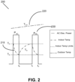
- FIG. 2 illustrates a typical air conditioning operation.
- An air conditioning (AC) system 200 operates to maintain the indoor temperature 210 of a home, office or other indoor structure, between a desired temperature range, e.g., as set by a user.
- the temperature range is illustrated in FIG. 2 as being between an upper limit T hi and a lower limit T lo .
- the temperature limits T hi and T lo are static and may not be breached by the indoor temperature 210.
- the system 200 may automatically switch on the air conditioner to decrease the indoor temperature 210 so as not to exceed the upper limit T hi .
- the system 200 may switch off the air conditioner so that the temperature 210 does not drop below the lower limit T lo .
- the outside temperature is illustrated at T out 220, and in this example is rising linearly over time periods t 0 , t 1 and t 2 .
- the power consumption profile is illustrated by profile 230, and shows that power consumption increases when the AC is turned on when the temperature 210 reaches the upper limit T hi .
- the indoor temperature 210 drops over a period of time to the lower limit T lo .
- the temperature 210 is at the lower limit T lo , at time t 0 , the AC is turned off and, due to the outside temperature T out 220 steadily increasing and higher than the indoor temperature 210, the indoor temperature 210 starts increasing when the AC is turned off and, at time t 1 , the indoor temperature 210 reaches the upper limit T hi once again.
- the AC in order to maintain an indoor temperature that is below maximum comfort threshold in the time window t 0 to t 2 , or below the upper temperature limit represented by the upper limit T hi illustrated in FIG. 2 , the AC is turned on for a given period of time that is shorter than the time window t 0 to t 2 .
- the AC on-duration time may change depending on the time at which the AC is being turned on within the given time window t 0 to t 2 due to the fact that the outdoor temperature 220 continues to rise over time and indoor temperature 210 may have different values based on the start time of the AC .
- the on-duration time variation may be determined by the way in which the indoor room temperature 210 dynamically changes over time, e.g., based on the outdoor temperature 220 and the physical characteristics of the indoor structure.
- Principles of this disclosure provide a model-based approach to determine the dynamic behavior of indoor room temperature 210 over time. Based on this determination, an estimated AC on-duration may be determined as a function of the on-time delay and a forecast of the outdoor temperature 220. In addition, based on the determination of the dynamic behavior of indoor room temperature 210 over time, an estimated start time and end time of every DER in the indoor structure may be determined, while keeping the total power consumption below the requested amount during the time window t 0 to t 2 .
- FIG. 3 is a diagram representing an indoor structure, in accordance with various principles of the present disclosure.
- the dynamic indoor temperature T in may be modeled as a function of the AC power P AC , the outdoor temperature T out , and the home thermal parameters expressed by the thermal resistance R th and the thermal capacitance C th . This is shown by the RC-circuit diagram in FIG. 3 below and the dynamical equation is in Equation (1) below.
- T ⁇ in T out ⁇ T in R th C th ⁇ P AC C th
- T in is the indoor temperature
- T out is the outdoor temperature
- R th is thermal resistance
- C th is thermal capacitance.
- the thermal parameters R th and C th of the indoor structure may depend on the materials, insulation, and other physical characteristics of the indoor structure. Among these parameters, the thermal resistance R th may represent the thermal loss in the indoor structure, and the thermal capacitance C th may represent the thermal energy hosting capacity of the indoor structure. In an example, the thermal resistance R th and the thermal capacitance C th may be calibrated using, e.g., historical measurements of indoor temperature, outdoor temperature and DER consumption power in the indoor structure.
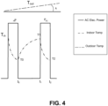
- FIG. 4 illustrates an air conditioning temperature profile, in accordance with various principles of the present disclosure.
- the indoor temperature T in may be below a maximum temperature threshold, at which point the DER such as, e.g., the AC unit, may switch off.
- the indoor temperature may increase from a temperature T 0 to T 1 between times t 0 and t 1 .
- the temperature may decrease to T 0 .
- the AC may be turned off again, and the indoor temperature may rise up to T 1 between times t 0 and t 1 .
- the AC may be turned on again, and the indoor temperature may decrease back to T 2 between times t 1 and t 2 .
- the upper temperature limit T1 in this example is a dynamic temperature limit and may vary over time based on, e.g., the power consumptions of other DERs within the same indoor structure.
- Equation (2) below derived from Equation (1) above when consumption P AC equals zero, may be used to calculate the product of R th and C th .
- R th C th ⁇ t 0 t 1 T out ⁇ T in dt T 1 ⁇ T 0
- C th ⁇ t 1 t 2 P AC dt T 1 ⁇ T 2 + 1 R th C th ⁇ t 1 t 2 T out ⁇ T in dt
- the estimated thermal-resistance R th and thermal-capacitance C th govern the home indoor temperature variations across time based on the outdoor temperature and AC power P AC , as described in Equation (1).
- FIGS. 5A-5C illustrate AC power consumption and temperature profiles, in accordance with various principles of the present disclosure.
- FIG. 5A illustrates the power consumption profile P AC over time, where power increases rapidly to P AC during operation of the AC starting at time t ON and during duration t min , and then decreases rapidly to zero at time torr + t min when the AC is turned off.
- t min is the minimum amount of time necessary to activate the AC in order to reach a desired temperature while keeping the power consumption at or below a required power consumption limit.
- FIG. 5B is a plot of the indoor temperature over time, which varies between a high temperature of T 1 and a low temperature of T 2 .
- FIG. 5A the temperature decreases when the AC is turned on at t ON and increases again when the AC is turned off at torr + t min .
- FIG. 5C is a plot of the outdoor temperature over time.
- the outdoor temperature is linearly dependent of time.
- the outdoor temperature is uncorrelated to whether the AC of the indoor structure is turned on or off.
- FIGS. 5B and 5C illustrate two time and temperature coordinates that formulate a problem with two equations and two unknowns.
- the first coordinate is the time t ON and indoor temperature T 1 when the AC is turned on.
- the second coordinate is the time t ON + t min and indoor-temperature T 2 when the AC is turned off.
- the indoor temperature reaches the known maximum indoor temperature threshold T max at the end of a desired time duration t DR after the AC is turned off.
- Outdoor temperature measurements T out1 and T out2 at times t ON and t ON + t min are used to estimate a linear outdoor temperature variation having a slope k.
- Equation (5) may be used to solve the AC minimum on-duration t min that avoids having the indoor temperature exceed the maximum indoor temperature threshold T max at the end of a desired time duration t DR when the AC is delayed by t ON .
- T max T out 2 ⁇ kR th C th + k t DR ⁇ t ON + t min + kR th C th + T out 1 ⁇ kR th C th ⁇ R th P AC + kt min + kR th C th + R th P AC + T 1 ⁇ T out 1 ⁇ e ⁇ t min R th C th ⁇ T out 2 ⁇ e ⁇ t DR ⁇ t ON + t min R th c th
- FIG. 5C illustrates a case where the outdoor temperature varies linearly.
- the outdoor temperature may be constant over time.
- the calculated t min and torr may be different than when the outdoor temperature varies linearly over time.
- the above calculations allow the determination of the minimum amount of time t min , and the time to turn on the DER torr, for any DER in order to achieve at least two objectives: i) keep the indoor temperature within an acceptable range of a desired temperature, and ii) remain below the required maximum allowed power consumption.
- the same calculation may be performed for each one of the DERs located in an indoor structure, and referring back to FIG. 1 , the above calculations may be performed not only for the DER 120A (AC unit), but for each of the other DERs such as, e.g., 120B, 120C and 120D, and any other DER present in the indoor structure 110.
- FIG. 6A is a flow chart illustrating a method of managing a distributed energy resource (DER) within an indoor structure or a group of indoor structures within a same utility network, in accordance with various principles of the present disclosure.
- DER distributed energy resource
- FIG. 6A the method 600 includes operation 610, where a time window and a power consumption limit for the DER, e.g., an AC unit, are received.
- the time window may correspond to a demand-response (DR) event which may be, e.g., a peak consumption event in the life of the indoor structure, or in the life of other indoor structures or households connected to the same utility network.
- DR demand-response
- the DR event may be early in the morning or late in the afternoon when activity in the home is at its highest, e.g., when members of the household ready themselves to go to work or school, or when they come back home from work or school.
- the power consumption limit may be received by a utility provider, and may be applicable during the received time window.
- the power consumption limit may be a limit beyond which higher rates may be applicable to each additional unit of power such as, e.g., each additional kWh. Accordingly, it may be advantageous to maintain the power consumption below the power consumption limit.
- the next operation in method 600 may be operation 620 further discussed below.
- the outdoor temperature e.g., the temperature outside the indoor structure(s) is measured.
- the outdoor temperature is measured at a given point in time within the time window.
- the outside temperature may be constant during the time window.
- the outside temperature may vary over time during the time window.
- the indoor temperature may be determined.
- the indoor temperature may be determined as described in Equation (4) above based on the measured outdoor temperature, the estimated thermal-resistance of the indoor structure, the estimated thermal-capacitance of the indoor structure, the start time of operation of the DER, the received power consumption limit, and the slope of the variation of the outdoor temperature over time.
- the indoor temperature model parameters such as, e.g., R th and C th , ma be calibrated.
- the minimum time of operation of the DER is determined.
- the minimum time of operation of the DER is determined so that the power consumption of the DER is equal to or below the received power consumption limit.
- the minimum time of operation of the DER may be determined as described in Equation (6) above based on the outdoor temperature at a beginning of operation of the DER, the outdoor temperature at an end of operation of the DER, the end time of the received time window, the time of operation of the DER, the received power consumption limit, the slope of variation of the outdoor temperature over time, the start time of operation of the DER, the estimated thermal-resistance of the indoor structure, the estimated thermal-capacitance of the indoor structure, the measured outdoor temperature, and the indoor temperature at the time of operation of the DER.
- the start time and the end time of operation of the DER may be determined.
- FIG. 6B is a flow chart illustrating a method of managing a plurality of distributed energy resources (DERs) within an indoor structure, in accordance with various principles of the present disclosure.
- method 605 is described through use of at least the example system 700 described in combination with the systems discussed above. However, it is appreciated that the method 605 may be performed by any suitable system.
- the method 605 includes operation 615, where a time window and a power consumption limit for the totality of the DERs located in an indoor structure(s), e.g., the combination of an AC unit, a car charger, a water heater, and the like, are received.
- the time window may correspond to a demand-response (DR) or grid event, as discussed above.
- DR demand-response
- the power consumption limit is received by a utility provider, may be applicable during the received time window, and concerns the total consumption of all the DERs, e.g., appliances, located in the indoor structure or household.
- the start time and end time of operation of a first DER of the plurality of DERs during the received time window is determined. For example, the start and end times may be determined as discussed above with respect to operation 650.
- the combined power consumption of all the DERs located in the indoor structure and that are turned on during the received time window is calculated. For example, the combined power consumption of all the DERs may be determined by summing up the power consumption of each DER that is turned on during the received time window.
- the determined combined power consumption is compared to the received power consumption limit.
- the start time, the end time, or both the start time and the end time of operation of the first DER is changed.
- the start time of operation of the first DER may be delayed, or the end time of operation of the first DER may be moved up, or both the start time and the end time of operation of the first DER may be varied.
- the method 605 returns to operation 645 during which the combined power consumption is measured anew, and the method 605 continues to operations 655, 665 and/or 675.
- the method 605 determines, and varies when needed, the start times and end times of each of the DERs located in the indoor structure(s) in order to ensure that the combined power consumption of all the DERs remains equal to or lower than the power consumption limit that was received during operation 625.
- FIG. 7 depicts a block diagram of a computing device, according to various principles of the present disclosure.
- the computing device 700 may include a bus 702 or other communication mechanism of similar function for communicating information, and at least one processing element 704 (collectively referred to as processing element 704) coupled with bus 702 for processing information.
- processing element 704 may include a plurality of processing elements or cores, which may be packaged as a single processor or in a distributed arrangement.
- a plurality of virtual processing elements 704 may be included in the computing device 700 to provide the control or management operations for the system 100 and methods 600 and 605 illustrated above.
- the computing device 700 may also include one or more volatile memory(ies) 706, which can for example include random access memory(ies) (RAM) or other dynamic memory component(s), coupled to one or more busses 702 for use by the at least one processing element 704.
- Computing device 700 may further include static, non-volatile memory(ies) 708, such as read only memory (ROM) or other static memory components, coupled to busses 702 for storing information and instructions for use by the at least one processing element 704.
- a storage component 710 such as a storage disk or storage memory, may be provided for storing information and instructions for use by the at least one processing element 704.
- the computing device 700 may include a distributed storage component 712, such as a networked disk or other storage resource available to the computing device 700.
- the computing device 700 may be coupled to one or more displays 714 for displaying information to a user.
- the computing device 700 may further include an input/output (I/O) component, such as a serial connection, digital connection, network connection, or other input/output component for allowing intercommunication with other computing components and the various components of the system 100 and methods 600 and 605 illustrated above.
- I/O input/output
- computing device 700 can be connected to one or more other computer systems via a network to form a networked system.
- networks can for example include one or more private networks or public networks, such as the Internet.
- one or more computer systems can store and serve the data to other computer systems.
- the one or more computer systems that store and serve the data can be referred to as servers or the cloud in a cloud computing scenario.
- the one or more computer systems can include one or more web servers, for example.
- the other computer systems that send and receive data to and from the servers or the cloud can be referred to as client or cloud devices, for example.
- Various operations of the system 100 and methods 600 and 605 illustrated above may be supported by operation of the distributed computing systems.
- the computing device 700 may be operative to control operation of the components of the system 100 and methods 600 and 605 illustrated above through a communication device such as, e.g., communication device 720, and to handle data provided from the data sources as discussed above with respect to the system 100 and methods 600 and 605.
- analysis results are provided by the computing device 700 in response to the at least one processing element 704 executing instructions contained in memory 706 or 708 and performing operations on the received data items. Execution of instructions contained in memory 706 and/or 708 by the at least one processing element 704 can render the system 100 and methods 600 and 605 operative to perform methods described herein.
- Non-volatile media includes, for example, optical or magnetic disks, such as disk storage 710.
- Volatile media includes dynamic memory, such as memory 706.
- Transmission media includes coaxial cables, copper wire, and fiber optics, including the wires that include bus 702.
- Computer-readable media or computer program products include, for example, a floppy disk, a flexible disk, hard disk, magnetic tape, or any other magnetic medium, a CD-ROM, digital video disc (DVD), a Blu-ray Disc, any other optical medium, a thumb drive, a memory card, a RAM, PROM, and EPROM, a FLASH-EPROM, any other memory chip or cartridge, or any other tangible medium from which a computer can read.
- Various forms of computer readable media may be involved in carrying one or more sequences of one or more instructions to the processing element 704 for execution.
- the instructions may initially be carried on the magnetic disk of a remote computer.
- the remote computer can load the instructions into its dynamic memory and send the instructions over a telephone line using a modem.
- a modem local to computing device 700 can receive the data on the telephone line and use an infra-red transmitter to convert the data to an infra-red signal.
- An infra-red detector coupled to bus 702 can receive the data carried in the infra-red signal and place the data on bus 702.
- Bus 702 carries the data to memory 706, from which the processing element 704 retrieves and executes the instructions.
- the instructions received by memory 706 and/or memory 708 may optionally be stored on storage device 710 either before or after execution by the processing element 704.
- instructions operative to be executed by a processing element to perform a method are stored on a computer-readable medium.
- the computer-readable medium can be a device that stores digital information.
- a computer-readable medium includes a compact disc read-only memory (CD-ROM) as is known in the art for storing software.
- CD-ROM compact disc read-only memory
- the computer-readable medium is accessed by a processor suitable for executing instructions configured to be executed.
- a method of managing a distributed energy resource (DER) within an indoor structure comprising receiving a time window; receiving a power consumption limit; measuring an outdoor temperature; determining an indoor temperature of the indoor structure based at least on the measured outdoor temperature, the received power consumption limit, and the received time window; determining a minimum time of operation of the DER so that a power consumption of the DER is equal to or below the received power consumption limit without compromising a quality of service controlled by the DER.
- DER distributed energy resource
- Aspect 2 The method of aspect 1, wherein the power consumption limit is applicable during the received time window.
- determining the indoor temperature comprises determining the indoor temperature via Equation (4):
- T in t T out t 0 ⁇ kR th C th ⁇ R th P AC + kt + kR th C th + R th P AC + T in t 0 ⁇ T out t 0 ⁇ e ⁇ t R th C th T out is the measured outdoor temperature;
- R th is an estimated thermal-resistance of the indoor structure;
- C th is an estimated thermal-capacitance of the indoor structure;
- t 0 is a start time of operation of the DER;
- P AC is the received power consumption limit; and
- k is a slope of variation of the outdoor temperature over time.
- a method of managing a plurality of distributed energy resources (DERs) within an indoor structure comprising receiving a time window; receiving a power consumption limit; determining a combined power consumption of the plurality of DERs in operation during the received time window; and for each DER and during the received time window, determining a start time of operation thereof and an end time of operation thereof so that the determined combined power consumption is equal to or lower than the received power consumption limit without compromising a quality of service controlled by individual DER.
- DERs distributed energy resources
- Aspect 7 The method of aspect 6, wherein measuring the combined power consumption of the plurality of DERs in operation during the received time window comprises calculating a sum of the power consumptions of each DER that is in operation during the received time window.
- Aspect 8 The method of aspect 6, wherein when the measured combined power consumption of the DERs in operation during the received time window is greater than the received power consumption limit, the method further comprises changing one of the start time and the end time of at least one of the DERs so that the measured combined power consumption of the DERs in operation during the received time window is equal to or lower than the received power consumption limit without compromising a quality of service controlled by the DER.
- Aspect 9 The method of aspect 8, wherein changing one of the start time and the end time of a DER comprises changing one of the start time and the end time of the DER so as to reduce an overlap of the power consumption thereof with a power consumption of another DER during the time window without compromising a quality of service controlled by the DER.
- Aspect 10 The method of aspect 9, wherein changing one of the start time and the end time of the DER so as to reduce the overlap of the power consumption thereof with a power consumption of another DER during the time window results in a lower combined power consumption without compromising a quality of service controlled by the DER.
- a system for managing a distributed energy resource (DER) within an indoor structure comprising: a data receiver; an updatable data repository functionally coupled to the data receiver; a display device functionally coupled to the data receiver; a processor operatively coupled to the data receiver, to the updatable data repository and to the display device; and a memory coupled to the processor, the memory storing instructions that, when executed by the processor, perform a set of operations comprising: receiving, at the data receiver, a time window; receiving, at the data receiver, a power consumption limit; measuring an outdoor temperature; determining, via the processor, an indoor temperature of the indoor structure based at least on the measured outdoor temperature, the received power consumption limit, and the received time window; determining, via the processor, a minimum time of operation of the DER so that a power consumption of the DER is equal to or below the received power consumption limit without compromising a quality of service controlled by the DER.
- a distributed energy resource DER
- Aspect 12 The system of aspect 11, wherein the DER comprises one of an AC unit, a water heater, an electric vehicle charger, and a solar panel.
- a system for managing a plurality of distributed energy resources (DERs) within an indoor structure comprising: a data receiver; an updatable data repository functionally coupled to the data receiver; a display device functionally coupled to the data receiver; a processor operatively coupled to the data receiver, to the updatable data repository and to the display device; and a memory coupled to the processor, the memory storing instructions that, when executed by the processor, perform a set of operations comprising: receiving, at the data receiver, a time window; receiving, at the data receiver, a power consumption limit; determining, via the processor, a combined power consumption of the plurality of DERs in operation during the received time window; and for each DER and during the received time window, determining, via the processor, a start time of operation thereof and an end time of operation thereof so that the determined combined power consumption is equal to or lower than the received power consumption limit without compromising a quality of service controlled by the DER.
- DERs distributed energy resources
- Aspect 14 The system of aspect 13, wherein the DERs comprise at least one of an AC unit, a water heater, an electric vehicle charger, and a solar panel.
- Aspect 15 The system of aspect 13, wherein the combined power consumption of DERs in operation during the received time window is determined by calculating a sum of the power consumptions of each DER that is in operation during the received time window.
- Aspect 16 The system of aspect 13, wherein when the measured combined power consumption of the plurality of DERs in operation during the received time window is greater than the received power consumption limit, the system changes one of the start time and the end time of at least one of the DERs so that the determined combined power consumption of the plurality of DERs in operation during the received time window is equal to or less than the received power consumption limit without compromising a quality of service controlled by the DER.
Landscapes
- Engineering & Computer Science (AREA)
- Chemical & Material Sciences (AREA)
- Combustion & Propulsion (AREA)
- Mechanical Engineering (AREA)
- General Engineering & Computer Science (AREA)
- Signal Processing (AREA)
- Power Engineering (AREA)
- Human Computer Interaction (AREA)
- Physics & Mathematics (AREA)
- Fuzzy Systems (AREA)
- Mathematical Physics (AREA)
- Air Conditioning Control Device (AREA)
- Supply And Distribution Of Alternating Current (AREA)
Abstract
A system and method for managing a distributed energy resource (DER) within an indoor structure, the method including receiving a time window, receiving a power consumption limit, measuring an outdoor temperature, determining an indoor temperature of the indoor structure based at least on the measured outdoor temperature, the received power consumption limit, and the received time window, determining a minimum time of operation of the DER so that a power consumption of the DER is equal to or below the received power consumption limit during the received time window without compromising the quality of service controlled by the DER.
Description
- Managing energy consuming appliances, also referred to as distributed energy resources (DERs), typically necessitates a local behind-the-meter controller to manage local DERs in a residential household. Air conditioning is a member of a family of systems and techniques that provide heating, ventilation, and air conditioning (HVAC) that are typically present in a home and that consume energy, particularly during peak usage times, especially when household members are at home.
- In managing DERs, a controller typically allocates turning on and off schedules for local DERs to avoid exceeding a maximum power threshold during grid events such as, e.g., frequency regulation, voltage regulation, a Demand-Response (DR) event, while maintaining DERs Quality-of-Services and minimizing energy cost. Flexible load solutions for various grid services including frequency regulation and peak shaving are advantageous for power or electric utilities. To achieve this flexibility, utilities typically utilize a physical controller at home level to manage the operations of the distributed-energy-resources (DERs) such as the air-conditioner, electric water heater, electric vehicles, solar plus battery storage, and the like.
- In one aspect, the technology relates to a method of managing a distributed energy resource (DER) within an indoor structure, the method including receiving a time window, receiving a power consumption limit, measuring an outdoor temperature, determining an indoor temperature of the indoor structure based at least on the measured outdoor temperature, the received power consumption limit, and the received time window, determining a minimum time of operation of the DER so that a power consumption of the DER is equal to or below the received power consumption limit during the received time window without compromising the quality of service controlled by the DER.
- In an example of the above aspect, the power consumption limit is applicable during the received time window. In another example, determining the indoor temperature as a function of time is described by Equation (4) below, wherein Tout is the measured outdoor temperature, Rth is an estimated thermal-resistance of the indoor structure, Cth is an estimated thermal-capacitance of the indoor structure, t0 is a start time of operation of the DER, PAC is the received power consumption limit, and k is a slope of variation of the outdoor temperature over time. In another example, determining the minimum time of operation of the DER with the assumption of linear outdoor temperature variation includes determining the minimum of time tmin based on Equation (5), wherein Tmax is the maximum indoor temperature, Tout2 is the outdoor temperature at an end of operation of the DER, tDR is an end time of the received time window, torr is an arbitrary start-time of operation of the DER, T1 is an indoor temperature at time tON and Tout1 is the outdoor temperature at a beginning of operation of the DER. In yet another example, determining the minimum time of operation of the DER with the assumption of constant outdoor temperature includes determining the minimum of time tmin based on Equation (6).
- In another aspect, the technology relates to a method of managing a plurality of distributed energy resources (DERs) within an indoor structure, the method including receiving a time window, receiving a power consumption limit, measuring a combined power consumption of DERs in operation during the received time window, and for each DER and during the received time window, determining a start time of operation and an end time of operation thereof so that the determined combined power consumption is equal to or lower than the received power consumption limit without compromising the quality of service controlled by individual DER.
- In an example of the above aspect, measuring a combined power consumption of DERs in operation during the received time window includes calculating a sum of the power consumptions of each DER that is in operation during the received time window. In another example, when the measured combined power consumption of the DERs in operation during the received time window is greater than the received power consumption limit, the method further includes changing one of the start time and the end time of at least one of the DERs so that the measured combined power consumption of the DERs in operation during the received time window is equal to or less than the received power consumption limit without compromising the quality of service controlled by individual DER.
- In another example of the above aspect, changing one of the start time and the end time of a DER includes changing one of the start time and the end time of the DER so as to reduce an overlap of the power consumption thereof with a power consumption of another DER during the time window. In yet another example, changing one of the start time and the end time of the DER so as to reduce the overlap of the power consumption thereof with a power consumption of another DER during the time window results in a lower combined power consumption without compromising the quality of service controlled by individual DER.
- In yet another aspect, the technology relates to a system for managing a distributed energy resource (DER) within an indoor structure, the system including a data receiver, an updatable data repository functionally coupled to the data receiver, a display device functionally coupled to the data receiver, a processor operatively coupled to the data receiver, to the updatable data repository and to the display device, and a memory coupled to the processor. In an example of the above aspect, the memory stores instructions that, when executed by the processor, perform a set of operations including receiving, at the data receiver, a time window, receiving, at the data receiver, a power consumption limit, measuring, via the processor, an outdoor temperature, determining, via the processor, an indoor temperature of the indoor structure based at least on the measured outdoor temperature, the received power consumption limit, and the received time window, determining, via the processor, a minimum time of operation of the DER so that a power consumption of the DER is equal to or below the received power consumption limit during the received time window without compromising the quality of service controlled by individual DER. In an example of the above aspect, the DER includes one of an AC unit, a water heater, an electric vehicle charger, and a solar panel.
- In a further aspect, the technology relates to a system for managing a plurality of distributed energy resources (DERs) within an indoor structure, the system including a data receiver, an updatable data repository functionally coupled to the data receiver, a display device functionally coupled to the data receiver, a processor operatively coupled to the data receiver, to the updatable data repository and to the display device, and a memory coupled to the processor. In an example of the above aspect, the memory stores instructions that, when executed by the processor, perform a set of operations including receiving, at the data receiver, a time window, receiving, at the data receiver, a power consumption limit, measuring, via the processor, a combined power consumption of DERs in operation during the received time window, and for each DER and during the received time window, determining, via the processor, a start time of operation and an end time of operation thereof so that the determined combined power consumption is equal to or lower than the received power consumption limit without compromising the quality of service controlled by individual DER.
- In another example of the above aspect, the DERs include at least one of an AC unit, a water heater, an electric vehicle charger, and a solar panel. In yet another example, the system measures the combined power consumption of DERs in operation during the received time window by calculating a sum of the power consumptions of each DER that is in operation during the received time window. In a further example, when the measured combined power consumption of the DERs in operation during the received time window is greater than the received power consumption limit, the system changes one of the start time and the end time of at least one of the DERs so that the measured combined power consumption of the DERs in operation during the received time window is equal to or less than the received power consumption limit without compromising the quality of service controlled by individual DER.
- The accompanying drawings, which are incorporated in and constitute a part of the description, illustrate several principles of the present disclosure. A brief description of the drawings is as follows:
-
FIG. 1 is an overview of a control system for controlling a plurality of DERs in an indoor structure, in accordance with various principles of the present disclosure. -
FIG. 2 is a diagram illustrating an air conditioning (AC) operation. -
FIG. 3 is a diagram representing air conditioning parameters for a structure, in accordance with various principles of the present disclosure. -
FIG. 4 illustrates an air conditioning temperature profile, in accordance with various principles of the present disclosure. -
FIGS. 5A-5C illustrate AC power consumption and temperature profiles, in accordance with various principles of the present disclosure. -
FIG. 6A is a flow chart illustrating a method of managing a distributed energy resource (DER) within an indoor structure, in accordance with various principles of the present disclosure. -
FIG. 6B is a flow chart illustrating a method of managing a plurality of distributed energy resources (DERs) within an indoor structure, in accordance with various principles of the present disclosure. -
FIG. 7 depicts a block diagram of a computing device. - Decentralized distributed energy resources (DERs) management typically necessitates a local behind-the-meter controller to manage local DERs. The controller allocates turning on and off schedules for local DERs to avoid exceeding a maximum power threshold during a Demand-Response (DR) event, while maintaining DERs Quality-of-Services and minimizing energy cost. Examples of the present disclosure allow to determine a minimum on-duration of a DER such as, e.g., an AC unit, in an indoor structure in order to maintain the indoor temperature to be within the user-defined maximum and minimum temperature thresholds during the DR event. For example, such determination may be based on a calibrated RC-model.
- Examples of the present disclosure include a system such as, e.g., a smart meter, that is capable of scheduling the start times and end times of multiple DERs in an indoor structure such as, e.g., a household, in order to provide a desired load flexibility for utility grid services. Examples include a system configured to control the AC system while keeping the indoor temperature of the home within a desired temperature range. In addition, the scheduling of the AC may be performed in coordination with other DERs to maximize grid flexibility by minimizing the net home load consumption while considering comfort bound constraints for all DERs. For example, the controller may turn on and off the AC at various times to avoid exceeding the net home power threshold during a Demand-Response (DR) event while maintaining the indoor temperature limits set by the customer.
- Traditional demand response (DR) programs typically attempt to centrally control AC units from multiple households by aggregating control centrally, and consequently have difficulty considering individualized feedback from each household based on that household's specific usage patterns. Accordingly, there is a technical problem in that the indoor temperature of an indoor structure may not always be able to be maintained within a desired temperature comfort range for each household. A technical solution to this problem includes controlling, at the household level, the consumption of each DER or appliance located therein, so that the combined power consumption of all the DERs within the DR event does not exceed a power consumption limit. For example, the power consumption limit may be provided by the utility company.
-
FIG. 1 is an overview of a control system for controlling a plurality of DERs in an indoor structure, in accordance with various principles of the present disclosure. InFIG. 1 , thepower control system 100 includes a typical home orstructure 110 that has a plurality of appliances, referred to herein as DERs, 120A, 120B, 120C and 120D, that may be typically present in a household. In various examples, operation of the DERs 120A-120D may take place during a gridservice event window 130, also referred to as a DR event or time window, and in order to achieve desired power savings during thetime window 130, each DER 120A-120D may be turned on and off at different times and for different durations. For example, the desired power savings may be achieved when the totality of power consumption equal to or lower than a requestedpower 140 that may be provided, e.g., by the power utility company. Accordingly, the requestedpower 140 is a power consumption limit. - In the example illustration of
FIG. 1 , DER 120A corresponds to a compressor for an AC unit, and itspower consumption profile 150A shows a given power consumption that is constant and that extends over a first period oftime 160A. Also, DER 120B corresponds to a water heater, and itspower consumption profile 150B also shows a given power consumption that is constant and that extends over a second period oftime 160B. As an example, thepower consumption profile 150B shows that power consumption starts after the power consumption of DER 120A has ended, as illustrated in the x-axis that describes time. For example, periods oftime power consumption profile 150C of the EV battery extends over a period oftime 160C and remains constant over that period oftime 160C. In this example, thepower consumption profile 150C shows that power consumption of the EV battery starts after the power consumption of the AC compressors ends and before the power consumption of the water heater starts. For example, the period oftime 160C does not overlap the periods oftime power consumption profile 150D extends over a period oftime 160D, and the period oftime 160D overlaps the period oftime 160B during which theDER 120B is turned on. Accordingly, in this example,DERs 120B and 120D are turned on at substantially the same time. In various examples, although the power consumption profiles 150A-150D are shown to have little overlap, the various power consumption profiles 150A-150D for DERs 120A-120D, or for any other DERs not illustrated inFIG. 1 , may overlap each other in terms of their start times and end times. In various examples, thesystem 100 operates as desired when the combination of all the power consumption profiles 150A-150D in operation during the gridservice event window 140 remain under the requestedpower 140. For example, the combination of all the power consumption profiles 150A-150D may be determined as the sum of the power consumptions of each of the DERs at each time during thetime window 130. - In various examples, the
AC control system 100 is configured to schedule multiple DERs (air conditioner, electric water heater, electric vehicle, and the like) inside a household, office or other indoor structure, to minimize the net home power consumption, while at the same time keep the total power consumption for all DERs under a required power consumption limit. For example, minimizing the net home power consumption may mean maintaining the total power consumption of all the DERs within the indoor structure under the requestedpower 140. In the example of the AC compressor 120A, thepower control system 100 may delay, or accelerate, the turning on of the AC in order to control the net power consumption of the DERs in the indoor structure. For example, if the AC compressor 120A and the EV battery 120C charging took place simultaneously, the net power threshold may be violated, i.e., the total power consumption may become greater than therequest power 140. In this case, the AC compressor 120A may be turned off for a desired length of time in order to accommodate charging of the EV battery 120C and without violating the maximum power bound set for net household power consumption which is the requestedpower 140. For example, the start of operation of the AC compressor 120A may be delayed to after the operation of the EV battery 120C, or moved up to be before the operation of the EV battery 120C. -
FIG. 2 illustrates a typical air conditioning operation. An air conditioning (AC)system 200 operates to maintain theindoor temperature 210 of a home, office or other indoor structure, between a desired temperature range, e.g., as set by a user. The temperature range is illustrated inFIG. 2 as being between an upper limit Thi and a lower limit Tlo. In this example, the temperature limits Thi and Tlo are static and may not be breached by theindoor temperature 210. When theindoor temperature 210 reaches or approaches the upper limit Thi, thesystem 200 may automatically switch on the air conditioner to decrease theindoor temperature 210 so as not to exceed the upper limit Thi. On the other hand, when theindoor temperature 210 reaches or approaches the lower limit Tlo, thesystem 200 may switch off the air conditioner so that thetemperature 210 does not drop below the lower limit Tlo. InFIG. 2 , the outside temperature is illustrated atT out 220, and in this example is rising linearly over time periods t0, t1 and t2. - In
FIG. 2 , the power consumption profile is illustrated byprofile 230, and shows that power consumption increases when the AC is turned on when thetemperature 210 reaches the upper limit Thi. As a result of the AC being turned on, and the power consumption being at PAC, theindoor temperature 210 drops over a period of time to the lower limit Tlo. When thetemperature 210 is at the lower limit Tlo, at time t0, the AC is turned off and, due to theoutside temperature T out 220 steadily increasing and higher than theindoor temperature 210, theindoor temperature 210 starts increasing when the AC is turned off and, at time t1, theindoor temperature 210 reaches the upper limit Thi once again. During the period of time between t0 and t1, power consumption of the AC system is close to, or equal to, zero because the AC is turned off. At time t1, because theindoor temperature 210 has reached the upper limit Thi, the AC is turned on again, the power consumption increases to PAC, theindoor temperature 210 starts decreasing until reaching the lower limit Tlo at time t2. The above describes a typical indoor temperature control cycle. - In various examples, in order to maintain an indoor temperature that is below maximum comfort threshold in the time window t0 to t2, or below the upper temperature limit represented by the upper limit Thi illustrated in
FIG. 2 , the AC is turned on for a given period of time that is shorter than the time window t0 to t2. In an example, the AC on-duration time may change depending on the time at which the AC is being turned on within the given time window t0 to t2 due to the fact that theoutdoor temperature 220 continues to rise over time andindoor temperature 210 may have different values based on the start time of the AC . The on-duration time variation may be determined by the way in which theindoor room temperature 210 dynamically changes over time, e.g., based on theoutdoor temperature 220 and the physical characteristics of the indoor structure. - Principles of this disclosure provide a model-based approach to determine the dynamic behavior of
indoor room temperature 210 over time. Based on this determination, an estimated AC on-duration may be determined as a function of the on-time delay and a forecast of theoutdoor temperature 220. In addition, based on the determination of the dynamic behavior ofindoor room temperature 210 over time, an estimated start time and end time of every DER in the indoor structure may be determined, while keeping the total power consumption below the requested amount during the time window t0 to t2. -
FIG. 3 is a diagram representing an indoor structure, in accordance with various principles of the present disclosure. For example, the dynamic indoor temperature Tin may be modeled as a function of the AC power PAC, the outdoor temperature Tout, and the home thermal parameters expressed by the thermal resistance Rth and the thermal capacitance Cth. This is shown by the RC-circuit diagram inFIG. 3 below and the dynamical equation is in Equation (1) below.

- In
FIG. 3 , Tin is the indoor temperature, Tout is the outdoor temperature, Rth is thermal resistance, Cth is thermal capacitance. In various examples, the thermal parameters Rth and Cth of the indoor structure may depend on the materials, insulation, and other physical characteristics of the indoor structure. Among these parameters, the thermal resistance Rth may represent the thermal loss in the indoor structure, and the thermal capacitance Cth may represent the thermal energy hosting capacity of the indoor structure. In an example, the thermal resistance Rth and the thermal capacitance Cth may be calibrated using, e.g., historical measurements of indoor temperature, outdoor temperature and DER consumption power in the indoor structure. -
FIG. 4 illustrates an air conditioning temperature profile, in accordance with various principles of the present disclosure. InFIG. 4 , the indoor temperature Tin may be below a maximum temperature threshold, at which point the DER such as, e.g., the AC unit, may switch off. For example, due to a high outdoor temperature Tout, the indoor temperature may increase from a temperature T0 to T1 between times t0 and t1. For example, when the indoor temperature Tin reaches the maximum temperature threshold and the AC switches on, the temperature may decrease to T0. When the temperature reaches T0, then the AC may be turned off again, and the indoor temperature may rise up to T1 between times t0 and t1. When the indoor temperature reaches T1, the AC may be turned on again, and the indoor temperature may decrease back to T2 between times t1 and t2. In an example, although the temperature profile described inFIG. 4 appears to be similar to the temperature profile described inFIG. 2 , a difference is that the upper temperature limit T1 in this example is a dynamic temperature limit and may vary over time based on, e.g., the power consumptions of other DERs within the same indoor structure. - Referring to
FIGS. 3 and4 , Equation (2) below, derived from Equation (1) above when consumption PAC equals zero, may be used to calculate the product of Rth and Cth.

- Using RthCth thus calculated, Cth may be derived using Equation (3) below:

- In various examples, the estimated thermal-resistance Rth and thermal-capacitance Cth govern the home indoor temperature variations across time based on the outdoor temperature and AC power PAC, as described in Equation (1). For example, using Laplace's mathematical transformations, the indoor temperature dynamics in the time domain may be derived as shown in Equation (4) below:

- Accordingly, knowing Rth, Cth, Tout, PAC, and experimental factor k representing a slope of the outdoor temperature variation over time as illustrated in
FIG. 4 , it becomes possible to dynamically determine the indoor temperature Tin at any point in time t. Based on the determined dynamic indoor temperature Tin, it becomes possible to calculate the minimum on-duration time tmin of the AC, as further discussed below. -
FIGS. 5A-5C illustrate AC power consumption and temperature profiles, in accordance with various principles of the present disclosure.FIG. 5A illustrates the power consumption profile PAC over time, where power increases rapidly to PAC during operation of the AC starting at time tON and during duration tmin, and then decreases rapidly to zero at time torr + tmin when the AC is turned off. In this case, tmin is the minimum amount of time necessary to activate the AC in order to reach a desired temperature while keeping the power consumption at or below a required power consumption limit.FIG. 5B is a plot of the indoor temperature over time, which varies between a high temperature of T1 and a low temperature of T2. When correlated toFig. 5A , the temperature decreases when the AC is turned on at tON and increases again when the AC is turned off at torr + tmin.FIG. 5C is a plot of the outdoor temperature over time. In this case, the outdoor temperature is linearly dependent of time. For example, the outdoor temperature is uncorrelated to whether the AC of the indoor structure is turned on or off. - Accordingly,
FIGS. 5B and 5C illustrate two time and temperature coordinates that formulate a problem with two equations and two unknowns. The first coordinate is the time tON and indoor temperature T1 when the AC is turned on. The second coordinate is the time tON + tmin and indoor-temperature T2 when the AC is turned off. The indoor temperature reaches the known maximum indoor temperature threshold Tmax at the end of a desired time duration tDR after the AC is turned off. Outdoor temperature measurements Tout1 and Tout2 at times tON and tON + tmin are used to estimate a linear outdoor temperature variation having a slope k. - In various examples, Equation (5) below may be used to solve the AC minimum on-duration tmin that avoids having the indoor temperature exceed the maximum indoor temperature threshold Tmax at the end of a desired time duration tDR when the AC is delayed by tON.

- In various examples,
FIG. 5C illustrates a case where the outdoor temperature varies linearly. In other cases, the outdoor temperature may be constant over time. In such cases, the calculated tmin and torr may be different than when the outdoor temperature varies linearly over time. Based on Equation (5) above, tmin can be calculated as indicated in Equation (6) below:

- In examples, the above calculations allow the determination of the minimum amount of time tmin, and the time to turn on the DER torr, for any DER in order to achieve at least two objectives: i) keep the indoor temperature within an acceptable range of a desired temperature, and ii) remain below the required maximum allowed power consumption. In various examples, the same calculation may be performed for each one of the DERs located in an indoor structure, and referring back to
FIG. 1 , the above calculations may be performed not only for the DER 120A (AC unit), but for each of the other DERs such as, e.g., 120B, 120C and 120D, and any other DER present in theindoor structure 110. -
FIG. 6A is a flow chart illustrating a method of managing a distributed energy resource (DER) within an indoor structure or a group of indoor structures within a same utility network, in accordance with various principles of the present disclosure. For the sole purpose of convenience,method 600 is described through use of at least theexample system 700 described in combination with the systems discussed above. However, it is appreciated that themethod 600 may be performed by any suitable system. InFIG. 6A , themethod 600 includesoperation 610, where a time window and a power consumption limit for the DER, e.g., an AC unit, are received. In various examples, the time window may correspond to a demand-response (DR) event which may be, e.g., a peak consumption event in the life of the indoor structure, or in the life of other indoor structures or households connected to the same utility network. For example, in the case of a home, or of all homes within a utility network, the DR event may be early in the morning or late in the afternoon when activity in the home is at its highest, e.g., when members of the household ready themselves to go to work or school, or when they come back home from work or school. As another example, the power consumption limit may be received by a utility provider, and may be applicable during the received time window. As another example, the power consumption limit may be a limit beyond which higher rates may be applicable to each additional unit of power such as, e.g., each additional kWh. Accordingly, it may be advantageous to maintain the power consumption below the power consumption limit. In various examples, based on the received time window and power consumption limit, the next operation inmethod 600 may beoperation 620 further discussed below. - During operation 630, the outdoor temperature, e.g., the temperature outside the indoor structure(s), is measured. For example, the outdoor temperature is measured at a given point in time within the time window. In an example, the outside temperature may be constant during the time window. In another example, the outside temperature may vary over time during the time window. During
operation 640, the indoor temperature may be determined. For example, the indoor temperature may be determined as described in Equation (4) above based on the measured outdoor temperature, the estimated thermal-resistance of the indoor structure, the estimated thermal-capacitance of the indoor structure, the start time of operation of the DER, the received power consumption limit, and the slope of the variation of the outdoor temperature over time. Duringoperation 620, the indoor temperature model parameters such as, e.g., Rth and Cth, ma be calibrated. - During
operation 650, the minimum time of operation of the DER is determined. For example, the minimum time of operation of the DER is determined so that the power consumption of the DER is equal to or below the received power consumption limit. In an example, the minimum time of operation of the DER may be determined as described in Equation (6) above based on the outdoor temperature at a beginning of operation of the DER, the outdoor temperature at an end of operation of the DER, the end time of the received time window, the time of operation of the DER, the received power consumption limit, the slope of variation of the outdoor temperature over time, the start time of operation of the DER, the estimated thermal-resistance of the indoor structure, the estimated thermal-capacitance of the indoor structure, the measured outdoor temperature, and the indoor temperature at the time of operation of the DER. For example, based on the determined minimum time of operation of the DER, the start time and the end time of operation of the DER may be determined. -
FIG. 6B is a flow chart illustrating a method of managing a plurality of distributed energy resources (DERs) within an indoor structure, in accordance with various principles of the present disclosure. For the sole purpose of convenience,method 605 is described through use of at least theexample system 700 described in combination with the systems discussed above. However, it is appreciated that themethod 605 may be performed by any suitable system. InFIG. 6B , themethod 605 includesoperation 615, where a time window and a power consumption limit for the totality of the DERs located in an indoor structure(s), e.g., the combination of an AC unit, a car charger, a water heater, and the like, are received. In various examples, the time window may correspond to a demand-response (DR) or grid event, as discussed above. For example, the power consumption limit is received by a utility provider, may be applicable during the received time window, and concerns the total consumption of all the DERs, e.g., appliances, located in the indoor structure or household. - During
operation 635, the start time and end time of operation of a first DER of the plurality of DERs during the received time window is determined. For example, the start and end times may be determined as discussed above with respect tooperation 650. Duringoperation 645, the combined power consumption of all the DERs located in the indoor structure and that are turned on during the received time window is calculated. For example, the combined power consumption of all the DERs may be determined by summing up the power consumption of each DER that is turned on during the received time window. Duringoperation 655, the determined combined power consumption is compared to the received power consumption limit. If, duringoperation 655, the combined power consumption is greater than the received power consumption limit, then duringoperation 665, the start time, the end time, or both the start time and the end time of operation of the first DER is changed. For example, the start time of operation of the first DER may be delayed, or the end time of operation of the first DER may be moved up, or both the start time and the end time of operation of the first DER may be varied. When the start time, the end time, or both the start time and the end time of operation of the first DER is changed, themethod 605 returns tooperation 645 during which the combined power consumption is measured anew, and themethod 605 continues tooperations - In various examples if, during
operation 655, the combined power consumption is equal to or smaller than the received power consumption limit, then duringoperation 675, a determination is made whether a second DER is in operation, e.g., is turned on. If it is determined duringoperation 675 that a second DER is in operation, then duringoperation 635, the start and end times of operation of the second DER are determined, and themethod 605 continues tooperations method 605 determines, and varies when needed, the start times and end times of each of the DERs located in the indoor structure(s) in order to ensure that the combined power consumption of all the DERs remains equal to or lower than the power consumption limit that was received during operation 625. -
FIG. 7 depicts a block diagram of a computing device, according to various principles of the present disclosure. In the illustrated example, thecomputing device 700 may include a bus 702 or other communication mechanism of similar function for communicating information, and at least one processing element 704 (collectively referred to as processing element 704) coupled with bus 702 for processing information. As will be appreciated by those skilled in the art, theprocessing element 704 may include a plurality of processing elements or cores, which may be packaged as a single processor or in a distributed arrangement. Furthermore, a plurality ofvirtual processing elements 704 may be included in thecomputing device 700 to provide the control or management operations for thesystem 100 andmethods - The
computing device 700 may also include one or more volatile memory(ies) 706, which can for example include random access memory(ies) (RAM) or other dynamic memory component(s), coupled to one or more busses 702 for use by the at least oneprocessing element 704.Computing device 700 may further include static, non-volatile memory(ies) 708, such as read only memory (ROM) or other static memory components, coupled to busses 702 for storing information and instructions for use by the at least oneprocessing element 704. Astorage component 710, such as a storage disk or storage memory, may be provided for storing information and instructions for use by the at least oneprocessing element 704. As will be appreciated, thecomputing device 700 may include a distributedstorage component 712, such as a networked disk or other storage resource available to thecomputing device 700. - The
computing device 700 may be coupled to one ormore displays 714 for displaying information to a user. Thecomputing device 700 may further include an input/output (I/O) component, such as a serial connection, digital connection, network connection, or other input/output component for allowing intercommunication with other computing components and the various components of thesystem 100 andmethods - In various embodiments,
computing device 700 can be connected to one or more other computer systems via a network to form a networked system. Such networks can for example include one or more private networks or public networks, such as the Internet. In the networked system, one or more computer systems can store and serve the data to other computer systems. The one or more computer systems that store and serve the data can be referred to as servers or the cloud in a cloud computing scenario. The one or more computer systems can include one or more web servers, for example. The other computer systems that send and receive data to and from the servers or the cloud can be referred to as client or cloud devices, for example. Various operations of thesystem 100 andmethods - The
computing device 700 may be operative to control operation of the components of thesystem 100 andmethods communication device 720, and to handle data provided from the data sources as discussed above with respect to thesystem 100 andmethods computing device 700 in response to the at least oneprocessing element 704 executing instructions contained inmemory memory 706 and/or 708 by the at least oneprocessing element 704 can render thesystem 100 andmethods - The term "computer-readable medium" as used herein refers to any media that participates in providing instructions to the
processing element 704 for execution. Such a medium may take many forms, including but not limited to, non-volatile media, volatile media, and transmission media. Non-volatile media includes, for example, optical or magnetic disks, such asdisk storage 710. Volatile media includes dynamic memory, such asmemory 706. Transmission media includes coaxial cables, copper wire, and fiber optics, including the wires that include bus 702. - Common forms of computer-readable media or computer program products include, for example, a floppy disk, a flexible disk, hard disk, magnetic tape, or any other magnetic medium, a CD-ROM, digital video disc (DVD), a Blu-ray Disc, any other optical medium, a thumb drive, a memory card, a RAM, PROM, and EPROM, a FLASH-EPROM, any other memory chip or cartridge, or any other tangible medium from which a computer can read.
- Various forms of computer readable media may be involved in carrying one or more sequences of one or more instructions to the
processing element 704 for execution. For example, the instructions may initially be carried on the magnetic disk of a remote computer. The remote computer can load the instructions into its dynamic memory and send the instructions over a telephone line using a modem. A modem local tocomputing device 700 can receive the data on the telephone line and use an infra-red transmitter to convert the data to an infra-red signal. An infra-red detector coupled to bus 702 can receive the data carried in the infra-red signal and place the data on bus 702. Bus 702 carries the data tomemory 706, from which theprocessing element 704 retrieves and executes the instructions. The instructions received bymemory 706 and/ormemory 708 may optionally be stored onstorage device 710 either before or after execution by theprocessing element 704. - In accordance with various embodiments, instructions operative to be executed by a processing element to perform a method are stored on a computer-readable medium. The computer-readable medium can be a device that stores digital information. For example, a computer-readable medium includes a compact disc read-only memory (CD-ROM) as is known in the art for storing software. The computer-readable medium is accessed by a processor suitable for executing instructions configured to be executed.
- This disclosure described some examples of the present technology with reference to the accompanying drawings, in which only some of the possible examples were shown. Other aspects can, however, be embodied in many different forms and should not be construed as limited to the examples set forth herein. Rather, these examples were provided so that this disclosure was thorough and complete and fully conveyed the scope of the possible examples to those skilled in the art.
- Examples of the disclosure may be described according to the following aspects.
-
Aspect 1. A method of managing a distributed energy resource (DER) within an indoor structure, the method comprising receiving a time window; receiving a power consumption limit; measuring an outdoor temperature; determining an indoor temperature of the indoor structure based at least on the measured outdoor temperature, the received power consumption limit, and the received time window; determining a minimum time of operation of the DER so that a power consumption of the DER is equal to or below the received power consumption limit without compromising a quality of service controlled by the DER. -
Aspect 2. The method ofaspect 1, wherein the power consumption limit is applicable during the received time window. -
Aspect 3. The method ofaspect 1, wherein determining the indoor temperature comprises determining the indoor temperature via Equation (4):
-
Aspect 4. The method ofaspect 3, wherein determining the minimum time of operation of AC tmin that avoids having the indoor temperature exceed a maximum indoor temperature threshold Tmax at an end time of the received time window tDR when the AC is delayed by tON, and with a constant outdoor temperature based on Equation (6):

- Aspect 5. The method of
aspect 4, wherein determining the minimum time of operation of AC tmin that avoids having the indoor temperature exceed a maximum indoor temperature threshold Tmax at an end time of the received time window tDR when the AC is delayed by tON, and with a linear outdoor temperature variation over time with a slope of k, wherein determining the maximum indoor temperature comprises determining the maximum indoor temperature based on Equation (5):
- Aspect 6. A method of managing a plurality of distributed energy resources (DERs) within an indoor structure, the method comprising receiving a time window; receiving a power consumption limit; determining a combined power consumption of the plurality of DERs in operation during the received time window; and for each DER and during the received time window, determining a start time of operation thereof and an end time of operation thereof so that the determined combined power consumption is equal to or lower than the received power consumption limit without compromising a quality of service controlled by individual DER.
- Aspect 7. The method of aspect 6, wherein measuring the combined power consumption of the plurality of DERs in operation during the received time window comprises calculating a sum of the power consumptions of each DER that is in operation during the received time window.
- Aspect 8. The method of aspect 6, wherein when the measured combined power consumption of the DERs in operation during the received time window is greater than the received power consumption limit, the method further comprises changing one of the start time and the end time of at least one of the DERs so that the measured combined power consumption of the DERs in operation during the received time window is equal to or lower than the received power consumption limit without compromising a quality of service controlled by the DER.
- Aspect 9. The method of aspect 8, wherein changing one of the start time and the end time of a DER comprises changing one of the start time and the end time of the DER so as to reduce an overlap of the power consumption thereof with a power consumption of another DER during the time window without compromising a quality of service controlled by the DER.
- Aspect 10. The method of aspect 9, wherein changing one of the start time and the end time of the DER so as to reduce the overlap of the power consumption thereof with a power consumption of another DER during the time window results in a lower combined power consumption without compromising a quality of service controlled by the DER.
- Aspect 11. A system for managing a distributed energy resource (DER) within an indoor structure, the system comprising: a data receiver; an updatable data repository functionally coupled to the data receiver; a display device functionally coupled to the data receiver; a processor operatively coupled to the data receiver, to the updatable data repository and to the display device; and a memory coupled to the processor, the memory storing instructions that, when executed by the processor, perform a set of operations comprising: receiving, at the data receiver, a time window; receiving, at the data receiver, a power consumption limit; measuring an outdoor temperature; determining, via the processor, an indoor temperature of the indoor structure based at least on the measured outdoor temperature, the received power consumption limit, and the received time window; determining, via the processor, a minimum time of operation of the DER so that a power consumption of the DER is equal to or below the received power consumption limit without compromising a quality of service controlled by the DER.
- Aspect 12. The system of aspect 11, wherein the DER comprises one of an AC unit, a water heater, an electric vehicle charger, and a solar panel.
- Aspect 13. A system for managing a plurality of distributed energy resources (DERs) within an indoor structure, the system comprising: a data receiver; an updatable data repository functionally coupled to the data receiver; a display device functionally coupled to the data receiver; a processor operatively coupled to the data receiver, to the updatable data repository and to the display device; and a memory coupled to the processor, the memory storing instructions that, when executed by the processor, perform a set of operations comprising: receiving, at the data receiver, a time window; receiving, at the data receiver, a power consumption limit; determining, via the processor, a combined power consumption of the plurality of DERs in operation during the received time window; and for each DER and during the received time window, determining, via the processor, a start time of operation thereof and an end time of operation thereof so that the determined combined power consumption is equal to or lower than the received power consumption limit without compromising a quality of service controlled by the DER.
- Aspect 14. The system of aspect 13, wherein the DERs comprise at least one of an AC unit, a water heater, an electric vehicle charger, and a solar panel.
- Aspect 15. The system of aspect 13, wherein the combined power consumption of DERs in operation during the received time window is determined by calculating a sum of the power consumptions of each DER that is in operation during the received time window.
- Aspect 16. The system of aspect 13, wherein when the measured combined power consumption of the plurality of DERs in operation during the received time window is greater than the received power consumption limit, the system changes one of the start time and the end time of at least one of the DERs so that the determined combined power consumption of the plurality of DERs in operation during the received time window is equal to or less than the received power consumption limit without compromising a quality of service controlled by the DER.
- Various modifications and alterations of this disclosure will become apparent to those skilled in the art without departing from the scope and spirit of this disclosure, and it should be understood that the inventive scope of this disclosure is not to be unduly limited to the illustrative examples set forth herein. What is claimed is:
Claims (15)
- A method of managing a distributed energy resource (DER) within an indoor structure, the method comprising:receiving a time window;receiving a power consumption limit;measuring an outdoor temperature;determining an indoor temperature of the indoor structure based at least on the measured outdoor temperature, the received power consumption limit, and the received time window;determining a minimum time of operation of the DER so that a power consumption of the DER is equal to or below the received power consumption limit without compromising a quality of service controlled by the DER.
- The method of claim 1, wherein the power consumption limit is applicable during the received time window.
- The method of claim 1 or 2, wherein determining the indoor temperature comprises determining the indoor temperature via Equation (4):
 Tout is the measured outdoor temperature;Rth is an estimated thermal-resistance of the indoor structure;Cth is an estimated thermal-capacitance of the indoor structure;t0 is a start time of operation of the DER;PAC is the received power consumption limit; andk is a slope of variation of the outdoor temperature over time.
 - The method of anyone of claims 1-3, wherein determining the minimum time of operation of AC tmin that avoids having the indoor temperature exceed a maximum indoor temperature threshold Tmax at an end time of the received time window tDR when the AC is delayed by tON, and with a constant outdoor temperature based on Equation (6):
 Tout2 is the outdoor temperature at an end of operation of the DER;tDR is an end time of the received time window;torr is a time of operation of the DER;T1 is an indoor temperature at time tON; andTout1 is the outdoor temperature at a beginning of operation of the DER.
 - The method of anyone of claims 1-4, wherein determining the minimum time of operation of AC tmin that avoids having the indoor temperature exceed a maximum indoor temperature threshold Tmax at an end time of the received time window tDR when the AC is delayed by tON, and with a linear outdoor temperature variation over time with a slope of k, wherein determining the maximum indoor temperature comprises determining the maximum indoor temperature based on Equation (5):

- The method of anyone of claims 1-5, further comprising:determining a combined power consumption of a plurality of DERs in operation during the received time window; andfor each DER and during the received time window, determining a start time of operation thereof and an end time of operation thereof so that the determined combined power consumption is equal to or lower than the received power consumption limit without compromising a quality of service controlled by individual DER.
- The method of claim 6, wherein measuring the combined power consumption of the plurality of DERs in operation during the received time window comprises calculating a sum of the power consumptions of each DER that is in operation during the received time window.
- The method of claim 6 or claim 7, wherein when the measured combined power consumption of the DERs in operation during the received time window is greater than the received power consumption limit, the method further comprises changing one of the start time and the end time of at least one of the DERs so that the measured combined power consumption of the DERs in operation during the received time window is equal to or lower than the received power consumption limit without compromising a quality of service controlled by the DER.
- The method of anyone of claims 6-8, wherein changing one of the start time and the end time of a DER comprises changing one of the start time and the end time of the DER so as to reduce an overlap of the power consumption thereof with a power consumption of another DER during the time window without compromising a quality of service controlled by the DER.
- The method of anyone of claims 6-9, wherein changing one of the start time and the end time of the DER so as to reduce the overlap of the power consumption thereof with a power consumption of another DER during the time window results in a lower combined power consumption without compromising a quality of service controlled by the DER.
- A system for managing a distributed energy resource (DER) within an indoor structure, the system comprising:a data receiver;an updatable data repository functionally coupled to the data receiver;a display device functionally coupled to the data receiver;a processor operatively coupled to the data receiver, to the updatable data repository and to the display device; anda memory coupled to the processor, the memory storing instructions that, when executed by the processor, perform a set of operations according to the method of any one of claims 1-10.
- The system of claim 11, wherein the DER comprises one of an AC unit, a water heater, an electric vehicle charger, and a solar panel.
- The system of claim 11 or claim 12, wherein the set of operations further comprises:determining, via the processor, a combined power consumption of a plurality of DERs in operation during the received time window; andfor each DER and during the received time window, determining, via the processor, a start time of operation thereof and an end time of operation thereof so that the determined combined power consumption is equal to or lower than the received power consumption limit without compromising a quality of service controlled by the DER.
- The system of claim 13, wherein the combined power consumption of DERs in operation during the received time window is determined by calculating a sum of the power consumptions of each DER that is in operation during the received time window.
- The system of claim 13 or claim 14, wherein when the measured combined power consumption of the plurality of DERs in operation during the received time window is greater than the received power consumption limit, the system changes one of the start time and the end time of at least one of the DERs so that the determined combined power consumption of the plurality of DERs in operation during the received time window is equal to or less than the received power consumption limit without compromising a quality of service controlled by the DER.
Applications Claiming Priority (1)
| Application Number | Priority Date | Filing Date | Title |
|---|---|---|---|
| US202263325946P | 2022-03-31 | 2022-03-31 |
Publications (1)
| Publication Number | Publication Date |
|---|---|
| EP4254707A1 true EP4254707A1 (en) | 2023-10-04 |
Family
ID=85792059
Family Applications (1)
| Application Number | Title | Priority Date | Filing Date |
|---|---|---|---|
| EP23165325.4A Pending EP4254707A1 (en) | 2022-03-31 | 2023-03-30 | Air conditioning predictive power management system and method |
Country Status (3)
| Country | Link |
|---|---|
| US (1) | US20230314024A1 (en) |
| EP (1) | EP4254707A1 (en) |
| CA (1) | CA3194540A1 (en) |
Citations (4)
| Publication number | Priority date | Publication date | Assignee | Title |
|---|---|---|---|---|
| US9600016B2 (en) * | 2012-04-26 | 2017-03-21 | Panasonic Intellectual Property Management Co., Ltd. | Control device and control method |
| US9810442B2 (en) * | 2013-03-15 | 2017-11-07 | Google Inc. | Controlling an HVAC system in association with a demand-response event with an intelligent network-connected thermostat |
| US9817409B2 (en) * | 2014-05-27 | 2017-11-14 | Nishihara Energy, Inc. | Method and apparatus for distributed control of thermostatic electric loads using high-granularity energy usage data |
| CN113988560A (en) * | 2021-10-20 | 2022-01-28 | 国网浙江省电力有限公司杭州供电公司 | Air conditioning unit adjustability assessment method participating in demand side response |
Family Cites Families (5)
| Publication number | Priority date | Publication date | Assignee | Title |
|---|---|---|---|---|
| CN103206767B (en) * | 2012-07-09 | 2014-09-03 | 广东美的制冷设备有限公司 | Energy-saving control method and device for frequency conversion air conditioner |
| JP6067602B2 (en) * | 2014-02-14 | 2017-01-25 | 三菱電機ビルテクノサービス株式会社 | Demand control apparatus and program |
| JP6767548B1 (en) * | 2019-07-26 | 2020-10-14 | レノボ・シンガポール・プライベート・リミテッド | Information processing equipment, control methods and programs |
| CN112460761A (en) * | 2020-11-23 | 2021-03-09 | 珠海格力电器股份有限公司 | Air conditioner control method and device, storage medium and air conditioner |
| JP2023122801A (en) * | 2022-02-24 | 2023-09-05 | レノボ・シンガポール・プライベート・リミテッド | Information processing device and control method |
-
2023
- 2023-03-29 US US18/192,259 patent/US20230314024A1/en active Pending
- 2023-03-29 CA CA3194540A patent/CA3194540A1/en active Pending
- 2023-03-30 EP EP23165325.4A patent/EP4254707A1/en active Pending
Patent Citations (4)
| Publication number | Priority date | Publication date | Assignee | Title |
|---|---|---|---|---|
| US9600016B2 (en) * | 2012-04-26 | 2017-03-21 | Panasonic Intellectual Property Management Co., Ltd. | Control device and control method |
| US9810442B2 (en) * | 2013-03-15 | 2017-11-07 | Google Inc. | Controlling an HVAC system in association with a demand-response event with an intelligent network-connected thermostat |
| US9817409B2 (en) * | 2014-05-27 | 2017-11-14 | Nishihara Energy, Inc. | Method and apparatus for distributed control of thermostatic electric loads using high-granularity energy usage data |
| CN113988560A (en) * | 2021-10-20 | 2022-01-28 | 国网浙江省电力有限公司杭州供电公司 | Air conditioning unit adjustability assessment method participating in demand side response |
Also Published As
| Publication number | Publication date |
|---|---|
| US20230314024A1 (en) | 2023-10-05 |
| CA3194540A1 (en) | 2023-09-30 |
Similar Documents
| Publication | Publication Date | Title |
|---|---|---|
| Tang et al. | A direct load control strategy of centralized air-conditioning systems for building fast demand response to urgent requests of smart grids | |
| Mathieu et al. | Energy arbitrage with thermostatically controlled loads | |
| Huang et al. | Demand response for home energy management system | |
| US7991513B2 (en) | Electric energy bill reduction in dynamic pricing environments | |
| Oldewurtel et al. | A framework for and assessment of demand response and energy storage in power systems | |
| US20120197451A1 (en) | Electrical instrument, power management apparatus, power management system having the same, and method for controlling the same | |
| US10352581B2 (en) | Control apparatus for controlling an electric facility device installed at a property | |
| EP3213270A1 (en) | Distributed energy demand management | |
| US20170221161A1 (en) | Control device, apparatus control device, reporting method, and recording medium | |
| US9964930B2 (en) | Control device for controlling facility equipment | |
| Nan et al. | Optimal scheduling approach on smart residential community considering residential load uncertainties | |
| CN117794776A (en) | Charging control and scheduling of electric vehicles and related systems and methods | |
| MacDougall et al. | Quantifying flexibility for smart grid services | |
| Radaideh et al. | Rolling horizon control architecture for distributed agents of thermostatically controlled loads enabling long-term grid-level ancillary services | |
| Anjos et al. | Operations research approaches for building demand response in a smart grid | |
| Roche et al. | A multi-agent model and strategy for residential demand response coordination | |
| Le Boudec et al. | A demand-response calculus with perfect batteries | |
| Xia et al. | Local measurements and virtual pricing signals for residential demand side management | |
| US20230314024A1 (en) | Air conditioning predictive power management system and method | |
| Hall et al. | A system of agents for supporting optimization and control of a connected community | |
| EP4258501A1 (en) | Grid control | |
| Bode et al. | Identification and utilization of flexibility in non-residential buildings | |
| WO2025012765A1 (en) | Distributed energy resources management system and method | |
| Oğuzkağan et al. | Optimal management of household loads based on consumer elasticity and appliance diversity | |
| Kuzlu et al. | Impacts of house sizes, appliance ratings and usage patterns on demand response applications: a case-based study |
Legal Events
| Date | Code | Title | Description |
|---|---|---|---|
| PUAI | Public reference made under article 153(3) epc to a published international application that has entered the european phase |
Free format text: ORIGINAL CODE: 0009012 |
|
| STAA | Information on the status of an ep patent application or granted ep patent |
Free format text: STATUS: REQUEST FOR EXAMINATION WAS MADE |
|
| 17P | Request for examination filed |
Effective date: 20230330 |
|
| AK | Designated contracting states |
Kind code of ref document: A1 Designated state(s): AL AT BE BG CH CY CZ DE DK EE ES FI FR GB GR HR HU IE IS IT LI LT LU LV MC ME MK MT NL NO PL PT RO RS SE SI SK SM TR |