EP4254642A1 - Power storage device - Google Patents
Power storage device Download PDFInfo
- Publication number
- EP4254642A1 EP4254642A1 EP22208069.9A EP22208069A EP4254642A1 EP 4254642 A1 EP4254642 A1 EP 4254642A1 EP 22208069 A EP22208069 A EP 22208069A EP 4254642 A1 EP4254642 A1 EP 4254642A1
- Authority
- EP
- European Patent Office
- Prior art keywords
- tab
- electrode
- bent portion
- side bent
- connection
- Prior art date
- Legal status (The legal status is an assumption and is not a legal conclusion. Google has not performed a legal analysis and makes no representation as to the accuracy of the status listed.)
- Granted
Links
Images




Classifications
-
- H—ELECTRICITY
- H01—ELECTRIC ELEMENTS
- H01M—PROCESSES OR MEANS, e.g. BATTERIES, FOR THE DIRECT CONVERSION OF CHEMICAL ENERGY INTO ELECTRICAL ENERGY
- H01M10/00—Secondary cells; Manufacture thereof
- H01M10/05—Accumulators with non-aqueous electrolyte
- H01M10/058—Construction or manufacture
- H01M10/0585—Construction or manufacture of accumulators having only flat construction elements, i.e. flat positive electrodes, flat negative electrodes and flat separators
-
- H—ELECTRICITY
- H01—ELECTRIC ELEMENTS
- H01M—PROCESSES OR MEANS, e.g. BATTERIES, FOR THE DIRECT CONVERSION OF CHEMICAL ENERGY INTO ELECTRICAL ENERGY
- H01M10/00—Secondary cells; Manufacture thereof
- H01M10/04—Construction or manufacture in general
-
- H—ELECTRICITY
- H01—ELECTRIC ELEMENTS
- H01M—PROCESSES OR MEANS, e.g. BATTERIES, FOR THE DIRECT CONVERSION OF CHEMICAL ENERGY INTO ELECTRICAL ENERGY
- H01M10/00—Secondary cells; Manufacture thereof
- H01M10/05—Accumulators with non-aqueous electrolyte
- H01M10/052—Li-accumulators
- H01M10/0525—Rocking-chair batteries, i.e. batteries with lithium insertion or intercalation in both electrodes; Lithium-ion batteries
-
- H—ELECTRICITY
- H01—ELECTRIC ELEMENTS
- H01M—PROCESSES OR MEANS, e.g. BATTERIES, FOR THE DIRECT CONVERSION OF CHEMICAL ENERGY INTO ELECTRICAL ENERGY
- H01M10/00—Secondary cells; Manufacture thereof
- H01M10/05—Accumulators with non-aqueous electrolyte
- H01M10/058—Construction or manufacture
-
- H—ELECTRICITY
- H01—ELECTRIC ELEMENTS
- H01M—PROCESSES OR MEANS, e.g. BATTERIES, FOR THE DIRECT CONVERSION OF CHEMICAL ENERGY INTO ELECTRICAL ENERGY
- H01M50/00—Constructional details or processes of manufacture of the non-active parts of electrochemical cells other than fuel cells, e.g. hybrid cells
- H01M50/10—Primary casings; Jackets or wrappings
- H01M50/102—Primary casings; Jackets or wrappings characterised by their shape or physical structure
- H01M50/103—Primary casings; Jackets or wrappings characterised by their shape or physical structure prismatic or rectangular
-
- H—ELECTRICITY
- H01—ELECTRIC ELEMENTS
- H01M—PROCESSES OR MEANS, e.g. BATTERIES, FOR THE DIRECT CONVERSION OF CHEMICAL ENERGY INTO ELECTRICAL ENERGY
- H01M50/00—Constructional details or processes of manufacture of the non-active parts of electrochemical cells other than fuel cells, e.g. hybrid cells
- H01M50/20—Mountings; Secondary casings or frames; Racks, modules or packs; Suspension devices; Shock absorbers; Transport or carrying devices; Holders
- H01M50/202—Casings or frames around the primary casing of a single cell or a single battery
-
- H—ELECTRICITY
- H01—ELECTRIC ELEMENTS
- H01M—PROCESSES OR MEANS, e.g. BATTERIES, FOR THE DIRECT CONVERSION OF CHEMICAL ENERGY INTO ELECTRICAL ENERGY
- H01M50/00—Constructional details or processes of manufacture of the non-active parts of electrochemical cells other than fuel cells, e.g. hybrid cells
- H01M50/50—Current conducting connections for cells or batteries
- H01M50/531—Electrode connections inside a battery casing
- H01M50/533—Electrode connections inside a battery casing characterised by the shape of the leads or tabs
-
- H—ELECTRICITY
- H01—ELECTRIC ELEMENTS
- H01M—PROCESSES OR MEANS, e.g. BATTERIES, FOR THE DIRECT CONVERSION OF CHEMICAL ENERGY INTO ELECTRICAL ENERGY
- H01M50/00—Constructional details or processes of manufacture of the non-active parts of electrochemical cells other than fuel cells, e.g. hybrid cells
- H01M50/50—Current conducting connections for cells or batteries
- H01M50/531—Electrode connections inside a battery casing
- H01M50/538—Connection of several leads or tabs of wound or folded electrode stacks
-
- H—ELECTRICITY
- H01—ELECTRIC ELEMENTS
- H01M—PROCESSES OR MEANS, e.g. BATTERIES, FOR THE DIRECT CONVERSION OF CHEMICAL ENERGY INTO ELECTRICAL ENERGY
- H01M50/00—Constructional details or processes of manufacture of the non-active parts of electrochemical cells other than fuel cells, e.g. hybrid cells
- H01M50/50—Current conducting connections for cells or batteries
- H01M50/531—Electrode connections inside a battery casing
- H01M50/54—Connection of several leads or tabs of plate-like electrode stacks, e.g. electrode pole straps or bridges
-
- H—ELECTRICITY
- H01—ELECTRIC ELEMENTS
- H01M—PROCESSES OR MEANS, e.g. BATTERIES, FOR THE DIRECT CONVERSION OF CHEMICAL ENERGY INTO ELECTRICAL ENERGY
- H01M50/00—Constructional details or processes of manufacture of the non-active parts of electrochemical cells other than fuel cells, e.g. hybrid cells
- H01M50/50—Current conducting connections for cells or batteries
- H01M50/543—Terminals
- H01M50/547—Terminals characterised by the disposition of the terminals on the cells
- H01M50/55—Terminals characterised by the disposition of the terminals on the cells on the same side of the cell
-
- H—ELECTRICITY
- H01—ELECTRIC ELEMENTS
- H01M—PROCESSES OR MEANS, e.g. BATTERIES, FOR THE DIRECT CONVERSION OF CHEMICAL ENERGY INTO ELECTRICAL ENERGY
- H01M50/00—Constructional details or processes of manufacture of the non-active parts of electrochemical cells other than fuel cells, e.g. hybrid cells
- H01M50/50—Current conducting connections for cells or batteries
- H01M50/543—Terminals
- H01M50/552—Terminals characterised by their shape
- H01M50/553—Terminals adapted for prismatic, pouch or rectangular cells
-
- H—ELECTRICITY
- H01—ELECTRIC ELEMENTS
- H01M—PROCESSES OR MEANS, e.g. BATTERIES, FOR THE DIRECT CONVERSION OF CHEMICAL ENERGY INTO ELECTRICAL ENERGY
- H01M10/00—Secondary cells; Manufacture thereof
- H01M10/05—Accumulators with non-aqueous electrolyte
- H01M10/052—Li-accumulators
-
- H—ELECTRICITY
- H01—ELECTRIC ELEMENTS
- H01M—PROCESSES OR MEANS, e.g. BATTERIES, FOR THE DIRECT CONVERSION OF CHEMICAL ENERGY INTO ELECTRICAL ENERGY
- H01M2220/00—Batteries for particular applications
- H01M2220/20—Batteries in motive systems, e.g. vehicle, ship, plane
-
- Y—GENERAL TAGGING OF NEW TECHNOLOGICAL DEVELOPMENTS; GENERAL TAGGING OF CROSS-SECTIONAL TECHNOLOGIES SPANNING OVER SEVERAL SECTIONS OF THE IPC; TECHNICAL SUBJECTS COVERED BY FORMER USPC CROSS-REFERENCE ART COLLECTIONS [XRACs] AND DIGESTS
- Y02—TECHNOLOGIES OR APPLICATIONS FOR MITIGATION OR ADAPTATION AGAINST CLIMATE CHANGE
- Y02E—REDUCTION OF GREENHOUSE GAS [GHG] EMISSIONS, RELATED TO ENERGY GENERATION, TRANSMISSION OR DISTRIBUTION
- Y02E60/00—Enabling technologies; Technologies with a potential or indirect contribution to GHG emissions mitigation
- Y02E60/10—Energy storage using batteries
Definitions
- the present disclosure relates to a power storage device including a flat electrode body having a tab group in which electrode tabs overlap one another in a tab thickness direction, a case accommodating this electrode body, and an electrode terminal to which the tab group of the electrode body is bonded inside the case.
- a battery provided with a flat electrode body having a tab group consisting of electrode tabs overlapped in a tab thickness direction, a case, and an electrode terminal that extends from inside to outside of the case.
- a battery configured as above is disclosed in Patent Document 1, in FIG. 4 and others.
- Patent Document 1 Japanese unexamined patent application publication No. H11(1999)-016577 .
- the electrode body may be caused to move within the case, resulting in damages, such as fissures or fractures, in the electrode tabs constituting the tab group.
- each electrode tab includes one or plural bent portions that bend or curve in the tab thickness direction, those electrode tabs are each liable to be torsionally deformed at a bent portion located closest to a bonded portion connected with the electrode terminal, which will also be referred to as a connection-side bent portion, resulting in damages such as fissures and fractures. Damages to the connection-side bent portion(s) of the electrode tab(s) will cause defects such as an increase in electrical resistance in the tab group.
- the present disclosure has been made to address the above problems and has a purpose to provide a power storage device that can suppress the occurrence of defects such as an increase in electrical resistance in a tab group due to damages to the connection-side bent portions of the electrode tabs even when the power storage device is subjected to external shocks or vibrations.
- a power storage device characterized by comprising: an electrode body having a flat shape and including a plurality of electrode sheets each having an electrode sheet body, and an electrode tab protruding from the electrode sheet body, in which the electrode tabs of the electrode sheets overlap one another in a tab thickness direction to form an electrode tab group; a case in which the electrode body is accommodated; and an electrode terminal that is fixedly provided to the case, extends from inside to outside of the case, and is bonded to the electrode tab group in the case, wherein each of the electrode tabs includes at least one bent portion bent in the tab thickness direction, the electrode tabs constituting the electrode tab group each include a tab connection portion including a bonded portion that is located on an inside in a tab width direction and bonded to the electrode terminal directly or through another or other electrode tabs, and the at least one bent portion includes a connection-side bent portion located close to the tab connection portion, and at least one of the electrode tabs constituting the electrode tab group has
- At least one electrode tab has a shape in which, when comparing the tab width between the own tab connection portion and the own connection-side bent portion, the tab width (L2) of the connection-side bent portion is smaller than the tab width (L1) of the tab connection portion; L2 ⁇ L1.
- the above configuration can prevent damages such as fissures and fractures at the connection-side bent portion of the relevant electrode tab, and hence suppress the occurrence of defects such as an increase in electrical resistance in the tab group.
- the electrode tab may include an electrode tab integrally formed with the electrode sheet body or an electrode tab separately formed from the electrode sheet body and joined thereto by welding.
- each electrode sheet may be provided with a single electrode tab or multiple electrode tabs.
- At least an electrode tab with the connection-side bent portion bent with a smallest curvature radius has a shape in which the tab width (L2) of the connection-side bent portion is smaller than the tab width (L1) of the tab connection portion (L2 ⁇ L1).
- the connection-side bent portion bent or curved with a smallest radius of curvature is most likely damaged.
- the foregoing power storage device is configured such that, among the electrode tabs constituting the tab group, at least the electrode tab having the connection-side bent portion bent with a smallest curvature radius has a shape that satisfies the above-described relationship of L2 ⁇ L1, when comparing the tab width between the own tab connection portion and the own connection-side bent portion.
- This configuration can suppress the occurrence of damages at the connection-side bent portion that is most likely damaged, and thus can prevent the defects such as an increase in electrode resistance in the tab group.
- more than half of the electrode tabs constituting the electrode tab group each have a shape in which the tab width (L2) of the connection-side bent portion is smaller than the tab width (L1) of the tab connection portion (L2 ⁇ L1).
- more than half of the electrode tabs that constitute the tab group each have a shape that satisfies the above-described relationship of L2 ⁇ L1, when comparing the tab width between the own tab connection portion and the own connection-side bent portion.
- This configuration can suppress the occurrence of damages at the connection-side bent portions of more than half of the electrode tabs, and thus can more effectively prevent the defects such as an increase in electrode resistance in the tab group.
- the power storage device is configured such that all of the electrode tabs constituting the tab group each have the shape that satisfies the above-described relationship of L2 ⁇ L1, i.e., a shape in which the tab width (L2) of each of the connection-side bent portions is smaller than the tab width (L1) of each of the tab connection portions, L2 ⁇ L1.
- the at least one bent portion of each of the electrode tabs comprises a plurality of bent portions
- the electrode tabs constituting the electrode tab group each further include a tab base portion
- the plurality of bent portions include a base-side bent portion located close to the tab base portion
- at least one of the electrode tabs constituting the electrode tab group has a shape in which a tab width (L4) of the base-side bent portion is smaller than a tab width (L3) of the tab base portion (L4 ⁇ L3).
- the power storage device described above is configured such that, among the electrode tabs constituting one tab group, at least one electrode tab has a shape in which, when comparing the tab width between the own tab base portion and the own base-side bent portion, the tab width (L4) of the base-side bent portion is smaller than the tab width (L3) of the tab base portion; L4 ⁇ L3.
- This configuration can prevent damages such as fissures and fractures at the base-side bent portion of the relevant electrode tab, and hence suppress the occurrence of defects such as an increase in electrical resistance in the tab group.
- At least an electrode tab with the base-side bent portion bent with a smallest curvature radius has a shape in which the tab width (L4) of the base-side bent portion is smaller than the tab width (L3) of the tab base portion (L4 ⁇ L3).
- the foregoing power storage device is configured such that, among the the electrode tabs constituting the tab group, at least the electrode tab having the base-side bent portion bent with a smallest curvature radius has a shape that satisfies the above-described relationship of L4 ⁇ L3, when comparing the tab width between the own tab base portion and the own base-side bent portion.
- This configuration can suppress the occurrence of damages at the base-side bent portion that is most likely damaged, and thus can prevent the defects such as an increase in electrode resistance in the tab group.
- more than half of the electrode tabs constituting the electrode tab group each have a shape in which the tab width (L4) of the base-side bent portion is smaller than the tab width (L3) of the tab base portion (L4 ⁇ L3).
- more than half of the electrode tabs constituting the tab group each have a shape that satisfies the above-described relationship of L4 ⁇ L3, when comparing the tab width between the own tab base portion and the own base-side bent portion.
- This configuration can suppress the occurrence of damages at the base-side bent portions of more than half of the electrode tabs, and thus can more effectively prevent the defects such as an increase in electrode resistance in the tab group.
- the power storage device is configured such that all of the electrode tabs constituting the tab group each have the shape that satisfies the above-described relationship of L4 ⁇ L3, i.e., in which the tab width (L4) of each of the base-side bent portions is smaller than the tab width (L3) of each of the tab base portions, L4 ⁇ L3.
- the electrode body is accommodated in the case without being bound by the case in an electrode body thickness direction.
- the electrode body is likely caused to move within a case in a thickness direction of the electrode body and in a perpendicular to that thickness direction, as compared with a power storage device in which an electrode body is bound in a thickness direction of the electrode body.
- the connection-side bent portion and the base-side bent portion of the electrode tab are likely damaged as described above.
- the electrode tab configured to satisfy the relationship of L2 ⁇ L1 or configured to satisfy the relationships of L2 ⁇ L1 and L4 ⁇ L3 can particularly achieve a significant advantage of suppressing defects such as an increase in electrode resistance in the tab group.
- FIG. 1 is a perspective view of a battery 1 in the present embodiment, which is one example of a power storage device of the present disclosure.
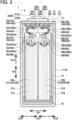
- FIGs. 2 and 3 are cross-sectional views of the battery 1.
- the battery vertical direction AH, the battery lateral direction BH, and the battery thickness direction CH of the battery 1 are defined as indicated with arrows in FIGs. 1 to 3 .
- This battery 1 is a rectangular, sealed lithium-ion secondary battery which can be mounted in a vehicle, such as a hybrid car, a plugin hybrid car, and an electric car.
- the battery 1 includes a case 10, a pair of electrode bodies 20A and 20B housed in the case 10, a positive terminal 50 and a negative terminal 60 each supported in the case 10, and others.
- the electrode bodies 20A and 21B are covered, within the case 10, with a pouch-shaped insulating film 75 opening on one side AH1 in the battery vertical direction AH.
- an electrolytic solution 70 is accommodated, a part of which is impregnated in the electrode bodies 20A and 20B, and another part of which is accumulated on the bottom wall of the case 10.
- the case 10 has a rectangular parallelepiped box-like shape made of metal (e.g., aluminum in the present embodiment), including a case body 11 having a bottom-closed rectangular tubular shape with an opening 11c on the one side AH1 in the battery vertical direction AH, and a case lid 12 having a rectangular plate shape welded to the case body 11 to close the opening 11c.
- metal e.g., aluminum in the present embodiment
- the case lid 12 is fixedly provided with the positive terminal 50 made of aluminum through insulating members 56 and 57, and the positive terminal 50 extends from inside to outside of the case 10.
- This positive terminal 50 includes an inner terminal member 52 having a rectangular plate shape placed inside the case 10, and an outer terminal member 51 that is connected by swaging to the inner terminal member 52 and extends from the inside to the outside of the case 10.
- a positive electrode tab group 38A of the electrode body 20A and a positive tab group 38B of the electrode body 20B are both bonded and electrically conducted.
- the case lid 12 is fixedly provided with the negative terminal 60 made of copper through insulating members 66 and 67, and the negative terminal 60 extends from inside to outside of the case 10.
- This negative terminal 60 includes an inner terminal member 62 having a rectangular plate shape placed inside the case 10, and an outer terminal member 61 that is connected by swaging to the inner terminal member 62 and extends from the inside to the outside of the case 10.
- a negative electrode tab group 48A of the electrode body 20A and a negative electrode tab group 48B of the electrode body 20B are both bonded and electrically conducted.
- the two electrode bodies 20A and 20B are stacked in the electrode body thickness direction DH and accommodated in the case 10. However, the electrode bodies 20A and 20B accommodated in the case 10 are not bound by the case 10 in the electrode body thickness direction DH, but are spaced apart from the case 10.
- the two electrode bodies 20A and 20B are identical in structure, and thus only the electrode body 20A will be described below, accompanied by reference signs of corresponding components or parts of the electrode body 20B in parentheses.
- the electrode body 20A (20B) is a laminated electrode body having a flat, rectangular parallelepiped shape, in which a plurality of rectangular positive electrode sheets 21A (21B) and a plurality of rectangular negative electrode sheets 25A (25B) are alternately stacked with separators 29A (29B) formed of resin porous films interposed therebetween.
- the positive electrode sheets 21A (21B) and the negative electrode sheets 25A (25B) are one examples of electrode sheets of the present disclosure.
- FIG. 4 is a plan view of the positive electrode sheet 21A (21B) and
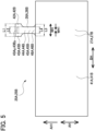
- FIG. 5 is a plan view of the negative electrode sheet 25A (25B).
- the positive electrode sheets 21A (21B) and the separators 29A (29B), overlapping in the electrode body thickness direction DH, are bonded to each other with adhesive, and similarly, the negative electrode sheets 25A (25B) and the separators 29A (29B), overlapping in the electrode body thickness direction DH, are bonded to each other with adhesive. Accordingly, the positive electrode sheets 21A (21B), the negative electrode sheets 25A (25B), and the separators 29A (29B), constituting the electrode body 20A (20B), are integrated together.
- Each of the positive electrode sheets 21A (21B) includes a rectangular plate-shaped positive electrode sheet body 31A (31B) and a positive electrode tab 32A (32B) protruding out on the one side AH1 in the battery vertical direction AH, i.e., upward in FIG. 4 , from the positive electrode sheet body 31A (31B).
- the positive electrode sheet body 31A (32B) and the positive electrode tab 32A (32B) are one examples of an electrode sheet body and an electrode tab of the present disclosure, respectively.
- the positive electrode sheet body 31A (31B) includes a positive current collecting foil 22A (22B) made of an aluminum foil and positive active material layers 23A (23B) provided on both main surfaces of the foil 22A (22B).
- the positive electrode tab 32A (32B) is an extended part of the positive current collecting foil 22A (22B) extending on the one side AH1 in the battery vertical direction AH, the positive current collecting foil 22A (22B) being exposed in the tab thickness direction TH without being coated with the positive active material layers 23A (23B) in the tab thickness direction TH.
- This positive electrode tab group 38A (38B) is bonded to the positive terminal 50 inside the case 10 by ultrasonic welding directly or through another or other positive electrode tabs 32A (32B).
- each of the positive electrode tabs 32A (32B) is an S-shaped electrode tab having two bent portions that bend in the tab thickness direction TH, and includes a tab connection portion 33A (33B), a tab base portion 36A (36B), and a connection-side bent portion 34A (34B) and a base-side bent portion 35A (35B) which join those tab connection portion 33A (33B) and tab base portion 36A (36B).
- the connection-side bent portion 34A (34B) and the base-side bent portion 35A (35B) are one examples of a bent portion of the present disclosure.
- the tab base portion 36A (36B) is a proximal end part of the protruding positive electrode tab 32A (32B) and is continuous with the positive electrode sheet body 31A (31B) and the base-side bent portion 35A (35B) (see FIG. 4 ).
- the tab connection portion 33A (33B) is a distal end part of the protruding positive electrode tab 32A (32B) and includes a welded portion 33Ay (33By) that is located on the inside WH1 in the tab width direction WH and bonded to the positive terminal 50 directly or through another or other positive electrode tabs 32A (32B).
- the welded portion 33Ay (33By) is one example of a bonded portion of the present disclosure.
- the positive electrode tab 32A (32B) in the present embodiment has two bent portions (see FIG. 3 ) as described above, that is, the base-side bent portion 35A (35B) and the connection-side bent portion 34A (34B).
- the base-side bent portion 35A (35B) is a bend located closer to the tab base portion 36A (36B) relative to the connection-side bent portion 34A (34B), i.e., positioned on the proximal end side of the positive electrode tab 32A (32B).
- this base-side bent portion 35A has a shape that extends from the tab base portion 36A (36B) toward the inside CH1 in the battery thickness direction CH, and bends in a U-shape to the outside CH2 in the battery thickness direction CH.
- connection-side bent portion 34A (34B) is a bend located closer to the tab connection portion 33A (33B) relative to the base-side bent portion 35A (35B), i.e., positioned on the distal end side of the positive electrode tab 32A (32B).
- this connection-side bent portion 34A (34B) has a shape that extends from the base-side bent portion 35A (35B) toward the outside CH2 in the battery thickness direction CH, and bends in a U-shape to the inside CH1 in the battery thickness direction CH toward the tab connection portion 33A (33B).
- At least one positive electrode tab 32A (32B) has a shape in which the tab width L2 of the connection-side bent portion 34A (34B) is smaller than the tab width L1 of the tab connection portion 33A (33B), i.e., a shape that satisfies a relationship of L2 ⁇ L1 (see FIG. 4 ).
- the positive electrode tab 32A (32B) configured to satisfy L2 ⁇ L1 is more easily torsionally deformed at the connection-side bent portion 34A (34B), so that the stress generated therein can be reduced, as compared with a battery incorporating positive electrode tabs not configured to satisfy L2 ⁇ L1.
- the battery 1 configured as above can therefore prevent damages such as fissures and fractures at the connection-side bent portion 34A (34B) of the relevant positive electrode tab 32A (32B), and hence suppress the occurrence of defects such as an increase in electrical resistance in the positive electrode tab group 38A (38B).
- a positive electrode tab 32Ac (32Bc) with a connection-side bent portion 34Ac (34Bc) bent with a smallest curvature radius, corresponding to a positive electrode tab located on the most inside CH1 in the battery thickness direction CH has a shape in which the tab width L2 of the connection-side bent portion 34Ac (34Bc) is smaller than the tab width L1 of the tab connection portion 33Ac (33Bc), L2 ⁇ L1, when comparing between the own tab connection portion 33Ac (33Bc) and the own connection-side bent portion 34Ac (34Bc). This can suppress the occurrence of damages to the connection-side bent portion 34Ac (34Bc) that is most likely damaged.
- the positive electrode tabs 32A (32B) that constitute the positive electrode tab group 38A (38B) each have a shape in which the tab width L2 of the connection-side bent portion 34A (34B) is smaller than the tab width L1 of the tab connection portion 33A (33B), L2 ⁇ L1, when comparing between the own tab connection portion 33A (33B) and the own connection-side bent portion 34A (34B). This can prevent damages to the connection-side bent portions 34A (34B) of more than half, and even all, of the positive electrode tabs 32A (32B).
- At least one positive electrode tab 32A (32B) has a shape in which the tab width L4 of the base-side bent portion 35A (35B) is smaller than the tab width L3 of the tab base portion 36A (36B), i.e., a shape that satisfies a relationship of L4 ⁇ L3.
- the positive electrode tab 32A (32B) configured to satisfy L4 ⁇ L3 is more easily torsionally deformed at the base-side bent portion 35A (35B), so that the stress generated therein can be reduced, as compared with a battery incorporating positive electrode tabs not configured to satisfy L4 ⁇ L3.
- the battery 1 configured as above can therefore prevent damages such as fissures and fractures at the base-side bent portion 35A (35B) of the positive electrode tab 32A (32B), and hence suppress the occurrence of defects such as an increase in electrical resistance in the positive electrode tab group 38A (38B).
- a positive electrode tab 32Ad (32Bd) with a base-side bent portion 35Ad (35Bd) bent with a smallest curvature radius which is a positive electrode tab located on the most outside CH2 in the battery thickness direction CH, has a shape in which the tab width L4 of the base-side bent portion 35Ad (35Bd) is smaller than the tab width L3 of the tab base portion 36Ad (36Bd), L4 ⁇ L3, when comparing between the own tab base portion 36Ad (36Bd) and the own base-side bent portion 35Ad (35Bd). This can suppress the occurrence of damages to the base-side bent portion 35Ad (35Bd) that is most likely damaged.
- the positive electrode tabs 32A (32B) that constitute the positive electrode tab group 38A (38B) each have a shape in which the tab width L4 of the base-side bent portion 35A (35B) is smaller than the tab width L3 of the tab base portion 36A (36B), L4 ⁇ L3, when comparing between the own tab base portion 36A (36B) and the own base-side bent portion 35A (35B).
- This can suppress the occurrence of damages to the base-side bent portion 35A (35B) of more than half, and even all, of the positive electrode tabs 32A (32B).
- the electrode body 20A (20B) is not bound by the case 10 in the electrode body thickness direction DH. Accordingly, if the battery 1 is subjected to shocks or vibrations, the electrode body 20A (20B) is more liable to move within the case 10 in the electrode body thickness direction DH, i.e., the battery thickness direction CH, and a direction perpendicular thereto, i.e., the battery vertical direction AH and the battery lateral direction BH, as compared with a battery with an electrode body bound by the case in an electrode body thickness direction.
- the connection-side bent portion 34A (34B) and the base-side bent portion 35A (35B) of each positive electrode tab 32A (32B) are easily damaged.
- the battery 1 is configured such that the positive electrode tab 32A (32B) has a shape that satisfies the relationship of L2 ⁇ L1 or the relationships of L2 ⁇ L1 and L4 ⁇ L3, and thus can significantly suppress the occurrence of defects such as an increase in the electrode resistance in the positive electrode tab group 38A (38B).
- the negative electrode sheets 25A (25B) will be described referring to FIG. 5 .
- the negative electrode sheets 25A (25B), negative electrode tabs 42A (42B), and a negative electrode tab group 48A (48B) are almost identical in structure respectively to the positive electrode sheets 21A (21B), the positive electrode tabs 32A (32B), and the positive electrode tab group 38A (38B), and therefore they will be described below in a simplified manner.
- Each of the negative electrode sheets 25A (25B) includes a negative electrode sheet body 41A (41B), and a negative electrode tab 42A (42B) protruding from the negative electrode sheet body 41A (41B).
- the negative electrode sheet body 41A (41B) and the negative electrode tab 42A (42B) are one examples of an electrode sheet body and an electrode tab of the present disclosure, respectively.
- the negative electrode sheet body 41A (41B) includes a negative current collecting foil 26A (26B) made of a copper foil and negative active material layers 27A (27B) provided on both main surfaces of the foil 26A (26B).
- the negative electrode tab 42A (42B) is an extended part of the negative current collecting foil 26A (26B) extending on the one side AH1 in the battery vertical direction AH, the negative current collecting foil 26A (26B) being exposed in the tab thickness direction TH.
- Each of the negative electrode tabs 42A (42B) includes a tab connection portion 43A (43B), a tab base portion 46A (46B), and a connection-side bent portion 44A (44B) and a base-side bent portion 45A (45B) which join those tab connection portion 43A (43B) and tab base portion 46A (46B).
- connection-side bent portion 44A (44B) and the base-side bent portion 45A (45B) are one example of the bent portion of the present disclosure.
- the tab connection portion 43A (43B) includes a welded portion 43Ay (43By) that is located on the inside WH1 in the tab width direction WH and bonded to the negative terminal 60 directly or through another or other negative electrode tabs 42A (42B).
- the welded portion 43Ay (43By) is one example of the bonded portion of the present disclosure.
- At least one negative electrode tab 42A (42B) has a shape in which the tab width L2 of the connection-side bent portion 44A (44B) is smaller than the tab width L1 of the tab connection portion 43A (43B), i.e., a shape that satisfies a relationship of L2 ⁇ L1 (see FIG. 5 ).
- the negative electrode tab 42A (42B) configured to satisfy L2 ⁇ L1 is more easily torsionally deformed at the connection-side bent portion 44A (44B), so that the stress generated therein can be reduced, as compared with a negative electrode tab not configured to satisfy L2 ⁇ L1.
- the battery 1 configured as above can therefore prevent damages such as fissures and fractures at the connection-side bent portion 44A (44B) of the relevant negative electrode tab 42A (42B), and hence suppress the occurrence of defects such as an increase in electrical resistance in the negative electrode tab group 48A (48B).
- a negative electrode tab 42Ac (42Bc) with a connection-side bent portion 44Ac (44Bc) bent with a smallest curvature radius, corresponding to a negative electrode tab located on the most inside CH1 in the battery thickness direction CH has a shape in which the tab width L2 of the connection-side bent portion 44Ac (44Bc) is smaller than the tab width L1 of the tab connection portion 43Ac (43Bc), L2 ⁇ L1. This can suppress the occurrence of damages to the connection-side bent portion 44Ac (44Bc) that is most likely damaged.
- the negative electrode tabs 42A (42B) that constitute the negative electrode tab group 48A (48B) each have a shape in which the tab width L2 of the connection-side bent portion 44A (44B) is smaller than the tab width L1 of the tab connection portion 43A (43B), L2 ⁇ L1. This can prevent damages to the connection-side bent portions 44A (44B) of more than half, and even all, of the negative electrode tabs 42A (42B).
- At least one negative electrode tab 42A (42B) has a shape in which the tab width L4 of the base-side bent portion 45A (45B) is smaller than the tab width L3 of the tab base portion 46A (46B), i.e., a shape that satisfies a relationship of L4 ⁇ L3.
- the negative electrode tab 42A (42B) configured to satisfy L4 ⁇ L3 is more easily torsionally deformed at the base-side bent portion 45A (45B), so that the stress generated therein can be reduced, as compared with a battery incorporating a negative electrode tab not configured to satisfy L4 ⁇ L3.
- the battery 1 configured as above can therefore prevent damages such as fissures and fractures at the base-side bent portion 45A (45B) of the negative electrode tab 42A (42B), and hence suppress the occurrence of defects such as an increase in electrical resistance in the negative electrode tab group 48A (48B).
- a negative electrode tab 42Ad (42Bd) with a base-side bent portion 45Ad (45Bd) bent with a smallest curvature radius which is a negative electrode tab located on the most outside CH2 in the battery thickness direction CH, has a shape in which the tab width L4 of the base-side bent portion 45Ad (45Bd) is smaller than the tab width L3 of the tab base portion 46Ad (46Bd), L4 ⁇ L3. This can suppress the occurrence of damages to the base-side bent portion 45Ad (45Bd) that is most likely damaged.
- the negative electrode tabs 42A (42B) that constitute the negative electrode tab group 48A (48B) each have a shape in which the tab width L4 of the base-side bent portion 45A (45B) is smaller than the tab width L3 of the tab base portion 46A (46B), L4 ⁇ L3. This can suppress the occurrence of damages to the base-side bent portion 45A (45B) of more than half, and even all, of the negative electrode tab 42A (42B).
- the electrode body 20A (20B) is not bound by the case 10 in the electrode body thickness direction DH. Accordingly, the electrode body 20A (20B) is liable to move within the case 10, which likely causes damages to the connection-side bent portion 44A (44B) and the base-side bent portion 45A (45B) of each negative electrode tab 42A (42B).
- the battery 1 is configured such that the negative electrode tab 42A (42B) has a shape that satisfies the relationship of L2 ⁇ L1 or the relationships of L2 ⁇ L1 and L4 ⁇ L3, and thus can significantly suppress the occurrence of defects such as an increase in the electrode resistance in the negative electrode tab group 48A (48B).
- the positive electrode sheets 21A (21B) and the negative electrode sheets 25A (25B) are alternately laminated, or stacked, with the separators 29A (29B) interposed therebetween to form the electrode body 20A (20B).
- the positive terminal 50 and the negative terminal 60 are fixed to the case lid 12.
- the positive electrode tabs 32A (32B) and the negative electrode tabs 42A (42B) included in the electrode body 20A (20B) are separately overlapped in the tab thickness direction TH, respectively forming the positive electrode tab group 38A (38B) and the negative electrode tab group 48A (48B).
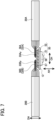
- the tab connection portions 33A (33B) of the positive electrode tab group 38A (38B) and the tab connection portions 43A (43B) of the negative electrode tab group 48A (48B) are respectively welded to the positive terminal 50 and the negative terminal 60 fixed to the case lid 12 (see FIGs. 6 and 7 ).
- the positive electrode tab groups 38A and 38B and the negative electrode tab groups 48A and 48B are each bent in an S-shaped curve and further the two electrode bodies 20A and 20B are stacked in the electrode body thickness direction DH as shown in FIG. 3 .
- the electrode bodies 20A and 20B are enclosed together in the pouch-shaped insulating film 75. These electrode bodies 20A and 20B covered with the insulating film 75 are inserted in the case body 11, and then the opening 11c of this case body 11 is closed with the case lid 12. The case body 11 and the case lid 12 are welded to each other over the entire circumference of the case lid 12, completing the case 10. Successively, the electrolytic solution 70 is injected into the case 10 through an injection port not shown, and then this injection port is sealingly closed with a seal member not shown. This battery 1 is subsequently subjected to initial charging, aging, various inspections, and others to finish the battery 1.
- the foregoing embodiment exemplifies the battery 1 provided with two electrode bodies 20A and 20B housed in the case 10; however, the number of electrode bodies accommodated in the case may be one or three or more. Further, the above embodiment exemplifies the battery 1 provided with the laminated electrode bodies 20A and 20B, but these electrode bodies may be flat wound electrode bodies.
- the foregoing embodiment shows the battery 1 with the case 10 made of metal; however, the case for accommodating an electrode body or bodies is not limited thereto but may be formed of a laminated film or the like.
Landscapes
- Chemical & Material Sciences (AREA)
- Chemical Kinetics & Catalysis (AREA)
- Electrochemistry (AREA)
- General Chemical & Material Sciences (AREA)
- Engineering & Computer Science (AREA)
- Manufacturing & Machinery (AREA)
- Materials Engineering (AREA)
- Connection Of Batteries Or Terminals (AREA)
- Secondary Cells (AREA)
- Sealing Battery Cases Or Jackets (AREA)
Abstract
Description
- The present disclosure relates to a power storage device including a flat electrode body having a tab group in which electrode tabs overlap one another in a tab thickness direction, a case accommodating this electrode body, and an electrode terminal to which the tab group of the electrode body is bonded inside the case.
- Conventionally, there has been known a battery provided with a flat electrode body having a tab group consisting of electrode tabs overlapped in a tab thickness direction, a case, and an electrode terminal that extends from inside to outside of the case. For example, a battery configured as above is disclosed in
Patent Document 1, inFIG. 4 and others. - Patent Document 1:
Japanese unexamined patent application publication No. H11(1999)-016577 - Meanwhile, if the above-mentioned battery is subjected to external shocks or vibrations, the electrode body may be caused to move within the case, resulting in damages, such as fissures or fractures, in the electrode tabs constituting the tab group. Particularly, when each electrode tab includes one or plural bent portions that bend or curve in the tab thickness direction, those electrode tabs are each liable to be torsionally deformed at a bent portion located closest to a bonded portion connected with the electrode terminal, which will also be referred to as a connection-side bent portion, resulting in damages such as fissures and fractures. Damages to the connection-side bent portion(s) of the electrode tab(s) will cause defects such as an increase in electrical resistance in the tab group.
- The present disclosure has been made to address the above problems and has a purpose to provide a power storage device that can suppress the occurrence of defects such as an increase in electrical resistance in a tab group due to damages to the connection-side bent portions of the electrode tabs even when the power storage device is subjected to external shocks or vibrations.
- To achieve the above-mentioned purpose, one aspect of the present disclosure provides (1) a power storage device characterized by comprising: an electrode body having a flat shape and including a plurality of electrode sheets each having an electrode sheet body, and an electrode tab protruding from the electrode sheet body, in which the electrode tabs of the electrode sheets overlap one another in a tab thickness direction to form an electrode tab group; a case in which the electrode body is accommodated; and an electrode terminal that is fixedly provided to the case, extends from inside to outside of the case, and is bonded to the electrode tab group in the case, wherein each of the electrode tabs includes at least one bent portion bent in the tab thickness direction, the electrode tabs constituting the electrode tab group each include a tab connection portion including a bonded portion that is located on an inside in a tab width direction and bonded to the electrode terminal directly or through another or other electrode tabs, and the at least one bent portion includes a connection-side bent portion located close to the tab connection portion, and at least one of the electrode tabs constituting the electrode tab group has a shape in which a tab width (L2) of the connection-side bent portion is smaller than a tab width (L1) of the tab connection portion (L2<L1).
- In the above-described power storage device, among the electrode tabs constituting one tab group, at least one electrode tab has a shape in which, when comparing the tab width between the own tab connection portion and the own connection-side bent portion, the tab width (L2) of the connection-side bent portion is smaller than the tab width (L1) of the tab connection portion; L2<L1. Accordingly, even if the electrode body is caused to move within the case due to shocks or vibrations externally applied to the power storage device, causing the electrode tabs to twist at the connection-side bent portions, the at least one electrode tab configured to satisfy the relationship of L2<L1 is more easily torsionally deformed at the connection-side bent portion, so that the stress generated therein can be reduced, as compared with an electrode tab not configured to satisfy L2<L1, for example, a conventional electrode tab configured to meet L1=L2. The above configuration can prevent damages such as fissures and fractures at the connection-side bent portion of the relevant electrode tab, and hence suppress the occurrence of defects such as an increase in electrical resistance in the tab group.
- The electrode tab may include an electrode tab integrally formed with the electrode sheet body or an electrode tab separately formed from the electrode sheet body and joined thereto by welding. As the electrode tab, each electrode sheet may be provided with a single electrode tab or multiple electrode tabs.
- (2) In the power storage device described in (1), furthermore, among the electrode tabs constituting the electrode tab group, at least an electrode tab with the connection-side bent portion bent with a smallest curvature radius has a shape in which the tab width (L2) of the connection-side bent portion is smaller than the tab width (L1) of the tab connection portion (L2<L1).
- It has been found that, if a power storage device is subjected to external shocks and vibrations, among the connection-side bent portions of the electrode tabs constituting one tab group, the connection-side bent portion bent or curved with a smallest radius of curvature is most likely damaged. To address such defects, the foregoing power storage device is configured such that, among the electrode tabs constituting the tab group, at least the electrode tab having the connection-side bent portion bent with a smallest curvature radius has a shape that satisfies the above-described relationship of L2<L1, when comparing the tab width between the own tab connection portion and the own connection-side bent portion. This configuration can suppress the occurrence of damages at the connection-side bent portion that is most likely damaged, and thus can prevent the defects such as an increase in electrode resistance in the tab group.
- (3) In the power storage device described in (1) or (2), furthermore, more than half of the electrode tabs constituting the electrode tab group each have a shape in which the tab width (L2) of the connection-side bent portion is smaller than the tab width (L1) of the tab connection portion (L2<L1).
- In the above-described power storage device, more than half of the electrode tabs that constitute the tab group each have a shape that satisfies the above-described relationship of L2<L1, when comparing the tab width between the own tab connection portion and the own connection-side bent portion. This configuration can suppress the occurrence of damages at the connection-side bent portions of more than half of the electrode tabs, and thus can more effectively prevent the defects such as an increase in electrode resistance in the tab group.
- Most preferably, the power storage device is configured such that all of the electrode tabs constituting the tab group each have the shape that satisfies the above-described relationship of L2<L1, i.e., a shape in which the tab width (L2) of each of the connection-side bent portions is smaller than the tab width (L1) of each of the tab connection portions, L2<L1.
- (4) In the power storage device described in one of (1) to (3), furthermore, the at least one bent portion of each of the electrode tabs comprises a plurality of bent portions, the electrode tabs constituting the electrode tab group each further include a tab base portion, and the plurality of bent portions include a base-side bent portion located close to the tab base portion, and at least one of the electrode tabs constituting the electrode tab group has a shape in which a tab width (L4) of the base-side bent portion is smaller than a tab width (L3) of the tab base portion (L4<L3).
- It has been found that, if the power storage device provided with the electrode tabs each including a plurality of bent portions is subjected to external shocks and vibrations, each electrode tab is twisted at not only the connection-side bent portion of the bent portions but also the base-side bent portion, easily causing damages such as fissures and fractures. To address such defects, the power storage device described above is configured such that, among the electrode tabs constituting one tab group, at least one electrode tab has a shape in which, when comparing the tab width between the own tab base portion and the own base-side bent portion, the tab width (L4) of the base-side bent portion is smaller than the tab width (L3) of the tab base portion; L4<L3. Accordingly, even if the electrode body is caused to move within the case due to shocks or vibrations externally applied to the power storage device, causing the electrode tabs to twist at the base-side bent portions, the electrode tabs configured to satisfy the relationship of L4<L3 is more easily torsionally deformed at the base-side bent portion and thus can reduce the stress generated therein, as compared with an electrode tab not configured to satisfy L4<L3, for example, a conventional electrode tab configured to meet L3=L4. This configuration can prevent damages such as fissures and fractures at the base-side bent portion of the relevant electrode tab, and hence suppress the occurrence of defects such as an increase in electrical resistance in the tab group.
- (5) In the power storage device described in (4), furthermore, among the electrode tabs constituting the electrode tab group, at least an electrode tab with the base-side bent portion bent with a smallest curvature radius has a shape in which the tab width (L4) of the base-side bent portion is smaller than the tab width (L3) of the tab base portion (L4<L3).
- It has been found that, if a power storage device is subjected to external shocks and vibrations, among base-side bent portions of the electrode tabs constituting one tab group, the base-side bent portion bent or curved with a smallest radius of curvature is most likely damaged. To address such defects, the foregoing power storage device is configured such that, among the the electrode tabs constituting the tab group, at least the electrode tab having the base-side bent portion bent with a smallest curvature radius has a shape that satisfies the above-described relationship of L4<L3, when comparing the tab width between the own tab base portion and the own base-side bent portion. This configuration can suppress the occurrence of damages at the base-side bent portion that is most likely damaged, and thus can prevent the defects such as an increase in electrode resistance in the tab group.
- (6) In the power storage device described in (4) or (5), furthermore, more than half of the electrode tabs constituting the electrode tab group each have a shape in which the tab width (L4) of the base-side bent portion is smaller than the tab width (L3) of the tab base portion (L4<L3).
- In the above-described power storage device, more than half of the electrode tabs constituting the tab group each have a shape that satisfies the above-described relationship of L4<L3, when comparing the tab width between the own tab base portion and the own base-side bent portion. This configuration can suppress the occurrence of damages at the base-side bent portions of more than half of the electrode tabs, and thus can more effectively prevent the defects such as an increase in electrode resistance in the tab group.
- Most preferably, the power storage device is configured such that all of the electrode tabs constituting the tab group each have the shape that satisfies the above-described relationship of L4<L3, i.e., in which the tab width (L4) of each of the base-side bent portions is smaller than the tab width (L3) of each of the tab base portions, L4<L3.
- (7) In the power storage device described in one of (1) to (6), furthermore, the electrode body is accommodated in the case without being bound by the case in an electrode body thickness direction.
- If the above-described power storage device is subjected to external shocks and vibrations, the electrode body is likely caused to move within a case in a thickness direction of the electrode body and in a perpendicular to that thickness direction, as compared with a power storage device in which an electrode body is bound in a thickness direction of the electrode body. Thus, the connection-side bent portion and the base-side bent portion of the electrode tab are likely damaged as described above. In such a power storage device, therefore, the electrode tab configured to satisfy the relationship of L2<L1 or configured to satisfy the relationships of L2<L1 and L4<L3 can particularly achieve a significant advantage of suppressing defects such as an increase in electrode resistance in the tab group.
-
-
FIG. 1 is a perspective view of a battery in an embodiment; -
FIG. 2 is a cross-sectional view of the battery in a battery vertical direction and in a battery lateral direction in the embodiment; -
FIG. 3 is a cross-sectional view of the battery in the battery vertical direction and a battery thickness direction, taken along a line A-A inFIG. 2 , in the embodiment; -
FIG. 4 is a plan view of a positive electrode sheet in the embodiment; -
FIG. 5 is a plan view of a negative electrode sheet in the embodiment; -
FIG. 6 is a plan view showing that positive tab groups and negative tab groups of two electrode bodies are respectively welded to a positive terminal and a negative terminal in a method for producing a battery in the embodiment; and -
FIG. 7 is a cross sectional view taken along a line B-B inFIG. 6 , showing that the positive tab groups and the negative tab groups of two electrode bodies are respectively welded to the positive terminal and the negative terminal in the method for producing a battery in the embodiment. - A detailed description of an embodiment of this disclosure will now be given referring to the accompanying drawings.
FIG. 1 is a perspective view of abattery 1 in the present embodiment, which is one example of a power storage device of the present disclosure.FIGs. 2 and3 are cross-sectional views of thebattery 1. In the following description, the battery vertical direction AH, the battery lateral direction BH, and the battery thickness direction CH of thebattery 1 are defined as indicated with arrows inFIGs. 1 to 3 . Thisbattery 1 is a rectangular, sealed lithium-ion secondary battery which can be mounted in a vehicle, such as a hybrid car, a plugin hybrid car, and an electric car. - The
battery 1 includes acase 10, a pair ofelectrode bodies case 10, apositive terminal 50 and anegative terminal 60 each supported in thecase 10, and others. Theelectrode bodies case 10, with a pouch-shapedinsulating film 75 opening on one side AH1 in the battery vertical direction AH. In thecase 10, further, anelectrolytic solution 70 is accommodated, a part of which is impregnated in theelectrode bodies case 10. - The
case 10 has a rectangular parallelepiped box-like shape made of metal (e.g., aluminum in the present embodiment), including acase body 11 having a bottom-closed rectangular tubular shape with an opening 11c on the one side AH1 in the battery vertical direction AH, and acase lid 12 having a rectangular plate shape welded to thecase body 11 to close the opening 11c. - The
case lid 12 is fixedly provided with thepositive terminal 50 made of aluminum through insulatingmembers positive terminal 50 extends from inside to outside of thecase 10. Thispositive terminal 50 includes aninner terminal member 52 having a rectangular plate shape placed inside thecase 10, and anouter terminal member 51 that is connected by swaging to theinner terminal member 52 and extends from the inside to the outside of thecase 10. To theinner terminal member 52, a positiveelectrode tab group 38A of theelectrode body 20A and apositive tab group 38B of theelectrode body 20B are both bonded and electrically conducted. - Furthermore, the
case lid 12 is fixedly provided with thenegative terminal 60 made of copper through insulatingmembers negative terminal 60 extends from inside to outside of thecase 10. Thisnegative terminal 60 includes aninner terminal member 62 having a rectangular plate shape placed inside thecase 10, and anouter terminal member 61 that is connected by swaging to theinner terminal member 62 and extends from the inside to the outside of thecase 10. To theinner terminal member 62, a negativeelectrode tab group 48A of theelectrode body 20A and a negativeelectrode tab group 48B of theelectrode body 20B are both bonded and electrically conducted. - The two
electrode bodies case 10. However, theelectrode bodies case 10 are not bound by thecase 10 in the electrode body thickness direction DH, but are spaced apart from thecase 10. The twoelectrode bodies electrode body 20A will be described below, accompanied by reference signs of corresponding components or parts of theelectrode body 20B in parentheses. Theelectrode body 20A (20B) is a laminated electrode body having a flat, rectangular parallelepiped shape, in which a plurality of rectangularpositive electrode sheets 21A (21B) and a plurality of rectangularnegative electrode sheets 25A (25B) are alternately stacked withseparators 29A (29B) formed of resin porous films interposed therebetween. Thepositive electrode sheets 21A (21B) and thenegative electrode sheets 25A (25B) are one examples of electrode sheets of the present disclosure.FIG. 4 is a plan view of thepositive electrode sheet 21A (21B) andFIG. 5 is a plan view of thenegative electrode sheet 25A (25B). Thepositive electrode sheets 21A (21B) and theseparators 29A (29B), overlapping in the electrode body thickness direction DH, are bonded to each other with adhesive, and similarly, thenegative electrode sheets 25A (25B) and theseparators 29A (29B), overlapping in the electrode body thickness direction DH, are bonded to each other with adhesive. Accordingly, thepositive electrode sheets 21A (21B), thenegative electrode sheets 25A (25B), and theseparators 29A (29B), constituting theelectrode body 20A (20B), are integrated together. - Each of the
positive electrode sheets 21A (21B) (seeFIG. 4 ) includes a rectangular plate-shaped positiveelectrode sheet body 31A (31B) and apositive electrode tab 32A (32B) protruding out on the one side AH1 in the battery vertical direction AH, i.e., upward inFIG. 4 , from the positiveelectrode sheet body 31A (31B). The positiveelectrode sheet body 31A (32B) and thepositive electrode tab 32A (32B) are one examples of an electrode sheet body and an electrode tab of the present disclosure, respectively. The positiveelectrode sheet body 31A (31B) includes a positive current collectingfoil 22A (22B) made of an aluminum foil and positiveactive material layers 23A (23B) provided on both main surfaces of thefoil 22A (22B). Thepositive electrode tab 32A (32B) is an extended part of the positive current collectingfoil 22A (22B) extending on the one side AH1 in the battery vertical direction AH, the positive current collectingfoil 22A (22B) being exposed in the tab thickness direction TH without being coated with the positiveactive material layers 23A (23B) in the tab thickness direction TH. - The
positive electrode tabs 32A (32B) of thepositive electrode sheets 21A (21B) included in theelectrode body 20A (20B) overlap one another in the tab thickness direction TH, forming the positiveelectrode tab group 38A (38B), as shown inFIG. 3 . This positiveelectrode tab group 38A (38B) is bonded to thepositive terminal 50 inside thecase 10 by ultrasonic welding directly or through another or otherpositive electrode tabs 32A (32B). In the present embodiment, each of thepositive electrode tabs 32A (32B) is an S-shaped electrode tab having two bent portions that bend in the tab thickness direction TH, and includes atab connection portion 33A (33B), atab base portion 36A (36B), and a connection-sidebent portion 34A (34B) and a base-sidebent portion 35A (35B) which join thosetab connection portion 33A (33B) andtab base portion 36A (36B). The connection-sidebent portion 34A (34B) and the base-sidebent portion 35A (35B) are one examples of a bent portion of the present disclosure. - The
tab base portion 36A (36B) is a proximal end part of the protrudingpositive electrode tab 32A (32B) and is continuous with the positiveelectrode sheet body 31A (31B) and the base-sidebent portion 35A (35B) (seeFIG. 4 ). - In contrast, the
tab connection portion 33A (33B) is a distal end part of the protrudingpositive electrode tab 32A (32B) and includes a welded portion 33Ay (33By) that is located on the inside WH1 in the tab width direction WH and bonded to thepositive terminal 50 directly or through another or otherpositive electrode tabs 32A (32B). The welded portion 33Ay (33By) is one example of a bonded portion of the present disclosure. - The
positive electrode tab 32A (32B) in the present embodiment has two bent portions (seeFIG. 3 ) as described above, that is, the base-sidebent portion 35A (35B) and the connection-sidebent portion 34A (34B). The base-sidebent portion 35A (35B) is a bend located closer to thetab base portion 36A (36B) relative to the connection-sidebent portion 34A (34B), i.e., positioned on the proximal end side of thepositive electrode tab 32A (32B). Specifically, this base-sidebent portion 35A has a shape that extends from thetab base portion 36A (36B) toward the inside CH1 in the battery thickness direction CH, and bends in a U-shape to the outside CH2 in the battery thickness direction CH. - In contrast, the connection-side
bent portion 34A (34B) is a bend located closer to thetab connection portion 33A (33B) relative to the base-sidebent portion 35A (35B), i.e., positioned on the distal end side of thepositive electrode tab 32A (32B). Specifically, this connection-sidebent portion 34A (34B) has a shape that extends from the base-sidebent portion 35A (35B) toward the outside CH2 in the battery thickness direction CH, and bends in a U-shape to the inside CH1 in the battery thickness direction CH toward thetab connection portion 33A (33B). - In the
battery 1, among thepositive electrode tabs 32A (32B) constituting the positiveelectrode tab group 38A (38B), at least onepositive electrode tab 32A (32B) has a shape in which the tab width L2 of the connection-sidebent portion 34A (34B) is smaller than the tab width L1 of thetab connection portion 33A (33B), i.e., a shape that satisfies a relationship of L2<L1 (seeFIG. 4 ). Accordingly, even if theelectrode body 20A (20B) is caused to move within thecase 10 due to external shocks or vibrations externally applied to thebattery 1, causing thepositive electrode tabs 32A (32B) to twist at the connection-sidebent portions 34A (34B), thepositive electrode tab 32A (32B) configured to satisfy L2<L1 is more easily torsionally deformed at the connection-sidebent portion 34A (34B), so that the stress generated therein can be reduced, as compared with a battery incorporating positive electrode tabs not configured to satisfy L2<L1. Thebattery 1 configured as above can therefore prevent damages such as fissures and fractures at the connection-sidebent portion 34A (34B) of the relevantpositive electrode tab 32A (32B), and hence suppress the occurrence of defects such as an increase in electrical resistance in the positiveelectrode tab group 38A (38B). - In the present embodiment, particularly, among the
positive electrode tabs 32A (32B) of the positiveelectrode tab group 38A (38B), a positive electrode tab 32Ac (32Bc) with a connection-side bent portion 34Ac (34Bc) bent with a smallest curvature radius, corresponding to a positive electrode tab located on the most inside CH1 in the battery thickness direction CH, has a shape in which the tab width L2 of the connection-side bent portion 34Ac (34Bc) is smaller than the tab width L1 of the tab connection portion 33Ac (33Bc), L2<L1, when comparing between the own tab connection portion 33Ac (33Bc) and the own connection-side bent portion 34Ac (34Bc). This can suppress the occurrence of damages to the connection-side bent portion 34Ac (34Bc) that is most likely damaged. - In the present embodiment, furthermore, more than half, and even all, of the
positive electrode tabs 32A (32B) that constitute the positiveelectrode tab group 38A (38B) each have a shape in which the tab width L2 of the connection-sidebent portion 34A (34B) is smaller than the tab width L1 of thetab connection portion 33A (33B), L2<L1, when comparing between the owntab connection portion 33A (33B) and the own connection-sidebent portion 34A (34B). This can prevent damages to the connection-sidebent portions 34A (34B) of more than half, and even all, of thepositive electrode tabs 32A (32B). - In the
battery 1, among thepositive electrode tabs 32A (32B) constituting the positiveelectrode tab group 38A (38B), at least onepositive electrode tab 32A (32B) has a shape in which the tab width L4 of the base-sidebent portion 35A (35B) is smaller than the tab width L3 of thetab base portion 36A (36B), i.e., a shape that satisfies a relationship of L4<L3. Accordingly, even if thepositive electrode tab 32A (32B) is twisted at the base-sidebent portion 35A (35B) due to external shocks or vibrations applied to thebattery 1, thepositive electrode tab 32A (32B) configured to satisfy L4<L3 is more easily torsionally deformed at the base-sidebent portion 35A (35B), so that the stress generated therein can be reduced, as compared with a battery incorporating positive electrode tabs not configured to satisfy L4<L3. Thebattery 1 configured as above can therefore prevent damages such as fissures and fractures at the base-sidebent portion 35A (35B) of thepositive electrode tab 32A (32B), and hence suppress the occurrence of defects such as an increase in electrical resistance in the positiveelectrode tab group 38A (38B). - In the present embodiment, particularly, among the
positive electrode tab 32A (32B) constituting the positiveelectrode tab group 38A (38B), a positive electrode tab 32Ad (32Bd) with a base-side bent portion 35Ad (35Bd) bent with a smallest curvature radius, which is a positive electrode tab located on the most outside CH2 in the battery thickness direction CH, has a shape in which the tab width L4 of the base-side bent portion 35Ad (35Bd) is smaller than the tab width L3 of the tab base portion 36Ad (36Bd), L4<L3, when comparing between the own tab base portion 36Ad (36Bd) and the own base-side bent portion 35Ad (35Bd). This can suppress the occurrence of damages to the base-side bent portion 35Ad (35Bd) that is most likely damaged. - In the present embodiment, furthermore, more than half, and even all, of the
positive electrode tabs 32A (32B) that constitute the positiveelectrode tab group 38A (38B) each have a shape in which the tab width L4 of the base-sidebent portion 35A (35B) is smaller than the tab width L3 of thetab base portion 36A (36B), L4<L3, when comparing between the owntab base portion 36A (36B) and the own base-sidebent portion 35A (35B). This can suppress the occurrence of damages to the base-sidebent portion 35A (35B) of more than half, and even all, of thepositive electrode tabs 32A (32B). - In the present embodiment, the
electrode body 20A (20B) is not bound by thecase 10 in the electrode body thickness direction DH. Accordingly, if thebattery 1 is subjected to shocks or vibrations, theelectrode body 20A (20B) is more liable to move within thecase 10 in the electrode body thickness direction DH, i.e., the battery thickness direction CH, and a direction perpendicular thereto, i.e., the battery vertical direction AH and the battery lateral direction BH, as compared with a battery with an electrode body bound by the case in an electrode body thickness direction. Thus, the connection-sidebent portion 34A (34B) and the base-sidebent portion 35A (35B) of eachpositive electrode tab 32A (32B) are easily damaged. To avoid such defects, thebattery 1 is configured such that thepositive electrode tab 32A (32B) has a shape that satisfies the relationship of L2<L1 or the relationships of L2<L1 and L4<L3, and thus can significantly suppress the occurrence of defects such as an increase in the electrode resistance in the positiveelectrode tab group 38A (38B). - Next, the
negative electrode sheets 25A (25B) will be described referring toFIG. 5 . Thenegative electrode sheets 25A (25B),negative electrode tabs 42A (42B), and a negativeelectrode tab group 48A (48B) are almost identical in structure respectively to thepositive electrode sheets 21A (21B), thepositive electrode tabs 32A (32B), and the positiveelectrode tab group 38A (38B), and therefore they will be described below in a simplified manner. Each of thenegative electrode sheets 25A (25B) includes a negativeelectrode sheet body 41A (41B), and anegative electrode tab 42A (42B) protruding from the negativeelectrode sheet body 41A (41B). The negativeelectrode sheet body 41A (41B) and thenegative electrode tab 42A (42B) are one examples of an electrode sheet body and an electrode tab of the present disclosure, respectively. The negativeelectrode sheet body 41A (41B) includes a negativecurrent collecting foil 26A (26B) made of a copper foil and negativeactive material layers 27A (27B) provided on both main surfaces of thefoil 26A (26B). Thenegative electrode tab 42A (42B) is an extended part of the negativecurrent collecting foil 26A (26B) extending on the one side AH1 in the battery vertical direction AH, the negativecurrent collecting foil 26A (26B) being exposed in the tab thickness direction TH. - The
negative electrode tabs 42A (42B) of thenegative electrode sheets 25A (25B) included in theelectrode body 20A (20B) overlap one another in the tab thickness direction TH, forming the negativeelectrode tab group 48A (48B), which is bonded to thenegative terminal 60 inside thecase 10, as shown inFIG. 3 . Each of thenegative electrode tabs 42A (42B) includes atab connection portion 43A (43B), atab base portion 46A (46B), and a connection-sidebent portion 44A (44B) and a base-sidebent portion 45A (45B) which join thosetab connection portion 43A (43B) andtab base portion 46A (46B). The connection-sidebent portion 44A (44B) and the base-sidebent portion 45A (45B) are one example of the bent portion of the present disclosure. Thetab connection portion 43A (43B) includes a welded portion 43Ay (43By) that is located on the inside WH1 in the tab width direction WH and bonded to thenegative terminal 60 directly or through another or othernegative electrode tabs 42A (42B). The welded portion 43Ay (43By) is one example of the bonded portion of the present disclosure. - In the
battery 1, among thenegative electrode tabs 42A (42B) constituting the negativeelectrode tab group 48A (48B), at least onenegative electrode tab 42A (42B) has a shape in which the tab width L2 of the connection-sidebent portion 44A (44B) is smaller than the tab width L1 of thetab connection portion 43A (43B), i.e., a shape that satisfies a relationship of L2<L1 (seeFIG. 5 ). Accordingly, even if thenegative electrode tab 42A (42B) is twisted at the connection-sidebent portion 44A (44B) due to external shocks or vibrations externally applied to thebattery 1, thenegative electrode tab 42A (42B) configured to satisfy L2<L1 is more easily torsionally deformed at the connection-sidebent portion 44A (44B), so that the stress generated therein can be reduced, as compared with a negative electrode tab not configured to satisfy L2<L1. Thebattery 1 configured as above can therefore prevent damages such as fissures and fractures at the connection-sidebent portion 44A (44B) of the relevantnegative electrode tab 42A (42B), and hence suppress the occurrence of defects such as an increase in electrical resistance in the negativeelectrode tab group 48A (48B). - In the present embodiment, particularly, among the
negative electrode tabs 42A (42B) of the negativeelectrode tab group 48A (48B), a negative electrode tab 42Ac (42Bc) with a connection-side bent portion 44Ac (44Bc) bent with a smallest curvature radius, corresponding to a negative electrode tab located on the most inside CH1 in the battery thickness direction CH, has a shape in which the tab width L2 of the connection-side bent portion 44Ac (44Bc) is smaller than the tab width L1 of the tab connection portion 43Ac (43Bc), L2<L1. This can suppress the occurrence of damages to the connection-side bent portion 44Ac (44Bc) that is most likely damaged. - In the present embodiment, furthermore, more than half, and even all, of the
negative electrode tabs 42A (42B) that constitute the negativeelectrode tab group 48A (48B) each have a shape in which the tab width L2 of the connection-sidebent portion 44A (44B) is smaller than the tab width L1 of thetab connection portion 43A (43B), L2<L1. This can prevent damages to the connection-sidebent portions 44A (44B) of more than half, and even all, of thenegative electrode tabs 42A (42B). - In the
battery 1, among thenegative electrode tabs 42A (42B) constituting the negativeelectrode tab group 48A (48B), at least onenegative electrode tab 42A (42B) has a shape in which the tab width L4 of the base-sidebent portion 45A (45B) is smaller than the tab width L3 of thetab base portion 46A (46B), i.e., a shape that satisfies a relationship of L4<L3. Accordingly, even if thenegative electrode tab 42A (42B) is twisted at the base-sidebent portion 45A (45B) due to external shocks or vibrations applied to thebattery 1, thenegative electrode tab 42A (42B) configured to satisfy L4<L3 is more easily torsionally deformed at the base-sidebent portion 45A (45B), so that the stress generated therein can be reduced, as compared with a battery incorporating a negative electrode tab not configured to satisfy L4<L3. Thebattery 1 configured as above can therefore prevent damages such as fissures and fractures at the base-sidebent portion 45A (45B) of thenegative electrode tab 42A (42B), and hence suppress the occurrence of defects such as an increase in electrical resistance in the negativeelectrode tab group 48A (48B). - In the present embodiment, particularly, among the
negative electrode tabs 42A (42B) constituting the negativeelectrode tab group 48A (48B), a negative electrode tab 42Ad (42Bd) with a base-side bent portion 45Ad (45Bd) bent with a smallest curvature radius, which is a negative electrode tab located on the most outside CH2 in the battery thickness direction CH, has a shape in which the tab width L4 of the base-side bent portion 45Ad (45Bd) is smaller than the tab width L3 of the tab base portion 46Ad (46Bd), L4<L3. This can suppress the occurrence of damages to the base-side bent portion 45Ad (45Bd) that is most likely damaged. - In the present embodiment, furthermore, more than half, and even all, of the
negative electrode tabs 42A (42B) that constitute the negativeelectrode tab group 48A (48B) each have a shape in which the tab width L4 of the base-sidebent portion 45A (45B) is smaller than the tab width L3 of thetab base portion 46A (46B), L4<L3. This can suppress the occurrence of damages to the base-sidebent portion 45A (45B) of more than half, and even all, of thenegative electrode tab 42A (42B). - In the present embodiment, the
electrode body 20A (20B) is not bound by thecase 10 in the electrode body thickness direction DH. Accordingly, theelectrode body 20A (20B) is liable to move within thecase 10, which likely causes damages to the connection-sidebent portion 44A (44B) and the base-sidebent portion 45A (45B) of eachnegative electrode tab 42A (42B). To avoid such defects, thebattery 1 is configured such that thenegative electrode tab 42A (42B) has a shape that satisfies the relationship of L2<L1 or the relationships of L2<L1 and L4<L3, and thus can significantly suppress the occurrence of defects such as an increase in the electrode resistance in the negativeelectrode tab group 48A (48B). - Next, a method for producing the above-described
battery 1 will be described below. Firstly, thepositive electrode sheets 21A (21B) and thenegative electrode sheets 25A (25B) are alternately laminated, or stacked, with theseparators 29A (29B) interposed therebetween to form theelectrode body 20A (20B). Separately, thepositive terminal 50 and thenegative terminal 60 are fixed to thecase lid 12. - Subsequently, the
positive electrode tabs 32A (32B) and thenegative electrode tabs 42A (42B) included in theelectrode body 20A (20B) are separately overlapped in the tab thickness direction TH, respectively forming the positiveelectrode tab group 38A (38B) and the negativeelectrode tab group 48A (48B). Then, thetab connection portions 33A (33B) of the positiveelectrode tab group 38A (38B) and thetab connection portions 43A (43B) of the negativeelectrode tab group 48A (48B) are respectively welded to thepositive terminal 50 and thenegative terminal 60 fixed to the case lid 12 (seeFIGs. 6 and7 ). Thereafter, the positiveelectrode tab groups electrode tab groups electrode bodies FIG. 3 . - The
electrode bodies film 75. Theseelectrode bodies film 75 are inserted in thecase body 11, and then theopening 11c of thiscase body 11 is closed with thecase lid 12. Thecase body 11 and thecase lid 12 are welded to each other over the entire circumference of thecase lid 12, completing thecase 10. Successively, theelectrolytic solution 70 is injected into thecase 10 through an injection port not shown, and then this injection port is sealingly closed with a seal member not shown. Thisbattery 1 is subsequently subjected to initial charging, aging, various inspections, and others to finish thebattery 1. - The present disclosure is described in the foregoing embodiment, but is not limited thereto. The present disclosure may be embodied in other specific forms without departing from the essential characteristics thereof.
- For example, the foregoing embodiment exemplifies the
battery 1 provided with twoelectrode bodies case 10; however, the number of electrode bodies accommodated in the case may be one or three or more. Further, the above embodiment exemplifies thebattery 1 provided with thelaminated electrode bodies - Further, the foregoing embodiment shows the
battery 1 with thecase 10 made of metal; however, the case for accommodating an electrode body or bodies is not limited thereto but may be formed of a laminated film or the like. -
- 1
- Battery (Power storage device)
- 10
- Case
- 20A, 20B
- Electrode body
- 21A,21B
- Positive electrode sheet (Electrode sheet)
- 25A,25B
- Negative electrode sheet (Electrode sheet)
- 31A,31B
- Positive electrode sheet body (Electrode sheet body)
- 32A,321B
- Positive electrode tab (Electrode tab)
- 32Ac,32Bc
- Positive electrode tab (Electrode tab, with a connection-side bent portion having a smallest curvature radius)
- 32Ad,32Bd
- Positive electrode tab (Electrode tab, with a base-side bent portion having a smallest curvature radius)
- 34A, 34B, 33Ac, 33Bc
- Tab connection portion
- 33Ay, 33By
- Welded portion (Bonded portion)
- 34A, 34B
- Connection-side bent portion (Bent portion)
- 34Ac, 34Bc
- Connection-side bent portion (Bent portion, having a smallest curvature radius)
- 35A, 35B
- Base-side bent portion (Bent portion)
- 35Ad, 35Bd
- Base-side bent portion (Bent portion, having a smallest curvature radius)
- 36A, 36B, 36Ad, 36Bd
- Tab base portion
- 38A, 38B
- Positive electrode tab group (Tab group)
- 41A, 41B
- Negative electrode sheet body (Electrode body)
- 42A, 42B
- Negative electrode tab (Electrode tab)
- 42Ac, 42Bc
- Negative electrode tab (Electrode tab, with a connection-side bent portion having a smallest curvature radius)
- 42Ad, 42Bd
- Negative electrode tab (Electrode tab, with a base-side bent portion having a smallest curvature radius)
- 43A, 43B, 43Ac, 43Bc
- Tab connection portion
- 43Ay, 43By
- Welded portion (Bonded portion)
- 44A, 44B
- Connection-side bent portion (Bent portion)
- 44Ac, 44Bc
- Connection-side bent portion (Bent portion, having a smallest curvature radius)
- 45A, 45B
- Base-side bent portion (Bent portion)
- 45Ad,45Bd
- Base-side bent portion (Bent portion, having a smallest curvature radius)
- 46A, 46B, 46Ad, 46Bd
- Tab base portion
- 48A, 48B
- Negative electrode tab group (Tab group)
- 50
- Positive terminal
- 60
- Negative terminal
- TH
- Tab thickness direction
- WH
- Tab width direction
- WH1
- Inside in tab width direction
- L1
- Tab width (of tab connection portion)
- L2
- Tab width (of connection-side bent portion)
- L3
- Tab width (of tab base portion)
- L4
- Tab width (of base-side bent portion)
Claims (7)
- A power storage device (1) characterized by comprising:an electrode body (20A, 20B) having a flat shape and including a plurality of electrode sheets (21A, 21B, 25A, 25B) each having an electrode sheet body (31A, 31B, 41A, 41B), and an electrode tab (32A, 32B, 42A, 42B) protruding from the electrode sheet body (31A, 31B, 41A, 41B), in which the electrode tabs (32A, 32B, 42A, 42B) of the electrode sheets (21A, 21B, 25A, 25B) overlap one another in a tab thickness direction (TH) to form an electrode tab group (38A, 38B, 48A, 48B);a case (10) in which the electrode body (20A, 20B) is accommodated; andan electrode terminal (50, 60) that is fixedly provided to the case (10), extends from inside to outside of the case (10), and is bonded to the electrode tab group (38A, 38B, 48A, 48B) in the case (10),wherein each of the electrode tabs (32A, 32B, 42A, 42B) includes at least one bent portion (34A, 34B, 35A, 35B, 44A, 44B, 45A, 45B) bent in the tab thickness direction (TH),the electrode tabs (32A, 32B, 42A, 42B) constituting the electrode tab group (38A, 38B, 48A, 48B) each include a tab connection portion (33A, 33B, 43A, 43B) including a bonded portion (33Ay,33By, 43Ay, 43By) that is located on an inside (WH1) in a tab width direction (WH) and bonded to the electrode terminal (50, 60) directly or through another or other electrode tabs (32A, 32B, 42A, 42B), and the at least one bent portion (34A, 34B, 35A, 35B, 44A, 44B, 45A, 45B) includes a connection-side bent portion (34A, 34B, 44A, 44B) located close to the tab connection portion (33A, 33B, 43A, 43B), andat least one of the electrode tabs (32A, 32B, 42A, 42B) constituting the electrode tab group (38A, 38B, 48A, 48B) has a shape in which a tab width (L2) of the connection-side bent portion (34A, 34B, 44A, 44B) is smaller than a tab width (L1) of the tab connection portion (33A, 33B, 43A, 43B) (L2<L1).
- The power storage device (1) according to 1, wherein
among the electrode tabs (32A, 32B, 42A, 42B) constituting the electrode tab group (38A, 38B, 48A, 48B), at least an electrode tab (32Ac, 32Bc, 42Ac, 42Bc) with the connection-side bent portion (34A, 34B, 44A, 44B) bent with a smallest curvature radius has a shape in which the tab width (L2) of the connection-side bent portion (34Ac, 34Bc, 44Ac, 44Bc) is smaller than the tab width (L1) of the tab connection portion (33Ac, 33Bc, 43Ac, 43Bc) (L2<L1). - The power storage device (1) according to claim 1 or 2, wherein
more than half of the electrode tabs (32A, 32B, 42A, 42B) constituting the electrode tab group (38A, 38B, 48A, 48B) each have a shape in which the tab width (L2) of the connection-side bent portion (34A, 34B, 44A, 44B) is smaller than the tab width (L1) of the tab connection portion (33A, 33B, 43A, 43B) (L2<L1). - The power storage device (1) according to one of claims 1 to 3, whereinthe at least one bent portion of each of the electrode tabs (32A, 32B, 42A, 42B) comprises a plurality of bent portions (34A, 34B, 35A, 35B, 44A, 44B, 45A, 45B),the electrode tabs (32A, 32B, 42A, 42B) constituting the electrode tab group (38A, 38B, 48A, 48B) each further include a tab base portion (36A, 36B, 46A, 46B),the plurality of bent portions (34A, 34B, 35A, 35B, 44A, 44B, 45A, 45B) include a base-side bent portion (35A, 35B, 45A, 45B) located closest to the tab base portion (36A, 36B, 46A, 46B), andat least one of the electrode tabs (32A, 32B, 42A, 42B) constituting the electrode tab group (38A, 38B, 48A, 48B) has a shape in which a tab width (L4) of the base-side bent portion (35A, 35B, 45A, 45B) is smaller than a tab width (L3) of the tab base portion (36A, 36B, 46A, 46B) (L4<L3).
- The power storage device (1) according to claim 4, wherein
among the electrode tabs (32A, 32B, 42A, 42B) constituting the electrode tab group (38A, 38B, 48A, 48B), at least an electrode tab (32Ad, 32Bd, 42Ad, 42Bd) with the base-side bent portion (35A, 35B, 45A, 45B) bent with a smallest curvature radius has a shape in which the tab width (L4) of the base-side bent portion (35Ad, 35Bd, 45Ad, 45Bd) is smaller than the tab width (L3) of the tab base portion (36Ad, 36Bd, 46Ad, 46Bd) (L4<L3). - The power storage device (1) according to claim 4 or 5, wherein
more than half of the electrode tabs (32A, 32B, 42A, 42B) constituting the electrode tab group (38A, 38B, 48A, 48B) each have a shape in which the tab width (L4) of the base-side bent portion (35A, 35B, 45A, 45B) is smaller than the tab width (L3) of the tab base portion (36A, 36B, 46A, 46B) (L4<L3). - The power storage device (1) according to one of claims 1 to 6, wherein
the electrode body (20A, 20B) is accommodated in the case (10) without being bound by the case (10) in an electrode body thickness direction (DH).
Applications Claiming Priority (1)
| Application Number | Priority Date | Filing Date | Title |
|---|---|---|---|
| JP2022054448A JP7535075B2 (en) | 2022-03-29 | 2022-03-29 | Energy Storage Devices |
Publications (2)
| Publication Number | Publication Date |
|---|---|
| EP4254642A1 true EP4254642A1 (en) | 2023-10-04 |
| EP4254642B1 EP4254642B1 (en) | 2025-05-07 |
Family
ID=84358451
Family Applications (1)
| Application Number | Title | Priority Date | Filing Date |
|---|---|---|---|
| EP22208069.9A Active EP4254642B1 (en) | 2022-03-29 | 2022-11-17 | Power storage device |
Country Status (5)
| Country | Link |
|---|---|
| US (1) | US12562438B2 (en) |
| EP (1) | EP4254642B1 (en) |
| JP (1) | JP7535075B2 (en) |
| KR (1) | KR102915040B1 (en) |
| CN (1) | CN116895916A (en) |
Families Citing this family (1)
| Publication number | Priority date | Publication date | Assignee | Title |
|---|---|---|---|---|
| CN119601571A (en) * | 2024-11-21 | 2025-03-11 | 湖北亿纬动力有限公司 | Electrode, battery cell, battery pack and electrode design method |
Citations (6)
| Publication number | Priority date | Publication date | Assignee | Title |
|---|---|---|---|---|
| JPH1116577A (en) | 1997-06-26 | 1999-01-22 | Shin Kobe Electric Mach Co Ltd | Non-aqueous electrolyte battery |
| JP2015106534A (en) * | 2013-12-02 | 2015-06-08 | 株式会社豊田自動織機 | Power storage device |
| JP2019121433A (en) * | 2017-12-28 | 2019-07-22 | 株式会社豊田自動織機 | Power storage device |
| US10665829B2 (en) * | 2017-06-23 | 2020-05-26 | Sanyo Electric Co., Ltd. | Rectangular secondary battery and method of manufacturing the same |
| US20200266493A1 (en) * | 2019-02-18 | 2020-08-20 | Sanyo Electric Co., Ltd. | Secondary battery |
| WO2021124797A1 (en) * | 2019-12-19 | 2021-06-24 | パナソニック株式会社 | Non-aqueous electrolyte secondary battery |
Family Cites Families (10)
| Publication number | Priority date | Publication date | Assignee | Title |
|---|---|---|---|---|
| JPH05121064A (en) * | 1991-10-31 | 1993-05-18 | Matsushita Electric Ind Co Ltd | Cylindrical battery |
| JPH07226197A (en) * | 1994-02-09 | 1995-08-22 | Matsushita Electric Ind Co Ltd | Battery |
| KR101156955B1 (en) * | 2007-06-14 | 2012-06-20 | 주식회사 엘지화학 | Electrode Assembly of Improved Stability and Secondary Battery Comprising the Same |
| JP5334429B2 (en) * | 2008-03-13 | 2013-11-06 | 日立ビークルエナジー株式会社 | Lithium secondary battery |
| JP2012014935A (en) * | 2010-06-30 | 2012-01-19 | Mitsubishi Heavy Ind Ltd | Battery |
| KR101134122B1 (en) * | 2011-08-30 | 2012-04-09 | (주)열린기술 | Large capacity secondary battery |
| WO2014054733A1 (en) * | 2012-10-03 | 2014-04-10 | 新神戸電機株式会社 | Secondary battery |
| JP6582500B2 (en) * | 2015-03-31 | 2019-10-02 | 株式会社Gsユアサ | Electricity storage element |
| JP7459029B2 (en) * | 2021-08-25 | 2024-04-01 | プライムプラネットエナジー&ソリューションズ株式会社 | Battery and method for manufacturing the battery |
| JP7672375B2 (en) * | 2022-10-21 | 2025-05-07 | プライムプラネットエナジー&ソリューションズ株式会社 | battery |
-
2022
- 2022-03-29 JP JP2022054448A patent/JP7535075B2/en active Active
- 2022-11-17 EP EP22208069.9A patent/EP4254642B1/en active Active
- 2022-12-07 US US18/076,764 patent/US12562438B2/en active Active
-
2023
- 2023-01-05 CN CN202310011228.XA patent/CN116895916A/en active Pending
- 2023-02-02 KR KR1020230014054A patent/KR102915040B1/en active Active
Patent Citations (6)
| Publication number | Priority date | Publication date | Assignee | Title |
|---|---|---|---|---|
| JPH1116577A (en) | 1997-06-26 | 1999-01-22 | Shin Kobe Electric Mach Co Ltd | Non-aqueous electrolyte battery |
| JP2015106534A (en) * | 2013-12-02 | 2015-06-08 | 株式会社豊田自動織機 | Power storage device |
| US10665829B2 (en) * | 2017-06-23 | 2020-05-26 | Sanyo Electric Co., Ltd. | Rectangular secondary battery and method of manufacturing the same |
| JP2019121433A (en) * | 2017-12-28 | 2019-07-22 | 株式会社豊田自動織機 | Power storage device |
| US20200266493A1 (en) * | 2019-02-18 | 2020-08-20 | Sanyo Electric Co., Ltd. | Secondary battery |
| WO2021124797A1 (en) * | 2019-12-19 | 2021-06-24 | パナソニック株式会社 | Non-aqueous electrolyte secondary battery |
Also Published As
| Publication number | Publication date |
|---|---|
| US12562438B2 (en) | 2026-02-24 |
| KR20230140354A (en) | 2023-10-06 |
| KR102915040B1 (en) | 2026-01-20 |
| CN116895916A (en) | 2023-10-17 |
| US20230318150A1 (en) | 2023-10-05 |
| EP4254642B1 (en) | 2025-05-07 |
| JP2023146969A (en) | 2023-10-12 |
| JP7535075B2 (en) | 2024-08-15 |
Similar Documents
| Publication | Publication Date | Title |
|---|---|---|
| JP7330227B2 (en) | flexible battery | |
| US20250087703A1 (en) | Energy storage device and method for manufacturing the same | |
| CN102035017B (en) | Rechargeable battery | |
| US20050214642A1 (en) | Electrode package and secondary battery using the same | |
| US20140205888A1 (en) | Battery module | |
| US9343726B2 (en) | Rechargeable battery | |
| EP2388847A1 (en) | Secondary battery comprising first and second collector plates that are enmeshed together | |
| JP7208209B2 (en) | battery | |
| CN107112488A (en) | Storage element | |
| CN110268548A (en) | Power storage device | |
| US20050221178A1 (en) | Electrode package and secondary battery using the same | |
| CN104577177A (en) | Rechargeable secondary battery | |
| EP2650943A1 (en) | Rechargeable battery | |
| US20140205877A1 (en) | Rechargeable battery | |
| US20140315076A1 (en) | Rechargeable battery | |
| EP3086382A1 (en) | Rechargeable battery | |
| JP2024144595A (en) | Battery with fixing member | |
| CN108028326A (en) | Battery | |
| EP4254642B1 (en) | Power storage device | |
| KR102817747B1 (en) | Battery | |
| US20220238967A1 (en) | Secondary battery | |
| US12148936B2 (en) | Method for manufacturing angular battery, and angular battery | |
| JP7782062B2 (en) | Secondary battery and method of manufacturing the same | |
| JP2026500427A (en) | Pouch-type secondary battery | |
| WO2024142444A1 (en) | Rectangular secondary battery |
Legal Events
| Date | Code | Title | Description |
|---|---|---|---|
| PUAI | Public reference made under article 153(3) epc to a published international application that has entered the european phase |
Free format text: ORIGINAL CODE: 0009012 |
|
| STAA | Information on the status of an ep patent application or granted ep patent |
Free format text: STATUS: REQUEST FOR EXAMINATION WAS MADE |
|
| 17P | Request for examination filed |
Effective date: 20221117 |
|
| AK | Designated contracting states |
Kind code of ref document: A1 Designated state(s): AL AT BE BG CH CY CZ DE DK EE ES FI FR GB GR HR HU IE IS IT LI LT LU LV MC ME MK MT NL NO PL PT RO RS SE SI SK SM TR |
|
| STAA | Information on the status of an ep patent application or granted ep patent |
Free format text: STATUS: EXAMINATION IS IN PROGRESS |
|
| 17Q | First examination report despatched |
Effective date: 20240423 |
|
| GRAP | Despatch of communication of intention to grant a patent |
Free format text: ORIGINAL CODE: EPIDOSNIGR1 |
|
| STAA | Information on the status of an ep patent application or granted ep patent |
Free format text: STATUS: GRANT OF PATENT IS INTENDED |
|
| INTG | Intention to grant announced |
Effective date: 20250205 |
|
| RIN1 | Information on inventor provided before grant (corrected) |
Inventor name: WATANABE, DAIKI |
|
| P01 | Opt-out of the competence of the unified patent court (upc) registered |
Free format text: CASE NUMBER: APP_6489/2025 Effective date: 20250207 |
|
| GRAS | Grant fee paid |
Free format text: ORIGINAL CODE: EPIDOSNIGR3 |
|
| GRAA | (expected) grant |
Free format text: ORIGINAL CODE: 0009210 |
|
| STAA | Information on the status of an ep patent application or granted ep patent |
Free format text: STATUS: THE PATENT HAS BEEN GRANTED |
|
| AK | Designated contracting states |
Kind code of ref document: B1 Designated state(s): AL AT BE BG CH CY CZ DE DK EE ES FI FR GB GR HR HU IE IS IT LI LT LU LV MC ME MK MT NL NO PL PT RO RS SE SI SK SM TR |
|
| REG | Reference to a national code |
Ref country code: GB Ref legal event code: FG4D |
|
| REG | Reference to a national code |
Ref country code: CH Ref legal event code: EP |
|
| REG | Reference to a national code |
Ref country code: DE Ref legal event code: R096 Ref document number: 602022014198 Country of ref document: DE |
|
| REG | Reference to a national code |
Ref country code: IE Ref legal event code: FG4D |
|
| REG | Reference to a national code |
Ref country code: NL Ref legal event code: MP Effective date: 20250507 |
|
| PG25 | Lapsed in a contracting state [announced via postgrant information from national office to epo] |
Ref country code: PT Free format text: LAPSE BECAUSE OF FAILURE TO SUBMIT A TRANSLATION OF THE DESCRIPTION OR TO PAY THE FEE WITHIN THE PRESCRIBED TIME-LIMIT Effective date: 20250908 Ref country code: ES Free format text: LAPSE BECAUSE OF FAILURE TO SUBMIT A TRANSLATION OF THE DESCRIPTION OR TO PAY THE FEE WITHIN THE PRESCRIBED TIME-LIMIT Effective date: 20250507 Ref country code: FI Free format text: LAPSE BECAUSE OF FAILURE TO SUBMIT A TRANSLATION OF THE DESCRIPTION OR TO PAY THE FEE WITHIN THE PRESCRIBED TIME-LIMIT Effective date: 20250507 |
|
| REG | Reference to a national code |
Ref country code: LT Ref legal event code: MG9D |
|
| PG25 | Lapsed in a contracting state [announced via postgrant information from national office to epo] |
Ref country code: GR Free format text: LAPSE BECAUSE OF FAILURE TO SUBMIT A TRANSLATION OF THE DESCRIPTION OR TO PAY THE FEE WITHIN THE PRESCRIBED TIME-LIMIT Effective date: 20250808 Ref country code: NO Free format text: LAPSE BECAUSE OF FAILURE TO SUBMIT A TRANSLATION OF THE DESCRIPTION OR TO PAY THE FEE WITHIN THE PRESCRIBED TIME-LIMIT Effective date: 20250807 |
|
| PG25 | Lapsed in a contracting state [announced via postgrant information from national office to epo] |
Ref country code: NL Free format text: LAPSE BECAUSE OF FAILURE TO SUBMIT A TRANSLATION OF THE DESCRIPTION OR TO PAY THE FEE WITHIN THE PRESCRIBED TIME-LIMIT Effective date: 20250507 Ref country code: PL Free format text: LAPSE BECAUSE OF FAILURE TO SUBMIT A TRANSLATION OF THE DESCRIPTION OR TO PAY THE FEE WITHIN THE PRESCRIBED TIME-LIMIT Effective date: 20250507 |
|
| REG | Reference to a national code |
Ref country code: AT Ref legal event code: MK05 Ref document number: 1793541 Country of ref document: AT Kind code of ref document: T Effective date: 20250507 |
|
| PG25 | Lapsed in a contracting state [announced via postgrant information from national office to epo] |
Ref country code: BG Free format text: LAPSE BECAUSE OF FAILURE TO SUBMIT A TRANSLATION OF THE DESCRIPTION OR TO PAY THE FEE WITHIN THE PRESCRIBED TIME-LIMIT Effective date: 20250507 |
|
| PG25 | Lapsed in a contracting state [announced via postgrant information from national office to epo] |
Ref country code: HR Free format text: LAPSE BECAUSE OF FAILURE TO SUBMIT A TRANSLATION OF THE DESCRIPTION OR TO PAY THE FEE WITHIN THE PRESCRIBED TIME-LIMIT Effective date: 20250507 |
|
| PG25 | Lapsed in a contracting state [announced via postgrant information from national office to epo] |
Ref country code: AT Free format text: LAPSE BECAUSE OF FAILURE TO SUBMIT A TRANSLATION OF THE DESCRIPTION OR TO PAY THE FEE WITHIN THE PRESCRIBED TIME-LIMIT Effective date: 20250507 |
|
| PG25 | Lapsed in a contracting state [announced via postgrant information from national office to epo] |
Ref country code: RS Free format text: LAPSE BECAUSE OF FAILURE TO SUBMIT A TRANSLATION OF THE DESCRIPTION OR TO PAY THE FEE WITHIN THE PRESCRIBED TIME-LIMIT Effective date: 20250807 |
|
| PG25 | Lapsed in a contracting state [announced via postgrant information from national office to epo] |
Ref country code: IS Free format text: LAPSE BECAUSE OF FAILURE TO SUBMIT A TRANSLATION OF THE DESCRIPTION OR TO PAY THE FEE WITHIN THE PRESCRIBED TIME-LIMIT Effective date: 20250907 |
|
| PG25 | Lapsed in a contracting state [announced via postgrant information from national office to epo] |
Ref country code: LV Free format text: LAPSE BECAUSE OF FAILURE TO SUBMIT A TRANSLATION OF THE DESCRIPTION OR TO PAY THE FEE WITHIN THE PRESCRIBED TIME-LIMIT Effective date: 20250507 |
|
| PGFP | Annual fee paid to national office [announced via postgrant information from national office to epo] |
Ref country code: DE Payment date: 20251006 Year of fee payment: 4 |
|
| PG25 | Lapsed in a contracting state [announced via postgrant information from national office to epo] |
Ref country code: DK Free format text: LAPSE BECAUSE OF FAILURE TO SUBMIT A TRANSLATION OF THE DESCRIPTION OR TO PAY THE FEE WITHIN THE PRESCRIBED TIME-LIMIT Effective date: 20250507 Ref country code: SM Free format text: LAPSE BECAUSE OF FAILURE TO SUBMIT A TRANSLATION OF THE DESCRIPTION OR TO PAY THE FEE WITHIN THE PRESCRIBED TIME-LIMIT Effective date: 20250507 |
|
| PGFP | Annual fee paid to national office [announced via postgrant information from national office to epo] |
Ref country code: FR Payment date: 20251003 Year of fee payment: 4 |
|
| PG25 | Lapsed in a contracting state [announced via postgrant information from national office to epo] |
Ref country code: CZ Free format text: LAPSE BECAUSE OF FAILURE TO SUBMIT A TRANSLATION OF THE DESCRIPTION OR TO PAY THE FEE WITHIN THE PRESCRIBED TIME-LIMIT Effective date: 20250507 |
|
| PG25 | Lapsed in a contracting state [announced via postgrant information from national office to epo] |
Ref country code: EE Free format text: LAPSE BECAUSE OF FAILURE TO SUBMIT A TRANSLATION OF THE DESCRIPTION OR TO PAY THE FEE WITHIN THE PRESCRIBED TIME-LIMIT Effective date: 20250507 |
|
| PG25 | Lapsed in a contracting state [announced via postgrant information from national office to epo] |
Ref country code: SK Free format text: LAPSE BECAUSE OF FAILURE TO SUBMIT A TRANSLATION OF THE DESCRIPTION OR TO PAY THE FEE WITHIN THE PRESCRIBED TIME-LIMIT Effective date: 20250507 |
|
| PG25 | Lapsed in a contracting state [announced via postgrant information from national office to epo] |
Ref country code: IT Free format text: LAPSE BECAUSE OF FAILURE TO SUBMIT A TRANSLATION OF THE DESCRIPTION OR TO PAY THE FEE WITHIN THE PRESCRIBED TIME-LIMIT Effective date: 20250507 |
|
| REG | Reference to a national code |
Ref country code: DE Ref legal event code: R097 Ref document number: 602022014198 Country of ref document: DE |
|
| PG25 | Lapsed in a contracting state [announced via postgrant information from national office to epo] |
Ref country code: RO Free format text: LAPSE BECAUSE OF FAILURE TO SUBMIT A TRANSLATION OF THE DESCRIPTION OR TO PAY THE FEE WITHIN THE PRESCRIBED TIME-LIMIT Effective date: 20250507 |
|
| PLBE | No opposition filed within time limit |
Free format text: ORIGINAL CODE: 0009261 |
|
| STAA | Information on the status of an ep patent application or granted ep patent |
Free format text: STATUS: NO OPPOSITION FILED WITHIN TIME LIMIT |
|
| REG | Reference to a national code |
Ref country code: CH Ref legal event code: L10 Free format text: ST27 STATUS EVENT CODE: U-0-0-L10-L00 (AS PROVIDED BY THE NATIONAL OFFICE) Effective date: 20260318 |
|
| 26N | No opposition filed |
Effective date: 20260210 |