EP4254547A1 - Electrochemical device and electronic device - Google Patents
Electrochemical device and electronic device Download PDFInfo
- Publication number
- EP4254547A1 EP4254547A1 EP20963092.0A EP20963092A EP4254547A1 EP 4254547 A1 EP4254547 A1 EP 4254547A1 EP 20963092 A EP20963092 A EP 20963092A EP 4254547 A1 EP4254547 A1 EP 4254547A1
- Authority
- EP
- European Patent Office
- Prior art keywords
- negative electrode
- active material
- electrode active
- material layer
- electrolyte
- Prior art date
- Legal status (The legal status is an assumption and is not a legal conclusion. Google has not performed a legal analysis and makes no representation as to the accuracy of the status listed.)
- Pending
Links
- 239000007773 negative electrode material Substances 0.000 claims abstract description 65
- 239000003792 electrolyte Substances 0.000 claims abstract description 50
- 239000011148 porous material Substances 0.000 claims abstract description 17
- 230000005540 biological transmission Effects 0.000 claims abstract description 13
- 239000002245 particle Substances 0.000 claims description 38
- 150000001875 compounds Chemical class 0.000 claims description 8
- 238000009826 distribution Methods 0.000 claims description 7
- IGILRSKEFZLPKG-UHFFFAOYSA-M lithium;difluorophosphinate Chemical compound [Li+].[O-]P(F)(F)=O IGILRSKEFZLPKG-UHFFFAOYSA-M 0.000 claims description 6
- GWAOOGWHPITOEY-UHFFFAOYSA-N 1,5,2,4-dioxadithiane 2,2,4,4-tetraoxide Chemical compound O=S1(=O)CS(=O)(=O)OCO1 GWAOOGWHPITOEY-UHFFFAOYSA-N 0.000 claims description 4
- FSSPGSAQUIYDCN-UHFFFAOYSA-N 1,3-Propane sultone Chemical compound O=S1(=O)CCCO1 FSSPGSAQUIYDCN-UHFFFAOYSA-N 0.000 claims description 3
- 230000001186 cumulative effect Effects 0.000 claims description 3
- AVPYLKIIPLFMHQ-UHFFFAOYSA-N 1,2,6-oxadithiane 2,2,6,6-tetraoxide Chemical compound O=S1(=O)CCCS(=O)(=O)O1 AVPYLKIIPLFMHQ-UHFFFAOYSA-N 0.000 claims description 2
- VWEYDBUEGDKEHC-UHFFFAOYSA-N 3-methyloxathiolane 2,2-dioxide Chemical compound CC1CCOS1(=O)=O VWEYDBUEGDKEHC-UHFFFAOYSA-N 0.000 claims description 2
- 238000002441 X-ray diffraction Methods 0.000 claims description 2
- VEWLDLAARDMXSB-UHFFFAOYSA-N ethenyl sulfate;hydron Chemical compound OS(=O)(=O)OC=C VEWLDLAARDMXSB-UHFFFAOYSA-N 0.000 claims description 2
- 238000004611 spectroscopical analysis Methods 0.000 claims description 2
- 238000002347 injection Methods 0.000 abstract description 22
- 239000007924 injection Substances 0.000 abstract description 22
- 238000004519 manufacturing process Methods 0.000 abstract description 6
- 238000004904 shortening Methods 0.000 abstract 1
- OKTJSMMVPCPJKN-UHFFFAOYSA-N Carbon Chemical compound [C] OKTJSMMVPCPJKN-UHFFFAOYSA-N 0.000 description 11
- 230000008595 infiltration Effects 0.000 description 7
- 238000001764 infiltration Methods 0.000 description 7
- HBBGRARXTFLTSG-UHFFFAOYSA-N Lithium ion Chemical compound [Li+] HBBGRARXTFLTSG-UHFFFAOYSA-N 0.000 description 6
- 230000000052 comparative effect Effects 0.000 description 6
- 229910002804 graphite Inorganic materials 0.000 description 6
- 239000010439 graphite Substances 0.000 description 6
- 229910001416 lithium ion Inorganic materials 0.000 description 6
- 238000012360 testing method Methods 0.000 description 6
- 230000000694 effects Effects 0.000 description 5
- 230000009286 beneficial effect Effects 0.000 description 4
- 239000011230 binding agent Substances 0.000 description 4
- 239000002270 dispersing agent Substances 0.000 description 4
- 229910021383 artificial graphite Inorganic materials 0.000 description 3
- 239000006258 conductive agent Substances 0.000 description 3
- 238000005516 engineering process Methods 0.000 description 3
- 239000000203 mixture Substances 0.000 description 3
- 238000002360 preparation method Methods 0.000 description 3
- 239000011164 primary particle Substances 0.000 description 3
- 239000011163 secondary particle Substances 0.000 description 3
- 239000000243 solution Substances 0.000 description 3
- 238000009736 wetting Methods 0.000 description 3
- OIFBSDVPJOWBCH-UHFFFAOYSA-N Diethyl carbonate Chemical compound CCOC(=O)OCC OIFBSDVPJOWBCH-UHFFFAOYSA-N 0.000 description 2
- KMTRUDSVKNLOMY-UHFFFAOYSA-N Ethylene carbonate Chemical compound O=C1OCCO1 KMTRUDSVKNLOMY-UHFFFAOYSA-N 0.000 description 2
- 229910001290 LiPF6 Inorganic materials 0.000 description 2
- DPXJVFZANSGRMM-UHFFFAOYSA-N acetic acid;2,3,4,5,6-pentahydroxyhexanal;sodium Chemical compound [Na].CC(O)=O.OCC(O)C(O)C(O)C(O)C=O DPXJVFZANSGRMM-UHFFFAOYSA-N 0.000 description 2
- 230000015572 biosynthetic process Effects 0.000 description 2
- MTAZNLWOLGHBHU-UHFFFAOYSA-N butadiene-styrene rubber Chemical compound C=CC=C.C=CC1=CC=CC=C1 MTAZNLWOLGHBHU-UHFFFAOYSA-N 0.000 description 2
- 238000004364 calculation method Methods 0.000 description 2
- 230000001351 cycling effect Effects 0.000 description 2
- 238000010586 diagram Methods 0.000 description 2
- 239000011267 electrode slurry Substances 0.000 description 2
- 239000004816 latex Substances 0.000 description 2
- 229920000126 latex Polymers 0.000 description 2
- 239000000463 material Substances 0.000 description 2
- 229910021382 natural graphite Inorganic materials 0.000 description 2
- 238000005457 optimization Methods 0.000 description 2
- 238000003825 pressing Methods 0.000 description 2
- RUOJZAUFBMNUDX-UHFFFAOYSA-N propylene carbonate Chemical compound CC1COC(=O)O1 RUOJZAUFBMNUDX-UHFFFAOYSA-N 0.000 description 2
- 238000001878 scanning electron micrograph Methods 0.000 description 2
- 239000002002 slurry Substances 0.000 description 2
- 239000002904 solvent Substances 0.000 description 2
- 238000009827 uniform distribution Methods 0.000 description 2
- SBLRHMKNNHXPHG-UHFFFAOYSA-N 4-fluoro-1,3-dioxolan-2-one Chemical compound FC1COC(=O)O1 SBLRHMKNNHXPHG-UHFFFAOYSA-N 0.000 description 1
- RYGMFSIKBFXOCR-UHFFFAOYSA-N Copper Chemical compound [Cu] RYGMFSIKBFXOCR-UHFFFAOYSA-N 0.000 description 1
- WHXSMMKQMYFTQS-UHFFFAOYSA-N Lithium Chemical compound [Li] WHXSMMKQMYFTQS-UHFFFAOYSA-N 0.000 description 1
- SECXISVLQFMRJM-UHFFFAOYSA-N N-Methylpyrrolidone Chemical compound CN1CCCC1=O SECXISVLQFMRJM-UHFFFAOYSA-N 0.000 description 1
- 239000002033 PVDF binder Substances 0.000 description 1
- 239000006230 acetylene black Substances 0.000 description 1
- 239000011149 active material Substances 0.000 description 1
- 239000012300 argon atmosphere Substances 0.000 description 1
- 239000002041 carbon nanotube Substances 0.000 description 1
- 229910021393 carbon nanotube Inorganic materials 0.000 description 1
- 239000001768 carboxy methyl cellulose Substances 0.000 description 1
- 229920003123 carboxymethyl cellulose sodium Polymers 0.000 description 1
- 229940063834 carboxymethylcellulose sodium Drugs 0.000 description 1
- 239000011246 composite particle Substances 0.000 description 1
- 238000005261 decarburization Methods 0.000 description 1
- 239000008367 deionised water Substances 0.000 description 1
- 229910021641 deionized water Inorganic materials 0.000 description 1
- 230000008021 deposition Effects 0.000 description 1
- JBTWLSYIZRCDFO-UHFFFAOYSA-N ethyl methyl carbonate Chemical compound CCOC(=O)OC JBTWLSYIZRCDFO-UHFFFAOYSA-N 0.000 description 1
- 239000011888 foil Substances 0.000 description 1
- 150000004676 glycans Chemical class 0.000 description 1
- 229910021389 graphene Inorganic materials 0.000 description 1
- 239000007770 graphite material Substances 0.000 description 1
- 230000006872 improvement Effects 0.000 description 1
- 229910052744 lithium Inorganic materials 0.000 description 1
- GELKBWJHTRAYNV-UHFFFAOYSA-K lithium iron phosphate Chemical compound [Li+].[Fe+2].[O-]P([O-])([O-])=O GELKBWJHTRAYNV-UHFFFAOYSA-K 0.000 description 1
- 229910003002 lithium salt Inorganic materials 0.000 description 1
- 159000000002 lithium salts Chemical class 0.000 description 1
- VNWKTOKETHGBQD-UHFFFAOYSA-N methane Chemical compound C VNWKTOKETHGBQD-UHFFFAOYSA-N 0.000 description 1
- 238000000034 method Methods 0.000 description 1
- 230000037361 pathway Effects 0.000 description 1
- 239000002985 plastic film Substances 0.000 description 1
- 229920006255 plastic film Polymers 0.000 description 1
- 229920006254 polymer film Polymers 0.000 description 1
- 239000002861 polymer material Substances 0.000 description 1
- 229920001282 polysaccharide Polymers 0.000 description 1
- 239000005017 polysaccharide Substances 0.000 description 1
- 229920002981 polyvinylidene fluoride Polymers 0.000 description 1
- 239000007774 positive electrode material Substances 0.000 description 1
- 239000000843 powder Substances 0.000 description 1
- 230000009467 reduction Effects 0.000 description 1
- 235000019812 sodium carboxymethyl cellulose Nutrition 0.000 description 1
- 229920001027 sodium carboxymethylcellulose Polymers 0.000 description 1
- 239000000126 substance Substances 0.000 description 1
- 238000010998 test method Methods 0.000 description 1
- 238000012956 testing procedure Methods 0.000 description 1
- 239000002562 thickening agent Substances 0.000 description 1
- XLYOFNOQVPJJNP-UHFFFAOYSA-N water Chemical compound O XLYOFNOQVPJJNP-UHFFFAOYSA-N 0.000 description 1
Images

Classifications
-
- H—ELECTRICITY
- H01—ELECTRIC ELEMENTS
- H01M—PROCESSES OR MEANS, e.g. BATTERIES, FOR THE DIRECT CONVERSION OF CHEMICAL ENERGY INTO ELECTRICAL ENERGY
- H01M4/00—Electrodes
- H01M4/02—Electrodes composed of, or comprising, active material
- H01M4/36—Selection of substances as active materials, active masses, active liquids
- H01M4/362—Composites
- H01M4/366—Composites as layered products
-
- H—ELECTRICITY
- H01—ELECTRIC ELEMENTS
- H01M—PROCESSES OR MEANS, e.g. BATTERIES, FOR THE DIRECT CONVERSION OF CHEMICAL ENERGY INTO ELECTRICAL ENERGY
- H01M10/00—Secondary cells; Manufacture thereof
- H01M10/05—Accumulators with non-aqueous electrolyte
- H01M10/052—Li-accumulators
- H01M10/0525—Rocking-chair batteries, i.e. batteries with lithium insertion or intercalation in both electrodes; Lithium-ion batteries
-
- H—ELECTRICITY
- H01—ELECTRIC ELEMENTS
- H01M—PROCESSES OR MEANS, e.g. BATTERIES, FOR THE DIRECT CONVERSION OF CHEMICAL ENERGY INTO ELECTRICAL ENERGY
- H01M10/00—Secondary cells; Manufacture thereof
- H01M10/05—Accumulators with non-aqueous electrolyte
- H01M10/052—Li-accumulators
-
- H—ELECTRICITY
- H01—ELECTRIC ELEMENTS
- H01M—PROCESSES OR MEANS, e.g. BATTERIES, FOR THE DIRECT CONVERSION OF CHEMICAL ENERGY INTO ELECTRICAL ENERGY
- H01M10/00—Secondary cells; Manufacture thereof
- H01M10/05—Accumulators with non-aqueous electrolyte
- H01M10/056—Accumulators with non-aqueous electrolyte characterised by the materials used as electrolytes, e.g. mixed inorganic/organic electrolytes
- H01M10/0564—Accumulators with non-aqueous electrolyte characterised by the materials used as electrolytes, e.g. mixed inorganic/organic electrolytes the electrolyte being constituted of organic materials only
- H01M10/0566—Liquid materials
- H01M10/0567—Liquid materials characterised by the additives
-
- H—ELECTRICITY
- H01—ELECTRIC ELEMENTS
- H01M—PROCESSES OR MEANS, e.g. BATTERIES, FOR THE DIRECT CONVERSION OF CHEMICAL ENERGY INTO ELECTRICAL ENERGY
- H01M4/00—Electrodes
- H01M4/02—Electrodes composed of, or comprising, active material
- H01M4/13—Electrodes for accumulators with non-aqueous electrolyte, e.g. for lithium-accumulators; Processes of manufacture thereof
- H01M4/133—Electrodes based on carbonaceous material, e.g. graphite-intercalation compounds or CFx
-
- H—ELECTRICITY
- H01—ELECTRIC ELEMENTS
- H01M—PROCESSES OR MEANS, e.g. BATTERIES, FOR THE DIRECT CONVERSION OF CHEMICAL ENERGY INTO ELECTRICAL ENERGY
- H01M4/00—Electrodes
- H01M4/02—Electrodes composed of, or comprising, active material
- H01M2004/021—Physical characteristics, e.g. porosity, surface area
-
- H—ELECTRICITY
- H01—ELECTRIC ELEMENTS
- H01M—PROCESSES OR MEANS, e.g. BATTERIES, FOR THE DIRECT CONVERSION OF CHEMICAL ENERGY INTO ELECTRICAL ENERGY
- H01M4/00—Electrodes
- H01M4/02—Electrodes composed of, or comprising, active material
- H01M2004/026—Electrodes composed of, or comprising, active material characterised by the polarity
- H01M2004/027—Negative electrodes
-
- H—ELECTRICITY
- H01—ELECTRIC ELEMENTS
- H01M—PROCESSES OR MEANS, e.g. BATTERIES, FOR THE DIRECT CONVERSION OF CHEMICAL ENERGY INTO ELECTRICAL ENERGY
- H01M2300/00—Electrolytes
- H01M2300/0017—Non-aqueous electrolytes
- H01M2300/0025—Organic electrolyte
-
- Y—GENERAL TAGGING OF NEW TECHNOLOGICAL DEVELOPMENTS; GENERAL TAGGING OF CROSS-SECTIONAL TECHNOLOGIES SPANNING OVER SEVERAL SECTIONS OF THE IPC; TECHNICAL SUBJECTS COVERED BY FORMER USPC CROSS-REFERENCE ART COLLECTIONS [XRACs] AND DIGESTS
- Y02—TECHNOLOGIES OR APPLICATIONS FOR MITIGATION OR ADAPTATION AGAINST CLIMATE CHANGE
- Y02E—REDUCTION OF GREENHOUSE GAS [GHG] EMISSIONS, RELATED TO ENERGY GENERATION, TRANSMISSION OR DISTRIBUTION
- Y02E60/00—Enabling technologies; Technologies with a potential or indirect contribution to GHG emissions mitigation
- Y02E60/10—Energy storage using batteries
Definitions
- This application pertains to the field of secondary battery technologies, and specifically relates to an electrochemical apparatus and an electronic apparatus containing such electrochemical apparatus.
- an electrochemical apparatus including an electrolyte and a negative electrode plate.
- the negative electrode plate includes a negative electrode current collector and a negative electrode active material layer disposed on at least one surface of the negative electrode current collector.
- the negative electrode active material layer contains a negative electrode active material, and a tortuosity T of the negative electrode active material layer satisfies the following relation: 1 ⁇ T ⁇ 2.5.
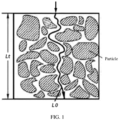
- L t can be understood as the shortest path taken by the electrolyte through the negative electrode active material layer.
- tortuosity has a significant effect on the wettability of the negative electrode plate. Limiting the tortuosity of the pore structure of the negative electrode plate can shorten the transmission path of the electrolyte in the negative electrode active material layer, and this has a significant effect in improving the low-temperature discharge performance of the battery and reducing the standing time after injection during the production process.
- the tortuosity T to adjust the pore structure of the negative electrode plate (that is, limiting the tortuosity T to T ⁇ 2.5), the wetting property of the negative electrode plate is improved.
- the tortuosity T will be affected by a particle size distribution, a compacted density and a porosity of the negative electrode plate.
- PD is the value of the compacted density of the negative electrode active material layer, and the unit is g/cm 3 .
- D v 99 represents a value of the particle size measured when the cumulative particle volume distribution of the negative electrode active material is 99% as measured by starting from small particle sizes, and the unit is ⁇ m.
- ⁇ is the porosity of the negative electrode plate.
- the tortuosity T is closely related to the compacted density PD and porosity ⁇ of the negative electrode plate, and the porosity of the negative electrode plate also affects the wettability. If the pore structure of the negative electrode active material layer is rich, the transmission path of the electrolyte will also be rich, and the infiltration of the electrolyte will be improved.
- the compacted density of the negative electrode plate and/or the D v 99 of the negative electrode active material particles will affect the degree of particle distribution density and shape, and then affect the transmission path of the electrolyte.
- the value of D v 99 of particles of the negative electrode active material in the negative electrode plate satisfies 30 ⁇ D v 99 ⁇ 60, with the unit of ⁇ m.
- the porosity ⁇ of the negative electrode active material layer in the negative electrode plate satisfies 20% ⁇ ⁇ ⁇ 40%.
- the compacted density PD of the negative electrode active material layer in the negative electrode plate is PD g/cm 3 , where 1.50 ⁇ PD ⁇ 1.75.
- the negative electrode active material layer with a high compacted density can result in flattened particles that would extend the transmission path of the electrolyte even at the presence of pores, which would be unfavorable for the flow of the electrolyte. Therefore, by limiting the compacted density PD of the negative electrode active material layer, the infiltration performance of the electrolyte can be balanced while ensuring the energy density of the electrochemical apparatus.
- the negative electrode active material includes artificial graphite, natural graphite or a combination thereof.
- the tortuosity T may also be affected by the particle morphology, sphericity, and OI value of the negative electrode plate.
- a sphericity S50 of particles of the negative electrode active material ranges from 0.70 to 0.90
- the negative electrode active material includes primary particles, secondary particles, or mixed particles composed of primary and secondary particles.
- D v 99 of particles of the negative electrode active material satisfies 0.6L 0 ⁇ D v 99 ⁇ 0.9L 0 .
- D v 99 being too large is not beneficiary to the even distribution of particles, having significant impact on the uniformity of pore structures in the negative electrode active material layer, which in turn affects the infiltration of the electrolyte. Therefore, it is limited that 0.6L 0 ⁇ D v 99 ⁇ 0.9L 0 .
- L 0 satisfies 30 ⁇ L 0 ⁇ 140, with the unit of ⁇ m.
- a bonding force between the negative electrode active material layer and the negative electrode current collector in the negative electrode plate is F ⁇ 6 N.
- Such limitation is to ensure the stability of the negative electrode plate structure, avoid detachment of the negative electrode active material layer from the negative plate current collector affecting performance of the battery, and ensure reliable bonding strength between the negative electrode active material and the current collector.
- the OI value of the negative electrode plate is influenced by the arrangement of negative electrode active material particles in the negative electrode active material layer, which may affect the tortuosity of the negative electrode active material, and thus affect the low-temperature performance of the electrochemical apparatus.
- an areal density of the negative electrode active material layer is 0.035 mg/mm 2 to 0.091 mg/mm 2 .
- the negative electrode plate further includes a binder and a dispersant.
- the binder is selected from organic latex materials, such as butadiene-styrene latex.
- the dispersant may be selected from dispersants commonly used in the field, such as polysaccharide polymer materials. In this application, the dispersant may be selected from sodium carboxymethyl cellulose.
- the negative electrode plate further includes a conductive agent, which may be selected from conductive agents commonly used in the field, such as a combination of one or more of carbon nanotubes, conductive carbon black, and graphene.
- a conductive agent which may be selected from conductive agents commonly used in the field, such as a combination of one or more of carbon nanotubes, conductive carbon black, and graphene.
- This application further provides an electronic apparatus including the electrochemical apparatus described above.
- the electrolyte includes a compound containing a sulfur-oxygen double bond; the compound containing a sulfur-oxygen double bond includes at least one of methylene methane disulfonate (MMDS), propenyl-1,3-sultone (PES), 1,3-propane disulfonic anhydride (SA), 1,3-propane sultone (PS), 2,4-butane sultone (BS), or vinyl sulfate (DTD).
- MMDS methylene methane disulfonate
- PES propenyl-1,3-sultone
- SA 1,3-propane disulfonic anhydride
- PS 1,3-propane sultone
- BS 2,4-butane sultone
- DTD vinyl sulfate
- the percentage of the compound containing a sulfur-oxygen double bond is 0.1%-5%. Further inclusion of the compound containing a sulfur-oxygen double bond in the electrolyte can further improve the low-temperature discharge performance of the electrochemical apparatus.
- the electrolyte includes lithium difluorophosphate.
- the percentage of the lithium difluorophosphate is less than 1%. If the lithium difluorophosphate content is higher than 1%, the viscosity of the electrolyte will increase, the wettability of the negative electrode plate will be affected, and the low-temperature performance of the electrochemical apparatus will be affected.
- the electrolyte transmission path can be shortened, and the wettability of the negative electrode plate can be improved.
- the use of the negative electrode plate disclosed in this application has a significant effect on reducing the standing time after injection during production and improving the low-temperature discharge performance of the battery.
- the selected negative electrode active material graphite satisfies the following description: the sphericity S50 of graphite particles ranges from 0.70 to 0.89and the particle size satisfies 0.6L 0 ⁇ D v 99 ⁇ 0.9L 0 .
- the negative electrode active material graphite, binder butadiene-styrene rubber, and thickener carboxymethyl cellulose sodium are proportioned according to a weight ratio of 97:2:1, and then thoroughly mixed in an appropriate amount of deionized water solvent to form a uniform negative electrode slurry. This slurry is applied on a current collector Cu foil, dried, and cold-pressed to obtain a negative electrode plate.
- Example 6 graphite material with a D v 99 particle size range of 30 ⁇ m-50 ⁇ m (D v 99 is 40 ⁇ m in Example 6) is selected, and the weight range of the single-sided negative electrode active material layer of the negative electrode plate is 0.035mg/mm 2 to 0.091mg/mm 2 (the weight of the single-sided negative electrode active material layer of the negative electrode plate is about 0.045mg/mm 2 in Example 6), and to ensure that the tortuosity T of the negative electrode plate is less than or equal to 2.5 and the processing performance is considered, D v 99 needs to satisfy 0.6THK ⁇ D v 99 ⁇ 0.9THK.
- the thickness range of the single-sided negative electrode active material layer after cold pressing is controlled to be 34 ⁇ m-83 ⁇ m
- the compacted PD range of the negative electrode plate is controlled to be 1.55 g/cm 3 -1.75 g/cm 3
- the cold pressing speed range of the negative electrode plate is controlled to be 10 m/min-50 m/min.
- Phosphate iron lithium is selected as the positive electrode active material, which is mixed with conductive agent acetylene black and binder polyvinylidene fluoride in a weight ratio of 96.3:2.2:1.5 in an appropriate amount of N-methylpyrrolidone solvent to form a uniform positive electrode slurry. This slurry is applied on a current collector Al foil, dried, and cold-pressed to obtain a positive electrode plate.
- ethylene carbonate (EC), propylene carbonate (PC), methyl ethyl carbonate (EMC), and diethyl carbonate (DEC) are mixed in a mass ratio of 20:20:30:30.
- 2% of fluoroethylene carbonate and 2% of 1,3-propane sultone are added, dissolved and thoroughly stirred, and lithium salt LiPF 6 is added.
- the concentration of LiPF 6 is 1 mol/L.
- the percentage of substances in the electrolyte is calculated as a mass percentage based on the weight of the electrolyte.
- PE porous polymer film is selected as the separator.
- the above negative electrode plate and positive electrode plate are rolled together with the separator, placed in an aluminum-plastic film, followed by injection of electrolyte, standing, and formation, to obtain a lithium ion secondary battery.
- Electrolytes and lithium-ion batteries of Examples 1 to 11 and Comparative Examples 1 to 2 were prepared according to the above preparation methods, and cycling performance of the batteries was tested.
- the batteries were placed in a constant temperature box of 25°C after injection, and timing was carried out from the beginning of injection at time t 1 to time t 2 when the surface of the negative electrode plate was infiltrated all through by the electrolyte.
- One battery was disassembled every hour to observe whether all positions of the entire electrode plate were infiltrated by the electrolyte, especially the corners and edges. If all were infiltrated, infiltration is considered complete.
- the infiltration time t is t 2 - t 1 .
- the compacted density PD, particle size D v 99, and porosity ⁇ of the electrode plate affect the transmission path L t of the electrolyte in the electrode plate, thereby changing the tortuosity T of the electrode plate.
- the value of L t /L 0 can be less than or equal to 2.5, which means the tortuosity T ⁇ 2.5.
- Examples 1 to 11 have the standing time after injection and low-temperature discharge performance corresponding to the tortuosity T of pores of the negative electrode plate satisfying T ⁇ 2.5, while Comparative Examples 1 and 2 have the standing time after injection and low-temperature discharge performance corresponding to the tortuosity of the negative electrode plate not satisfying the above condition.
- Example 1 Dv99 ( ⁇ m) PD (g/cm 3 ) ⁇ (%) L t ( ⁇ m) L 0 ( ⁇ m) T Standing time t after injection (h) Discharge rate at -10°C
- Example 1 34 1.50 40% 62 56 1.1 35 79.5%
- Example 2 32 1.53 37% 62 52 1.2 35 79.9%
- Example 3 34 1.55 34% 70 51 1.4 32 81.9%
- Example 4 36 1.58 33% 76 51 1.5 32 82.0%
- Example 5 39 1.55 32% 82 50 1.6 31 82.5%
- Example 6 40 1.58 30% 88 48 1.8 31 82.2%
- Example 7 41 1.60 27% 96 46 2.1 34 79.9%
- Example 8 41 1.62 25% 99 47 2.1 34 79.7%
- Example 9 40 1.65 23% 101 46 2.2 35 79.5%
- Example 10 40 1.73 21% 110 46 2.4 35 79.0%
- Example 11 43 1.75 20% 121 49 2.5 38 78.7%
- the sphericity S50 of the negative electrode active material particles is limited to 0.70 to 0.90. If S50 is too large, it is not conducive to the uniform distribution of particles, the pore pathway in the negative electrode plate is monotonous and not conducive to the multi-path flow of electrolyte. If S50 is too small, it indicates that there are more particles with corners, which will result in a significant reduction in pore structures due to the interstitial distribution of particles, which is not conducive to the infiltration and flow of electrolyte, thus affecting the low-temperature performance of the battery. Therefore, the sphericity S50 of the negative electrode active material particles is limited to 0.70 to 0.90.
- Example 6 On the basis of the Example 6, the particle sphericity S50 of the negative electrode active material particles was further limited to 0.70 to 0.90, in order to optimize the standing time after injection and low-temperature discharge performance of the batteries. Test data is shown in Table 2. Table 2 S50 Standing time t after injection (h) Discharge rate at -10°C Example 6 0.68 28 83.1% Example 12 0.70 26 84.1% Example 13 0.73 25 84.4% Example 14 0.78 24 84.5% Example 15 0.80 25 84.5% Example 16 0.85 26 84.4% Example 17 0.90 26 84.2% Example 18 0.92 28 84.0%
- Example 15 To further ensure the structural stability, low-temperature performance, and energy density of the negative electrode plate, further optimization was made based on Example 15. To ensure the stability of the negative electrode plate structure and avoid decarburization and powder shedding affecting the battery performance, and ensure that there is a reliable bonding strength between the negative electrode active material layer and the current collector, the bonding force between the active material layer and the current collector of the negative electrode plate was limited to F ⁇ 6 N.
- the OI value of the negative electrode plate has a significant impact on the low-temperature performance of the battery. If the OI value is too high, in addition to weak low-temperature discharge capacity, it may also pose safety risks such as lithium deposition. Therefore, the negative electrode plate was limited to 5 ⁇ OI value ⁇ 15.
- the negative electrode active material may be artificial graphite, natural graphite, or mixed graphite, and preferably artificial graphite is.
- primary particles, secondary particles, or composite particles can be used.
- Example 15 The bonding force F, OI value, and areal density of the negative electrode plate were further limited based on Example 15 to optimize the standing time after injection and the low-temperature discharge performance of the battery. Test data is shown in Table 3. Table 3 Bonding force F OI value Negative electrode plate areal density (g/mm 2 ) Standing time t after injection (h) Discharge rate at -10°C Example 15 5 13 0.045 25 84.5% Example 19 6 12 0.065 22 84.8% Example 20 8 13 0.068 21 84.9% Example 21 10 13 0.070 22 85.1% Example 22 9 13 0.073 20 85.2% Example 23 8 13 0.073 21 85.1% Example 24 9 15 0.075 22 85.0% Example 25 10 14 0.075 20 85.3% Example 26 8 12 0.075 21 85.1% Example 27 9 11 0.075 22 85.0% Example 28 9 13 0.078 20 84.9% Example 29 9 13 0.081 23 84.5% Example 30 9 16 0.087 24 84.3%
- this application can improve the wetting property of negative electrode active material by limiting the tortuosity of pores in the negative electrode active material to T ⁇ 2.5 in the negative electrode plate.
- the use of the negative electrode plate in this application can shorten the standing time after injection of lithium ion battery and improve the low-temperature discharge performance of the battery.
- Example 15 The electrolyte composition was further optimized based on Example 15 to improve the standing time after injection and the low-temperature discharge performance.
- Test data is given in Table 4.
- Table 4 Compound containing sulfur-oxygen double bond Lithium difluoropho sphate (%) Standing time t after injection (h) Discharge rate at -10°C Composition Percent (%)
- Example 15 PS 2 - 25 84.5%
- Example 31 PS 1 0.5 24 84.8%
- Example 32 PS+MMDS 1+0.5 - 24 85.2%
- Example 33 PS+DTD 1.5+1 - 25 85.4%
- Example 34 PS 3 0.3 25 85.1%
- Example 35 PS 2 0.6 25 85.6%
- Example 36 PS 2 0.9 26 85.8%
- Example 37 PS 2 1 27 85.1%
- Example 39 PA 0.5 0.1 25 84.3% "-" indicates no addition.
Abstract
An electrochemical apparatus and an electronic apparatus are provided. The electrochemical apparatus includes an electrolyte and a negative electrode plate. The negative electrode plate includes a negative electrode current collector and a negative electrode active material layer disposed on at least one surface of the negative electrode current collector. The negative electrode active material layer contains a negative electrode active material, and a tortuosity T of the negative electrode active material layer satisfies the following relation: 1 < T ≤ 2.5, where the tortuosity T is a ratio of a transmission path length L<sub>t</sub> of the electrolyte in pores of the negative electrode active material layer to a thickness L<sub>0</sub> of the negative electrode active material layer. By limiting the tortuosity T within the specified range, the transmission path of the electrolyte can be shortened, the wettability of the negative electrode plate can be improved, thus shortening the standing time after injection of the electrochemical apparatus during a production process while also improving the low-temperature discharge performance of the electrochemical apparatus.
Description
- This application pertains to the field of secondary battery technologies, and specifically relates to an electrochemical apparatus and an electronic apparatus containing such electrochemical apparatus.
- With the continuous expansion of the market for electrochemical apparatuses such as lithium-ion batteries, the performance requirements for batteries have been constantly increasing. Among them, the low-temperature discharge performance is an important indicator, especially for electric vehicles and electric tools. In addition, the power market imposes a high restriction on the cost of batteries, which must be kept low, and the production time cycle has a significant impact on the cost. To meet market demands, it is necessary to develop negative electrode plates with excellent electrolyte wettability and lithium-ion batteries with excellent low-temperature performance. In the existing technology, after the battery is filled with electrolyte, it is usually left for a long time at room temperature and high temperature to ensure that the electrolyte completely wets the electrode plate, which takes a long time and seriously affects the speed of battery production. In addition, this method has very limited effects in improving the rate performance of the battery, and it cannot meet the market's demand for low-temperature discharge. Therefore, it is necessary to develop new technologies to meet the requirements for cost and low-temperature discharge performance.
- To meet the above requirements for cost and low-temperature discharge performance, this application achieves it in the following aspects.
- Specifically, one aspect of this application provides an electrochemical apparatus including an electrolyte and a negative electrode plate. The negative electrode plate includes a negative electrode current collector and a negative electrode active material layer disposed on at least one surface of the negative electrode current collector. The negative electrode active material layer contains a negative electrode active material, and a tortuosity T of the negative electrode active material layer satisfies the following relation: 1 < T ≤ 2.5.
- In this application, the tortuosity T is defined as a ratio of a transmission path length Lt of the electrolyte through pores of the negative electrode active material layer to a thickness L0 of the negative electrode active material layer, that is T = Lt/L0, as shown in
FIG. 1 . Lt can be understood as the shortest path taken by the electrolyte through the negative electrode active material layer. - In this application, the inventors found that tortuosity has a significant effect on the wettability of the negative electrode plate. Limiting the tortuosity of the pore structure of the negative electrode plate can shorten the transmission path of the electrolyte in the negative electrode active material layer, and this has a significant effect in improving the low-temperature discharge performance of the battery and reducing the standing time after injection during the production process.
- In this application, by adjusting the tortuosity T to adjust the pore structure of the negative electrode plate (that is, limiting the tortuosity T to T ≤ 2.5), the wetting property of the negative electrode plate is improved. The tortuosity T will be affected by a particle size distribution, a compacted density and a porosity of the negative electrode plate. In the calculation method of the tortuosity T, the value of the transmission path Lt of the electrolyte in the negative electrode plate may be calculated according to the formula Lt = 2 × (PD × Dv99) × (1 - ε), and the unit is µm, where L0 is the value of the perpendicular distance from the surface far from the negative electrode current collector of the negative electrode active material layer to the negative electrode current collector, and the unit is µm. PD is the value of the compacted density of the negative electrode active material layer, and the unit is g/cm3. Dv99 represents a value of the particle size measured when the cumulative particle volume distribution of the negative electrode active material is 99% as measured by starting from small particle sizes, and the unit is µm. ε is the porosity of the negative electrode plate. By adjusting the compacted density PD, the Dv99 of the negative electrode active material particles and the porosity ε of the negative electrode plate, the transmission path Lt of the electrolyte in the negative electrode plate can be affected, and the tortuosity T of the negative electrode plate can be changed. In this application, the tortuosity T of the pore structure of the negative electrode plate meets certain conditions. At the same time, the tortuosity T is closely related to the compacted density PD and porosity ε of the negative electrode plate, and the porosity of the negative electrode plate also affects the wettability. If the pore structure of the negative electrode active material layer is rich, the transmission path of the electrolyte will also be rich, and the infiltration of the electrolyte will be improved. The compacted density of the negative electrode plate and/or the Dv99 of the negative electrode active material particles will affect the degree of particle distribution density and shape, and then affect the transmission path of the electrolyte.
- In an embodiment of this application, the value of Dv99 of particles of the negative electrode active material in the negative electrode plate satisfies 30 ≤ Dv99 ≤ 60, with the unit of µm.
- In an embodiment of this application, the porosity ε of the negative electrode active material layer in the negative electrode plate satisfies 20% ≤ ε ≤ 40%.
- In an embodiment of this application, the compacted density PD of the negative electrode active material layer in the negative electrode plate is PD g/cm3, where 1.50 ≤ PD ≤ 1.75. The negative electrode active material layer with a high compacted density can result in flattened particles that would extend the transmission path of the electrolyte even at the presence of pores, which would be unfavorable for the flow of the electrolyte. Therefore, by limiting the compacted density PD of the negative electrode active material layer, the infiltration performance of the electrolyte can be balanced while ensuring the energy density of the electrochemical apparatus.
- In an embodiment of this application, the negative electrode active material includes artificial graphite, natural graphite or a combination thereof.
- In this application, the tortuosity T may also be affected by the particle morphology, sphericity, and OI value of the negative electrode plate.
- In an embodiment of this application, a sphericity S50 of particles of the negative electrode active material ranges from 0.70 to 0.90,
- where S50 represents a shape factor value when a cumulative particle volume distribution of the negative electrode active material is 50%, and
- sphericity is a ratio of the circular perimeter of an equivalent projection area of a particle to an actual perimeter of the projection of the particle.
- In an embodiment of this application, the negative electrode active material includes primary particles, secondary particles, or mixed particles composed of primary and secondary particles.
- In an embodiment of this application, Dv99 of particles of the negative electrode active material satisfies 0.6L0 ≤ Dv99 ≤ 0.9L0. Dv99 being too large is not beneficiary to the even distribution of particles, having significant impact on the uniformity of pore structures in the negative electrode active material layer, which in turn affects the infiltration of the electrolyte. Therefore, it is limited that 0.6L0 ≤ Dv99 ≤ 0.9L0.
- In an embodiment of this application, L0 satisfies 30 ≤ L0 ≤ 140, with the unit of µm.
- In an embodiment of this application, a bonding force between the negative electrode active material layer and the negative electrode current collector in the negative electrode plate is F ≥ 6 N. Such limitation is to ensure the stability of the negative electrode plate structure, avoid detachment of the negative electrode active material layer from the negative plate current collector affecting performance of the battery, and ensure reliable bonding strength between the negative electrode active material and the current collector.
- In an embodiment of this application, an OI value of the negative electrode plate satisfies: 5 ≤ OI value ≤ 15, where the OI value is calculated according to the formula OI value = C004/C110; where C004 is the value of a characteristic peak area between 54.30° and 54.60°, and C110 is the value of a characteristic peak area between 77.35° and 77.50°, as tested by X-ray diffraction spectroscopy, and the OI value is equal to C004/C110. The OI value of the negative electrode plate is influenced by the arrangement of negative electrode active material particles in the negative electrode active material layer, which may affect the tortuosity of the negative electrode active material, and thus affect the low-temperature performance of the electrochemical apparatus.
- In an embodiment of this application, an areal density of the negative electrode active material layer is 0.035 mg/mm2 to 0.091 mg/mm2.
- In an embodiment of this application, the negative electrode plate further includes a binder and a dispersant. The binder is selected from organic latex materials, such as butadiene-styrene latex. The dispersant may be selected from dispersants commonly used in the field, such as polysaccharide polymer materials. In this application, the dispersant may be selected from sodium carboxymethyl cellulose.
- In an embodiment of this application, the negative electrode plate further includes a conductive agent, which may be selected from conductive agents commonly used in the field, such as a combination of one or more of carbon nanotubes, conductive carbon black, and graphene.
- This application further provides an electronic apparatus including the electrochemical apparatus described above.
- In an embodiment of this application, the electrolyte includes a compound containing a sulfur-oxygen double bond; the compound containing a sulfur-oxygen double bond includes at least one of methylene methane disulfonate (MMDS), propenyl-1,3-sultone (PES), 1,3-propane disulfonic anhydride (SA), 1,3-propane sultone (PS), 2,4-butane sultone (BS), or vinyl sulfate (DTD).
- In an embodiment of this application, based on the weight of the electrolyte, the percentage of the compound containing a sulfur-oxygen double bond is 0.1%-5%. Further inclusion of the compound containing a sulfur-oxygen double bond in the electrolyte can further improve the low-temperature discharge performance of the electrochemical apparatus.
- In an embodiment of this application, the electrolyte includes lithium difluorophosphate.
- In an embodiment of this application, based on the weight of the electrolyte, the percentage of the lithium difluorophosphate is less than 1%. If the lithium difluorophosphate content is higher than 1%, the viscosity of the electrolyte will increase, the wettability of the negative electrode plate will be affected, and the low-temperature performance of the electrochemical apparatus will be affected.
- The technical scheme provided by this application can achieve the following beneficial effects:
- By limiting the tortuosity T of the negative electrode plate within a specified range, the electrolyte transmission path can be shortened, and the wettability of the negative electrode plate can be improved. The use of the negative electrode plate disclosed in this application has a significant effect on reducing the standing time after injection during production and improving the low-temperature discharge performance of the battery.
-
-
FIG. 1 is a schematic diagram of meanings of parameters involved in the calculation of tortuosity of a negative electrode active material; -
FIG. 2 is a schematic diagram of Lt and L0 of a negative electrode plate; -
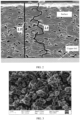
FIG. 3 shows the morphology of graphite particles in a negative electrode plate; -
FIG. 4 is a SEM image of a cross section of a negative electrode plate; and -
FIG. 5 is an enlarged SEM image of the cross section of the negative electrode plate. - To make the objectives, technical solutions, and advantages of the embodiments of this application clearer, the following clearly and completely describes the technical solutions of this application with reference to the accompanying drawings in the embodiments of this application. Apparently, the described embodiments are some but not all embodiments of this application. All other embodiments obtained by those skilled in the art based on the technical solutions of this application and the embodiments given without creative efforts shall all fall within the protection scope of this application.
- In this application, the selected negative electrode active material graphite satisfies the following description: the sphericity S50 of graphite particles ranges from 0.70 to 0.89and the particle size satisfies 0.6L0 ≤ Dv99 ≤ 0.9L0. The negative electrode active material graphite, binder butadiene-styrene rubber, and thickener carboxymethyl cellulose sodium are proportioned according to a weight ratio of 97:2:1, and then thoroughly mixed in an appropriate amount of deionized water solvent to form a uniform negative electrode slurry. This slurry is applied on a current collector Cu foil, dried, and cold-pressed to obtain a negative electrode plate. As an example, in Example 6, graphite material with a Dv99 particle size range of 30 µm-50 µm (Dv99 is 40 µm in Example 6) is selected, and the weight range of the single-sided negative electrode active material layer of the negative electrode plate is 0.035mg/mm2 to 0.091mg/mm2 (the weight of the single-sided negative electrode active material layer of the negative electrode plate is about 0.045mg/mm2 in Example 6), and to ensure that the tortuosity T of the negative electrode plate is less than or equal to 2.5 and the processing performance is considered, Dv99 needs to satisfy 0.6THK ≤ Dv99 ≤ 0.9THK. Therefore, the thickness range of the single-sided negative electrode active material layer after cold pressing is controlled to be 34 µm-83 µm, and the compacted PD range of the negative electrode plate is controlled to be 1.55 g/cm3-1.75 g/cm3, and the cold pressing speed range of the negative electrode plate is controlled to be 10 m/min-50 m/min.
- Phosphate iron lithium is selected as the positive electrode active material, which is mixed with conductive agent acetylene black and binder polyvinylidene fluoride in a weight ratio of 96.3:2.2:1.5 in an appropriate amount of N-methylpyrrolidone solvent to form a uniform positive electrode slurry. This slurry is applied on a current collector Al foil, dried, and cold-pressed to obtain a positive electrode plate.
- Preparation of electrolyte: In a dry argon atmosphere glove box, ethylene carbonate (EC), propylene carbonate (PC), methyl ethyl carbonate (EMC), and diethyl carbonate (DEC) are mixed in a mass ratio of 20:20:30:30. Then, 2% of fluoroethylene carbonate and 2% of 1,3-propane sultone are added, dissolved and thoroughly stirred, and lithium salt LiPF6 is added. After mixing evenly, the base electrolyte is obtained. The concentration of LiPF6 is 1 mol/L. The percentage of substances in the electrolyte is calculated as a mass percentage based on the weight of the electrolyte.
- PE porous polymer film is selected as the separator. The above negative electrode plate and positive electrode plate are rolled together with the separator, placed in an aluminum-plastic film, followed by injection of electrolyte, standing, and formation, to obtain a lithium ion secondary battery.
- Electrolytes and lithium-ion batteries of Examples 1 to 11 and Comparative Examples 1 to 2 were prepared according to the above preparation methods, and cycling performance of the batteries was tested.
- Low-temperature discharge rate testing procedure:
- (1) Adjust the furnace temperature to 25°C, and let the battery stand for 5 minutes;
- (2) Discharge at 0.5C to 2.5 V;
- (3) Let the battery stand for 30 minutes;
- (4) Charge at 0.2C to 3.6 V, and constant voltage charge to a current of 0.025C;
- (5) Let the battery stand for 10 minutes;
- (6) Discharge at 1.0C to a voltage of 2.5 V (reference capacity);
- (7) Let the battery stand for 10 minutes;
- (8) Charge at 0.2C to 3.6 V, and constant voltage charge to a current of 0.025C;
- (9) Let the battery stand for 10 minutes;
- (10) Adjust the furnace temperature to -10°C, and let the battery stand for 60 minutes;
- (11) Discharge at 1.0C to 2.5 V;
- (12) Charge at 0.2C to 3.6 V, and constant voltage charge to a current of 0.025C;
- (13) Let the battery stand for 10 minutes;
- (14) Discharge at 1.0C to 2.5 V (-10°C discharge capacity);
- (15) Adjust the furnace temperature to 25°C, and let the battery stand for 60 minutes; and
- (16) End the test.
- The batteries were placed in a constant temperature box of 25°C after injection, and timing was carried out from the beginning of injection at time t1 to time t2 when the surface of the negative electrode plate was infiltrated all through by the electrolyte. One battery was disassembled every hour to observe whether all positions of the entire electrode plate were infiltrated by the electrolyte, especially the corners and edges. If all were infiltrated, infiltration is considered complete. The infiltration time t is t2 - t1.
- Parameter settings and test results of the examples and comparative examples are given in Table 1.
- The compacted density PD, particle size Dv99, and porosity ε of the electrode plate affect the transmission path Lt of the electrolyte in the electrode plate, thereby changing the tortuosity T of the electrode plate. The transmission path of the electrolyte in the electrode plate is Lt = 2 × (PD × Dv99) × (1 - ε). When the compacted density PD, particle size Dv99, and porosity ε of the electrode plate are controlled to meet certain conditions, the value of Lt/L0 can be less than or equal to 2.5, which means the tortuosity T ≤ 2.5.
- In Table 1, Examples 1 to 11 have the standing time after injection and low-temperature discharge performance corresponding to the tortuosity T of pores of the negative electrode plate satisfying T ≤ 2.5, while Comparative Examples 1 and 2 have the standing time after injection and low-temperature discharge performance corresponding to the tortuosity of the negative electrode plate not satisfying the above condition.
Table 1 Dv99 (µm) PD (g/cm3) ε (%) Lt (µm) L0 (µm) T Standing time t after injection (h) Discharge rate at -10°C Example 1 34 1.50 40% 62 56 1.1 35 79.5% Example 2 32 1.53 37% 62 52 1.2 35 79.9% Example 3 34 1.55 34% 70 51 1.4 32 81.9% Example 4 36 1.58 33% 76 51 1.5 32 82.0% Example 5 39 1.55 32% 82 50 1.6 31 82.5% Example 6 40 1.58 30% 88 48 1.8 31 82.2% Example 7 41 1.60 27% 96 46 2.1 34 79.9% Example 8 41 1.62 25% 99 47 2.1 34 79.7% Example 9 40 1.65 23% 101 46 2.2 35 79.5% Example 10 40 1.73 21% 110 46 2.4 35 79.0% Example 11 43 1.75 20% 121 49 2.5 38 78.7% Comparative Example 1 45 1.75 20% 126 48 2.6 52 66.9% Comparative Example 2 46 1.76 21% 128 46 2.8 55 66.7% - From Examples 1 to 11 in Table 1, it can be found that a smaller tortuosity of the negative electrode pores is advantageous to the wetting and formation of the electrode and the low-temperature discharge performance of the battery. The tortuosity is less than or equal to 2.5 in all examples 1 to 11, and it can be found that the standing time after injection is relatively short, and the rate performance is excellent. This is because the lower tortuosity can ensure that the pore structures in the electrode plate are abundant, and the particles are not flattened, which is very beneficial to the flow of the electrolyte inside the negative electrode plate. The flow rate and path of the electrolyte are rich, which can reduce the standing time after injection and improve production efficiency. In addition, good infiltration of the electrolyte is beneficial to the low-temperature discharge performance of the battery. Low temperature will affect the flow of the electrolyte, but when the pore structures of the negative electrode are rich and evenly distributed, this effect will be small, and the battery will also show excellent rate performance at low temperature. From the comparison of comparative examples 1 and 2, it can be found that when the tortuosity T is greater than 2.5, the standing time after injection increases significantly, and the low-temperature rate performance of the battery also deteriorates significantly.
- On the basis of Example 6, further optimization is made to further control the uniform distribution of pore structures in the negative electrode plate. The sphericity S50 of the negative electrode active material particles is limited to 0.70 to 0.90. If S50 is too large, it is not conducive to the uniform distribution of particles, the pore pathway in the negative electrode plate is monotonous and not conducive to the multi-path flow of electrolyte. If S50 is too small, it indicates that there are more particles with corners, which will result in a significant reduction in pore structures due to the interstitial distribution of particles, which is not conducive to the infiltration and flow of electrolyte, thus affecting the low-temperature performance of the battery. Therefore, the sphericity S50 of the negative electrode active material particles is limited to 0.70 to 0.90.
- On the basis of the Example 6, the particle sphericity S50 of the negative electrode active material particles was further limited to 0.70 to 0.90, in order to optimize the standing time after injection and low-temperature discharge performance of the batteries. Test data is shown in Table 2.
Table 2 S50 Standing time t after injection (h) Discharge rate at -10°C Example 6 0.68 28 83.1% Example 12 0.70 26 84.1% Example 13 0.73 25 84.4% Example 14 0.78 24 84.5% Example 15 0.80 25 84.5% Example 16 0.85 26 84.4% Example 17 0.90 26 84.2% Example 18 0.92 28 84.0% - It can be found from Table 2 that when the sphericity S50 of the material particles ranges from 0.70 to 0.90, both the standing time after injection and the low-temperature discharge performance are relatively excellent.
- To further ensure the structural stability, low-temperature performance, and energy density of the negative electrode plate, further optimization was made based on Example 15. To ensure the stability of the negative electrode plate structure and avoid decarburization and powder shedding affecting the battery performance, and ensure that there is a reliable bonding strength between the negative electrode active material layer and the current collector, the bonding force between the active material layer and the current collector of the negative electrode plate was limited to F ≥ 6 N. The OI value of the negative electrode plate has a significant impact on the low-temperature performance of the battery. If the OI value is too high, in addition to weak low-temperature discharge capacity, it may also pose safety risks such as lithium deposition. Therefore, the negative electrode plate was limited to 5 ≤ OI value ≤ 15. To ensure the low-temperature performance and energy density of the battery, the areal density range of the negative electrode plate was limited to 0.035 mg/mm2-0.091 mg/mm2. The negative electrode active material may be artificial graphite, natural graphite, or mixed graphite, and preferably artificial graphite is. For the structure of graphite, primary particles, secondary particles, or composite particles can be used.
- The bonding force F, OI value, and areal density of the negative electrode plate were further limited based on Example 15 to optimize the standing time after injection and the low-temperature discharge performance of the battery. Test data is shown in Table 3.
Table 3 Bonding force F OI value Negative electrode plate areal density (g/mm2) Standing time t after injection (h) Discharge rate at -10°C Example 15 5 13 0.045 25 84.5% Example 19 6 12 0.065 22 84.8% Example 20 8 13 0.068 21 84.9% Example 21 10 13 0.070 22 85.1% Example 22 9 13 0.073 20 85.2% Example 23 8 13 0.073 21 85.1% Example 24 9 15 0.075 22 85.0% Example 25 10 14 0.075 20 85.3% Example 26 8 12 0.075 21 85.1% Example 27 9 11 0.075 22 85.0% Example 28 9 13 0.078 20 84.9% Example 29 9 13 0.081 23 84.5% Example 30 9 16 0.087 24 84.3% - It can be found from Table 3 that the improvement of bonding force is beneficial for low-temperature discharge. The larger negative electrode OI value or areal density of the negative electrode active material layer will cause slight loss to the low-temperature performance. Therefore, limiting the bonding force F, OI value, and areal density of the negative electrode plate to within specified ranges can optimize the standing time after injection and low-temperature discharge performance of the battery.
- In conclusion, this application can improve the wetting property of negative electrode active material by limiting the tortuosity of pores in the negative electrode active material to T ≤ 2.5 in the negative electrode plate. The use of the negative electrode plate in this application can shorten the standing time after injection of lithium ion battery and improve the low-temperature discharge performance of the battery.
- The electrolyte composition was further optimized based on Example 15 to improve the standing time after injection and the low-temperature discharge performance. Test data is given in Table 4.
Table 4 Compound containing sulfur-oxygen double bond Lithium difluoropho sphate (%) Standing time t after injection (h) Discharge rate at -10°C Composition Percent (%) Example 15 PS 2 - 25 84.5% Example 31 PS 1 0.5 24 84.8% Example 32 PS+ MMDS 1+0.5 - 24 85.2% Example 33 PS+DTD 1.5+1 - 25 85.4% Example 34 PS 3 0.3 25 85.1% Example 35 PS 2 0.6 25 85.6% Example 36 PS 2 0.9 26 85.8% Example 37 PS 2 1 27 85.1% Example 38 PS+DTD 3+2 0.1 24 85.3% Example 39 PA 0.5 0.1 25 84.3% "-" indicates no addition. - Through Table 4, it can be found that adjusting the composition of the electrolyte appropriately can further improve the wettability of the negative electrode plate while also improving the low-temperature discharge rate of the battery.
Claims (11)
- An electrochemical apparatus comprising an electrolyte and a negative electrode plate, wherein the negative electrode plate comprises a negative electrode current collector and a negative electrode active material layer disposed on at least one surface of the negative electrode current collector, and the negative electrode active material layer contains a negative electrode active material, wherein a tortuosity T of the negative electrode active material layer satisfies the following relation: 1 < T ≤ 2.5;
wherein the tortuosity T is a ratio of a transmission path length Lt of the electrolyte through pores of the negative electrode active material layer to a thickness L0 of the negative electrode active material layer. - The electrochemical apparatus according to claim 1, wherein a porosity ε of the negative electrode active material layer satisfies: 20% ≤ ε ≤ 40%.
- The electrochemical apparatus according to claim 1, wherein a compacted density PD g/cm3 of the negative electrode active material layer satisfies the following relation: 1.50 ≤ PD ≤ 1.75.
- The electrochemical apparatus according to claim 1, wherein a sphericity S50 of particles of the negative electrode active material ranges from 0.70 to 0.90;wherein S50 represents a shape factor value when a cumulative particle volume distribution of the negative electrode active material is 50%; andthe sphericity is a ratio of a circular perimeter of an equivalent projected area of a particle to an actual perimeter of a projection of the particle.
- The electrochemical apparatus according to claim 1, wherein Dv99 of particles of the negative electrode active material and L0 satisfies: 0.6L0 ≤ Dv99 ≤ 0.9L0.
- The electrochemical apparatus according to claim 1, wherein a bonding force F between the negative electrode active material layer and the negative electrode current collector satisfies: F ≥ 6 N.
- The electrochemical apparatus according to claim 1, wherein an OI value of the negative electrode plate satisfies: 5 ≤ OI value ≤ 15, wherein the OI value is calculated according to the formula: OI value = C004/C110;
wherein C004 is a value of a characteristic peak area of the negative electrode plate at 54.30° to 54.60°, and C110 is a value of a characteristic peak area around 77.35° to 77.50°, as tested by X-ray diffraction spectroscopy. - The electrochemical apparatus according to claim 1, wherein an areal density of the negative electrode active material layer is 0.035 mg/mm2 to 0.091 mg/mm2.
- The electrochemical apparatus according to claim 1, wherein the electrolyte comprises a compound containing a sulfur-oxygen double bond; and
the compound containing a sulfur-oxygen double bond comprises at least one of methylene methane disulfonate, propenyl-1,3-sultone, 1,3-propane disulfonic anhydride, 1,3-propane sultone, 2,4-butane sultone, or vinyl sulfate, and a percentage of the compound containing a sulfur-oxygen double bond is 0.1%-5% based on a weight of the electrolyte. - The electrochemical apparatus according to claim 1, wherein the electrolyte comprises lithium difluorophosphate, and a percentage of lithium difluorophosphate is below 1% based on a weight of the electrolyte.
- An electronic apparatus comprising the electrochemical apparatus according to any one of claims 1 to 10.
Applications Claiming Priority (1)
| Application Number | Priority Date | Filing Date | Title |
|---|---|---|---|
| PCT/CN2020/132918 WO2022110204A1 (en) | 2020-11-30 | 2020-11-30 | Electrochemical device and electronic device |
Publications (1)
| Publication Number | Publication Date |
|---|---|
| EP4254547A1 true EP4254547A1 (en) | 2023-10-04 |
Family
ID=77712089
Family Applications (1)
| Application Number | Title | Priority Date | Filing Date |
|---|---|---|---|
| EP20963092.0A Pending EP4254547A1 (en) | 2020-11-30 | 2020-11-30 | Electrochemical device and electronic device |
Country Status (4)
| Country | Link |
|---|---|
| US (1) | US20230299277A1 (en) |
| EP (1) | EP4254547A1 (en) |
| CN (1) | CN113424348B (en) |
| WO (1) | WO2022110204A1 (en) |
Families Citing this family (3)
| Publication number | Priority date | Publication date | Assignee | Title |
|---|---|---|---|---|
| CN115832166B (en) * | 2021-09-23 | 2024-01-12 | 宁德时代新能源科技股份有限公司 | Positive electrode sheet, secondary battery, battery module, battery pack, and power consumption device |
| CN113964375A (en) * | 2021-10-25 | 2022-01-21 | 东莞新能源科技有限公司 | Electrochemical device and electronic device |
| KR20240032150A (en) * | 2022-06-01 | 2024-03-08 | 컨템포러리 엠퍼렉스 테크놀로지 씨오., 리미티드 | Secondary batteries, battery modules, battery packs, and electrical devices |
Family Cites Families (14)
| Publication number | Priority date | Publication date | Assignee | Title |
|---|---|---|---|---|
| US8323815B2 (en) * | 2006-06-16 | 2012-12-04 | Porous Power Technology, LLC | Optimized microporous structure of electrochemical cells |
| JP7111468B2 (en) * | 2014-11-03 | 2022-08-02 | 24エム・テクノロジーズ・インコーポレイテッド | Prelithiation of electrode materials in semi-solid electrodes |
| CN108199005B (en) * | 2018-01-03 | 2020-06-23 | 浙江衡远新能源科技有限公司 | Rolling method and equipment for battery pole piece |
| EP3753034A1 (en) * | 2018-02-13 | 2020-12-23 | Fisker Inc. | Low tortuosity electrodes and electrolytes, and methods of their manufacture |
| US10826111B2 (en) * | 2018-04-24 | 2020-11-03 | Gotion, Inc. | Pre-cell formation electrodes and lithium ion batteries |
| CN110660955B (en) * | 2018-06-29 | 2021-11-23 | 宁德时代新能源科技股份有限公司 | Negative pole piece, preparation method thereof and electrochemical device |
| KR102590425B1 (en) * | 2018-10-24 | 2023-10-18 | 주식회사 엘지에너지솔루션 | Anode Comprising Graphite and Silicon-based material having the Different Diameter and Lithium Secondary Battery Comprising the Same |
| CN110265625B (en) * | 2018-11-12 | 2020-12-04 | 宁德时代新能源科技股份有限公司 | Negative pole piece and lithium ion secondary battery |
| CN112563491B (en) * | 2019-03-21 | 2023-10-24 | 宁德新能源科技有限公司 | Negative electrode material, negative electrode comprising same, and electrochemical device |
| CN110957470B (en) * | 2019-12-06 | 2021-05-18 | 华中科技大学 | Preparation method of lithium ion battery pole piece with vertical pore channel structure and product |
| CN111312985A (en) * | 2020-02-27 | 2020-06-19 | 湖北亿纬动力有限公司 | Pole piece with porosity gradient distribution as well as preparation method and application thereof |
| CN113497230A (en) * | 2020-03-20 | 2021-10-12 | 宁德新能源科技有限公司 | Negative electrode active material, and electrochemical device and electronic device using same |
| CN111933892B (en) * | 2020-07-27 | 2022-03-18 | 珠海冠宇电池股份有限公司 | Negative plate, preparation method thereof and lithium ion secondary battery comprising negative plate |
| CN111916670B (en) * | 2020-09-23 | 2022-03-15 | 珠海冠宇电池股份有限公司 | Negative plate and application thereof |
-
2020
- 2020-11-30 EP EP20963092.0A patent/EP4254547A1/en active Pending
- 2020-11-30 WO PCT/CN2020/132918 patent/WO2022110204A1/en unknown
- 2020-11-30 CN CN202080010017.9A patent/CN113424348B/en active Active
-
2023
- 2023-05-26 US US18/324,419 patent/US20230299277A1/en active Pending
Also Published As
| Publication number | Publication date |
|---|---|
| CN113424348A (en) | 2021-09-21 |
| US20230299277A1 (en) | 2023-09-21 |
| CN113424348B (en) | 2022-12-27 |
| WO2022110204A1 (en) | 2022-06-02 |
Similar Documents
| Publication | Publication Date | Title |
|---|---|---|
| EP4254547A1 (en) | Electrochemical device and electronic device | |
| CN105895879B (en) | Fluorine-doped carbon-coated positive electrode composite material and preparation method and application thereof | |
| CN109119592B (en) | Lithium titanate negative electrode piece, preparation method and lithium titanate battery | |
| CN112133896B (en) | High-capacity graphite-silicon oxide composite material and preparation method and application thereof | |
| CN108075125A (en) | A kind of graphene/silicon anode composite and its preparation method and application | |
| CN111689500A (en) | Preparation method of low-expansibility SiO/graphite composite electrode material | |
| WO2023184871A1 (en) | Composite positive electrode material and preparation method therefor and application thereof | |
| CN112635773A (en) | Positive pole piece for primary battery and primary battery | |
| CN113178620A (en) | Preparation method of lithium ion battery with high-power charging performance | |
| CN113594459B (en) | Composite negative electrode material with multilayer structure and preparation method and application thereof | |
| CN116093417A (en) | Sodium ion battery and energy storage device | |
| CN109546109A (en) | A kind of high-temperature stable lithium battery anode | |
| CN109309228B (en) | Positive electrode active material, preparation method, positive electrode and high-specific-energy power battery | |
| CN115036458B (en) | Lithium ion battery | |
| WO2022140978A1 (en) | Negative electrode plate, electrochemical device comprising negative electrode plate, and electronic device | |
| JP7206379B2 (en) | Negative electrode material and electrochemical device and electronic equipment containing the same | |
| CN115207304A (en) | Graphite cathode composite material, preparation method thereof and lithium ion battery | |
| CN114188541A (en) | Positive electrode plate of lithium ion battery and preparation method thereof | |
| CN109962232B (en) | Positive electrode active material, preparation method, positive electrode and battery | |
| CN111170294A (en) | Preparation method of low-cost lithium iron phosphate composite material | |
| CN112670449A (en) | Silicon-carbon composite pole piece, preparation method and application thereof | |
| CN110890595A (en) | Preparation method of ultralow-temperature lithium ion battery for electronic cigarette | |
| CN114220943B (en) | Sandwich structure pole piece and production system device thereof | |
| CN114944488B (en) | Preparation method of coated positive electrode material, product and application thereof | |
| CN115893400B (en) | Preparation method of negative electrode material for long-cycle lithium ion battery |
Legal Events
| Date | Code | Title | Description |
|---|---|---|---|
| STAA | Information on the status of an ep patent application or granted ep patent |
Free format text: STATUS: THE INTERNATIONAL PUBLICATION HAS BEEN MADE |
|
| PUAI | Public reference made under article 153(3) epc to a published international application that has entered the european phase |
Free format text: ORIGINAL CODE: 0009012 |
|
| STAA | Information on the status of an ep patent application or granted ep patent |
Free format text: STATUS: REQUEST FOR EXAMINATION WAS MADE |
|
| 17P | Request for examination filed |
Effective date: 20230629 |
|
| AK | Designated contracting states |
Kind code of ref document: A1 Designated state(s): AL AT BE BG CH CY CZ DE DK EE ES FI FR GB GR HR HU IE IS IT LI LT LU LV MC MK MT NL NO PL PT RO RS SE SI SK SM TR |
|
| DAV | Request for validation of the european patent (deleted) | ||
| DAX | Request for extension of the european patent (deleted) |