EP4254531A1 - Electrode driving roller and notching apparatus comprising same - Google Patents
Electrode driving roller and notching apparatus comprising same Download PDFInfo
- Publication number
- EP4254531A1 EP4254531A1 EP22865033.9A EP22865033A EP4254531A1 EP 4254531 A1 EP4254531 A1 EP 4254531A1 EP 22865033 A EP22865033 A EP 22865033A EP 4254531 A1 EP4254531 A1 EP 4254531A1
- Authority
- EP
- European Patent Office
- Prior art keywords
- electrode
- running roller
- tapered section
- electrode sheet
- coating portion
- Prior art date
- Legal status (The legal status is an assumption and is not a legal conclusion. Google has not performed a legal analysis and makes no representation as to the accuracy of the status listed.)
- Granted
Links
Images

Classifications
-
- B—PERFORMING OPERATIONS; TRANSPORTING
- B65—CONVEYING; PACKING; STORING; HANDLING THIN OR FILAMENTARY MATERIAL
- B65H—HANDLING THIN OR FILAMENTARY MATERIAL, e.g. SHEETS, WEBS, CABLES
- B65H27/00—Special constructions, e.g. surface features, of feed or guide rollers for webs
-
- H—ELECTRICITY
- H01—ELECTRIC ELEMENTS
- H01M—PROCESSES OR MEANS, e.g. BATTERIES, FOR THE DIRECT CONVERSION OF CHEMICAL ENERGY INTO ELECTRICAL ENERGY
- H01M10/00—Secondary cells; Manufacture thereof
- H01M10/04—Construction or manufacture in general
-
- H—ELECTRICITY
- H01—ELECTRIC ELEMENTS
- H01M—PROCESSES OR MEANS, e.g. BATTERIES, FOR THE DIRECT CONVERSION OF CHEMICAL ENERGY INTO ELECTRICAL ENERGY
- H01M10/00—Secondary cells; Manufacture thereof
- H01M10/04—Construction or manufacture in general
- H01M10/0404—Machines for assembling batteries
-
- H—ELECTRICITY
- H01—ELECTRIC ELEMENTS
- H01M—PROCESSES OR MEANS, e.g. BATTERIES, FOR THE DIRECT CONVERSION OF CHEMICAL ENERGY INTO ELECTRICAL ENERGY
- H01M4/00—Electrodes
- H01M4/02—Electrodes composed of, or comprising, active material
- H01M4/04—Processes of manufacture in general
- H01M4/0402—Methods of deposition of the material
- H01M4/0404—Methods of deposition of the material by coating on electrode collectors
-
- H—ELECTRICITY
- H01—ELECTRIC ELEMENTS
- H01M—PROCESSES OR MEANS, e.g. BATTERIES, FOR THE DIRECT CONVERSION OF CHEMICAL ENERGY INTO ELECTRICAL ENERGY
- H01M4/00—Electrodes
- H01M4/02—Electrodes composed of, or comprising, active material
- H01M4/04—Processes of manufacture in general
- H01M4/043—Processes of manufacture in general involving compressing or compaction
- H01M4/0435—Rolling or calendering
-
- H—ELECTRICITY
- H01—ELECTRIC ELEMENTS
- H01M—PROCESSES OR MEANS, e.g. BATTERIES, FOR THE DIRECT CONVERSION OF CHEMICAL ENERGY INTO ELECTRICAL ENERGY
- H01M50/00—Constructional details or processes of manufacture of the non-active parts of electrochemical cells other than fuel cells, e.g. hybrid cells
- H01M50/50—Current conducting connections for cells or batteries
- H01M50/531—Electrode connections inside a battery casing
-
- B—PERFORMING OPERATIONS; TRANSPORTING
- B65—CONVEYING; PACKING; STORING; HANDLING THIN OR FILAMENTARY MATERIAL
- B65H—HANDLING THIN OR FILAMENTARY MATERIAL, e.g. SHEETS, WEBS, CABLES
- B65H2404/00—Parts for transporting or guiding the handled material
- B65H2404/10—Rollers
- B65H2404/13—Details of longitudinal profile
- B65H2404/131—Details of longitudinal profile shape
- B65H2404/1312—Details of longitudinal profile shape tapered shape
-
- B—PERFORMING OPERATIONS; TRANSPORTING
- B65—CONVEYING; PACKING; STORING; HANDLING THIN OR FILAMENTARY MATERIAL
- B65H—HANDLING THIN OR FILAMENTARY MATERIAL, e.g. SHEETS, WEBS, CABLES
- B65H2404/00—Parts for transporting or guiding the handled material
- B65H2404/10—Rollers
- B65H2404/13—Details of longitudinal profile
- B65H2404/131—Details of longitudinal profile shape
- B65H2404/1317—End profile
- B65H2404/13171—End profile tapered
-
- B—PERFORMING OPERATIONS; TRANSPORTING
- B65—CONVEYING; PACKING; STORING; HANDLING THIN OR FILAMENTARY MATERIAL
- B65H—HANDLING THIN OR FILAMENTARY MATERIAL, e.g. SHEETS, WEBS, CABLES
- B65H2511/00—Dimensions; Position; Numbers; Identification; Occurrences
- B65H2511/10—Size; Dimensions
- B65H2511/11—Length
-
- B—PERFORMING OPERATIONS; TRANSPORTING
- B65—CONVEYING; PACKING; STORING; HANDLING THIN OR FILAMENTARY MATERIAL
- B65H—HANDLING THIN OR FILAMENTARY MATERIAL, e.g. SHEETS, WEBS, CABLES
- B65H2601/00—Problem to be solved or advantage achieved
- B65H2601/20—Avoiding or preventing undesirable effects
- B65H2601/25—Damages to handled material
-
- B—PERFORMING OPERATIONS; TRANSPORTING
- B65—CONVEYING; PACKING; STORING; HANDLING THIN OR FILAMENTARY MATERIAL
- B65H—HANDLING THIN OR FILAMENTARY MATERIAL, e.g. SHEETS, WEBS, CABLES
- B65H2701/00—Handled material; Storage means
- B65H2701/10—Handled articles or webs
- B65H2701/17—Nature of material
- B65H2701/172—Composite material
-
- B—PERFORMING OPERATIONS; TRANSPORTING
- B65—CONVEYING; PACKING; STORING; HANDLING THIN OR FILAMENTARY MATERIAL
- B65H—HANDLING THIN OR FILAMENTARY MATERIAL, e.g. SHEETS, WEBS, CABLES
- B65H2701/00—Handled material; Storage means
- B65H2701/10—Handled articles or webs
- B65H2701/17—Nature of material
- B65H2701/173—Metal
-
- B—PERFORMING OPERATIONS; TRANSPORTING
- B65—CONVEYING; PACKING; STORING; HANDLING THIN OR FILAMENTARY MATERIAL
- B65H—HANDLING THIN OR FILAMENTARY MATERIAL, e.g. SHEETS, WEBS, CABLES
- B65H2701/00—Handled material; Storage means
- B65H2701/10—Handled articles or webs
- B65H2701/19—Specific article or web
-
- B—PERFORMING OPERATIONS; TRANSPORTING
- B65—CONVEYING; PACKING; STORING; HANDLING THIN OR FILAMENTARY MATERIAL
- B65H—HANDLING THIN OR FILAMENTARY MATERIAL, e.g. SHEETS, WEBS, CABLES
- B65H2801/00—Application field
- B65H2801/72—Fuel cell manufacture
-
- Y—GENERAL TAGGING OF NEW TECHNOLOGICAL DEVELOPMENTS; GENERAL TAGGING OF CROSS-SECTIONAL TECHNOLOGIES SPANNING OVER SEVERAL SECTIONS OF THE IPC; TECHNICAL SUBJECTS COVERED BY FORMER USPC CROSS-REFERENCE ART COLLECTIONS [XRACs] AND DIGESTS
- Y02—TECHNOLOGIES OR APPLICATIONS FOR MITIGATION OR ADAPTATION AGAINST CLIMATE CHANGE
- Y02E—REDUCTION OF GREENHOUSE GAS [GHG] EMISSIONS, RELATED TO ENERGY GENERATION, TRANSMISSION OR DISTRIBUTION
- Y02E60/00—Enabling technologies; Technologies with a potential or indirect contribution to GHG emissions mitigation
- Y02E60/10—Energy storage using batteries
-
- Y—GENERAL TAGGING OF NEW TECHNOLOGICAL DEVELOPMENTS; GENERAL TAGGING OF CROSS-SECTIONAL TECHNOLOGIES SPANNING OVER SEVERAL SECTIONS OF THE IPC; TECHNICAL SUBJECTS COVERED BY FORMER USPC CROSS-REFERENCE ART COLLECTIONS [XRACs] AND DIGESTS
- Y02—TECHNOLOGIES OR APPLICATIONS FOR MITIGATION OR ADAPTATION AGAINST CLIMATE CHANGE
- Y02P—CLIMATE CHANGE MITIGATION TECHNOLOGIES IN THE PRODUCTION OR PROCESSING OF GOODS
- Y02P70/00—Climate change mitigation technologies in the production process for final industrial or consumer products
- Y02P70/50—Manufacturing or production processes characterised by the final manufactured product
Definitions
- the present invention relates to an electrode running roller and a notching device comprising the same.
- a rechargeable secondary battery is widely used as energy sources for various mobile devices.
- the secondary battery is attracting attention as an energy source for an electric vehicle, a hybrid vehicle and the like, which are proposed as a solution to air pollution caused by existing a gasoline vehicle and a diesel vehicle.
- the secondary battery is classified into a coin-shaped battery, a cylindrical battery, a prismatic battery, and a pouch-shaped battery according to the shape of the battery case in which the electrode assembly is incorporated.
- the electrode assembly incorporated in the battery case is classified into a jelly-roll type in which a separation membrane is interposed and wound up between an anode and a cathode, a stack type in which a plurality of unit cells with the separation membrane interposed between the anode and the cathode are stacked, and a stack/folding type in which the unit cells are wound with a separation film.
- Such a secondary battery can be manufactured by coating an electrode mixture, which is a mixture of an electrode active material, a conductive material, a binder, etc., on an electrode current collector and then drying it to manufacture an electrode, laminating the manufactured electrode together with the separation membrane to form an electrode assembly, and then embedding and sealing in a battery case together with an electrolyte.
- the electrode assembly is classified into a stack type, a folding type, a stack-folding type, etc. depending on the manufacturing methods.
- the unit assemblies In the case of a stack type or stack-folding type electrode assembly, the unit assemblies have a structure in which an anode and a cathode are sequentially laminated with a separation film interposed therebetween. In order to manufacture such an electrode assembly, it is first necessary to manufacture the anode and the cathode having electrode tabs formed thereon.
- a notching process is required to form the electrode tabs on a continuous electrode sheet coated with an electrode active material on one or both sides thereof.
- the notching process generally consists of a process of placing an electrode sheet on a die and punching out a part of the electrode sheet using a press.
- the electrode sheets are conveyed by running rollers that run in synchronism with the operation of the press, and are sequentially punched to form electrode tabs.
- the surface of the electrode sheet is made up of a coating portion coated with an electrode active material, and a non-coating portion coated with no electrode active material, and the running roller is formed in a cylindrical shape.
- the electrode sheet moves in close contact with an outer peripheral surface of the running roller.
- An object of the present invention is to provide an electrode running roller that can solve the problem of occurrence of breakage at the boundary between a coating portion and a non-coating portion of an electrode sheet, when the electrode sheet is conveyed by the electrode running roller.
- Another object of the present invention is to provide a notching device comprising the electrode running roller.
- the present invention provides an electrode running roller which causes an electrode sheet including a current collector is coated with an electrode active material to run,
- a ratio of the length of the cylindrical section to a length of the tapered section may be 4:1 to 1:1.
- the tapered section may have a truncated conical form.
- the tapered section may form an outer peripheral surface inclined at an angle of 0.2 to 0.5 degrees toward a central axis on the basis of an outer peripheral surface of the cylindrical section.
- the electrode sheet may have a coating portion coated with an electrode active material, and a non-coating portion not coated with the electrode active material, and the electrode running roller may be disposed such that the non-coating portion is positioned in the tapered section.
- the electrode running roller may be disposed such that the coating portion of the electrode sheet is positioned at a boundary between the cylindrical section and the tapered section.
- a portion of the electrode sheet, except the non-coating portion, may be in contact with the outer peripheral surface of the cylindrical section.
- the present invention provides a notching device for forming an electrode tab on a continuous electrode sheet in which an electrode active material is coated on one side or both sides of a current collector in a manufacturing process of a battery cell.
- the notching device comprises:
- the electrode running roller of the present invention includes a tapered section extending from one side end of a cylindrical section, and by disposing the non-coating portion of the electrode sheet in the tapered section, it is possible to reduce breakages that occur at the boundary between the coating portion and the non-coating portion of the electrode sheet when the electrode is running.
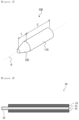
- FIG. 1 is a perspective view showing an electrode running roller according to an embodiment of the present invention.
- an electrode running roller 100 is an electrode running roller 100 which causes an electrode sheet 10 in which a current collector 11 is coated with an electrode active material to run, and the electrode running roller 100 includes a cylindrical section 110 and a tapered section 120 extending from one end portion of the cylindrical section 110.
- the tapered section 120 is configured such that the outer diameter gradually decreases toward the distal end portion of the tapered section 120.
- the electrode sheet 10 may include a coating portion 12 coated with an electrode active material on one side or both sides of a current collector 11 and a non-coating portion 13 not coated with the electrode active material.
- the coating portion 12 of the electrode sheet 10 may be continuously coated with the electrode active material along the running direction of the electrode running roller 100. Further, the non-coating portion 13 may not be coated with the electrode active material on the side portion in the running direction of the electrode running roller 100.
- the non-coating portion 13 of the electrode sheet 10 may be disposed to be positioned in the tapered section 120 of the electrode running roller 100.
- FIG. 3 is a perspective view showing an electrode running roller according to a conventional embodiment.
- the conventional electrode running roller 100 includes a cylindrical section 110 and a variable section 130 having a smaller diameter than the cylindrical section 110 so that a step S1 is formed on the outer peripheral surface of the cylindrical section.
- the coating portion 12 of the electrode sheet 10 can be disposed at a position where it is in contact with the outer peripheral surface of the cylindrical section 110, and the non-coating portion 13 can be disposed to be positioned in the variable section 130 of the electrode running roller 100.
- the boundary between the coating portion 12 and the non-coating portion 13 can be in contact with the outer peripheral surface of the cylindrical section 110. Therefore, when the electrode running roller 100 runs, because the cylindrical section 110 directly abuts on the boundary between the coating portion 12 and the non-coating portion 13 and acts as an external force, the effect of blocking and dispersing stress is minimal. Therefore, when the electrode sheet 10 is conveyed by the electrode running roller 100, there is a problem that the electrode sheet 10 is broken.
- the present invention attempts to solve the above problem by providing the electrode running roller 100 comprising the tapered section 120 extending from one side end portion of the cylindrical section 110.
- the electrode running roller 100 which is an embodiment of the present invention, will be described in more detail with reference to FIG. 1 .
- the ratio of the length (L) of the cylindrical section and the length (C) of the tapered section may be between 4:1 and 1:1, preferably between 3:2 and 7:3. Since it is possible to reduce the stress generated at the boundary between the coating portion 12 and the non-coating portion 13 of the electrode sheet 10. Within the above ratio range, occurrence of the breakage of the electrode sheet 10 can be prevented. Specifically, if the maximum effective stress generated at the boundary between the coating portion 12 and the non-coating portion 13 of the electrode sheet 10 is 50 MPa or more, the electrode sheet 10 may break.
- the ratio of the length L of the cylindrical section to the length C of the tapered section is 4:1 to 1:1, the maximum effective stress generated at the boundary between the coating portion 12 and the non-coating portion 13 of the electrode sheet 10 is less than 50 MPa, and it is possible to solve the problem of breakage of the electrode sheet 10 accordingly. If the ratio of the length L of the cylindrical section to the length C of the tapered section is out of the range of 4:1 to 1:1, the stress is generated at 50 MPa or more, and the effect of improving the breakage problem generated in the electrode sheet 10 is low.
- the tapered section 120 may have a truncated conical shape, and may form an outer peripheral surface that is inclined at an angle of 0.2 to 0.5 degrees, preferably, an angle of 0.25 to 0.35 degrees, toward the central axis P. In the above angle range, the contact between the non-coating portion 13 of the electrode sheet 10 and the tapered section 120 can be minimized, and the breakage of the electrode sheet 10 can be prevented.
- FIG. 4 is a perspective view showing a state in which electrode running rollers according to an embodiment of the present invention are applied.
- the non-coating portion 13 of the electrode sheet 10 is positioned in the tapered section 120, and in the electrode running roller 100, the coating portion 12 of the electrode sheet 10 can be disposed at the boundary between the cylindrical section 110 and the tapered section 120.
- the portion except for the non-coating portion 13 can be in contact with the outer peripheral surface of the cylindrical section 110.
- the electrode running roller 100 configured as described above, by forming the tapered section 120 at one end portion of the cylindrical section 110 in which the electrode sheet 10 is in close contact with the outer peripheral surface when the electrode sheet 10 runs, since the portion of the electrode sheet 10 except for the non-coating portion 13 not coated with the electrode active material can be brought into close contact with the outer peripheral surface of the cylindrical section 110, it is possible to prevent breakage that occurs in the boundary between the non-coating portion 13 and the coating portion 12.
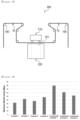
- FIG. 5 is a front view showing a notching device comprising the electrode running rollers according to an embodiment of the present invention.
- a notching device 200 according to an embodiment of the present invention comprises electrode running rollers 100 which causes the electrode sheet 10 to run.
- the notching device 200 is made up of a press 210, a die 220 and an electrode running roller 100, and the continuous electrode sheet 10, in which the electrode active material is applied to one or both sides of a current collector, runs on the electrode running roller 100 of the notching device 200.
- the press 210 punches the electrode sheet 10 at regular intervals so that electrode tabs are formed on the electrode sheet 10, and the electrode running roller 100 functions to convey the electrode sheet 10 by the press 210 in synchronization with the operation of the press 210.
- the die 220 is formed with an opening 221 having a shape corresponding to the press 210 so that scrap punched by the press 210 can be discharged.
- the electrode running roller 100 is according to an embodiment of the present invention described above.
- Example 1 Example 2
- Example 3 Example 4 Compara tive Example 1 Compara tive Example 2 Compara tive Example 3
- Maximum effective stress (MPa) 32.4 42.7 37.2 47.6 79.6 61.4 52.2
- the electrode sheet may break.
- the electrode running rollers of Examples 1 to 4 comprising the tapered section extending from one end portion of the cylindrical section showed a result that a maximum effective stress was less than 50 MPa. From this, it can be seen that the electrode running roller of the present invention can prevent breakage occurring in the electrode sheet and stably convey the electrode sheet.
- Comparative Example 1 is an electrode running roller comprising a variable section instead of a tapered section at one end portion of a cylindrical section, and shows that result that the maximum effective stress was 50 MPa or more due to the step between the cylindrical section and the tapered section. From this, it can be predicted that the electrode running roller of Comparative Example 1 cannot prevent breakage when conveying the electrode sheet.
Landscapes
- Chemical & Material Sciences (AREA)
- Chemical Kinetics & Catalysis (AREA)
- Electrochemistry (AREA)
- General Chemical & Material Sciences (AREA)
- Engineering & Computer Science (AREA)
- Manufacturing & Machinery (AREA)
- Battery Electrode And Active Subsutance (AREA)
Abstract
Description
- The present application claims the benefit of priority based on
Korean Patent Application Nos. 10-2021-0115349 filed August 31, 2021 10-2022-0109300 filed on August 30, 2022 - The present invention relates to an electrode running roller and a notching device comprising the same.
- With increasing technological development and demand for mobile devices, a rechargeable secondary battery is widely used as energy sources for various mobile devices. In addition, the secondary battery is attracting attention as an energy source for an electric vehicle, a hybrid vehicle and the like, which are proposed as a solution to air pollution caused by existing a gasoline vehicle and a diesel vehicle.
- The secondary battery is classified into a coin-shaped battery, a cylindrical battery, a prismatic battery, and a pouch-shaped battery according to the shape of the battery case in which the electrode assembly is incorporated. In general, the electrode assembly incorporated in the battery case is classified into a jelly-roll type in which a separation membrane is interposed and wound up between an anode and a cathode, a stack type in which a plurality of unit cells with the separation membrane interposed between the anode and the cathode are stacked, and a stack/folding type in which the unit cells are wound with a separation film.
- Such a secondary battery can be manufactured by coating an electrode mixture, which is a mixture of an electrode active material, a conductive material, a binder, etc., on an electrode current collector and then drying it to manufacture an electrode, laminating the manufactured electrode together with the separation membrane to form an electrode assembly, and then embedding and sealing in a battery case together with an electrolyte. The electrode assembly is classified into a stack type, a folding type, a stack-folding type, etc. depending on the manufacturing methods. In the case of a stack type or stack-folding type electrode assembly, the unit assemblies have a structure in which an anode and a cathode are sequentially laminated with a separation film interposed therebetween. In order to manufacture such an electrode assembly, it is first necessary to manufacture the anode and the cathode having electrode tabs formed thereon.
- That is, in order to manufacture a unit electrode having electrode tabs, first, a notching process is required to form the electrode tabs on a continuous electrode sheet coated with an electrode active material on one or both sides thereof. The notching process generally consists of a process of placing an electrode sheet on a die and punching out a part of the electrode sheet using a press. Here, the electrode sheets are conveyed by running rollers that run in synchronism with the operation of the press, and are sequentially punched to form electrode tabs.
- The surface of the electrode sheet is made up of a coating portion coated with an electrode active material, and a non-coating portion coated with no electrode active material, and the running roller is formed in a cylindrical shape. The electrode sheet moves in close contact with an outer peripheral surface of the running roller. When the electrode sheet runs on the electrode running roller, since the coating portion and the non-coating portion on the surface of the electrode sheet have different coefficients of friction, a difference occurs in a tension with the electrode running roller. Therefore, there are problems such as breakage of the non-coating portion and breakage at the boundary between the coating portion and the non-coating portion.
- Therefore, there is a great need for a technology that can solve the above problems.
-
Korea Registered Patent No. 10-1759570 - An object of the present invention is to provide an electrode running roller that can solve the problem of occurrence of breakage at the boundary between a coating portion and a non-coating portion of an electrode sheet, when the electrode sheet is conveyed by the electrode running roller.
- Another object of the present invention is to provide a notching device comprising the electrode running roller.
- In order to achieve the above object, the present invention provides an electrode running roller which causes an electrode sheet including a current collector is coated with an electrode active material to run,
- wherein the electrode running roller comprises a cylindrical section, and a tapered section extending from one end portion of the cylindrical section, and
- the tapered section has a shape in which an outer diameter gradually decreases toward a distal end portion of the tapered section.
- In an embodiment of the invention, a ratio of the length of the cylindrical section to a length of the tapered section may be 4:1 to 1:1.
- In an embodiment of the invention, the tapered section may have a truncated conical form.
- In an embodiment of the present invention, the tapered section may form an outer peripheral surface inclined at an angle of 0.2 to 0.5 degrees toward a central axis on the basis of an outer peripheral surface of the cylindrical section.
- In an embodiment of the present invention, the electrode sheet may have a coating portion coated with an electrode active material, and a non-coating portion not coated with the electrode active material, and
the electrode running roller may be disposed such that the non-coating portion is positioned in the tapered section. - In an embodiment of the present invention, the electrode running roller may be disposed such that the coating portion of the electrode sheet is positioned at a boundary between the cylindrical section and the tapered section.
- In an embodiment of the present invention, a portion of the electrode sheet, except the non-coating portion, may be in contact with the outer peripheral surface of the cylindrical section.
- Also, the present invention provides a notching device for forming an electrode tab on a continuous electrode sheet in which an electrode active material is coated on one side or both sides of a current collector in a manufacturing process of a battery cell.
- The notching device comprises:
- a press which punches the electrode sheet so that the electrode tab may be formed on a part of the electrode sheet;
- a die formed with an opening having a shape corresponding to the press so that a scrap punched by the press can be discharged; and
- the electrode running roller of the present invention which conveys the electrode sheet to the press in synchronization with the operation of the press.
- The electrode running roller of the present invention includes a tapered section extending from one side end of a cylindrical section, and by disposing the non-coating portion of the electrode sheet in the tapered section, it is possible to reduce breakages that occur at the boundary between the coating portion and the non-coating portion of the electrode sheet when the electrode is running.
-
-
FIG. 1 is a perspective view showing an electrode running roller according to an embodiment of the present invention. -
FIG. 2 is a cross-sectional view of the electrode sheet. -
FIG. 3 is a perspective view showing a conventional electrode running roller. -
FIG. 4 is a perspective view showing a state in which electrode running rollers are applied according to an embodiment of the present invention. -
FIG. 5 is a front view showing a notching device including the electrode running rollers according to an embodiment of the present invention. -
FIG. 6 is a graph showing measured maximum effective stresses of electrode running rollers of Examples 1 to 4 and Comparative Example 1. - Hereinafter, the present invention will be described in detail based on the accompanying drawings so that a person having ordinary knowledge in the technical field to which the present invention belongs can easily carry it out. This invention may, however, be embodied in many different forms and is not limited to the embodiments set forth herein.
- In order to clearly describe the present invention, parts irrelevant to the description are omitted, and the same or similar components are denoted by the same reference numerals throughout the specification.
- Furthermore, terms or words used in the specification and claims should not be construed as being limited to its customary or dictionary meaning, and should be interpreted by the inventors as a meaning and concept consistent with the technical idea of the present invention, based on the principle that the concepts of the terms can be properly defined to describe their invention in the best possible manner.
-
FIG. 1 is a perspective view showing an electrode running roller according to an embodiment of the present invention. - Referring to
FIG. 1 , anelectrode running roller 100 according to an embodiment of the present invention is anelectrode running roller 100 which causes anelectrode sheet 10 in which acurrent collector 11 is coated with an electrode active material to run, and theelectrode running roller 100 includes acylindrical section 110 and atapered section 120 extending from one end portion of thecylindrical section 110. Thetapered section 120 is configured such that the outer diameter gradually decreases toward the distal end portion of thetapered section 120. - Here, referring to
FIG. 2 , theelectrode sheet 10 may include acoating portion 12 coated with an electrode active material on one side or both sides of acurrent collector 11 and anon-coating portion 13 not coated with the electrode active material. - Specifically, the
coating portion 12 of theelectrode sheet 10 may be continuously coated with the electrode active material along the running direction of theelectrode running roller 100. Further, thenon-coating portion 13 may not be coated with the electrode active material on the side portion in the running direction of theelectrode running roller 100. - Further, in the
electrode running roller 100, thenon-coating portion 13 of theelectrode sheet 10 may be disposed to be positioned in thetapered section 120 of theelectrode running roller 100. -
FIG. 3 is a perspective view showing an electrode running roller according to a conventional embodiment. - Referring to
FIG. 3 , the conventionalelectrode running roller 100 includes acylindrical section 110 and avariable section 130 having a smaller diameter than thecylindrical section 110 so that a step S1 is formed on the outer peripheral surface of the cylindrical section. - At this time, the
coating portion 12 of theelectrode sheet 10 can be disposed at a position where it is in contact with the outer peripheral surface of thecylindrical section 110, and thenon-coating portion 13 can be disposed to be positioned in thevariable section 130 of theelectrode running roller 100. In addition, the boundary between the coatingportion 12 and thenon-coating portion 13 can be in contact with the outer peripheral surface of thecylindrical section 110. Therefore, when theelectrode running roller 100 runs, because thecylindrical section 110 directly abuts on the boundary between the coatingportion 12 and thenon-coating portion 13 and acts as an external force, the effect of blocking and dispersing stress is minimal. Therefore, when theelectrode sheet 10 is conveyed by theelectrode running roller 100, there is a problem that theelectrode sheet 10 is broken. - Therefore, the present invention attempts to solve the above problem by providing the
electrode running roller 100 comprising the taperedsection 120 extending from one side end portion of thecylindrical section 110. - Hereinafter, the
electrode running roller 100, which is an embodiment of the present invention, will be described in more detail with reference toFIG. 1 . - In an embodiment of the invention, the ratio of the length (L) of the cylindrical section and the length (C) of the tapered section may be between 4:1 and 1:1, preferably between 3:2 and 7:3. Since it is possible to reduce the stress generated at the boundary between the coating
portion 12 and thenon-coating portion 13 of theelectrode sheet 10. Within the above ratio range, occurrence of the breakage of theelectrode sheet 10 can be prevented. Specifically, if the maximum effective stress generated at the boundary between the coatingportion 12 and thenon-coating portion 13 of theelectrode sheet 10 is 50 MPa or more, theelectrode sheet 10 may break. However, if the ratio of the length L of the cylindrical section to the length C of the tapered section is 4:1 to 1:1, the maximum effective stress generated at the boundary between the coatingportion 12 and thenon-coating portion 13 of theelectrode sheet 10 is less than 50 MPa, and it is possible to solve the problem of breakage of theelectrode sheet 10 accordingly. If the ratio of the length L of the cylindrical section to the length C of the tapered section is out of the range of 4:1 to 1:1, the stress is generated at 50 MPa or more, and the effect of improving the breakage problem generated in theelectrode sheet 10 is low. - Also, in an embodiment of the present invention, the tapered
section 120 may have a truncated conical shape, and may form an outer peripheral surface that is inclined at an angle of 0.2 to 0.5 degrees, preferably, an angle of 0.25 to 0.35 degrees, toward the central axis P. In the above angle range, the contact between thenon-coating portion 13 of theelectrode sheet 10 and the taperedsection 120 can be minimized, and the breakage of theelectrode sheet 10 can be prevented. -
FIG. 4 is a perspective view showing a state in which electrode running rollers according to an embodiment of the present invention are applied. - Referring to
FIG. 4 , in theelectrode running roller 100 according to an embodiment of the present invention, thenon-coating portion 13 of theelectrode sheet 10 is positioned in the taperedsection 120, and in theelectrode running roller 100, thecoating portion 12 of theelectrode sheet 10 can be disposed at the boundary between thecylindrical section 110 and the taperedsection 120. In addition, in theelectrode sheet 10, the portion except for thenon-coating portion 13 can be in contact with the outer peripheral surface of thecylindrical section 110. - Therefore, in the
electrode running roller 100 according to the embodiment of the present invention configured as described above, by forming thetapered section 120 at one end portion of thecylindrical section 110 in which theelectrode sheet 10 is in close contact with the outer peripheral surface when theelectrode sheet 10 runs, since the portion of theelectrode sheet 10 except for thenon-coating portion 13 not coated with the electrode active material can be brought into close contact with the outer peripheral surface of thecylindrical section 110, it is possible to prevent breakage that occurs in the boundary between thenon-coating portion 13 and thecoating portion 12. - Hereinafter, a notching device according to an embodiment of the present invention will be described below.
-
FIG. 5 is a front view showing a notching device comprising the electrode running rollers according to an embodiment of the present invention. - Referring to
FIG. 5 , a notchingdevice 200 according to an embodiment of the present invention compriseselectrode running rollers 100 which causes theelectrode sheet 10 to run. - More specifically, the notching
device 200 according to an embodiment of the present invention is made up of apress 210, adie 220 and anelectrode running roller 100, and thecontinuous electrode sheet 10, in which the electrode active material is applied to one or both sides of a current collector, runs on theelectrode running roller 100 of the notchingdevice 200. - The
press 210 punches theelectrode sheet 10 at regular intervals so that electrode tabs are formed on theelectrode sheet 10, and theelectrode running roller 100 functions to convey theelectrode sheet 10 by thepress 210 in synchronization with the operation of thepress 210. - Further, the
die 220 is formed with anopening 221 having a shape corresponding to thepress 210 so that scrap punched by thepress 210 can be discharged. - The
electrode running roller 100 is according to an embodiment of the present invention described above. - Hereinafter, preferred embodiments will be presented to aid understanding of the present invention, but the following examples are illustrative of the present invention, it is clear to those skilled in the art that various changes and modifications can be made within the scope and technical spirit of the present invention, and it goes without saying that such variations and modifications fall within the scope of the appended claims.
- As shown in Table 1 below, the electrode running rollers of Examples 1 to 4 and Comparative Examples 2 to 3 having the ratio of the length L of the cylindrical section to the length C of the tapered section were manufactured.
- Also, an electrode running roller of Comparative Example 1 comprising a variable section instead of a tapered section was manufactured.
[Table 1] Length of cylindrical section: Length of tapered section Example 1 7:3 Example 2 1:1 Example 3 3:2 Example 4 4:1 Comparative example 2 9:1 Comparative example 3 2:3 - When the electrode sheet was run using the electrode running rollers of Examples 1 to 4 and Comparative Examples 1 to 3, the maximum effective stress generated at the boundary between the non-coating portion and the coating portion of the electrode sheet was measured.
- The maximum effective stress was measured using a flexible multi-body dynamics technique, which is a virtual verification model, and the measurement results were shown in Table 2 below.
[Table 2] Example 1 Example 2 Example 3 Example 4 Compara tive Example 1 Compara tive Example 2 Compara tive Example 3 Maximum effective stress (MPa) 32.4 42.7 37.2 47.6 79.6 61.4 52.2 - If the stress is 50 MPa or more, the electrode sheet may break.
- In the results of Table 2 above, the electrode running rollers of Examples 1 to 4 comprising the tapered section extending from one end portion of the cylindrical section showed a result that a maximum effective stress was less than 50 MPa. From this, it can be seen that the electrode running roller of the present invention can prevent breakage occurring in the electrode sheet and stably convey the electrode sheet.
- In addition, Example 1 in which the ratio of the length of the cylindrical section to the length of the tapered section was 7:3 and Example 3 in which the ratio was 3:2 had the maximum effective stress lower than that of Examples 2 in which the ratio of the length of the cylindrical section to the length of the tapered section was 1:1 and Example 4 in which the ratio was 4:1. From the above results, it can also be seen that when the ratio of the length of the cylindrical section to the length of the tapered section is 3:2 to 7:3, it more preferable in view of preventing the breakage of the electrode sheet.
- Comparative Example 1 is an electrode running roller comprising a variable section instead of a tapered section at one end portion of a cylindrical section, and shows that result that the maximum effective stress was 50 MPa or more due to the step between the cylindrical section and the tapered section. From this, it can be predicted that the electrode running roller of Comparative Example 1 cannot prevent breakage when conveying the electrode sheet.
- In addition, in Comparative Examples 2 and 3, the ratio of the length the cylindrical section to the length of the tapered section does not fall within the range of 4:1 to 1:1, and showed a low maximum effective stress compared to Comparative Example 1 in which a step was formed, but shows the result more than 50 MPa. From the above results, only when the length ratio of the cylindrical section to the length of the tapered section is 4:1 to 1:1, the maximum effective stress is less than 50 MPa, and it is possible to understand that breakage occurring in the electrode sheet can be prevented.
-
- 10: Electrode sheet, 11: Current collector
- 12: Coating portion, 13: Non-coating portion
- 100: Electrode running roller, 110: Cylindrical section
- 120: Tapered section, 130: Variable section
- 200: Notching device, 210: Press
- 220: Die, 221: Opening
Claims (8)
- An electrode running roller which causes an electrode sheet including a current collector is coated with an electrode active material to run,wherein the running roller comprises a cylindrical section, and a tapered section extending from one end portion of the cylindrical section, andthe tapered section has a shape in which an outer diameter gradually decreases toward a distal end portion of the tapered section.
- The electrode running roller according to claim 1,
wherein a ratio of a length of the cylindrical section to a length of the tapered section is 4:1 to 1:1. - The electrode running roller according to claim 1,
wherein the tapered section has a truncated conical form. - The electrode running roller according to claim 1,
wherein the tapered section forms an outer peripheral surface inclined at an angle of 0.2 to 0.5 degrees toward a central axis on the basis of an outer peripheral surface of the cylindrical section. - The electrode running roller according to claim 1,wherein the electrode sheet includes a coating portion coated with an electrode active material, and a non-coating portion not coated with the electrode active material, andthe electrode running roller is disposed such that the non-coating portion is positioned in the tapered section.
- The electrode running roller according to claim 5,
wherein the electrode running roller is disposed such that the coating portion of the electrode sheet is positioned at a boundary between the cylindrical section and the tapered section. - The electrode running roller according to claim 5,
wherein a portion of the electrode sheet, except the non-coating portion, is in contact with the outer peripheral surface of the cylindrical section. - A notching device for forming an electrode tab on a continuous electrode sheet in which an electrode active material is coated on one side or both sides of a current collector in a manufacturing process of a battery cell, the notching device comprising:a press which punches the electrode sheet so that the electrode tab is formed on a part of the electrode sheet;a die formed with an opening having a shape corresponding to the press so that a scrap punched by the press can be discharged; andthe electrode running roller according to any one of claims 1 to 7 which conveys the electrode sheet to the press in synchronization with the operation of the press.
Applications Claiming Priority (3)
| Application Number | Priority Date | Filing Date | Title |
|---|---|---|---|
| KR20210115349 | 2021-08-31 | ||
| KR1020220109300A KR20230032989A (en) | 2021-08-31 | 2022-08-30 | Electrode driving roller and notching device comprising the same |
| PCT/KR2022/013005 WO2023033531A1 (en) | 2021-08-31 | 2022-08-31 | Electrode driving roller and notching apparatus comprising same |
Publications (3)
| Publication Number | Publication Date |
|---|---|
| EP4254531A1 true EP4254531A1 (en) | 2023-10-04 |
| EP4254531A4 EP4254531A4 (en) | 2024-08-14 |
| EP4254531B1 EP4254531B1 (en) | 2025-05-21 |
Family
ID=85411337
Family Applications (1)
| Application Number | Title | Priority Date | Filing Date |
|---|---|---|---|
| EP22865033.9A Active EP4254531B1 (en) | 2021-08-31 | 2022-08-31 | Electrode driving roller and notching apparatus comprising same |
Country Status (6)
| Country | Link |
|---|---|
| US (1) | US20240228214A1 (en) |
| EP (1) | EP4254531B1 (en) |
| JP (1) | JP7613665B2 (en) |
| ES (1) | ES3034371T3 (en) |
| HU (1) | HUE072050T2 (en) |
| WO (1) | WO2023033531A1 (en) |
Family Cites Families (13)
| Publication number | Priority date | Publication date | Assignee | Title |
|---|---|---|---|---|
| JP3490835B2 (en) * | 1996-04-26 | 2004-01-26 | 三洋電機株式会社 | Method of manufacturing electrode plate used for storage battery |
| JP2004327177A (en) * | 2003-04-23 | 2004-11-18 | Japan Storage Battery Co Ltd | Method for manufacturing grid for battery electrode plate |
| JP4752325B2 (en) | 2005-05-10 | 2011-08-17 | ソニー株式会社 | Electrode manufacturing method, battery manufacturing method, and electrode manufacturing apparatus |
| JP2008173590A (en) * | 2007-01-19 | 2008-07-31 | Toyota Motor Corp | Coating apparatus and electrode foil manufacturing method |
| JP5853943B2 (en) * | 2012-12-21 | 2016-02-09 | トヨタ自動車株式会社 | Battery electrode manufacturing apparatus and electrode manufacturing method |
| JP2016085800A (en) | 2014-10-23 | 2016-05-19 | 株式会社カネカ | Method for manufacturing electrode for lithium ion secondary battery, and manufacturing device |
| KR101759570B1 (en) | 2014-12-22 | 2017-07-19 | 주식회사 엘지화학 | Notching Device Having Roller Fixing Electrode Sheet |
| JP6418040B2 (en) | 2015-04-03 | 2018-11-07 | 株式会社豊田自動織機 | Coating device |
| KR102306546B1 (en) | 2018-05-23 | 2021-09-30 | 주식회사 엘지에너지솔루션 | Notching device and method for secondary battery |
| KR102677070B1 (en) * | 2019-02-27 | 2024-06-21 | 주식회사 엘지에너지솔루션 | Electrode driving roller, electrode manufacturing equipment comprising the same, and electrode and rechargeable battery manufactured from thereof |
| KR102775522B1 (en) | 2020-03-12 | 2025-03-06 | 에스케이하이닉스 주식회사 | Stacked type semiconductor device and manufacturing method of the same |
| KR102892928B1 (en) * | 2020-12-28 | 2025-11-27 | 주식회사 엘지에너지솔루션 | Electrode manufacturing apparatus |
| KR20220109300A (en) | 2021-01-28 | 2022-08-04 | 김재천 | Synthetic resins including fatty acids and nano graphite |
-
2022
- 2022-08-31 JP JP2023535350A patent/JP7613665B2/en active Active
- 2022-08-31 EP EP22865033.9A patent/EP4254531B1/en active Active
- 2022-08-31 HU HUE22865033A patent/HUE072050T2/en unknown
- 2022-08-31 US US18/285,744 patent/US20240228214A1/en active Pending
- 2022-08-31 WO PCT/KR2022/013005 patent/WO2023033531A1/en not_active Ceased
- 2022-08-31 ES ES22865033T patent/ES3034371T3/en active Active
Also Published As
| Publication number | Publication date |
|---|---|
| HUE072050T2 (en) | 2025-10-28 |
| US20240228214A1 (en) | 2024-07-11 |
| ES3034371T3 (en) | 2025-08-18 |
| EP4254531A4 (en) | 2024-08-14 |
| JP2023554312A (en) | 2023-12-27 |
| JP7613665B2 (en) | 2025-01-15 |
| EP4254531B1 (en) | 2025-05-21 |
| WO2023033531A1 (en) | 2023-03-09 |
Similar Documents
| Publication | Publication Date | Title |
|---|---|---|
| EP4557491A3 (en) | Electrode assembly, battery cell, battery, and method and apparatus for manufacturing electrode assembly | |
| EP4432456B1 (en) | Electrode tab welding device and electrode tab welding method | |
| US11094920B2 (en) | Apparatus and method for manufacturing belt-like electrode | |
| US11380964B2 (en) | Wound electrode assembly | |
| KR101759570B1 (en) | Notching Device Having Roller Fixing Electrode Sheet | |
| US12327857B2 (en) | Electrode manufacturing device | |
| CN114079039B (en) | Negative electrode, electrode assembly and manufacturing method thereof, battery cell, battery pack, device including the same and measurement method | |
| KR20230067490A (en) | Current collecting plate for secondary battery and cylindrical battery cell comprising the same | |
| KR20250108579A (en) | Anode for secondary battery and method for manufacturing the same | |
| EP4123795B1 (en) | Battery including exterior material and method for manufacturing battery including exterior material | |
| EP4254531A1 (en) | Electrode driving roller and notching apparatus comprising same | |
| KR102107410B1 (en) | Method for providing separator for prismatic secondary battery cell | |
| KR20230032989A (en) | Electrode driving roller and notching device comprising the same | |
| EP4485555A1 (en) | Electrode, electrode assembly and rechargeable battery including the same | |
| EP3926723A1 (en) | Electrode assembly, lamination device for manufacturing same electrode assembly, and method for manufacturing same electrode assembly | |
| CN116648819A (en) | Electrode guide roller and grooving device including the electrode guide roller | |
| KR101760393B1 (en) | Electrode Assembly Having Separator with Coating Part and Non-coating Part and Battery Cell Comprising the Same | |
| US11552282B2 (en) | Roll press apparatus comprising stepped revision member and method for pressing using the same | |
| KR102940118B1 (en) | Calending roll of calending roll press for manufacturing dry electrode | |
| US20250128373A1 (en) | Separator clamping device, and method and system for manufacturing electrode assembly for rechargeable battery using same | |
| EP4550512A1 (en) | Method for manufacturing electrode assembly with improved processability, and electrode assembly manufactured using same | |
| EP4668461A1 (en) | Electrode tab support | |
| EP4131589A1 (en) | Secondary battery manufacturing method and secondary battery | |
| KR20250059208A (en) | Separator sealing unit and battery cell manufacturing apprartus including the same | |
| KR20250098739A (en) | Bending cutter for core part of jelly-roll electrode assembly |
Legal Events
| Date | Code | Title | Description |
|---|---|---|---|
| STAA | Information on the status of an ep patent application or granted ep patent |
Free format text: STATUS: THE INTERNATIONAL PUBLICATION HAS BEEN MADE |
|
| PUAI | Public reference made under article 153(3) epc to a published international application that has entered the european phase |
Free format text: ORIGINAL CODE: 0009012 |
|
| STAA | Information on the status of an ep patent application or granted ep patent |
Free format text: STATUS: REQUEST FOR EXAMINATION WAS MADE |
|
| 17P | Request for examination filed |
Effective date: 20230626 |
|
| AK | Designated contracting states |
Kind code of ref document: A1 Designated state(s): AL AT BE BG CH CY CZ DE DK EE ES FI FR GB GR HR HU IE IS IT LI LT LU LV MC MK MT NL NO PL PT RO RS SE SI SK SM TR |
|
| REG | Reference to a national code |
Ref legal event code: R079 Ipc: B65H0027000000 Ref country code: DE Ref legal event code: R079 Ref document number: 602022015072 Country of ref document: DE Free format text: PREVIOUS MAIN CLASS: H01M0004040000 Ipc: B65H0027000000 |
|
| A4 | Supplementary search report drawn up and despatched |
Effective date: 20240715 |
|
| RIC1 | Information provided on ipc code assigned before grant |
Ipc: H01M 50/531 20210101ALI20240709BHEP Ipc: H01M 10/04 20060101ALI20240709BHEP Ipc: H01M 4/04 20060101ALI20240709BHEP Ipc: B65H 27/00 20060101AFI20240709BHEP |
|
| DAV | Request for validation of the european patent (deleted) | ||
| DAX | Request for extension of the european patent (deleted) | ||
| RIC1 | Information provided on ipc code assigned before grant |
Ipc: H01M 50/531 20210101ALI20250116BHEP Ipc: H01M 10/04 20060101ALI20250116BHEP Ipc: H01M 4/04 20060101ALI20250116BHEP Ipc: B65H 27/00 20060101AFI20250116BHEP |
|
| GRAP | Despatch of communication of intention to grant a patent |
Free format text: ORIGINAL CODE: EPIDOSNIGR1 |
|
| STAA | Information on the status of an ep patent application or granted ep patent |
Free format text: STATUS: GRANT OF PATENT IS INTENDED |
|
| INTG | Intention to grant announced |
Effective date: 20250227 |
|
| GRAS | Grant fee paid |
Free format text: ORIGINAL CODE: EPIDOSNIGR3 |
|
| GRAA | (expected) grant |
Free format text: ORIGINAL CODE: 0009210 |
|
| STAA | Information on the status of an ep patent application or granted ep patent |
Free format text: STATUS: THE PATENT HAS BEEN GRANTED |
|
| P01 | Opt-out of the competence of the unified patent court (upc) registered |
Free format text: CASE NUMBER: APP_13981/2025 Effective date: 20250321 |
|
| AK | Designated contracting states |
Kind code of ref document: B1 Designated state(s): AL AT BE BG CH CY CZ DE DK EE ES FI FR GB GR HR HU IE IS IT LI LT LU LV MC MK MT NL NO PL PT RO RS SE SI SK SM TR |
|
| REG | Reference to a national code |
Ref country code: GB Ref legal event code: FG4D |
|
| REG | Reference to a national code |
Ref country code: CH Ref legal event code: EP |
|
| REG | Reference to a national code |
Ref country code: DE Ref legal event code: R096 Ref document number: 602022015072 Country of ref document: DE |
|
| REG | Reference to a national code |
Ref country code: IE Ref legal event code: FG4D |
|
| REG | Reference to a national code |
Ref country code: ES Ref legal event code: FG2A Ref document number: 3034371 Country of ref document: ES Kind code of ref document: T3 Effective date: 20250818 |
|
| PGFP | Annual fee paid to national office [announced via postgrant information from national office to epo] |
Ref country code: HU Payment date: 20250827 Year of fee payment: 4 |
|
| REG | Reference to a national code |
Ref country code: NL Ref legal event code: MP Effective date: 20250521 |
|
| PG25 | Lapsed in a contracting state [announced via postgrant information from national office to epo] |
Ref country code: FI Free format text: LAPSE BECAUSE OF FAILURE TO SUBMIT A TRANSLATION OF THE DESCRIPTION OR TO PAY THE FEE WITHIN THE PRESCRIBED TIME-LIMIT Effective date: 20250521 Ref country code: PT Free format text: LAPSE BECAUSE OF FAILURE TO SUBMIT A TRANSLATION OF THE DESCRIPTION OR TO PAY THE FEE WITHIN THE PRESCRIBED TIME-LIMIT Effective date: 20250922 |
|
| PGFP | Annual fee paid to national office [announced via postgrant information from national office to epo] |
Ref country code: ES Payment date: 20250911 Year of fee payment: 4 |
|
| PGFP | Annual fee paid to national office [announced via postgrant information from national office to epo] |
Ref country code: DE Payment date: 20250721 Year of fee payment: 4 |
|
| REG | Reference to a national code |
Ref country code: LT Ref legal event code: MG9D |
|
| PG25 | Lapsed in a contracting state [announced via postgrant information from national office to epo] |
Ref country code: GR Free format text: LAPSE BECAUSE OF FAILURE TO SUBMIT A TRANSLATION OF THE DESCRIPTION OR TO PAY THE FEE WITHIN THE PRESCRIBED TIME-LIMIT Effective date: 20250822 Ref country code: NO Free format text: LAPSE BECAUSE OF FAILURE TO SUBMIT A TRANSLATION OF THE DESCRIPTION OR TO PAY THE FEE WITHIN THE PRESCRIBED TIME-LIMIT Effective date: 20250821 |
|
| PG25 | Lapsed in a contracting state [announced via postgrant information from national office to epo] |
Ref country code: NL Free format text: LAPSE BECAUSE OF FAILURE TO SUBMIT A TRANSLATION OF THE DESCRIPTION OR TO PAY THE FEE WITHIN THE PRESCRIBED TIME-LIMIT Effective date: 20250521 Ref country code: PL Free format text: LAPSE BECAUSE OF FAILURE TO SUBMIT A TRANSLATION OF THE DESCRIPTION OR TO PAY THE FEE WITHIN THE PRESCRIBED TIME-LIMIT Effective date: 20250521 |
|
| PG25 | Lapsed in a contracting state [announced via postgrant information from national office to epo] |
Ref country code: BG Free format text: LAPSE BECAUSE OF FAILURE TO SUBMIT A TRANSLATION OF THE DESCRIPTION OR TO PAY THE FEE WITHIN THE PRESCRIBED TIME-LIMIT Effective date: 20250521 |
|
| PGFP | Annual fee paid to national office [announced via postgrant information from national office to epo] |
Ref country code: BE Payment date: 20250722 Year of fee payment: 4 |
|
| PG25 | Lapsed in a contracting state [announced via postgrant information from national office to epo] |
Ref country code: HR Free format text: LAPSE BECAUSE OF FAILURE TO SUBMIT A TRANSLATION OF THE DESCRIPTION OR TO PAY THE FEE WITHIN THE PRESCRIBED TIME-LIMIT Effective date: 20250521 |
|
| PGFP | Annual fee paid to national office [announced via postgrant information from national office to epo] |
Ref country code: FR Payment date: 20250725 Year of fee payment: 4 |
|
| PG25 | Lapsed in a contracting state [announced via postgrant information from national office to epo] |
Ref country code: RS Free format text: LAPSE BECAUSE OF FAILURE TO SUBMIT A TRANSLATION OF THE DESCRIPTION OR TO PAY THE FEE WITHIN THE PRESCRIBED TIME-LIMIT Effective date: 20250821 |
|
| PG25 | Lapsed in a contracting state [announced via postgrant information from national office to epo] |
Ref country code: IS Free format text: LAPSE BECAUSE OF FAILURE TO SUBMIT A TRANSLATION OF THE DESCRIPTION OR TO PAY THE FEE WITHIN THE PRESCRIBED TIME-LIMIT Effective date: 20250921 |
|
| REG | Reference to a national code |
Ref country code: HU Ref legal event code: AG4A Ref document number: E072050 Country of ref document: HU |
|
| PG25 | Lapsed in a contracting state [announced via postgrant information from national office to epo] |
Ref country code: LV Free format text: LAPSE BECAUSE OF FAILURE TO SUBMIT A TRANSLATION OF THE DESCRIPTION OR TO PAY THE FEE WITHIN THE PRESCRIBED TIME-LIMIT Effective date: 20250521 |
|
| REG | Reference to a national code |
Ref country code: AT Ref legal event code: MK05 Ref document number: 1796604 Country of ref document: AT Kind code of ref document: T Effective date: 20250521 |
|
| PG25 | Lapsed in a contracting state [announced via postgrant information from national office to epo] |
Ref country code: SM Free format text: LAPSE BECAUSE OF FAILURE TO SUBMIT A TRANSLATION OF THE DESCRIPTION OR TO PAY THE FEE WITHIN THE PRESCRIBED TIME-LIMIT Effective date: 20250521 Ref country code: DK Free format text: LAPSE BECAUSE OF FAILURE TO SUBMIT A TRANSLATION OF THE DESCRIPTION OR TO PAY THE FEE WITHIN THE PRESCRIBED TIME-LIMIT Effective date: 20250521 Ref country code: AT Free format text: LAPSE BECAUSE OF FAILURE TO SUBMIT A TRANSLATION OF THE DESCRIPTION OR TO PAY THE FEE WITHIN THE PRESCRIBED TIME-LIMIT Effective date: 20250521 |
|
| PG25 | Lapsed in a contracting state [announced via postgrant information from national office to epo] |
Ref country code: CZ Free format text: LAPSE BECAUSE OF FAILURE TO SUBMIT A TRANSLATION OF THE DESCRIPTION OR TO PAY THE FEE WITHIN THE PRESCRIBED TIME-LIMIT Effective date: 20250521 |
|
| PG25 | Lapsed in a contracting state [announced via postgrant information from national office to epo] |
Ref country code: EE Free format text: LAPSE BECAUSE OF FAILURE TO SUBMIT A TRANSLATION OF THE DESCRIPTION OR TO PAY THE FEE WITHIN THE PRESCRIBED TIME-LIMIT Effective date: 20250521 |
|
| PG25 | Lapsed in a contracting state [announced via postgrant information from national office to epo] |
Ref country code: SK Free format text: LAPSE BECAUSE OF FAILURE TO SUBMIT A TRANSLATION OF THE DESCRIPTION OR TO PAY THE FEE WITHIN THE PRESCRIBED TIME-LIMIT Effective date: 20250521 |
|
| PG25 | Lapsed in a contracting state [announced via postgrant information from national office to epo] |
Ref country code: IT Free format text: LAPSE BECAUSE OF FAILURE TO SUBMIT A TRANSLATION OF THE DESCRIPTION OR TO PAY THE FEE WITHIN THE PRESCRIBED TIME-LIMIT Effective date: 20250521 |
|
| REG | Reference to a national code |
Ref country code: DE Ref legal event code: R097 Ref document number: 602022015072 Country of ref document: DE |
|
| PG25 | Lapsed in a contracting state [announced via postgrant information from national office to epo] |
Ref country code: RO Free format text: LAPSE BECAUSE OF FAILURE TO SUBMIT A TRANSLATION OF THE DESCRIPTION OR TO PAY THE FEE WITHIN THE PRESCRIBED TIME-LIMIT Effective date: 20250521 |
|
| REG | Reference to a national code |
Ref country code: CH Ref legal event code: H13 Free format text: ST27 STATUS EVENT CODE: U-0-0-H10-H13 (AS PROVIDED BY THE NATIONAL OFFICE) Effective date: 20260324 |
|
| PLBE | No opposition filed within time limit |
Free format text: ORIGINAL CODE: 0009261 |
|
| STAA | Information on the status of an ep patent application or granted ep patent |
Free format text: STATUS: NO OPPOSITION FILED WITHIN TIME LIMIT |
|
| PG25 | Lapsed in a contracting state [announced via postgrant information from national office to epo] |
Ref country code: MC Free format text: LAPSE BECAUSE OF FAILURE TO SUBMIT A TRANSLATION OF THE DESCRIPTION OR TO PAY THE FEE WITHIN THE PRESCRIBED TIME-LIMIT Effective date: 20250521 |
|
| REG | Reference to a national code |
Ref country code: CH Ref legal event code: L10 Free format text: ST27 STATUS EVENT CODE: U-0-0-L10-L00 (AS PROVIDED BY THE NATIONAL OFFICE) Effective date: 20260402 |
|
| PG25 | Lapsed in a contracting state [announced via postgrant information from national office to epo] |
Ref country code: LU Free format text: LAPSE BECAUSE OF NON-PAYMENT OF DUE FEES Effective date: 20250831 |
|
| PG25 | Lapsed in a contracting state [announced via postgrant information from national office to epo] |
Ref country code: CH Free format text: LAPSE BECAUSE OF NON-PAYMENT OF DUE FEES Effective date: 20250831 |
|
| 26N | No opposition filed |
Effective date: 20260224 |