EP4253914A1 - Standalone resolver angle verification - Google Patents
Standalone resolver angle verification Download PDFInfo
- Publication number
- EP4253914A1 EP4253914A1 EP23164464.2A EP23164464A EP4253914A1 EP 4253914 A1 EP4253914 A1 EP 4253914A1 EP 23164464 A EP23164464 A EP 23164464A EP 4253914 A1 EP4253914 A1 EP 4253914A1
- Authority
- EP
- European Patent Office
- Prior art keywords
- excitation
- sine
- signal
- cosine
- resolver
- Prior art date
- Legal status (The legal status is an assumption and is not a legal conclusion. Google has not performed a legal analysis and makes no representation as to the accuracy of the status listed.)
- Granted
Links
Images


Classifications
-
- G—PHYSICS
- G01—MEASURING; TESTING
- G01B—MEASURING LENGTH, THICKNESS OR SIMILAR LINEAR DIMENSIONS; MEASURING ANGLES; MEASURING AREAS; MEASURING IRREGULARITIES OF SURFACES OR CONTOURS
- G01B7/00—Measuring arrangements characterised by the use of electric or magnetic techniques
- G01B7/30—Measuring arrangements characterised by the use of electric or magnetic techniques for measuring angles or tapers; for testing the alignment of axes
-
- G—PHYSICS
- G01—MEASURING; TESTING
- G01D—MEASURING NOT SPECIALLY ADAPTED FOR A SPECIFIC VARIABLE; ARRANGEMENTS FOR MEASURING TWO OR MORE VARIABLES NOT COVERED IN A SINGLE OTHER SUBCLASS; TARIFF METERING APPARATUS; MEASURING OR TESTING NOT OTHERWISE PROVIDED FOR
- G01D5/00—Mechanical means for transferring the output of a sensing member; Means for converting the output of a sensing member to another variable where the form or nature of the sensing member does not constrain the means for converting; Transducers not specially adapted for a specific variable
- G01D5/12—Mechanical means for transferring the output of a sensing member; Means for converting the output of a sensing member to another variable where the form or nature of the sensing member does not constrain the means for converting; Transducers not specially adapted for a specific variable using electric or magnetic means
- G01D5/14—Mechanical means for transferring the output of a sensing member; Means for converting the output of a sensing member to another variable where the form or nature of the sensing member does not constrain the means for converting; Transducers not specially adapted for a specific variable using electric or magnetic means influencing the magnitude of a current or voltage
- G01D5/20—Mechanical means for transferring the output of a sensing member; Means for converting the output of a sensing member to another variable where the form or nature of the sensing member does not constrain the means for converting; Transducers not specially adapted for a specific variable using electric or magnetic means influencing the magnitude of a current or voltage by varying inductance, e.g. by a movable armature
- G01D5/204—Mechanical means for transferring the output of a sensing member; Means for converting the output of a sensing member to another variable where the form or nature of the sensing member does not constrain the means for converting; Transducers not specially adapted for a specific variable using electric or magnetic means influencing the magnitude of a current or voltage by varying inductance, e.g. by a movable armature by influencing the mutual induction between two or more coils
-
- G—PHYSICS
- G01—MEASURING; TESTING
- G01D—MEASURING NOT SPECIALLY ADAPTED FOR A SPECIFIC VARIABLE; ARRANGEMENTS FOR MEASURING TWO OR MORE VARIABLES NOT COVERED IN A SINGLE OTHER SUBCLASS; TARIFF METERING APPARATUS; MEASURING OR TESTING NOT OTHERWISE PROVIDED FOR
- G01D2218/00—Indexing scheme relating to details of testing or calibration
- G01D2218/10—Testing of sensors or measuring arrangements
Definitions
- This application relates to resolvers.
- the present invention generally relates to resolvers, and more specifically to, a standalone resolver angle verification method to achieve high measurement accuracy.
- Resolvers are used in a variety of applications to provide position feedback.
- resolvers are oftentimes associated with actuators to provide feedback regarding the state of the actuator (e.g., open, partially open, closed).
- a typical resolver includes an excitation coil and first and second secondary coils positioned 90° out of phase with one another. An excitation signal supplied to the excitation coil generates corresponding output signals in the first and second secondary coils. By comparing the phase of the excitation signal to the phase of the output signals, the orientation or position of the resolver shaft can be determined.
- a resolver circuit monitors the excitation signal and the corresponding output signals simultaneously to determine position.
- a multiplexer is used to sample the respective signals successively as opposed to simultaneously.
- the resolver position is only determinable within a 90° range. If the resolver position rotates more than 90°, the position cannot be determined without knowledge of the quadrant in which the position is located. For example, a first quadrant may represent angles from 0-90°, the second quadrant represents angles from 90-180°, the third quadrant represents angles from 180-270°, and the third quadrant represents angles from 270-360°. In these applications, the magnitude alone is insufficient to determine position.
- Embodiments of the present invention are directed to a system.
- a non-limiting example of the system includes a resolver circuit comprising an excitation signal output, a sine signal input, and a cosine signal input, a switching matrix comprising an excitation input connected to the excitation signal output, a first output connected to the sine signal input, and a second output connected to the cosine signal input, wherein the switching matrix further comprises a set of switches configured to route an excitation signal from the resolver circuit to mimic a sine and cosine signal output corresponding to a specified angle for a resolver sensor, a controller configured to operate the resolver circuit to output an excitation signal to the switching matrix, determine an angle value based on a sine signal received at the sine signal input and a cosine signal received at the cosine signal input from the switching matrix, and compare the angle value to the specified angle for the resolver sensor to determine a fault condition in the resolver circuit.
- the switch matrix operation is controlled by the controller.
- the switch matrix operation is controlled by a manual rotary switch.
- the system may include that the specified angle is 0 degrees, the sine signal output comprises zero, and the cosine signal output comprises the excitation signal.
- the system may include that the specified angle is 135 degrees, the sine signal output comprises the excitation signal, and the cosine signal output comprises a negative of the excitation signal.
- the system may include that the specified angle is 270 degrees, the sine signal output comprises a negative of the excitation signal, and the cosine signal output comprises zero.
- the system may include that the specified angle is 315 degrees, the sine signal output comprises a negative of the excitation signal, and the cosine signal output comprises the excitation signal.
- inventions of the system may include an isolator connected between the excitation signal output and the excitation input of the switching matrix.
- the isolator comprises an isolation transformer.
- Embodiments of the present invention are directed to a method.
- a non-limiting example of the method includes operating a resolver circuit to output an excitation signal to a switching matrix, wherein the switching matrix comprises an excitation input connected to an excitation signal output of the resolver circuit, a first output connected to a sine signal input of the resolver circuit, and a second output connected to a cosine signal input of the resolver circuit, wherein the switching matrix further comprises a set of switches configured to route an excitation signal from the resolver circuit to mimic a sine and cosine signal output corresponding to a specified angle for a resolver sensor, determining an angle value based on a sine signal received at the sine signal input and a cosine signal received at the cosine signal input from the switching matrix, and comparing the angle value to the specified angle for the resolver sensor to determine a fault condition in the resolver circuit.
- the specified angle comprises a set of eight test angles.
- the switch matrix operation is controlled by the controller.
- the switch matrix operation is controlled by a manual rotary switch.
- the system may include that the specified angle is 0 degrees, the sine signal output comprises zero, and the cosine signal output comprises the excitation signal.
- the system may include that the specified angle is 135 degrees, the sine signal output comprises the excitation signal, and the cosine signal output comprises a negative of the excitation signal.
- the system may include that the specified angle is 270 degrees, the sine signal output comprises a negative of the excitation signal, and the cosine signal output comprises zero.
- the system may include that the specified angle is 315 degrees, the sine signal output comprises a negative of the excitation signal, and the cosine signal output comprises the excitation signal.
- an isolator is connected between the excitation signal output and the switching matrix.
- the isolator comprises an isolation transformer.
- FIG. 1 illustrates an example of a commercial aircraft 10 having aircraft engines 20 that may embody aspects of the teachings of this disclosure.
- the aircraft 10 includes two wings 22 that each include one or more slats 24 and one or more flaps 26.
- the aircraft further includes ailerons 27, spoilers 28, horizontal stabilizer trim tabs 29, rudder 30 and horizontal stabilizer 31.
- the term "control surface" used herein includes but is not limited to either a slat or a flap or any of the above described. It will be understood that the slats 24 and/or the flaps 26 can include one or more slat/flap panels that move together.
- the aircraft 10 also includes a resolver interface circuit 202 (described in greater detail in FIG. 2 ) that measures the angles of a resolver that is used onboard the aircraft 10. These resolver interface circuits 202 need to be tested from time to time to make sure they are functioning correctly.
- UUT unit under test
- the UUT herein refers to the resolver secondary interface circuit.
- this novel configuration uses an isolator and a switch matrix and excitation signal from the UUT to simulate variable angle positions at the resolver secondary interface.
- the isolator can be an isolation transformer, for example.
- the switch matrix is built around a multi-pole rotary switch or can be automated with relays. Exact angles can be simulated with a combination of polarity of signals and short conditions at the resolver secondary interface inputs in the UUT.
- the polarity of the signals and a short condition to the sine and cosine channels can be configured with the assistance of a switch matrix. Benefits of this novel configuration include the elimination of synchronization issues due to a single source being involved. To check the overall range, it is sufficient to measure just a few angles as described later herein.
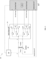
- FIG. 2 depicts a diagram of a system for testing a resolver driver circuit according to one or more embodiments.
- the system 200 includes a unit under test (UUT) 202.
- the UUT 202 is a resolver driver circuit that is utilized for determining a resolver angular position.
- the testing described herein determines whether the excitation signal from the UUT 202 as well as the sine and cosine channel inputs of the UUT 202 are operating correctly.
- the exact angles of a resolver are mimicked (or simulated) with a combination of polarity of the signals and short conditions performed in the switch matrix 204.
- the switch matrix 204 includes a first set of switches (SW1 - SW5) for controlling the input signal for the sine channel input of the UUT 202.
- the switch matrix 204 also includes a second set of switches (SW6 - SW10) for controlling the input signal for the cosine channel input of the UUT 202.
- An excitation signal is supplied from the UUT 202 and the channel is connected to an isolator 206.
- the excitation signal is supplied from a positive terminal and a negative terminal on the UUT.
- the sine and cosine inputs of the UUT each a positive terminal and negative terminal.
- the system 200 utilizes a finite set of angles (0, 45, 90, 135, 180, 225, and 270 degrees). For each of the angles described, the switching operation is done according to the following Table 1. Table 1 - NC - normally close; NO - normally open, X - don't care condition Angle Sine Channel Cosine Channel Sine Channel switch configuration Cosine Channel switch configuration SW1 SW 2 SW 3 SW 4 SW 5 SW 6 SW 7 SW 8 SW 9 SW1 0 0°(360°) Zero Excitation + - OFF OFF X X ON ON ON NC NC OFF 45° Excitation + - Excitation + - ON ON NC NC OFF ON ON NC NC OFF 90° Excitation + - Zero ON ON NC NC OFF OFF OFF X X ON 135° Excitation + - Excitation - + ON ON NC NC OFF ON ON NO NO NO OFF 180°(-180°) Zero Excitation - + OFF OFF X X ON ON ON NO NO NO OFF
- the sine channel is shorted with SW5 being on thus blocking the sine channel signal input.
- the cosine channel is the excitation signal as SW6, SW7, SW8, and SW9 allow a path from the positive terminal of the excitation channel being connected to the positive terminal of the cosine channel input and the negative terminal of the excitation channel is connected to the negative terminal of the cosine channel input.
- the sine channel input will be excitation signals and the cosine channel input will be excitation.
- the sine input will be the excitation signal, however, the cosine will be at negative excitation signal.
- the cosine has an opposite polarity where the positive cosine input is connected to the negative excitation output and the negative cosine input is connected to the positive excitation output.
- the remaining angles are described in Table 1 with the corresponding switching operation of the first and second set of switches in the switching matrix 204.
- the testing is designed to verify the UUT 202 is functioning correctly and with high accuracy at selected resolver angles.
- the system 200 includes a controller 208 which is utilized to operate the switching matrix 204 as shown in Table 1.
- the controller 208 is also utilized for testing by measuring the excitation signal from the UUT 202 and also communicating with the UUT 202 to determine whether the correct signal is received at the sine channel input and the cosine channel inputs.
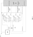
- FIG. 3 depicts a diagram of a system for testing a resolver driver circuit according to one or more embodiments.
- the system 300 includes a unit under test (UUT) 302.
- the UUT 302 is a resolver driver circuit that is utilized for determining a resolver angular position.
- the testing described herein determines whether the excitation signal from the UUT 302 as well as the sine and cosine channel inputs of the UUT 302 are operating correctly.
- the exact angles of a resolver are mimicked (or simulated) with a combination of polarity of the signals and short conditions performed in the switch matrix 304.
- the switch matrix 304 includes four decks (deck 1 - deck 4) that each have eight (8) poles that can be selected.
- the decks share a common control where if Deck 1 is selecting pole 3, for example, the other three decks (Deck 2 - Deck 4) are selecting their respective pole 3.
- the excitation signal from the UUT 302 is connected to the switching matrix 304 through an isolator 306 which can be, for example, an isolation transformer.
- Each deck output is connected to a channel leading to a terminal of the sine channel input and the cosine channel input.
- the excitation signal is supplied to the terminals of the sine and cosine channel inputs in order to mimic angles of a resolver. For example, at 0 degree angle, all the decks are selecting pole 1. This results in a zeroed signal to the sine channel input and a positive excitation to the cosine channel input.
- the system 300 includes a controller 308 that can be utilized to determine the correct functioning of the UUT 302 by monitoring the excitation signal and the inputs from the sine channel input and the cosine channel input.
- the controller 308 can operate the switching matrix 304 to control the selection of the poles for each deck.
- the switch matrix 304 can be manually operated by using a rotary switch operable to rotate the selection mechanism for each deck to select one of the poles. The manual operation can be performed by a technician testing the UUT 302, for example.
- the controller 308 can compare the received sine and cosine signal outputs from the switch matrix to what the expected signals would be based on the specified angle of the switching matrix 304. So if the controller 308 is expecting a 90 degree angle but there is a signal received at the cosine channel input, the controller 308 can determine a fault exists in the UUT 302 and alert the technician to repair and/or replace the UUT 302. Otherwise, if the specified angle for the switch matrix 304 matches the expected sine and cosine inputs, the UUT 302 can be presumed to be functioning correctly.
- FIG. 4 depicts a flow diagram of a method for testing a resolver circuit according to one or more embodiments.
- the method 400 includes operating a resolver circuit to output an excitation signal to a switching matrix, wherein the switching matrix comprises an excitation input connected to an excitation signal output of the resolver circuit, a first output connected to a sine signal input of the resolver circuit, and a second output connected to a cosine signal input of the resolver circuit, wherein the switching matrix further comprises a set of switches configured to route an excitation signal from the resolver circuit to mimic a sine and cosine signal output corresponding to a specified angle for a resolver sensor, shown in block 402.
- the method 400 includes determining an angle value based on a sine signal received at the sine signal input and a cosine signal received at the cosine signal input from the switching matrix, as shown in block 404. And at block 406, the method 400 includes comparing the angle value to the specified angle for the resolver sensor to determine a fault condition in the resolver circuit.
Landscapes
- Physics & Mathematics (AREA)
- General Physics & Mathematics (AREA)
- Transmission And Conversion Of Sensor Element Output (AREA)
Abstract
Description
- This application relates to resolvers.
- The present invention generally relates to resolvers, and more specifically to, a standalone resolver angle verification method to achieve high measurement accuracy.
- Resolvers are used in a variety of applications to provide position feedback. For example, resolvers are oftentimes associated with actuators to provide feedback regarding the state of the actuator (e.g., open, partially open, closed). A typical resolver includes an excitation coil and first and second secondary coils positioned 90° out of phase with one another. An excitation signal supplied to the excitation coil generates corresponding output signals in the first and second secondary coils. By comparing the phase of the excitation signal to the phase of the output signals, the orientation or position of the resolver shaft can be determined.
- Typically, a resolver circuit monitors the excitation signal and the corresponding output signals simultaneously to determine position. However, in some applications, a multiplexer is used to sample the respective signals successively as opposed to simultaneously. For these applications, the resolver position is only determinable within a 90° range. If the resolver position rotates more than 90°, the position cannot be determined without knowledge of the quadrant in which the position is located. For example, a first quadrant may represent angles from 0-90°, the second quadrant represents angles from 90-180°, the third quadrant represents angles from 180-270°, and the third quadrant represents angles from 270-360°. In these applications, the magnitude alone is insufficient to determine position.
- Embodiments of the present invention are directed to a system. A non-limiting example of the system includes a resolver circuit comprising an excitation signal output, a sine signal input, and a cosine signal input, a switching matrix comprising an excitation input connected to the excitation signal output, a first output connected to the sine signal input, and a second output connected to the cosine signal input, wherein the switching matrix further comprises a set of switches configured to route an excitation signal from the resolver circuit to mimic a sine and cosine signal output corresponding to a specified angle for a resolver sensor, a controller configured to operate the resolver circuit to output an excitation signal to the switching matrix, determine an angle value based on a sine signal received at the sine signal input and a cosine signal received at the cosine signal input from the switching matrix, and compare the angle value to the specified angle for the resolver sensor to determine a fault condition in the resolver circuit.
- In embodiments of the system may include that the switch matrix operation is controlled by the controller.
- In embodiments of the system may include that the switch matrix operation is controlled by a manual rotary switch.
- In embodiments of the system may include that the specified angle is 0 degrees, the sine signal output comprises zero, and the cosine signal output comprises the excitation signal.
- In embodiments of the system may include that the specified angle is 135 degrees, the sine signal output comprises the excitation signal, and the cosine signal output comprises a negative of the excitation signal.
- In embodiments of the system may include that the specified angle is 270 degrees, the sine signal output comprises a negative of the excitation signal, and the cosine signal output comprises zero.
- In embodiments of the system may include that the specified angle is 315 degrees, the sine signal output comprises a negative of the excitation signal, and the cosine signal output comprises the excitation signal.
- In embodiments of the system may include an isolator connected between the excitation signal output and the excitation input of the switching matrix.
- In embodiments of the system may include that the isolator comprises an isolation transformer.
- In embodiments of the system may include that
Embodiments of the present invention are directed to a method. A non-limiting example of the method includes operating a resolver circuit to output an excitation signal to a switching matrix, wherein the switching matrix comprises an excitation input connected to an excitation signal output of the resolver circuit, a first output connected to a sine signal input of the resolver circuit, and a second output connected to a cosine signal input of the resolver circuit, wherein the switching matrix further comprises a set of switches configured to route an excitation signal from the resolver circuit to mimic a sine and cosine signal output corresponding to a specified angle for a resolver sensor, determining an angle value based on a sine signal received at the sine signal input and a cosine signal received at the cosine signal input from the switching matrix, and comparing the angle value to the specified angle for the resolver sensor to determine a fault condition in the resolver circuit. - In embodiments of the system may include that the specified angle comprises a set of eight test angles.
- In embodiments of the system may include that the switch matrix operation is controlled by the controller.
- In embodiments of the system may include that the switch matrix operation is controlled by a manual rotary switch.
- In embodiments of the system may include that the specified angle is 0 degrees, the sine signal output comprises zero, and the cosine signal output comprises the excitation signal.
- In embodiments of the system may include that the specified angle is 135 degrees, the sine signal output comprises the excitation signal, and the cosine signal output comprises a negative of the excitation signal.
- In embodiments of the system may include that the specified angle is 270 degrees, the sine signal output comprises a negative of the excitation signal, and the cosine signal output comprises zero.
- In embodiments of the system may include that the specified angle is 315 degrees, the sine signal output comprises a negative of the excitation signal, and the cosine signal output comprises the excitation signal.
- In embodiments of the system may include that an isolator is connected between the excitation signal output and the switching matrix.
- In embodiments of the system may include that the isolator comprises an isolation transformer.
- Additional technical features and benefits are realized through the techniques of the present invention. Embodiments and aspects of the invention are described in detail herein and are considered a part of the claimed subject matter. For a better understanding, refer to the detailed description and to the drawings.
- The specifics of the exclusive rights described herein are particularly pointed out and distinctly claimed in the claims at the conclusion of the specification. The foregoing and other features and advantages of the embodiments of the invention are apparent from the following detailed description taken in conjunction with the accompanying drawings in which:
-
FIG. 1 is a perspective view of an aircraft that may incorporate embodiments of the present disclosure; -
FIG. 2 depicts a diagram of a system for testing a resolver interface circuit according to one or more embodiments; -
FIG. 3 depicts a diagram of a system for testing a resolver interface circuit according to one or more embodiments; and -
FIG. 4 depicts a flow diagram of a method for testing a resolver interface according to one or more embodiments. - The diagrams depicted herein are illustrative. There can be many variations to the diagram or the operations described therein without departing from the spirit of the invention. For instance, the actions can be performed in a differing order or actions can be added, deleted or modified. Also, the term "coupled" and variations thereof describes having a communications path between two elements and does not imply a direct connection between the elements with no intervening elements/connections between them. All of these variations are considered a part of the specification.
-
FIG. 1 illustrates an example of acommercial aircraft 10 havingaircraft engines 20 that may embody aspects of the teachings of this disclosure. Theaircraft 10 includes twowings 22 that each include one ormore slats 24 and one ormore flaps 26. The aircraft further includesailerons 27,spoilers 28, horizontalstabilizer trim tabs 29,rudder 30 andhorizontal stabilizer 31. The term "control surface" used herein includes but is not limited to either a slat or a flap or any of the above described. It will be understood that theslats 24 and/or theflaps 26 can include one or more slat/flap panels that move together. Theaircraft 10 also includes a resolver interface circuit 202 (described in greater detail inFIG. 2 ) that measures the angles of a resolver that is used onboard theaircraft 10. Theseresolver interface circuits 202 need to be tested from time to time to make sure they are functioning correctly. - Turning now to an overview of technologies that are more specifically relevant to aspects of the disclosure, for testing a resolver secondary interface circuit (driver) sine and cosine input channels, two separate sources synchronized to the excitation signal are needed. In typical configurations, a signal generator is utilized, the signal generator includes sophisticated digital to analog converter (DAC) cards interfaced with a processor. With this configuration, the DAC outputs have to be matched for precision with the excitation source for accurate angle verification each time. This synchronization is complex and the error induced can be significantly large. Voltage inaccuracies, frequency limitations and isolation in each DAC channel likewise contributes to additional error potentials. This typical test setup is expensive because of the high end analog to digital conversation (ADC) and DAC cards with waveform processors and software interfaces that are needed.
- One or more embodiments described herein address the above described shortcomings of the typical configuration by eliminating the complexities involved in synchronization between excitation from a unit under test (UUT) and the sine and cosine outputs. The UUT herein refers to the resolver secondary interface circuit. In one or more embodiments, this novel configuration uses an isolator and a switch matrix and excitation signal from the UUT to simulate variable angle positions at the resolver secondary interface. The isolator can be an isolation transformer, for example. The switch matrix is built around a multi-pole rotary switch or can be automated with relays. Exact angles can be simulated with a combination of polarity of signals and short conditions at the resolver secondary interface inputs in the UUT. The polarity of the signals and a short condition to the sine and cosine channels can be configured with the assistance of a switch matrix. Benefits of this novel configuration include the elimination of synchronization issues due to a single source being involved. To check the overall range, it is sufficient to measure just a few angles as described later herein.
-
FIG. 2 depicts a diagram of a system for testing a resolver driver circuit according to one or more embodiments. Thesystem 200 includes a unit under test (UUT) 202. TheUUT 202 is a resolver driver circuit that is utilized for determining a resolver angular position. The testing described herein determines whether the excitation signal from theUUT 202 as well as the sine and cosine channel inputs of theUUT 202 are operating correctly. The exact angles of a resolver are mimicked (or simulated) with a combination of polarity of the signals and short conditions performed in theswitch matrix 204. Theswitch matrix 204 includes a first set of switches (SW1 - SW5) for controlling the input signal for the sine channel input of theUUT 202. Theswitch matrix 204 also includes a second set of switches (SW6 - SW10) for controlling the input signal for the cosine channel input of theUUT 202. An excitation signal is supplied from theUUT 202 and the channel is connected to anisolator 206. The excitation signal is supplied from a positive terminal and a negative terminal on the UUT. The sine and cosine inputs of the UUT each a positive terminal and negative terminal. With the operation of the switches in theswitch matrix 204, a set of angles are mimicked for testing whether theUUT 202 operating properly. It is not necessary to check every angle to verify the quality of the UUT resolver interface. Instead of doing every angle from 0 to 360 degree rotation, thesystem 200 utilizes a finite set of angles (0, 45, 90, 135, 180, 225, and 270 degrees). For each of the angles described, the switching operation is done according to the following Table 1.Table 1 - NC - normally close; NO - normally open, X - don't care condition Angle Sine Channel Cosine Channel Sine Channel switch configuration Cosine Channel switch configuration SW1 SW 2 SW 3SW 4SW 5SW 6 SW 7 SW 8SW 9SW1 0 0°(360°) Zero Excitation + - OFF OFF X X ON ON ON NC NC OFF 45° Excitation + - Excitation + - ON ON NC NC OFF ON ON NC NC OFF 90° Excitation + - Zero ON ON NC NC OFF OFF OFF X X ON 135° Excitation + - Excitation - + ON ON NC NC OFF ON ON NO NO OFF 180°(-180°) Zero Excitation - + OFF OFF X X ON ON ON NO NO OFF 225° (-135°) Excitation - + Excitation - + ON ON NO NO OFF ON ON NO NO OFF 270°(-90°) Excitation - + Zero ON ON NO NO OFF OFF OFF X X ON 315°(-45°) Excitation - + Excitation + - ON ON NO NO OFF ON ON NC NC OFF - At 0 degrees, the sine channel is shorted with SW5 being on thus blocking the sine channel signal input. The cosine channel is the excitation signal as SW6, SW7, SW8, and SW9 allow a path from the positive terminal of the excitation channel being connected to the positive terminal of the cosine channel input and the negative terminal of the excitation channel is connected to the negative terminal of the cosine channel input. Similarly, at 45 degrees, the sine channel input will be excitation signals and the cosine channel input will be excitation. At 135 degrees, the sine input will be the excitation signal, however, the cosine will be at negative excitation signal. The cosine has an opposite polarity where the positive cosine input is connected to the negative excitation output and the negative cosine input is connected to the positive excitation output. The remaining angles are described in Table 1 with the corresponding switching operation of the first and second set of switches in the switching
matrix 204. The testing is designed to verify theUUT 202 is functioning correctly and with high accuracy at selected resolver angles. - In one or more embodiments, the
system 200 includes acontroller 208 which is utilized to operate the switchingmatrix 204 as shown in Table 1. Thecontroller 208 is also utilized for testing by measuring the excitation signal from theUUT 202 and also communicating with theUUT 202 to determine whether the correct signal is received at the sine channel input and the cosine channel inputs. -
FIG. 3 depicts a diagram of a system for testing a resolver driver circuit according to one or more embodiments. Thesystem 300 includes a unit under test (UUT) 302. TheUUT 302 is a resolver driver circuit that is utilized for determining a resolver angular position. The testing described herein determines whether the excitation signal from theUUT 302 as well as the sine and cosine channel inputs of theUUT 302 are operating correctly. The exact angles of a resolver are mimicked (or simulated) with a combination of polarity of the signals and short conditions performed in theswitch matrix 304. Theswitch matrix 304 includes four decks (deck 1 - deck 4) that each have eight (8) poles that can be selected. The decks share a common control where ifDeck 1 is selectingpole 3, for example, the other three decks (Deck 2 - Deck 4) are selecting theirrespective pole 3. The excitation signal from theUUT 302 is connected to the switchingmatrix 304 through anisolator 306 which can be, for example, an isolation transformer. Each deck output is connected to a channel leading to a terminal of the sine channel input and the cosine channel input. Similarly toFIG. 2 , the excitation signal is supplied to the terminals of the sine and cosine channel inputs in order to mimic angles of a resolver. For example, at 0 degree angle, all the decks are selectingpole 1. This results in a zeroed signal to the sine channel input and a positive excitation to the cosine channel input. The remaining angles for the resolver for testing are shown with reference to Table 2 below.Table 2 Knob positi on Pole Num her Rotatory switch configuration for Rotatory switch configuration for Sine Channel Cosine Channel Sine Channel Port Cosine Channel Port Input Input Deck 1 Indexes Deck 2 Indexes Deck 3 Indexes Deck 4 Indexes Sine Positive pin Sine Negative pin Cosine Positive pin Cosine Negative pin 0° (360°) Pole -1 Deck 2Position 1Deck 1Position 1Excitation + Excitation - Zero (Short) Excitatio n
+ -45° Pole -2 Excitation + Excitation - Excitation + Excitation - Excitati on Excitatio n + - + - 90° Pole -3 Excitation + Excitation - Deck 4Position 3Deck 3Position 3Excitati on Zero (Short) + - 135° Pole -4 Excitation + Excitation - Excitation - Excitation + Excitati on Excitatio n + - - + 180° (-180°) Pole -5 Deck 2Position 5Deck 1Position 5Excitation - Excitation + Zero (Short) Excitatio n - + 225° (-135°) Pole -6 Excitation - Excitation + Excitation - Excitation + Excitati on Excitatio n - + - + 270° (-90°) Pole -7 Excitation - Excitation + Deck 4 Position 7Deck 3 Position 7Excitati on Zero (Short) - + 315° (-45°) Pole -8 Excitation - Excitation + Excitation + Excitation - Excitati on Excitatio n - + + - - In one or more embodiments, the
system 300 includes acontroller 308 that can be utilized to determine the correct functioning of theUUT 302 by monitoring the excitation signal and the inputs from the sine channel input and the cosine channel input. Optionally, thecontroller 308 can operate the switchingmatrix 304 to control the selection of the poles for each deck. In other embodiments, theswitch matrix 304 can be manually operated by using a rotary switch operable to rotate the selection mechanism for each deck to select one of the poles. The manual operation can be performed by a technician testing theUUT 302, for example. - The
controller 308 can compare the received sine and cosine signal outputs from the switch matrix to what the expected signals would be based on the specified angle of the switchingmatrix 304. So if thecontroller 308 is expecting a 90 degree angle but there is a signal received at the cosine channel input, thecontroller 308 can determine a fault exists in theUUT 302 and alert the technician to repair and/or replace theUUT 302. Otherwise, if the specified angle for theswitch matrix 304 matches the expected sine and cosine inputs, theUUT 302 can be presumed to be functioning correctly. -
FIG. 4 depicts a flow diagram of a method for testing a resolver circuit according to one or more embodiments. Themethod 400 includes operating a resolver circuit to output an excitation signal to a switching matrix, wherein the switching matrix comprises an excitation input connected to an excitation signal output of the resolver circuit, a first output connected to a sine signal input of the resolver circuit, and a second output connected to a cosine signal input of the resolver circuit, wherein the switching matrix further comprises a set of switches configured to route an excitation signal from the resolver circuit to mimic a sine and cosine signal output corresponding to a specified angle for a resolver sensor, shown inblock 402. Also, themethod 400 includes determining an angle value based on a sine signal received at the sine signal input and a cosine signal received at the cosine signal input from the switching matrix, as shown inblock 404. And atblock 406, themethod 400 includes comparing the angle value to the specified angle for the resolver sensor to determine a fault condition in the resolver circuit. - A detailed description of one or more embodiments of the disclosed apparatus and method are presented herein by way of exemplification and not limitation with reference to the Figures.
- The term "about" is intended to include the degree of error associated with measurement of the particular quantity based upon the equipment available at the time of filing the application.
- The terminology used herein is for the purpose of describing particular embodiments only and is not intended to be limiting of the present disclosure. As used herein, the singular forms "a", "an" and "the" are intended to include the plural forms as well, unless the context clearly indicates otherwise. It will be further understood that the terms "comprises" and/or "comprising," when used in this specification, specify the presence of stated features, integers, steps, operations, elements, and/or components, but do not preclude the presence or addition of one or more other features, integers, steps, operations, element components, and/or groups thereof.
- While the present disclosure has been described with reference to an exemplary embodiment or embodiments, it will be understood by those skilled in the art that various changes may be made without departing from the scope of the invention as defined by the claims. In addition, many modifications may be made to adapt a particular situation or material to the teachings of the present disclosure without departing from the scope of the claims. Therefore, it is intended that the present disclosure not be limited to the particular embodiment disclosed as the best mode contemplated for carrying out this present disclosure, but that the present disclosure will include all embodiments falling within the scope of the claims.
Claims (15)
- A system for testing a resolver circuit comprising:a resolver circuit (202) comprising an excitation signal output, a sine signal input, and a cosine signal input,a switching matrix (204) comprising an excitation input connected to the excitation signal output, a first output connected to the sine signal input, and a second output connected to the cosine signal input, wherein the switching matrix further comprises a set of switches configured to route an excitation signal from the resolver circuit to mimic a sine and cosine signal output corresponding to a specified angle for a resolver sensor;a controller (208) configured to:operate the resolver circuit to output an excitation signal to the switching matrix;determine an angle value based on a sine signal received at the sine signal input and a cosine signal received at the cosine signal input from the switching matrix;compare the angle value to the specified angle for the resolver sensor to determine a fault condition in the resolver circuit.
- The system of Claim 1, wherein the specified angle comprises a set of eight test angles.
- The system of Claim 1 or 2, wherein the switch matrix operation is controlled by the controller or wherein the switch matrix operation is controlled by a manual rotary switch.
- The system of any preceding Claim, wherein the specified angle is 0 degrees; andwherein the sine signal output comprises zero; andwherein the cosine signal output comprises the excitation signal; orwherein the specified angle is 135 degrees; andwherein the sine signal output comprises the excitation signal; andwherein the cosine signal output comprises a negative of the excitation signal, orwherein the specified angle is 270 degrees; andwherein the sine signal output comprises a negative of the excitation signal; andwherein the cosine signal output comprises zero; orwherein the specified angle is 315 degrees; andwherein the sine signal output comprises a negative of the excitation signal; andwherein the cosine signal output comprises the excitation signal.
- The system of any preceding Claim, further comprising an isolator connected between the excitation signal output and the excitation input of the switching matrix.
- The system of Claim 5, wherein the isolator comprises an isolation transformer.
- A method for testing a resolver circuit comprising:operating a resolver circuit to output an excitation signal to a switching matrix, wherein the switching matrix comprises an excitation input connected to an excitation signal output of the resolver circuit, a first output connected to a sine signal input of the resolver circuit, and a second output connected to a cosine signal input of the resolver circuit, wherein the switching matrix further comprises a set of switches configured to route an excitation signal from the resolver circuit to mimic a sine and cosine signal output corresponding to a specified angle for a resolver sensor;determining an angle value based on a sine signal received at the sine signal input and a cosine signal received at the cosine signal input from the switching matrix; andcomparing the angle value to the specified angle for the resolver sensor to determine a fault condition in the resolver circuit.
- The method of Claim 7, wherein the specified angle comprises a set of eight test angles.
- The method of Claim 7 or 8, wherein the switch matrix operation is controlled by the controller, or wherein the switch matrix operation is controlled by a manual rotary switch.
- The method of Claim 7, 8 or 9, wherein the specified angle is 0 degrees; andwherein the sine signal output comprises zero; andwherein the cosine signal output comprises the excitation signal.
- The method of Claim 7, 8 or 9, wherein the specified angle is 135 degrees; andwherein the sine signal output comprises the excitation signal; andwherein the cosine signal output comprises a negative of the excitation signal.
- The method of Claim 7, 8 or 9, wherein the specified angle is 270 degrees; andwherein the sine signal output comprises a negative of the excitation signal; andwherein the cosine signal output comprises zero.
- The method of Claim 7, 8 or 9, wherein the specified angle is 315 degrees; andwherein the sine signal output comprises a negative of the excitation signal; andwherein the cosine signal output comprises the excitation signal.
- The method of Claim 7, 8 or 9, wherein an isolator is connected between the excitation signal output and the switching matrix.
- The method of Claim 14, wherein the isolator comprises an isolation transformer.
Applications Claiming Priority (1)
| Application Number | Priority Date | Filing Date | Title |
|---|---|---|---|
| IN202211018924 | 2022-03-30 |
Publications (2)
| Publication Number | Publication Date |
|---|---|
| EP4253914A1 true EP4253914A1 (en) | 2023-10-04 |
| EP4253914B1 EP4253914B1 (en) | 2026-01-14 |
Family
ID=85775909
Family Applications (1)
| Application Number | Title | Priority Date | Filing Date |
|---|---|---|---|
| EP23164464.2A Active EP4253914B1 (en) | 2022-03-30 | 2023-03-27 | Standalone resolver angle verification |
Country Status (2)
| Country | Link |
|---|---|
| US (1) | US12055390B2 (en) |
| EP (1) | EP4253914B1 (en) |
Citations (3)
| Publication number | Priority date | Publication date | Assignee | Title |
|---|---|---|---|---|
| JPH0212014A (en) * | 1988-06-30 | 1990-01-17 | Okuma Mach Works Ltd | Detector and detection circuit of absolute position |
| JPH0555006U (en) * | 1991-12-25 | 1993-07-23 | 多摩川精機株式会社 | Angle converter |
| US20140114631A1 (en) * | 2008-06-22 | 2014-04-24 | United Electronic Industries | Dynamically powering a position and angle digital detection and simulation output |
Family Cites Families (9)
| Publication number | Priority date | Publication date | Assignee | Title |
|---|---|---|---|---|
| US4298874A (en) * | 1977-01-17 | 1981-11-03 | The Austin Company | Method and apparatus for tracking objects |
| US7863850B2 (en) | 2007-05-11 | 2011-01-04 | GM Global Technology Operations LLC | Apparatus, system, and method for simulating outputs of a resolver to test motor-resolver systems |
| JP4669859B2 (en) | 2007-06-29 | 2011-04-13 | 富士通テン株式会社 | Simulated resolver, motor simulator, and motor simulation method |
| US7977936B2 (en) * | 2008-10-16 | 2011-07-12 | Hamilton Sundstrand Corporation | Resolver interface and signal conditioner |
| JP5422401B2 (en) | 2010-01-07 | 2014-02-19 | 川崎重工業株式会社 | Resolver signal conversion apparatus and method |
| CN107076577B (en) | 2014-11-06 | 2019-07-23 | 三菱电机株式会社 | Rotation angle detection device and rotation angle detection method |
| JP2019219247A (en) | 2018-06-19 | 2019-12-26 | 株式会社デンソー | Resolver signal processing circuit |
| KR102575175B1 (en) | 2018-07-27 | 2023-09-05 | 현대자동차 주식회사 | Apparatus and method of retificating resolver output signal |
| JP7241660B2 (en) | 2019-10-08 | 2023-03-17 | ルネサスエレクトロニクス株式会社 | Resolver correction device and correction method for resolver correction device |
-
2022
- 2022-05-25 US US17/752,939 patent/US12055390B2/en active Active
-
2023
- 2023-03-27 EP EP23164464.2A patent/EP4253914B1/en active Active
Patent Citations (3)
| Publication number | Priority date | Publication date | Assignee | Title |
|---|---|---|---|---|
| JPH0212014A (en) * | 1988-06-30 | 1990-01-17 | Okuma Mach Works Ltd | Detector and detection circuit of absolute position |
| JPH0555006U (en) * | 1991-12-25 | 1993-07-23 | 多摩川精機株式会社 | Angle converter |
| US20140114631A1 (en) * | 2008-06-22 | 2014-04-24 | United Electronic Industries | Dynamically powering a position and angle digital detection and simulation output |
Also Published As
| Publication number | Publication date |
|---|---|
| EP4253914B1 (en) | 2026-01-14 |
| US20230314119A1 (en) | 2023-10-05 |
| US12055390B2 (en) | 2024-08-06 |
Similar Documents
| Publication | Publication Date | Title |
|---|---|---|
| US5012181A (en) | Apparatus for and method of internally calibrating an electrical calibrator | |
| US7812589B2 (en) | Modified current source (MCS) with seamless range switching | |
| CN107145182B (en) | Input voltage pattern intends resistor and resistance control method | |
| EP4253914B1 (en) | Standalone resolver angle verification | |
| US9835656B2 (en) | Method and device for measuring current at a converter | |
| CN102929321A (en) | Analog quantity conditioning and distributing device with high precision and all-digital calibration | |
| CN118566814B (en) | Automatic test equipment and current source calibration method | |
| JPS62212757A (en) | Signal dispersion system switching module | |
| CN108132452B (en) | Test calibration board for signal acquisition board and calibration and test method thereof | |
| US6556937B1 (en) | Synchro/resolver bridge and automatic test system | |
| DE102019118709A1 (en) | Comparator diagnostic systems and procedures | |
| CN113541689B (en) | Automatic calibration circuit and calibration method for analog acquisition potentiometer-free | |
| RU2727334C1 (en) | Automated control system for electrical values of electronic equipment | |
| CN102200778A (en) | Device for automatically calibrating parameters of regulators | |
| US20230175867A1 (en) | Ratiometric position measurement | |
| US12130320B2 (en) | Measuring device | |
| JPH05133997A (en) | Calibration method for IC test apparatus | |
| US4262248A (en) | System for servicing process instrumentation | |
| CN121306762A (en) | A method for adjusting the angle error of a dual-channel RVDT | |
| RU2615850C1 (en) | Control-testing complex for autopilot checking | |
| CN114553227A (en) | Timing calibration device and method for multi-channel group | |
| CN114578207B (en) | A high-precision integrated operational amplifier nonlinearity test system and test method | |
| EP4043891B1 (en) | Isolation measurement monitoring for asil applications | |
| JP3075667B2 (en) | Offline teaching data correction method | |
| CN117602097A (en) | Application method of helicopter autopilot detection device |
Legal Events
| Date | Code | Title | Description |
|---|---|---|---|
| PUAI | Public reference made under article 153(3) epc to a published international application that has entered the european phase |
Free format text: ORIGINAL CODE: 0009012 |
|
| STAA | Information on the status of an ep patent application or granted ep patent |
Free format text: STATUS: THE APPLICATION HAS BEEN PUBLISHED |
|
| AK | Designated contracting states |
Kind code of ref document: A1 Designated state(s): AL AT BE BG CH CY CZ DE DK EE ES FI FR GB GR HR HU IE IS IT LI LT LU LV MC ME MK MT NL NO PL PT RO RS SE SI SK SM TR |
|
| STAA | Information on the status of an ep patent application or granted ep patent |
Free format text: STATUS: REQUEST FOR EXAMINATION WAS MADE |
|
| 17P | Request for examination filed |
Effective date: 20240403 |
|
| RBV | Designated contracting states (corrected) |
Designated state(s): AL AT BE BG CH CY CZ DE DK EE ES FI FR GB GR HR HU IE IS IT LI LT LU LV MC ME MK MT NL NO PL PT RO RS SE SI SK SM TR |
|
| GRAP | Despatch of communication of intention to grant a patent |
Free format text: ORIGINAL CODE: EPIDOSNIGR1 |
|
| STAA | Information on the status of an ep patent application or granted ep patent |
Free format text: STATUS: GRANT OF PATENT IS INTENDED |
|
| INTG | Intention to grant announced |
Effective date: 20250909 |
|
| GRAS | Grant fee paid |
Free format text: ORIGINAL CODE: EPIDOSNIGR3 |
|
| GRAA | (expected) grant |
Free format text: ORIGINAL CODE: 0009210 |
|
| STAA | Information on the status of an ep patent application or granted ep patent |
Free format text: STATUS: THE PATENT HAS BEEN GRANTED |
|
| AK | Designated contracting states |
Kind code of ref document: B1 Designated state(s): AL AT BE BG CH CY CZ DE DK EE ES FI FR GB GR HR HU IE IS IT LI LT LU LV MC ME MK MT NL NO PL PT RO RS SE SI SK SM TR |
|
| REG | Reference to a national code |
Ref country code: CH Ref legal event code: F10 Free format text: ST27 STATUS EVENT CODE: U-0-0-F10-F00 (AS PROVIDED BY THE NATIONAL OFFICE) Effective date: 20260114 Ref country code: GB Ref legal event code: FG4D |
|
| REG | Reference to a national code |
Ref country code: DE Ref legal event code: R096 Ref document number: 602023010604 Country of ref document: DE |
|
| REG | Reference to a national code |
Ref country code: IE Ref legal event code: FG4D |
|
| PGFP | Annual fee paid to national office [announced via postgrant information from national office to epo] |
Ref country code: AT Payment date: 20260301 Year of fee payment: 4 |
|
| PGFP | Annual fee paid to national office [announced via postgrant information from national office to epo] |
Ref country code: FR Payment date: 20260220 Year of fee payment: 4 |
|
| REG | Reference to a national code |
Ref country code: NL Ref legal event code: MP Effective date: 20260114 |
|
| PG25 | Lapsed in a contracting state [announced via postgrant information from national office to epo] |
Ref country code: NL Free format text: LAPSE BECAUSE OF FAILURE TO SUBMIT A TRANSLATION OF THE DESCRIPTION OR TO PAY THE FEE WITHIN THE PRESCRIBED TIME-LIMIT Effective date: 20260114 |
|
| REG | Reference to a national code |
Ref country code: AT Ref legal event code: MK05 Ref document number: 1877392 Country of ref document: AT Kind code of ref document: T Effective date: 20260114 |
|
| PG25 | Lapsed in a contracting state [announced via postgrant information from national office to epo] |
Ref country code: RS Free format text: LAPSE BECAUSE OF FAILURE TO SUBMIT A TRANSLATION OF THE DESCRIPTION OR TO PAY THE FEE WITHIN THE PRESCRIBED TIME-LIMIT Effective date: 20260414 |
|
| PG25 | Lapsed in a contracting state [announced via postgrant information from national office to epo] |
Ref country code: ES Free format text: LAPSE BECAUSE OF FAILURE TO SUBMIT A TRANSLATION OF THE DESCRIPTION OR TO PAY THE FEE WITHIN THE PRESCRIBED TIME-LIMIT Effective date: 20260114 |
|
| PG25 | Lapsed in a contracting state [announced via postgrant information from national office to epo] |
Ref country code: PL Free format text: LAPSE BECAUSE OF FAILURE TO SUBMIT A TRANSLATION OF THE DESCRIPTION OR TO PAY THE FEE WITHIN THE PRESCRIBED TIME-LIMIT Effective date: 20260114 |
|
| PG25 | Lapsed in a contracting state [announced via postgrant information from national office to epo] |
Ref country code: GR Free format text: LAPSE BECAUSE OF FAILURE TO SUBMIT A TRANSLATION OF THE DESCRIPTION OR TO PAY THE FEE WITHIN THE PRESCRIBED TIME-LIMIT Effective date: 20260415 |
|
| REG | Reference to a national code |
Ref country code: LT Ref legal event code: MG9D |
|
| PG25 | Lapsed in a contracting state [announced via postgrant information from national office to epo] |
Ref country code: LT Free format text: LAPSE BECAUSE OF FAILURE TO SUBMIT A TRANSLATION OF THE DESCRIPTION OR TO PAY THE FEE WITHIN THE PRESCRIBED TIME-LIMIT Effective date: 20260114 |
|
| PG25 | Lapsed in a contracting state [announced via postgrant information from national office to epo] |
Ref country code: NO Free format text: LAPSE BECAUSE OF FAILURE TO SUBMIT A TRANSLATION OF THE DESCRIPTION OR TO PAY THE FEE WITHIN THE PRESCRIBED TIME-LIMIT Effective date: 20260414 |
|
| PG25 | Lapsed in a contracting state [announced via postgrant information from national office to epo] |
Ref country code: SE Free format text: LAPSE BECAUSE OF FAILURE TO SUBMIT A TRANSLATION OF THE DESCRIPTION OR TO PAY THE FEE WITHIN THE PRESCRIBED TIME-LIMIT Effective date: 20260114 Ref country code: AT Free format text: LAPSE BECAUSE OF FAILURE TO SUBMIT A TRANSLATION OF THE DESCRIPTION OR TO PAY THE FEE WITHIN THE PRESCRIBED TIME-LIMIT Effective date: 20260114 Ref country code: FI Free format text: LAPSE BECAUSE OF FAILURE TO SUBMIT A TRANSLATION OF THE DESCRIPTION OR TO PAY THE FEE WITHIN THE PRESCRIBED TIME-LIMIT Effective date: 20260114 |
|
| PG25 | Lapsed in a contracting state [announced via postgrant information from national office to epo] |
Ref country code: HR Free format text: LAPSE BECAUSE OF FAILURE TO SUBMIT A TRANSLATION OF THE DESCRIPTION OR TO PAY THE FEE WITHIN THE PRESCRIBED TIME-LIMIT Effective date: 20260114 |
|
| PG25 | Lapsed in a contracting state [announced via postgrant information from national office to epo] |
Ref country code: IS Free format text: LAPSE BECAUSE OF FAILURE TO SUBMIT A TRANSLATION OF THE DESCRIPTION OR TO PAY THE FEE WITHIN THE PRESCRIBED TIME-LIMIT Effective date: 20260514 Ref country code: PT Free format text: LAPSE BECAUSE OF FAILURE TO SUBMIT A TRANSLATION OF THE DESCRIPTION OR TO PAY THE FEE WITHIN THE PRESCRIBED TIME-LIMIT Effective date: 20260514 |
|
| PG25 | Lapsed in a contracting state [announced via postgrant information from national office to epo] |
Ref country code: LV Free format text: LAPSE BECAUSE OF FAILURE TO SUBMIT A TRANSLATION OF THE DESCRIPTION OR TO PAY THE FEE WITHIN THE PRESCRIBED TIME-LIMIT Effective date: 20260114 |
|
| PG25 | Lapsed in a contracting state [announced via postgrant information from national office to epo] |
Ref country code: BG Free format text: LAPSE BECAUSE OF FAILURE TO SUBMIT A TRANSLATION OF THE DESCRIPTION OR TO PAY THE FEE WITHIN THE PRESCRIBED TIME-LIMIT Effective date: 20260114 |