EP4253876A1 - Refrigerant recovery device - Google Patents
Refrigerant recovery device Download PDFInfo
- Publication number
- EP4253876A1 EP4253876A1 EP20963476.5A EP20963476A EP4253876A1 EP 4253876 A1 EP4253876 A1 EP 4253876A1 EP 20963476 A EP20963476 A EP 20963476A EP 4253876 A1 EP4253876 A1 EP 4253876A1
- Authority
- EP
- European Patent Office
- Prior art keywords
- refrigerant
- collected
- amount
- value
- collecting apparatus
- Prior art date
- Legal status (The legal status is an assumption and is not a legal conclusion. Google has not performed a legal analysis and makes no representation as to the accuracy of the status listed.)
- Withdrawn
Links
- 239000003507 refrigerant Substances 0.000 title claims abstract description 515
- 238000011084 recovery Methods 0.000 title 1
- 239000007788 liquid Substances 0.000 claims description 78
- 238000003860 storage Methods 0.000 claims description 60
- 238000012937 correction Methods 0.000 claims description 39
- 239000012535 impurity Substances 0.000 claims description 20
- 238000000926 separation method Methods 0.000 claims description 12
- 238000012986 modification Methods 0.000 description 28
- 230000004048 modification Effects 0.000 description 28
- 238000012360 testing method Methods 0.000 description 25
- 238000004519 manufacturing process Methods 0.000 description 14
- 230000006870 function Effects 0.000 description 13
- 230000006399 behavior Effects 0.000 description 6
- 238000000034 method Methods 0.000 description 6
- 238000004891 communication Methods 0.000 description 5
- 238000010586 diagram Methods 0.000 description 5
- 238000004378 air conditioning Methods 0.000 description 4
- 238000012545 processing Methods 0.000 description 4
- NBVXSUQYWXRMNV-UHFFFAOYSA-N fluoromethane Chemical compound FC NBVXSUQYWXRMNV-UHFFFAOYSA-N 0.000 description 3
- 238000005259 measurement Methods 0.000 description 3
- 238000010792 warming Methods 0.000 description 3
- 238000005457 optimization Methods 0.000 description 2
- 230000003245 working effect Effects 0.000 description 2
- VYPSYNLAJGMNEJ-UHFFFAOYSA-N Silicium dioxide Chemical compound O=[Si]=O VYPSYNLAJGMNEJ-UHFFFAOYSA-N 0.000 description 1
- 239000003463 adsorbent Substances 0.000 description 1
- PNEYBMLMFCGWSK-UHFFFAOYSA-N aluminium oxide Inorganic materials [O-2].[O-2].[O-2].[Al+3].[Al+3] PNEYBMLMFCGWSK-UHFFFAOYSA-N 0.000 description 1
- 230000006835 compression Effects 0.000 description 1
- 238000007906 compression Methods 0.000 description 1
- 239000000428 dust Substances 0.000 description 1
- 239000012717 electrostatic precipitator Substances 0.000 description 1
- 239000004973 liquid crystal related substance Substances 0.000 description 1
- 239000010721 machine oil Substances 0.000 description 1
- 238000005057 refrigeration Methods 0.000 description 1
- 239000000741 silica gel Substances 0.000 description 1
- 229910002027 silica gel Inorganic materials 0.000 description 1
- XLYOFNOQVPJJNP-UHFFFAOYSA-N water Substances O XLYOFNOQVPJJNP-UHFFFAOYSA-N 0.000 description 1
Images





Classifications
-
- F—MECHANICAL ENGINEERING; LIGHTING; HEATING; WEAPONS; BLASTING
- F25—REFRIGERATION OR COOLING; COMBINED HEATING AND REFRIGERATION SYSTEMS; HEAT PUMP SYSTEMS; MANUFACTURE OR STORAGE OF ICE; LIQUEFACTION SOLIDIFICATION OF GASES
- F25B—REFRIGERATION MACHINES, PLANTS OR SYSTEMS; COMBINED HEATING AND REFRIGERATION SYSTEMS; HEAT PUMP SYSTEMS
- F25B45/00—Arrangements for charging or discharging refrigerant
-
- F—MECHANICAL ENGINEERING; LIGHTING; HEATING; WEAPONS; BLASTING
- F25—REFRIGERATION OR COOLING; COMBINED HEATING AND REFRIGERATION SYSTEMS; HEAT PUMP SYSTEMS; MANUFACTURE OR STORAGE OF ICE; LIQUEFACTION SOLIDIFICATION OF GASES
- F25B—REFRIGERATION MACHINES, PLANTS OR SYSTEMS; COMBINED HEATING AND REFRIGERATION SYSTEMS; HEAT PUMP SYSTEMS
- F25B2345/00—Details for charging or discharging refrigerants; Service stations therefor
- F25B2345/002—Collecting refrigerant from a cycle
Definitions
- the present disclosure relates to a refrigerant-collecting apparatus.
- refrigerant-collecting apparatuses have been used to collect a used refrigerant from refrigeration apparatuses and the like.
- management systems that manage information relating to the collected refrigerant have been known.
- a collection worker who has performed refrigerant collection work transmits, to a management apparatus, information relating to the collected refrigerant.
- the information transmitted to the management apparatus by the collection worker includes information relating to the type of the collected refrigerant.
- a refrigerant-collecting apparatus includes a first port, a second port, a refrigerant channel, and an identifying unit.
- the first port is connected to target equipment from which a refrigerant is collected.
- the second port is connected to a container in which the refrigerant collected from the target equipment is put.
- the refrigerant channel connects the first port and the second port.
- the refrigerant channel includes at least an expansion mechanism, a compressor, and a heat exchanger.
- the identifying unit identifies the type of the refrigerant that is being collected from the target equipment. On the basis of a first value and a second value, the identifying unit identifies the type of the refrigerant that is being collected from the target equipment.
- the identifying unit identifies the type of the refrigerant that is being collected from the target equipment.
- the identifying unit identifies the type of the refrigerant that is being collected from the target equipment.
- the first value relates to a first refrigerant temperature, which is a refrigerant temperature on the first-port side of the compressor.
- the second value relates to a second refrigerant temperature, which is a refrigerant temperature on the second-port side of the compressor.
- the third value is a value relating to electric power consumed by the compressor.
- the identifying unit identifies the type of the refrigerant that is being collected from the target equipment. This configuration eliminates a possibility that the collection worker makes a recognition mistake or a recording mistake. Therefore, the refrigerant-collecting apparatus according to the first aspect can identify the type of the collected refrigerant without a mistake. Since the type of the collected refrigerant is identified without a mistake, it is easy to manage the collected refrigerant.
- a refrigerant-collecting apparatus is the apparatus according to the first aspect in which the first value may be an outside-air temperature, a refrigerant temperature near the first port, or a refrigerant temperature near a suction opening of the compressor.
- the outside-air temperature, the refrigerant temperature near the first port, or the refrigerant temperature near the suction opening of the compressor is employed as the first value.
- the outside-air temperature, the refrigerant temperature near the first port, and the refrigerant temperature near the suction opening of the compressor can be measured by relatively inexpensive sensors. Therefore, the refrigerant-collecting apparatus according to the second aspect can reduce the manufacturing cost of the refrigerant-collecting apparatus.
- a refrigerant-collecting apparatus is the apparatus according to the first aspect or the second aspect in which the heat exchanger may be a condenser that condenses the refrigerant.
- the second value may be a refrigerant temperature near a discharge opening of the compressor, or a refrigerant temperature near the condenser.
- the refrigerant temperature near the discharge opening of the compressor, or the refrigerant temperature near the condenser is employed as the second value.
- the refrigerant temperature near the discharge opening of the compressor, and the refrigerant temperature near the condenser can be measured by relatively inexpensive sensors. Therefore, the refrigerant-collecting apparatus according to the third aspect can reduce the manufacturing cost of the refrigerant-collecting apparatus.
- a refrigerant-collecting apparatus is the apparatus according to any one of the first aspect to the third aspect in which the third value may be a electric-current value of the compressor, or an electric-power value of the compressor.
- the electric-current value of the compressor, or the electric-power value of the compressor is employed as the third value.
- the electric-current value of the compressor and the electric-power value of the compressor can be measured by relatively inexpensive sensors. Therefore, the refrigerant-collecting apparatus according to the fourth aspect can reduce the manufacturing cost of the refrigerant-collecting apparatus.
- a refrigerant-collecting apparatus is the apparatus according to any one of the first aspect to the fourth aspect that may further include a collected-amount-estimating unit. On the basis of at least a time period during which the refrigerant is being collected from the target equipment, the collected-amount-estimating unit may estimate a collected amount of the refrigerant collected from the target equipment.
- the collected-amount-estimating unit estimates the collected amount of the refrigerant.
- This configuration estimates the collected amount of the collected refrigerant, in addition to the type of the collected refrigerant. Therefore, the refrigerant-collecting apparatus according to the fifth aspect makes it easier to manage the collected refrigerant.
- a refrigerant-collecting apparatus is the apparatus according to the fifth aspect that may further include a storage unit.
- the storage unit may store the type of the refrigerant identified by the identifying unit, and a collected amount of the refrigerant estimated by the collected-amount-estimating unit that are associated with each other.
- the collection worker confuses the collected amount of the refrigerant collected from a first one of the target equipment with the collected amount of the refrigerant collected from a second one of the target equipment.
- the storage unit stores the type of the refrigerant, and a collected amount of the refrigerant that are associated with each other. Therefore, the refrigerant-collecting apparatus according to the sixth aspect makes it easier to manage the collected refrigerant.
- a refrigerant-collecting apparatus is the apparatus according to the fifth aspect or the sixth aspect in which on the basis of a liquid collection state and a gas collection state of the refrigerant, the collected-amount-estimating unit may estimate a collected-liquid amount and a collected-gas amount of the refrigerant, respectively, to estimate a collected amount of the refrigerant.
- a refrigerant-collecting apparatus is the apparatus according to the seventh aspect in which the collected-amount-estimating unit may determine the liquid collection state on the basis of a refrigerant temperature near the first port or a refrigerant temperature on the downstream side of the expansion mechanism.
- the collected-amount-estimating unit determines the liquid collection state on the basis of the refrigerant temperature near the first port or the refrigerant temperature on the downstream side of the expansion mechanism.
- the refrigerant temperature near the first port and the refrigerant temperature on the downstream side of the expansion mechanism can be measured by relatively inexpensive sensors. Therefore, the refrigerant-collecting apparatus according to the eighth aspect can reduce the manufacturing cost of the refrigerant-collecting apparatus.
- a refrigerant-collecting apparatus is the apparatus according to the eighth aspect in which the collected-amount-estimating unit may compute a suction saturation pressure using a first corrected measured value obtained by correcting a refrigerant temperature near the first port.
- the collected-amount-estimating unit may compute a suction saturation pressure using a second corrected measured value obtained by correcting a refrigerant temperature on the downstream side of the expansion mechanism.
- the collected-amount-estimating unit may compute a discharge saturation pressure using a third corrected measured value obtained by correcting a refrigerant temperature near the heat exchanger.
- the collected-amount-estimating unit computes the suction saturation pressure using the first corrected measured value obtained by correcting the refrigerant temperature near the first port, or using the second corrected measured value obtained by correcting the refrigerant temperature on the downstream side of the expansion mechanism. Therefore, the suction saturation pressure can be calculated without the provision of a relatively expensive sensor, such as a pressure sensor.
- the collected-amount-estimating unit computes the discharge saturation pressure using the third corrected measured value obtained by correcting the refrigerant temperature near the heat exchanger. Therefore, the discharge saturation pressure can be calculated without the provision of a relatively expensive sensor, such as a pressure sensor. Therefore, the refrigerant-collecting apparatus according to the ninth aspect can reduce the manufacturing cost of the refrigerant-collecting apparatus.
- a refrigerant-collecting apparatus is the apparatus according to the ninth aspect in which the collected-amount-estimating unit may estimate the collected-liquid amount on the basis of a compressor efficiency of the compressor, the third value, the suction saturation pressure, and the discharge saturation pressure in a liquid collection operation for collecting the refrigerant in a liquid state.
- the collected-amount-estimating unit estimates the collected-liquid amount on the basis of the compressor efficiency of the compressor, the third value, the suction saturation pressure, and the discharge saturation pressure.
- the compressor efficiency can be calculated from the type of the refrigerant and the first value.
- the third value can be measured by a relatively inexpensive sensor.
- the suction saturation pressure can be computed using the first corrected measured value obtained by correcting the refrigerant temperature near the first port, or using the second corrected measured value obtained by correcting the refrigerant temperature on the downstream side of the expansion mechanism.
- the discharge saturation pressure can be computed using the third corrected measured value obtained by correcting the refrigerant temperature near the heat exchanger. Therefore, the refrigerant-collecting apparatus according to the tenth aspect can reduce the manufacturing cost of the refrigerant-collecting apparatus.
- a refrigerant-collecting apparatus is the apparatus according to any one of the fifth aspect to the tenth aspect in which the collected-amount-estimating unit may estimate the collected-gas amount on the basis of an operation time period in a gas collection operation for collecting the refrigerant in a gas state. Alternatively, the collected-amount-estimating unit may estimate the collected-gas amount on the basis of the collected-liquid amount.
- a refrigerant-collecting apparatus is the apparatus according to the ninth aspect that may further include an updating unit.
- the updating unit may update at least one of a first correction value for calculating the first corrected measured value, a second correction value for calculating the second corrected measured value, a third correction value for calculating the third corrected measured value, a compressor efficiency of the compressor, and an estimation parameter for estimating a collected amount of the refrigerant in a gas state.
- the updating unit updates at least one of the first correction value, the second correction value, the third correction value, the compressor efficiency, and the estimation parameter. Therefore, the refrigerant-collecting apparatus according to the twelfth aspect improves the precision of the first correction value, the second correction value, the third correction value, the compressor efficiency, and the estimation parameter.
- a refrigerant-collecting apparatus is the apparatus according to any one of the first aspect to the twelfth aspect in which the refrigerant channel may further include an impurity separator.
- the separation scheme of the impurity separator may be a gas-liquid separation scheme or an electrostatic separation scheme.
- a refrigerant-collecting apparatus is the apparatus according to any one of the first aspect to the thirteenth aspect in which the refrigerant collected from the target equipment may be R32, R410A, R134a, or R404A.
- a refrigerant-collecting apparatus includes a first port, a second port, a refrigerant channel, a collected-amount-estimating unit, and an output unit.
- the first port is connected to target equipment from which a refrigerant is collected.
- the second port is connected to a container in which the refrigerant collected from the target equipment is put.
- the refrigerant channel connects the first port and the second port.
- the refrigerant channel includes at least an expansion mechanism, a compressor, and a heat exchanger.
- the collected-amount-estimating unit estimates a collected amount of the refrigerant collected from the target equipment.
- the output unit outputs a result estimated by the collected-amount-estimating unit.
- the collected-amount-estimating unit estimates a collected amount of the refrigerant collected from the target equipment.
- This configuration eliminates a possibility that the collection worker makes a recognition mistake or a recording mistake. Therefore, the refrigerant-collecting apparatus according to the fifteenth aspect can identify the collected amount of the collected refrigerant without a mistake. Since the collected amount of the collected refrigerant is identified without a mistake, it is easy to manage the collected refrigerant.
- Fig. 1 is a diagram schematically showing the configuration of the refrigerant-collecting apparatus 100.
- the refrigerant-collecting apparatus 100 is an apparatus that collects a refrigerant from target equipment 10 installed in a building or the like, and puts the collected refrigerant in a container 110.
- the target equipment 10 is, for example, an air-conditioning apparatus.
- the refrigerant collected by the refrigerant-collecting apparatus 100 is a fluorocarbon-based refrigerant, such as R32, R410A, R134a, or R404A.
- the refrigerant-collecting apparatus 100 mainly includes a first port 101, a second port 102, a refrigerant channel 30, and a controller 200. As shown in Fig. 1 , the refrigerant-collecting apparatus 100 also includes a first sensor 11, a second sensor 12, a third sensor 13, a fourth sensor 14, and a fifth sensor 15.
- the first port 101 is connected to a first service port 10a of the target equipment 10 (air-conditioning apparatus) via a first hose 21.
- the second port 102 is connected to a second service port 110a of the container 110 via a second hose 22.
- the refrigerant channel 30 includes at least an expansion mechanism 40, a compressor 80, and a first heat exchanger 90 (corresponding to a heat exchanger described in the claims). Further, as shown in Fig. 1 , the refrigerant channel 30 connects the first port 101 and the second port 102. In the present embodiment, when the refrigerant-collecting apparatus 100 starts operation, the refrigerant contained in the target equipment 10 flows through the first service port 10a, the first hose 21, the first port 101, the refrigerant channel 30, the second port 102, the second hose 22, the second service port 110a, and the container 110 in this order.
- the refrigerant-collecting apparatus 100 incorporates the controller 200.
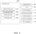
- the controller 200 functions as an identifying unit 210 and a collected-amount-estimating unit 220, and the details will be described later.
- the controller 200 can calculate the type of the refrigerant that is being collected, and a collected amount of the refrigerant that is being collected.
- the refrigerant channel 30 includes at least the expansion mechanism 40, the compressor 80, and the first heat exchanger 90.
- the refrigerant channel 30 includes, as an additional configuration, a second heat exchanger 50, an impurity separator 60, and a dryer 70 (see Fig. 1 ).
- the refrigerant channel 30 includes, as connection pipes, a first pipe 31, a second pipe 32, a third pipe 33, a fourth pipe 34, a fifth pipe 35, a sixth pipe 36, a suction pipe 811, and a discharge pipe 822 (see Fig. 1 ).
- the expansion mechanism 40 adjusts the pressure and flow rate of the refrigerant.
- the expansion mechanism 40 is, for example, a capillary tube.
- the expansion mechanism 40 is not limited to the capillary tube, and, for example, a mechanism generally used as an expansion mechanism in the refrigerant-collecting apparatus 100 may be appropriately selected.
- the refrigerant that has flowed from the first pipe 31 to the expansion mechanism 40 and has a pressure reduced by the expansion mechanism 40 flows to the second pipe 32.
- the refrigerant that has flowed to the second pipe 32 flows to the second heat exchanger 50.
- the second heat exchanger 50 is, for example, a heat exchanger having a double-pipe structure.
- the second heat exchanger 50 performs heat exchange between the refrigerant flowing from the second pipe 32 to the second heat exchanger 50, and the refrigerant flowing from the discharge pipe 822 to the second heat exchanger 50.
- the refrigerant flowing from the second pipe 32 to the second heat exchanger 50 performs heat exchange with the refrigerant flowing from the discharge pipe 822 to the second heat exchanger 50, and thus evaporates.
- the refrigerant that has evaporated in the second heat exchanger 50 flows to the third pipe 33.
- the refrigerant that has flowed to the third pipe 33 flows to the impurity separator 60.
- the second heat exchanger 50 may be a heat exchanger that performs heat exchange between the refrigerant and air. The details will be described later in a modification 1D.
- the impurity separator 60 separates, from the refrigerant, impurities (refrigerating-machine oil, dust, and the like) contained in the refrigerant.
- the impurity separator 60 separates impurities from the refrigerant by, for example, a gas-liquid separation scheme, but is not limited to the gas-liquid separation scheme.
- the impurity separator 60 may separate, from the refrigerant, impurities contained in the refrigerant by an electrostatic separation scheme.
- the impurity separator 60 includes an electrostatic precipitator for removing electrically-charged impurities.
- the refrigerant from which impurities have been separated by the impurity separator 60 flows to the fourth pipe 34.
- the refrigerant that has flowed to the fourth pipe 34 flows to the dryer 70.
- the dryer 70 removes, from the refrigerant, moisture contained in the refrigerant.
- the dryer 70 includes, for example, a tubular casing filled with a moisture adsorbent, such as alumina or silica gel.
- the refrigerant from which moisture has been removed by the dryer 70 flows to the suction pipe 811.
- the refrigerant that has flowed to the suction pipe 811 is sucked into the compressor 80.
- the compressor 80 sucks the refrigerant flowing through the suction pipe 811, compresses the sucked refrigerant with a compression mechanism (not shown), and discharges the compressed refrigerant to the discharge pipe 822.
- the compressor 80 has a suction opening 81 connected to the suction pipe 811.
- the compressor 80 also has a discharge opening 82 connected to the discharge pipe 822.
- the refrigerant-collecting apparatus 100 collects the refrigerant from the target equipment 10 by the suction force of the compressor 80.
- the refrigerant compressed by the compressor 80 is discharged to the discharge pipe 822 via the discharge opening 82.
- the refrigerant discharged to the discharge pipe 822 flows to the first heat exchanger 90 via the second heat exchanger 50 and the fifth pipe 35.
- the first heat exchanger 90 is a heat exchanger that functions as a refrigerant condenser.
- the first heat exchanger 90 performs heat exchange between the refrigerant flowing from the discharge pipe 822 to the first heat exchanger 90, and air sent from a fan 95 arranged near the first heat exchanger 90.
- the refrigerant flowing from the discharge pipe 822 to the first heat exchanger 90 performs heat exchange with the air, and thus condenses.
- the refrigerant that has condensed in the first heat exchanger 90 flows to the sixth pipe 36.
- the refrigerant that has flowed to the sixth pipe 36 flows to the container 110 via the second port 102, the second hose 22, and the second service port 110a.
- the refrigerant-collecting apparatus 100 includes the first sensor 11, the second sensor 12, the third sensor 13, the fourth sensor 14, and the fifth sensor 15.
- Each of the sensors 11, 12, 13, 14, and 15 is electrically connected to the controller 200. Values measured by each of the sensors 11, 12, 13, 14, and 15 are appropriately transmitted to the controller 200.
- the first sensor 11 is a sensor that measures a value relating to a first refrigerant temperature, which is a refrigerant temperature on the first-port-101 side.
- the "value relating to a first refrigerant temperature, which is a refrigerant temperature on the first-port-101 side" may be referred to as a "first value”.
- the first value is, for example, a temperature near the first port 101.
- the first sensor 11 is attached to, for example, the first pipe 31.
- the first sensor 11 is a thermistor.
- the second sensor 12 is a sensor that measures a value relating to a second refrigerant temperature, which is a refrigerant temperature on the second-port-102 side of the compressor 80.
- the "value relating to a second refrigerant temperature, which is a refrigerant temperature on the second-port side of the compressor 80" may be referred to as a "second value".
- the second value is, for example, a refrigerant temperature near the discharge opening 82 of the compressor 80.
- the second sensor 12 is attached to, for example, the discharge pipe 822.
- the second sensor 12 is a thermistor.
- the third sensor 13 is a sensor that measures a value relating to electric power consumed by the compressor 80.
- the "value relating to electric power consumed by the compressor 80" may be referred to as a "third value”.
- the "third value” is, for example, an electric-power value of the compressor 80.
- the third sensor 13 is attached to, for example, the compressor 80.
- the third sensor 13 is a wattmeter.
- the fourth sensor 14 is a sensor that measures the refrigerant temperature on the inlet side of the first heat exchanger 90 (condenser).
- the "refrigerant temperature on the inlet side of the first heat exchanger 90" may be referred to as a "fourth value”.
- the fourth sensor 14 is attached to, for example, the fifth pipe 35.
- the fourth sensor 14 is a thermistor.
- the fifth sensor 15 is a sensor that measures the suction temperature of the compressor 80.
- the "suction temperature of the compressor 80" may be referred to as a "fifth value”.
- the fifth sensor 15 is attached to, for example, the suction pipe 811.
- the fifth sensor 15 is a thermistor.
- the controller 200 is electrically connected to each unit of the refrigerant-collecting apparatus 100 in such a manner that control signals, information, and the like can be transmitted and received.
- the controller 200 is implemented by a computer.
- the controller 200 includes a control arithmetic device and a storage device.
- a processor such as a central processing unit (CPU) or a graphics processing unit (GPU)
- CPU central processing unit
- GPU graphics processing unit
- the control arithmetic device reads programs stored in the storage device, and performs predetermined arithmetic processing according to the programs.
- the control arithmetic device can write an arithmetic result into the storage device, and can read information stored in the storage device.
- the controller 200 has functions as the identifying unit 210, the collected-amount-estimating unit 220, and an updating unit 230. Further, a storage unit 300 of the controller 200 can be used as a database.
- the storage unit 300 includes the storage device, such as a read-only memory (ROM) and a random-access memory (RAM), of the controller 200.
- the storage unit 300 stores a program for controlling the workings of the refrigerant-collecting apparatus 100, a communication protocol used when the refrigerant-collecting apparatus 100 communicates with other equipment, and the like.
- the storage unit 300 also stores various data obtained by the inventor of the present application operating a test machine of the refrigerant-collecting apparatus 100 (which may be hereinafter simply referred to as the "test machine").
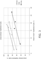
- the storage unit 300 stores some data corresponding to the information shown in the graph of Fig. 3 .
- the graph of Fig. 3 is created on the basis of various data obtained by making the test machine collect various types of refrigerants. More specifically, for each type of refrigerant, the level of the refrigerant temperature near the first port at the time when the test machine collects the refrigerant, and the level of the refrigerant temperature near the discharge opening of the compressor at the time when the test machine collects the refrigerant are measured to obtain some data.
- the graph of Fig. 3 is created. The horizontal axis of the graph of Fig.
- FIG. 3 indicates the level of the refrigerant temperature near the first port (described as “FIRST-PORT TEMPERATURE °C in Fig. 3 ").
- the vertical axis of the graph of Fig. 3 indicates the level of the refrigerant temperature near the discharge opening of the compressor (described as “DISCHARGE TEMPERATURE °C in Fig. 3 ").
- the level of the refrigerant temperature near the first port, and the level of the refrigerant temperature near the discharge opening of the compressor vary according to the type of the refrigerant. From this fact, the inventor of the present application has found that if the refrigerant temperature near the first port and the refrigerant temperature near the discharge opening are measured, the type of the refrigerant flowing through the refrigerant-collecting apparatus can be identified.
- the inventor of the present application has found that if a value relating to a first refrigerant temperature, which is the refrigerant temperature on the first-port side of the compressor, and a value relating to a second refrigerant temperature, which is the refrigerant temperature on the second-port side of the compressor are measured, the type of the refrigerant flowing through the refrigerant-collecting apparatus can be identified.
- Fig. 3 is a graph showing the data obtained by making the test machine collect R410A, R32, and R134a.
- the data stored in the storage unit 300 is not limited to the data relating to R410A, R32, and R134a.
- the storage unit 300 may store some data obtained by making the test machine collect R404A.
- the storage unit 300 may store some data obtained by making the test machine collect various types of refrigerants.
- the storage unit 300 stores some data corresponding to the information shown in the graph of Fig. 4 .
- the refrigerant temperature near the first port, the refrigerant temperature on the downstream side of the expansion mechanism, the saturation temperature of the refrigerant flowing through the suction side of the compressor (which may be hereinafter referred to as the "suction saturation temperature"), and the pressure of the refrigerant flowing through the suction side of the compressor are measured to obtain some data.
- the graph of Fig. 4 is created.
- the horizontal axis of the graph of Fig. 4 indicates the time period that has elapsed from the start of the operation of the test machine.
- the vertical axis on the left side of the graph of Fig. 4 indicates the level of the refrigerant temperature.
- the vertical axis on the right side of the graph of Fig. 4 indicates the level of the pressure of the refrigerant.
- the inventor of the present application has confirmed that the refrigerant is in a liquid state during a time slot indicated from a point A to a point B of the graph of Fig. 4 .
- the inventor of the present application also has confirmed that the refrigerant is in a gas state during a time slot indicated from the point B to a point C of the graph of Fig. 4 .
- the refrigerant temperature in a liquid state is generally stable, and the refrigerant temperature in a gas state is unstable. From this fact, the inventor of the present application has found that it is possible to easily determine whether a currently collected refrigerant is a refrigerant in a liquid state or a refrigerant in a gas state by measuring the refrigerant temperature of the refrigerant that is being collected by the refrigerant-collecting apparatus (for example, the refrigerant temperature near the first port).
- the behavior of the refrigerant temperature near the first port (see the dashed double-dotted line of Fig. 4 ), and the behavior of the suction saturation temperature (see the solid line of Fig. 4 ) are very similar.
- the inventor of the present application has found that a value corresponding to the suction saturation temperature can be calculated by correcting the refrigerant temperature near the first port with a predetermined correction value.
- the "value corresponding to the suction saturation temperature” may be referred to as the "first corrected measured value”.
- the "predetermined correction value” for calculating the first corrected measured value may be referred to as the "first correction value”.
- the storage unit 300 stores some data corresponding to the information shown in the graph of Fig. 5 .
- the refrigerant temperature on the inlet side of the condenser, the saturation temperature of the refrigerant flowing through the discharge side of the compressor (which may be hereinafter referred to as the "discharge saturation temperature"), and the pressure of the refrigerant flowing through the discharge side of the compressor are measured to obtain some data.
- the graph of Fig. 5 is created.
- the horizontal axis of the graph of Fig. 5 indicates the time period that has elapsed from the start of the operation of the test machine.
- the vertical axis on the left side of the graph of Fig. 5 indicates the level of the refrigerant temperature.
- the vertical axis on the right side of the graph of Fig. 5 indicates the level of the pressure of the refrigerant. Note that the inventor of the present application has confirmed that the refrigerant is in a liquid state during a time slot indicated from a point A to a point B of the graph of Fig. 5 . The inventor of the present application also has confirmed that the refrigerant is in a gas state during a time slot indicated from the point B to a point C of the graph of Fig. 5 .
- the behavior of the refrigerant temperature on the inlet side of the condenser (see the dashed double-dotted line of Fig. 5 ), and the behavior of the discharge saturation temperature (see the solid line of Fig. 5 ) are very similar.
- the inventor of the present application has found that a value corresponding to the discharge saturation temperature can be calculated by correcting the refrigerant temperature on the inlet side of the condenser with a predetermined correction value.
- the "value corresponding to the discharge saturation temperature” may be referred to as the "third corrected measured value”.
- the "predetermined correction value” for calculating the third corrected measured value may be referred to as the "third correction value”.
- the identifying unit 210 identifies the type of refrigerant flowing through the refrigerant channel 30.
- the identifying unit 210 identifies the type of the refrigerant on the basis of a first value measured by the first sensor 11, a second value measured by the second sensor 12, and various data stored in the storage unit 300.
- the identifying unit 210 refers to the data stored in the storage unit 300 (data corresponding to the information shown in the graph of Fig. 3 ), and thus identifies the type of the refrigerant as R134a.
- the identifying unit 210 refers to the data stored in the storage unit 300 (data corresponding to the information shown in the graph of Fig. 3 ), and thus identifies the type of the refrigerant as R410A.
- the identifying unit 210 identifies the type of the refrigerant collected by the refrigerant-collecting apparatus 100.
- This configuration eliminates a possibility that the collection worker makes a recognition mistake or a recording mistake when the type of the collected refrigerant is identified. Therefore, the type of the refrigerant collected by the refrigerant-collecting apparatus 100 can be identified without a mistake. Since the type of the refrigerant collected by the refrigerant-collecting apparatus 100 is identified without a mistake, it is easy to manage the refrigerant collected by the refrigerant-collecting apparatus 100.
- the type of the collected refrigerant is identified on the basis of a value measured by the first sensor 11 and a value measured by the second sensor 12.
- the first sensor 11 and the second sensor 12 are thermistors.
- the refrigerant-collecting apparatus 100 according to the present embodiment can identify the type of the refrigerant with a relatively inexpensive configuration.
- the collected-amount-estimating unit 220 estimates a collected amount of the refrigerant collected from the target equipment 10 by the refrigerant-collecting apparatus 100.
- the collection of the refrigerant by the refrigerant-collecting apparatus 100 includes a liquid collection state, which is a state in which the refrigerant in a liquid state is collected, and a gas collection state, which is a state in which the refrigerant in a gas state is collected.
- the collected-amount-estimating unit 220 totals a collected amount of the refrigerant in the liquid collection state (which may be hereinafter referred to as the collected-liquid amount), and the collected amount of the refrigerant in the gas collection state (which may be hereinafter referred to as the collected-gas amount) to estimate a collected amount of the refrigerant collected by the refrigerant-collecting apparatus 100.
- the estimation of the collected-liquid amount and the estimation of the collected-gas amount by the collected-amount-estimating unit 220 will be each described in order.
- the collected-amount-estimating unit 220 Before the collected-amount-estimating unit 220 starts estimation of a collected-liquid amount, the collected-amount-estimating unit 220 refers to a first value measured by the first sensor 11. As described above, the first value measured by the first sensor 11 is referred to determine whether a currently collected refrigerant is a liquid refrigerant or a gas refrigerant. The collected-amount-estimating unit 220 that has referred to the first value, and thus confirmed that the state of the currently collected refrigerant is a liquid state determines that the current operation is in the liquid collection state. The collected-amount-estimating unit 220 that has determined that the current operation is in the liquid collection state starts estimation of a collected-liquid amount.
- the collected-liquid amount can be estimated by integrating the flow rate of the refrigerant in a liquid state flowing through the refrigerant channel 30 over the operation time period in the liquid collection state. Note that the operation time period in the liquid collection state can be measured by a timer or the like (not shown).
- the flow rate G of the refrigerant in a liquid state flowing through the refrigerant channel 30 can be derived from the following Expression 1.
- G W ⁇ ⁇ / ⁇ H _ comp
- the electric-power value W is measured as a third value by the third sensor 13. Therefore, when the collected-amount-estimating unit 220 estimates a collected-liquid amount, the collected-amount-estimating unit 220 communicates with the third sensor 13 to refer to a third value.
- the compressor efficiency ⁇ can be calculated from the type of the refrigerant identified by the identifying unit 210, and a first value. Therefore, when the collected-amount-estimating unit 220 estimates a collected-liquid amount, the collected-amount-estimating unit 220 communicates with the identifying unit 210 and the first sensor 11 to refer to the type of the refrigerant and a first value.
- the enthalpy difference ⁇ H_comp can be obtained by subtracting the enthalpy on the suction side of the compressor 80 from the enthalpy on the discharge side of the compressor 80.
- the enthalpy on the discharge side of the compressor 80 can be obtained from the refrigerant temperature near the discharge opening 82 of the compressor 80 and a discharge saturation pressure.
- the refrigerant temperature near the discharge opening 82 of the compressor 80 is measured as a second value by the second sensor 12.
- the discharge saturation pressure can be calculated from the type of the refrigerant flowing through the refrigerant channel 30 and the discharge saturation temperature.
- the type of the refrigerant flowing through the refrigerant channel 30 is identified by the identifying unit 210.
- a value corresponding to the discharge saturation temperature (third corrected measured value) can be calculated by correcting the refrigerant temperature on the inlet side of the condenser with the third correction value.
- the refrigerant temperature on the inlet side of the condenser is measured as a fourth value by the fourth sensor 14.
- the collected-amount-estimating unit 220 estimates a collected-liquid amount
- the collected-amount-estimating unit 220 communicates with the second sensor 12, the fourth sensor 14, and the identifying unit 210 to refer to the second value, the fourth value, and the type of the refrigerant.
- the collected-amount-estimating unit 220 that has referred to the fourth value corrects the fourth value with the third correction value to calculate a third corrected measured value.
- the collected-amount-estimating unit 220 that has calculated the third corrected measured value computes a discharge saturation pressure on the basis of the third corrected measured value and the type of the refrigerant identified by the identifying unit 210.
- the collected-amount-estimating unit 220 that has calculated the discharge saturation pressure calculates the enthalpy on the discharge side of the compressor 80 on the basis of the discharge saturation pressure and the second value (the refrigerant temperature near the discharge opening 82 of the compressor 80).
- the enthalpy on the suction side of the compressor 80 can be obtained from the suction temperature of the compressor 80 and a suction saturation pressure.
- the suction temperature of the compressor 80 is measured as a fifth value by the fifth sensor 15.
- the suction saturation pressure can be calculated from the type of the refrigerant flowing through the refrigerant channel 30, and the suction saturation temperature.
- the type of the refrigerant flowing through the refrigerant channel 30 is identified by the identifying unit 210.
- a value corresponding to the suction saturation temperature (first corrected measured value) can be calculated by correcting the refrigerant temperature near the first port 101 with the first correction value.
- the refrigerant temperature near the first port 101 is measured as a first value by the first sensor 11.
- the collected-amount-estimating unit 220 estimates a collected-liquid amount
- the collected-amount-estimating unit 220 communicates with the first sensor 11, the fifth sensor 15, and the identifying unit 210 to refer to the first value, the fifth value, and the type of the refrigerant.
- the collected-amount-estimating unit 220 that has referred to the first value corrects the first value with the first correction value to calculate a first corrected measured value.
- the collected-amount-estimating unit 220 that has calculated the first corrected measured value computes a suction saturation pressure on the basis of the first corrected measured value and the type of the refrigerant identified by the identifying unit 210.
- the collected-amount-estimating unit 220 that has calculated the suction saturation pressure calculates the enthalpy on the suction side of the compressor 80 on the basis of the suction saturation pressure and the fifth value (the suction temperature of the compressor 80).
- the collected-amount-estimating unit 220 that has calculated the enthalpy on the discharge side of the compressor 80 and the enthalpy on the suction side of the compressor 80 subtracts the enthalpy on the suction side of the compressor 80 from the enthalpy on the discharge side of the compressor 80 to calculate ⁇ H_comp.
- the collected-amount-estimating unit 220 that has referred to or calculated each of the electric-power value W, the compressor efficiency ⁇ , and ⁇ H_comp computes Expression 1 described above to calculate the flow rate G of the refrigerant in a liquid state flowing through the refrigerant channel 30. Then the collected-amount-estimating unit 220 integrates the flow rate G of the refrigerant in a liquid state over the operation time period in the liquid collection state measured by the timer or the like (not shown) to estimate a collected-liquid amount.
- the collected-amount-estimating unit 220 Before the collected-amount-estimating unit 220 starts estimation of a collected-gas amount, the collected-amount-estimating unit 220 refers to a first value measured by the first sensor 11. As described above, the first value measured by the first sensor 11 is referred to determine whether a currently collected refrigerant is a liquid refrigerant or a gas refrigerant. The collected-amount-estimating unit 220 that has referred to the first value, and thus confirmed that the state of the currently collected refrigerant is a gas state determines that the current operation is in the gas collection state. The collected-amount-estimating unit 220 that has determined that the current operation is in the gas collection state starts estimation of a collected-gas amount.
- the inventor of the present application has found that the collected-gas amount can be calculated by multiplying a collected-liquid amount by a predetermined estimation parameter.
- the predetermined estimation parameter for estimating a collected amount of the refrigerant in a gas state is 10%. Therefore, the collected-amount-estimating unit 220 multiplies a collected-liquid amount estimated in (4-3-1) described above by 1/10 to estimate a collected-gas amount. Note that the estimation parameter is stored in a predetermined storage area of the storage unit 300.
- the collected-amount-estimating unit 220 that has estimated a collected-liquid amount of the refrigerant and a collected-gas amount of the refrigerant totals the collected-liquid amount and the collected-gas amount.
- the collected-amount-estimating unit 220 estimates, as a collected amount of the refrigerant, a numerical value calculated by totaling the collected-liquid amount and the collected-gas amount.
- the collected-amount-estimating unit 220 estimates a collected amount of the refrigerant collected by the refrigerant-collecting apparatus 100.
- This configuration estimates a collected amount of the refrigerant collected by the refrigerant-collecting apparatus 100, in addition to the type of the refrigerant collected by the refrigerant-collecting apparatus 100. Therefore, the refrigerant-collecting apparatus 100 according to the present embodiment makes it easier to manage the refrigerant collected by the refrigerant-collecting apparatus 100.
- a collected amount of the collected refrigerant is identified on the basis of values measured by the first sensor 11, the second sensor 12, the third sensor 13, the fourth sensor 14, and the fifth sensor 15.
- the first sensor 11, the second sensor 12, the fourth sensor 14, and the fifth sensor 15 are thermistors.
- the third sensor 13 is a wattmeter.
- the type of the refrigerant identified by the identifying unit 210 and the collected amount of the refrigerant estimated by the collected-amount-estimating unit 220 are stored in the storage unit 300.
- the storage unit 300 stores the type of the refrigerant, and the collected amount of the refrigerant that are associated with each other. This configuration makes it easier to manage the refrigerant collected by the refrigerant-collecting apparatus 100.
- the type of the refrigerant and the collected amount of the refrigerant stored in the storage unit 300 may be transmitted to a management apparatus, a server, or the like (not shown) through a communication network (not shown).
- the controller 200 may have a function for calculating, from the type of the refrigerant and the collected amount of the refrigerant that are associated with each other and stored in the storage unit 300, the CO2 amount of the collected-refrigerant amount.
- the CO2 amount of the collected-refrigerant amount can be calculated by multiplying the collected amount of the refrigerant by the global warming potential (GWP) of the type of the refrigerant. Therefore, for example, after the refrigerant collection work ends, the controller 200 may multiply the collected amount of the refrigerant by the global warming potential (GWP) of the type of the refrigerant to calculate the CO2 amount of the collected-refrigerant amount. Note that in a case where the controller 200 has a function for calculating the CO2 amount of the collected-refrigerant amount, the storage unit 300 stores the global warming potential (GWP) for each type of refrigerant.
- GWP global warming potential
- the refrigerant-collecting apparatus 100 includes the first port 101, the second port 102, the refrigerant channel 30, and the identifying unit 210.
- the first port 101 is connected to the target equipment 10 from which a refrigerant is collected.
- the second port 102 is connected to the container 110 in which the refrigerant collected from the target equipment 10 is put.
- the refrigerant channel 30 connects the first port 101 and the second port 102.
- the refrigerant channel 30 includes at least the expansion mechanism 40, the compressor 80, and the heat exchanger 90.
- the identifying unit 210 identifies the type of the refrigerant that is being collected from the target equipment 10.
- the identifying unit 210 identifies the type of the refrigerant that is being collected from the target equipment 10.
- the first value relates to a first refrigerant temperature, which is the refrigerant temperature on the first-port-101 side of the compressor 80.
- the second value relates to a second refrigerant temperature, which is the refrigerant temperature on the second-port-102 side of the compressor 80.
- the identifying unit 210 identifies the type of the refrigerant that is being collected from the target equipment 10. This configuration eliminates a possibility that the collection worker makes a recognition mistake or a recording mistake. Therefore, the refrigerant-collecting apparatus 100 according to the present embodiment can identify the type of the collected refrigerant without a mistake. Since the type of the collected refrigerant is identified without a mistake, it is easy to manage the collected refrigerant.
- the first value is the refrigerant temperature near the first port 101.
- the refrigerant temperature near the first port 101 is employed as the first value.
- the refrigerant temperature near the first port 101 can be measured by a relatively inexpensive sensor. Therefore, the refrigerant-collecting apparatus 100 according to the present embodiment can reduce the manufacturing cost of the refrigerant-collecting apparatus 100.
- the heat exchanger 90 is a condenser that condenses the refrigerant.
- the second value is the refrigerant temperature near the discharge opening 82 of the compressor 80.
- the refrigerant temperature near the discharge opening 82 of the compressor 80 is employed as the second value.
- the refrigerant temperature near the discharge opening 82 of the compressor 80 can be measured by a relatively inexpensive sensor. Therefore, the refrigerant-collecting apparatus 100 according to the present embodiment can reduce the manufacturing cost of the refrigerant-collecting apparatus 100.
- the third value is an electric-power value of the compressor 80.
- the electric-power value of the compressor 80 is employed as the third value.
- the electric-power value of the compressor 80 can be measured by a relatively inexpensive sensor. Therefore, the refrigerant-collecting apparatus 100 according to the present embodiment can reduce the manufacturing cost of the refrigerant-collecting apparatus 100.
- the refrigerant-collecting apparatus 100 further includes the collected-amount-estimating unit 220.
- the collected-amount-estimating unit 220 estimates a collected amount of the refrigerant collected from the target equipment 10.
- the collected-amount-estimating unit 220 estimates a collected amount of the refrigerant.
- This configuration estimates a collected amount of the collected refrigerant, in addition to the type of the collected refrigerant. Therefore, the refrigerant-collecting apparatus 100 according to the present embodiment makes it easier to manage the collected refrigerant.
- the refrigerant-collecting apparatus 100 further includes the storage unit.
- the storage unit stores the type of the refrigerant identified by the identifying unit 210, and a collected amount of the refrigerant estimated by the collected-amount-estimating unit 220 that are associated with each other.
- the collection worker confuses the collected amount of the refrigerant collected from a first one of the target equipment with the collected amount of the refrigerant collected from a second one of the target equipment.
- the storage unit 300 stores the type of the refrigerant, and the collected amount of the refrigerant that are associated with each other. Therefore, the refrigerant-collecting apparatus 100 according to the present embodiment makes it easier to manage the collected refrigerant.
- the collected-amount-estimating unit 220 estimates a collected-liquid amount and a collected-gas amount of the refrigerant, respectively, to estimate a collected amount of the refrigerant.
- the collected-amount-estimating unit 220 determines the liquid collection state on the basis of the refrigerant temperature near the first port 101.
- the refrigerant temperature near the first port 101 can be measured by a relatively inexpensive sensor. Therefore, the refrigerant-collecting apparatus 100 according to the present embodiment can reduce the manufacturing cost of the refrigerant-collecting apparatus 100.
- the collected-amount-estimating unit 220 computes the suction saturation pressure using the first corrected measured value obtained by correcting the refrigerant temperature near the first port 101.
- the collected-amount-estimating unit 220 computes the discharge saturation pressure using the third corrected measured value obtained by correcting the refrigerant temperature near the heat exchanger 90.
- the collected-amount-estimating unit 220 computes the suction saturation pressure using the first corrected measured value obtained by correcting the refrigerant temperature near the first port 101. Therefore, the suction saturation pressure can be calculated without the provision of a relatively expensive sensor, such as a pressure sensor.
- the collected-amount-estimating unit 220 computes the discharge saturation pressure using the third corrected measured value obtained by correcting the refrigerant temperature near the heat exchanger 90. Therefore, the discharge saturation pressure can be calculated without the provision of a relatively expensive sensor, such as a pressure sensor. Therefore, the refrigerant-collecting apparatus 100 according to the present embodiment can reduce the manufacturing cost of the refrigerant-collecting apparatus 100.
- the collected-amount-estimating unit 220 estimates a collected-liquid amount on the basis of the compressor efficiency of the compressor 80, the third value, the suction saturation pressure, and the discharge saturation pressure in a liquid collection operation for collecting the refrigerant in a liquid state.
- the collected-amount-estimating unit 220 estimates a collected-liquid amount on the basis of the compressor efficiency of the compressor 80, the third value, the suction saturation pressure, and the discharge saturation pressure.
- the compressor efficiency can be calculated from the type of the refrigerant and the first value.
- the third value can be measured by a relatively inexpensive sensor.
- the suction saturation pressure can be computed using the first corrected measured value obtained by correcting the refrigerant temperature near the first port 101.
- the discharge saturation pressure can be computed using the third corrected measured value obtained by correcting the refrigerant temperature near the heat exchanger 90. Therefore, the refrigerant-collecting apparatus 100 according to the present embodiment can reduce the manufacturing cost of the refrigerant-collecting apparatus 100.
- the collected-amount-estimating unit 220 estimates a collected-gas amount on the basis of the operation time period in a gas collection operation for collecting the refrigerant in a gas state.
- the collected-amount-estimating unit 220 estimates a collected-gas amount on the basis of a collected-liquid amount.
- the refrigerant channel 30 further includes the impurity separator 60.
- the separation scheme of the impurity separator is a gas-liquid separation scheme or an electrostatic separation scheme.
- a refrigerant collected from the target equipment 10 is R32, R410A, R134a, or R404A.
- the target equipment 10 is not limited to the air-conditioning apparatus.
- the target equipment 10 may be, for example, a refrigerator, a freezer, a water heater, or the like.
- the refrigerant temperature near the first port 101 is measured as the first value.
- examples of the first value are not limited to this example.
- the inventor of the present application has found that if a value relating to a first refrigerant temperature, which is the refrigerant temperature on the first-port side of the compressor, and a value relating to a second refrigerant temperature, which is the refrigerant temperature on the second-port side of the compressor are measured, the type of the refrigerant flowing through the refrigerant-collecting apparatus can be identified. Therefore, for example, the first value may be an outside-air temperature or a refrigerant temperature near the suction opening 81 of the compressor 80.
- an outside-air temperature is employed as the first value will be described as an example.
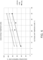
- the refrigerant-collecting apparatus 100 includes a sensor that can detect an outside-air temperature, in addition to the first sensor 11 or instead of the first sensor 11. Further, in a case where an outside-air temperature is employed as the first value, the storage unit 300 of the refrigerant-collecting apparatus 100 stores some data corresponding to the information shown in the graph of Fig. 6 .
- the graph of Fig. 6 is created on the basis of some data obtained by making the test machine collect various types of refrigerants.
- the level of an outside-air temperature at the time when the test machine collects the refrigerant, and the level of the refrigerant temperature near the discharge opening of the compressor at the time when the test machine collects the refrigerant are measured to obtain some data.
- the graph of Fig. 6 is created.
- the horizontal axis of the graph of Fig. 6 indicates the level of the outside-air temperature (described as "OUTSIDE-AIR TEMPERATURE °C in Fig. 6 ").
- the vertical axis of the graph of Fig. 6 indicates the level of the refrigerant temperature near the discharge opening of the compressor (described as "DISCHARGE TEMPERATURE °C in Fig. 6 ").
- the identifying unit 210 can identify the type of the refrigerant on the basis of the data stored in the storage unit 300 (data corresponding to the information shown in the graph of Fig. 6 ). For example, suppose a situation where as a result of the measurement by the sensor that detects an outside-air temperature and the second sensor 12, it has been determined that the first value is 21°C and the second value is 91°C. In this case, the identifying unit 210 refers to the data stored in the storage unit 300 (data corresponding to the information shown in the graph of Fig. 6 ), and thus identifies the type of the refrigerant as R32.
- the identifying unit 210 identifies the type of the refrigerant on the basis of the first value and the second value.
- methods for the identification by the identifying unit 210 are not limited to this example, and, for example, the identifying unit 210 may identify the type of the refrigerant on the basis of the first value and the third value.
- the storage unit 300 stores some data corresponding to the information shown in the graph of Fig. 7 .
- the graph of Fig. 7 is created on the basis of some data obtained by making the test machine collect various types of refrigerants. More specifically, for each type of refrigerant, the level of the refrigerant temperature near the first port at the time when the test machine collects the refrigerant, and the level of the electric-power value of the compressor at the time when the test machine collects the refrigerant are measured to obtain some data. On the basis of the data, the graph of Fig. 7 is created. The horizontal axis of the graph of Fig.
- FIG. 7 indicates the level of the refrigerant temperature near the first port (described as “SUCTION PORT TEMPERATURE °C” in Fig. 7 ).
- the vertical axis of the graph of Fig. 7 indicates the level of the electric-power value of the compressor (described as "COMPRESSOR ELECTRIC-POWER W" in Fig. 7 ).
- the level of the refrigerant temperature near the first port, and the level of the electric-power value of the compressor vary according to the type of the refrigerant. From this fact, the inventor of the present application has found that if the refrigerant temperature near the first port and the electric-power value of the compressor are measured, the type of the refrigerant flowing through the refrigerant-collecting apparatus can be identified.
- the inventor of the present application has found that if a value relating to a first refrigerant temperature, which is the refrigerant temperature on the first-port side of the compressor, and a value relating to the electric power consumed by the compressor are measured, the type of the refrigerant flowing through the refrigerant-collecting apparatus can be identified.
- the identifying unit 210 can identify the type of the refrigerant on the basis of the first value, the third value, and the data stored in the storage unit 300 and corresponding to the information shown in the graph of Fig. 7 .
- the storage unit 300 stores some data corresponding to the information shown in the graph of Fig. 8 .
- the graph of Fig. 8 is created on the basis of some data obtained by making the test machine collect various types of refrigerants. More specifically, for each type of refrigerant, the level of an outside-air temperature at the time when the test machine collects the refrigerant, and the level of the electric-power value of the compressor at the time when the test machine collects the refrigerant are measured to obtain some data. On the basis of the data, the graph of Fig. 8 is created. The horizontal axis of the graph of Fig.
- the identifying unit 210 can identify the type of the refrigerant on the basis of the first value, the third value, and the data stored in the storage unit 300 and corresponding to the information shown in the graph of Fig. 8 .
- the identifying unit 210 may identify the type of the refrigerant on the basis of the first value, the second value, and the third value. In this case, for example, the identifying unit 210 may identify the type of the refrigerant on the basis of the first value, the second value, and some data corresponding to the information shown in the graph of Fig. 6 , and then may identify the type of the refrigerant on the basis of the first value, the third value, and some data corresponding to the information shown in the data of Fig. 7 . Since this configuration confirms the type of the refrigerant twice, this configuration can precisely identify the type of the refrigerant.
- the refrigerant-collecting apparatus 100 includes the second heat exchanger 50 that performs heat exchange between the refrigerant flowing from the second pipe 32 to the second heat exchanger 50, and the refrigerant flowing from the discharge pipe 822 to the second heat exchanger 50.
- the configuration of the second heat exchanger 50 is not limited to this example.
- the second heat exchanger 50 may be an evaporator that performs heat exchange between the refrigerant flowing from the second pipe 32 to the second heat exchanger 50, and air sent to the second heat exchanger 50 by a fan (not shown) (see Fig. 9 ).
- the refrigerant flowing through the discharge pipe 822 does not flow to the second heat exchanger 50. Therefore, in the refrigerant-collecting apparatus 100 according to the modification 1D, the temperature variation of the refrigerant flowing through the discharge pipe 822 is suppressed.
- the refrigerant temperature of the refrigerant flowing through the discharge pipe 822 is substantially the same as the refrigerant temperature of the refrigerant flowing through the inlet side of the first heat exchanger 90 (condenser). Therefore, for example, for the refrigerant-collecting apparatus 100 according to the modification 1D, the refrigerant temperature near the first heat exchanger 90 (condenser) measured by the fourth sensor 14 may be used as the second value. In other words, for example, the fourth sensor 14 may also function as the second sensor 12. In this case, as shown in Fig. 9 , it is not necessary to attach the second sensor 12 to the refrigerant-collecting apparatus 100. Therefore, the refrigerant-collecting apparatus 100 according to the modification 1D can reduce the number of assembly steps of the refrigerant-collecting apparatus 100.
- the temperature measured by the second sensor 12 may be used as the refrigerant temperature near the first heat exchanger 90 (condenser).
- the second sensor 12 may also function as the fourth sensor 14. In this case, although not shown, it is not necessary to attach the fourth sensor 14 to the refrigerant-collecting apparatus 100.
- the first heat exchanger 90 and the second heat exchanger 50 may share a fan.
- the arrangement position of each equipment may be adjusted such that the air sent from the fan 95 passes through the first heat exchanger 90, and then flows to the second heat exchanger 50.
- the electric-power value of the compressor 80 is measured as the third value.
- the third value may be, for example, the electric-current value of the compressor 80.
- the refrigerant-collecting apparatus 100 includes, as the third sensor, an ammeter instead of the wattmeter.
- the controller 200 performs a predetermined computation on the electric-current value measured by the third sensor 13.
- the refrigerant-collecting apparatus 100 may include a sensor that measures the refrigerant temperature on the downstream side of the expansion mechanism 40, and the collected-amount-estimating unit 220 may determine the liquid collection state on the basis of the refrigerant temperature on the downstream side of the expansion mechanism 40.
- the sensor that measures the refrigerant temperature on the downstream side of the expansion mechanism 40 is arranged at, for example, the second pipe 32.
- the refrigerant-collecting apparatus 100 may include a sensor that measures the refrigerant temperature on the downstream side of the expansion mechanism 40, and the collected-amount-estimating unit 220 may compute the suction saturation pressure using a second corrected measured value obtained by correcting the refrigerant temperature on the downstream side of the expansion mechanism with a predetermined correction value (second correction value).
- the sensor that measures the refrigerant temperature on the downstream side of the expansion mechanism 40 is arranged at, for example, the second pipe 32.
- the collected-amount-estimating unit 220 estimates a collected-gas amount by multiplying a collected-liquid amount by a predetermined estimation parameter.
- methods in which the collected-amount-estimating unit 220 estimates a collected-gas amount are not limited to this example.
- the storage unit 300 may store a data set in which an operation time period in the gas collection state and a collected-gas amount are associated with each other.
- the collected-amount-estimating unit 220 may measure an operation time period in the gas collection state with a timer (not shown).
- the collected-amount-estimating unit 220 may refer to an operation time period in the gas collection state measured by the timer (not shown), and a data set in question to estimate a collected-gas amount.
- the controller 200 may have a function as an updating unit 230 although the description is omitted in the embodiment described above.
- the updating unit 230 updates at least one of the first correction value, the second correction value, the third correction value, the compressor efficiency, and the estimation parameter in, for example, the following manner.
- the collected-refrigerant amount actually measured by the collection worker is recorded in the storage unit 300.
- the storage unit 300 of the refrigerant-collecting apparatus 100 according to the modification 1I stores the electric-power value of the compressor 80, the first value, the fourth value, and the operation time period in the liquid collection state that are associated with the actually-measured collected-refrigerant amount.
- the storage unit 300 of the refrigerant-collecting apparatus 100 according to the modification 1I stores a predetermined estimation formula for estimating an estimated value of a collected-refrigerant amount from the electric-power value of the compressors 80, the first value, the fourth value, and the operation time period in the liquid collection state.
- the parameters of the predetermined estimation formula are the first correction value, the third correction value, the estimation parameter, and the compressor efficiency.
- the updating unit 230 calculates, as an optimization problem, the parameters (the first correction value, the third correction value, the estimation parameter, and the compressor efficiency) such that the mean square error between actually-measured values of collected-refrigerant amounts and estimated values of the collected-refrigerant amounts is minimized, and updates the parameters.
- Used for the optimization is, for example, the method of steepest descent or Newton's method. In this way, every time a predetermined amount of data is accumulated, the values of the first correction value, the third correction value, the compressor efficiency, and the estimation parameter are updated to improve the estimation precision of the collected-refrigerant amount.
- the updating unit 230 updates the second correction value, the third correction value, the estimation parameter, and the compressor efficiency.
- the identifying unit 210 identifies the types of refrigerants that are fluorocarbon-based refrigerants.
- the types of refrigerants that can be identified by the identifying unit 210 are not limited to fluorocarbon-based refrigerants, and the identifying unit 210 can identify various types of refrigerants.
- the collected-amount-estimating unit 220 can estimate the collected amounts of various types of refrigerants.
- the identifying unit 210 of the refrigerant-collecting apparatus 100 identifies the type of the refrigerant.
- the configuration of the identifying unit 210 is not limited to this example, and, for example, part of the function as the identifying unit 210 may be implemented by a server or the like (not shown).
- the refrigerant-collecting apparatus 100 may transmit the first value and the second value to a server having part of the function as the identifying unit 210, with communication equipment (not shown).
- the result of a computation performed in the server may be transmitted to the refrigerant-collecting apparatus 100.
- the result of the computation performed in the server may be transmitted to a mobile terminal or the like of the collection worker.
- the identified type of the refrigerant may be transmitted to a smartphone, a tablet, or the like of the collection worker.
- part of the function as the collected-amount-estimating unit 220 may be implemented by a server or the like (not shown).
- the refrigerant-collecting apparatus 100 may transmit the first value, the second value, the third value, the fourth value, and the fifth value to a server having part of the function as the identifying unit 210, with communication equipment (not shown).
- the result of a computation performed in the server may be transmitted to the refrigerant-collecting apparatus 100.
- the result of the computation performed in the server may be transmitted to a mobile terminal or the like of the collection worker.
- the estimated collected-refrigerant amount may be transmitted to a smartphone, a tablet, or the like of the collection worker.
- thermocouples examples of the first sensor 11, the second sensor 12, the fourth sensor 14, and the fifth sensor 15 are not limited to this example, and may be, for example, thermocouples.
- sensors that can measure the temperature of the refrigerant and can be obtained at relatively low cost may be appropriately selected.
- a controller 200S is electrically connected to each unit of the refrigerant-collecting apparatus 100S in such a manner that control signals, information, and the like can be transmitted and received.
- the controller 200S is implemented by a computer.
- the controller 200S includes a control arithmetic device and a storage device.
- a control arithmetic device a processor, such as a CPU or a GPU, can be used.
- the control arithmetic device reads programs stored in the storage device, and performs predetermined arithmetic processing according to the programs.
- the control arithmetic device can write an arithmetic result into the storage device, and can read information stored in the storage device.
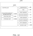
- the controller 200S has functions as a collected-amount-estimating unit 220S, an updating unit 230, and a storage unit 300S . Further, the storage unit 300S of the controller 200S can be used as a database.
- the storage unit 300S includes the storage device, such as a ROM and a RAM, of the controller 200S.
- the storage unit 300S stores a program for controlling the workings of the refrigerant-collecting apparatus 100S, a communication protocol used when the refrigerant-collecting apparatus 100S communicates with other equipment, and the like.
- the storage unit 300S also stores various data obtained by the inventor of the present application operating a test machine of the refrigerant-collecting apparatus 100S (which may be hereinafter simply referred to as the "test machine").
- the storage unit 300S stores a data set in which an operation time period in a liquid collection state and a collected-liquid amount are associated with each other.
- the storage unit 300S also stores a data set in which an operation time period in a gas collection state and a collected-gas amount are associated with each other.
- the collected-amount-estimating unit 220S refers to an operation time period in the liquid collection state measured by a timer (not shown), an operation time period in the gas collection state measured by the timer (not shown), and various data sets stored in the storage unit 300S to estimate the collected-liquid amount and the collected-gas amount.
- the refrigerant-collecting apparatus 100S includes the output unit 240.
- the output unit 240 is, for example, a liquid crystal display, and can appropriately display a collected-refrigerant amount estimated by the collected-amount-estimating unit 220S. Note that, for example, the output unit 240 may display various information, such as values measured by various sensors.
- the refrigerant-collecting apparatus 100S includes a first port 101, a second port 102, a refrigerant channel 30, the collected-amount-estimating unit 220S, and the output unit 240.
- the first port 101 is connected to target equipment 10 from which a refrigerant is collected.
- the second port 102 is connected to a container 110 in which the refrigerant collected from the target equipment 10 is put.
- the refrigerant channel 30 connects the first port 101 and the second port 102.
- the refrigerant channel 30 includes at least an expansion mechanism 40, a compressor 80, and a heat exchanger 90.
- the collected-amount-estimating unit 220S estimates a collected amount of the refrigerant collected from the target equipment 10.
- the output unit 240 outputs the result estimated by the collected-amount-estimating unit 220S.
- the collected-amount-estimating unit 220S estimates a collected amount of the refrigerant collected from the target equipment 10. This configuration eliminates a possibility that the collection worker makes a recognition mistake or a recording mistake. Therefore, the refrigerant-collecting apparatus 100S according to the present embodiment can identify the collected amount of the collected refrigerant without a mistake. Since the type of the collected refrigerant is identified without a mistake, it is easy to manage the collected refrigerant.
- the present disclosure is not limited to each of the embodiments described above.
- the present disclosure can be embodied by modifying the components without departing from the gist of the present disclosure in an implementation stage.
- the present disclosure can form various disclosures by appropriate combination of a plurality of components disclosed in each of the embodiments described above. For example, some components may be eliminated from all the components shown in the embodiment.
- components may be appropriately combined with the different embodiment. Therefore, it should be considered that the present embodiments are only examples in all respects and are not limiting. Thus, it is intended that the present embodiments include all revisions obvious to those skilled in the art.
Landscapes
- Engineering & Computer Science (AREA)
- Physics & Mathematics (AREA)
- Mechanical Engineering (AREA)
- Thermal Sciences (AREA)
- General Engineering & Computer Science (AREA)
- Air Conditioning Control Device (AREA)
Abstract
Description
- The present disclosure relates to a refrigerant-collecting apparatus.
- In some cases, refrigerant-collecting apparatuses have been used to collect a used refrigerant from refrigeration apparatuses and the like. Further, as disclosed in PTL 1 (
WO 2020/003509 ), management systems that manage information relating to the collected refrigerant have been known. In the management system described inPTL 1 describe above, a collection worker who has performed refrigerant collection work transmits, to a management apparatus, information relating to the collected refrigerant. As disclosed inPTL 1 described above, the information transmitted to the management apparatus by the collection worker includes information relating to the type of the collected refrigerant. - It is conceivable that in a case where a collection worker transmits, to a management apparatus, information relating to the type of a collected refrigerant, the collection worker identifies the type of the collected refrigerant. However, when the collection worker identifies the type of the collected refrigerant, there is a possibility that the collection worker makes a recognition mistake or a recording mistake. In a case where due to the recognition mistake or the recording mistake of the collection worker, information that a refrigerant of a type different from the original type has been collected is transmitted to the management apparatus, it becomes difficult to manage the collected refrigerant.
- A refrigerant-collecting apparatus according to a first aspect includes a first port, a second port, a refrigerant channel, and an identifying unit. The first port is connected to target equipment from which a refrigerant is collected. The second port is connected to a container in which the refrigerant collected from the target equipment is put. The refrigerant channel connects the first port and the second port. The refrigerant channel includes at least an expansion mechanism, a compressor, and a heat exchanger. The identifying unit identifies the type of the refrigerant that is being collected from the target equipment. On the basis of a first value and a second value, the identifying unit identifies the type of the refrigerant that is being collected from the target equipment. Alternatively, on the basis of the first value and a third value, the identifying unit identifies the type of the refrigerant that is being collected from the target equipment. Alternatively, on the basis of the first value, the second value, and the third value, the identifying unit identifies the type of the refrigerant that is being collected from the target equipment. The first value relates to a first refrigerant temperature, which is a refrigerant temperature on the first-port side of the compressor. The second value relates to a second refrigerant temperature, which is a refrigerant temperature on the second-port side of the compressor. The third value is a value relating to electric power consumed by the compressor.
- Here, the identifying unit identifies the type of the refrigerant that is being collected from the target equipment. This configuration eliminates a possibility that the collection worker makes a recognition mistake or a recording mistake. Therefore, the refrigerant-collecting apparatus according to the first aspect can identify the type of the collected refrigerant without a mistake. Since the type of the collected refrigerant is identified without a mistake, it is easy to manage the collected refrigerant.
- A refrigerant-collecting apparatus according to a second aspect is the apparatus according to the first aspect in which the first value may be an outside-air temperature, a refrigerant temperature near the first port, or a refrigerant temperature near a suction opening of the compressor.
- Here, the outside-air temperature, the refrigerant temperature near the first port, or the refrigerant temperature near the suction opening of the compressor is employed as the first value. The outside-air temperature, the refrigerant temperature near the first port, and the refrigerant temperature near the suction opening of the compressor can be measured by relatively inexpensive sensors. Therefore, the refrigerant-collecting apparatus according to the second aspect can reduce the manufacturing cost of the refrigerant-collecting apparatus.
- A refrigerant-collecting apparatus according to a third aspect is the apparatus according to the first aspect or the second aspect in which the heat exchanger may be a condenser that condenses the refrigerant. The second value may be a refrigerant temperature near a discharge opening of the compressor, or a refrigerant temperature near the condenser.
- Here, the refrigerant temperature near the discharge opening of the compressor, or the refrigerant temperature near the condenser is employed as the second value. The refrigerant temperature near the discharge opening of the compressor, and the refrigerant temperature near the condenser can be measured by relatively inexpensive sensors. Therefore, the refrigerant-collecting apparatus according to the third aspect can reduce the manufacturing cost of the refrigerant-collecting apparatus.
- A refrigerant-collecting apparatus according to a fourth aspect is the apparatus according to any one of the first aspect to the third aspect in which the third value may be a electric-current value of the compressor, or an electric-power value of the compressor.
- Here, the electric-current value of the compressor, or the electric-power value of the compressor is employed as the third value. The electric-current value of the compressor and the electric-power value of the compressor can be measured by relatively inexpensive sensors. Therefore, the refrigerant-collecting apparatus according to the fourth aspect can reduce the manufacturing cost of the refrigerant-collecting apparatus.
- A refrigerant-collecting apparatus according to a fifth aspect is the apparatus according to any one of the first aspect to the fourth aspect that may further include a collected-amount-estimating unit. On the basis of at least a time period during which the refrigerant is being collected from the target equipment, the collected-amount-estimating unit may estimate a collected amount of the refrigerant collected from the target equipment.
- Here, the collected-amount-estimating unit estimates the collected amount of the refrigerant. This configuration estimates the collected amount of the collected refrigerant, in addition to the type of the collected refrigerant. Therefore, the refrigerant-collecting apparatus according to the fifth aspect makes it easier to manage the collected refrigerant.
- A refrigerant-collecting apparatus according to a sixth aspect is the apparatus according to the fifth aspect that may further include a storage unit. The storage unit may store the type of the refrigerant identified by the identifying unit, and a collected amount of the refrigerant estimated by the collected-amount-estimating unit that are associated with each other.
- In a case where a plurality of pieces of target equipment exists at a site where refrigerants are collected, there is a possibility that due to a recognition mistake or a recording mistake of the collection worker, the type and collected amount of the refrigerant collected from one piece of the target equipment are confused with the type and collected amount of the refrigerant collected from another piece of the target equipment. For example, in a case where two pieces of target equipment exist at a site where refrigerants are collected, there is a possibility that due to a recognition mistake or a recording mistake, the collection worker confuses the type of the refrigerant collected from a first one of the target equipment with the refrigerant collected from a second one of the target equipment. Alternatively, there is a possibility that due to a recognition mistake or a recording mistake, the collection worker confuses the collected amount of the refrigerant collected from a first one of the target equipment with the collected amount of the refrigerant collected from a second one of the target equipment.
- Here, the storage unit stores the type of the refrigerant, and a collected amount of the refrigerant that are associated with each other. Therefore, the refrigerant-collecting apparatus according to the sixth aspect makes it easier to manage the collected refrigerant.
- A refrigerant-collecting apparatus according to a seventh aspect is the apparatus according to the fifth aspect or the sixth aspect in which on the basis of a liquid collection state and a gas collection state of the refrigerant, the collected-amount-estimating unit may estimate a collected-liquid amount and a collected-gas amount of the refrigerant, respectively, to estimate a collected amount of the refrigerant.
- A refrigerant-collecting apparatus according to an eighth aspect is the apparatus according to the seventh aspect in which the collected-amount-estimating unit may determine the liquid collection state on the basis of a refrigerant temperature near the first port or a refrigerant temperature on the downstream side of the expansion mechanism.
- Here, the collected-amount-estimating unit determines the liquid collection state on the basis of the refrigerant temperature near the first port or the refrigerant temperature on the downstream side of the expansion mechanism. The refrigerant temperature near the first port and the refrigerant temperature on the downstream side of the expansion mechanism can be measured by relatively inexpensive sensors. Therefore, the refrigerant-collecting apparatus according to the eighth aspect can reduce the manufacturing cost of the refrigerant-collecting apparatus.
- A refrigerant-collecting apparatus according to a ninth aspect is the apparatus according to the eighth aspect in which the collected-amount-estimating unit may compute a suction saturation pressure using a first corrected measured value obtained by correcting a refrigerant temperature near the first port. Alternatively, the collected-amount-estimating unit may compute a suction saturation pressure using a second corrected measured value obtained by correcting a refrigerant temperature on the downstream side of the expansion mechanism. The collected-amount-estimating unit may compute a discharge saturation pressure using a third corrected measured value obtained by correcting a refrigerant temperature near the heat exchanger.
- Here, the collected-amount-estimating unit computes the suction saturation pressure using the first corrected measured value obtained by correcting the refrigerant temperature near the first port, or using the second corrected measured value obtained by correcting the refrigerant temperature on the downstream side of the expansion mechanism. Therefore, the suction saturation pressure can be calculated without the provision of a relatively expensive sensor, such as a pressure sensor.
- Further, the collected-amount-estimating unit computes the discharge saturation pressure using the third corrected measured value obtained by correcting the refrigerant temperature near the heat exchanger. Therefore, the discharge saturation pressure can be calculated without the provision of a relatively expensive sensor, such as a pressure sensor. Therefore, the refrigerant-collecting apparatus according to the ninth aspect can reduce the manufacturing cost of the refrigerant-collecting apparatus.
- A refrigerant-collecting apparatus according to a tenth aspect is the apparatus according to the ninth aspect in which the collected-amount-estimating unit may estimate the collected-liquid amount on the basis of a compressor efficiency of the compressor, the third value, the suction saturation pressure, and the discharge saturation pressure in a liquid collection operation for collecting the refrigerant in a liquid state.
- Here, the collected-amount-estimating unit estimates the collected-liquid amount on the basis of the compressor efficiency of the compressor, the third value, the suction saturation pressure, and the discharge saturation pressure. The compressor efficiency can be calculated from the type of the refrigerant and the first value. The third value can be measured by a relatively inexpensive sensor. The suction saturation pressure can be computed using the first corrected measured value obtained by correcting the refrigerant temperature near the first port, or using the second corrected measured value obtained by correcting the refrigerant temperature on the downstream side of the expansion mechanism. The discharge saturation pressure can be computed using the third corrected measured value obtained by correcting the refrigerant temperature near the heat exchanger. Therefore, the refrigerant-collecting apparatus according to the tenth aspect can reduce the manufacturing cost of the refrigerant-collecting apparatus.
- A refrigerant-collecting apparatus according to an eleventh aspect is the apparatus according to any one of the fifth aspect to the tenth aspect in which the collected-amount-estimating unit may estimate the collected-gas amount on the basis of an operation time period in a gas collection operation for collecting the refrigerant in a gas state. Alternatively, the collected-amount-estimating unit may estimate the collected-gas amount on the basis of the collected-liquid amount.
- A refrigerant-collecting apparatus according to a twelfth aspect is the apparatus according to the ninth aspect that may further include an updating unit. On the basis of a recorded value of a collected amount of the refrigerant manually recorded by a collection worker who performs collection work of the refrigerant using the refrigerant-collecting apparatus, the updating unit may update at least one of a first correction value for calculating the first corrected measured value, a second correction value for calculating the second corrected measured value, a third correction value for calculating the third corrected measured value, a compressor efficiency of the compressor, and an estimation parameter for estimating a collected amount of the refrigerant in a gas state.
- Here, on the basis of the recorded value of the collected amount of the refrigerant manually recorded by the collection worker, the updating unit updates at least one of the first correction value, the second correction value, the third correction value, the compressor efficiency, and the estimation parameter. Therefore, the refrigerant-collecting apparatus according to the twelfth aspect improves the precision of the first correction value, the second correction value, the third correction value, the compressor efficiency, and the estimation parameter.
- A refrigerant-collecting apparatus according to a thirteenth aspect is the apparatus according to any one of the first aspect to the twelfth aspect in which the refrigerant channel may further include an impurity separator. The separation scheme of the impurity separator may be a gas-liquid separation scheme or an electrostatic separation scheme.
- A refrigerant-collecting apparatus according to a fourteenth aspect is the apparatus according to any one of the first aspect to the thirteenth aspect in which the refrigerant collected from the target equipment may be R32, R410A, R134a, or R404A.
- A refrigerant-collecting apparatus according to a fifteenth aspect includes a first port, a second port, a refrigerant channel, a collected-amount-estimating unit, and an output unit. The first port is connected to target equipment from which a refrigerant is collected. The second port is connected to a container in which the refrigerant collected from the target equipment is put. The refrigerant channel connects the first port and the second port. The refrigerant channel includes at least an expansion mechanism, a compressor, and a heat exchanger. On the basis of a time period during which the refrigerant is being collected from the target equipment, the collected-amount-estimating unit estimates a collected amount of the refrigerant collected from the target equipment. The output unit outputs a result estimated by the collected-amount-estimating unit.
- Here, on the basis of a time period during which the refrigerant is being collected from the target equipment, the collected-amount-estimating unit estimates a collected amount of the refrigerant collected from the target equipment. This configuration eliminates a possibility that the collection worker makes a recognition mistake or a recording mistake. Therefore, the refrigerant-collecting apparatus according to the fifteenth aspect can identify the collected amount of the collected refrigerant without a mistake. Since the collected amount of the collected refrigerant is identified without a mistake, it is easy to manage the collected refrigerant.
-
-
Fig. 1 is a schematic diagram showing the overall configuration of a refrigerant-collecting apparatus. -
Fig. 2 is a schematic diagram showing functional blocks of a controller. -
Fig. 3 is a graph showing the relationships between the types of refrigerants, refrigerant temperatures near a first port, and discharge temperatures. -
Fig. 4 is a graph created on the basis of data obtained from a test machine of the refrigerant-collecting apparatus. -
Fig. 5 is a graph created on the basis of data obtained from the test machine of the refrigerant-collecting apparatus. -
Fig. 6 is a graph showing the relationships between the types of refrigerants, outside-air temperatures, and discharge temperatures. -
Fig. 7 is a graph showing the relationships between the types of refrigerants, refrigerant temperatures near the first port, and compressor electric-power. -
Fig. 8 is a graph showing the relationships between the types of refrigerants, outside-air temperatures, and compressor electric-power. -
Fig. 9 is a schematic diagram showing the overall configuration of a refrigerant-collecting apparatus according to a modification 1D. -
Fig. 10 is a schematic diagram showing functional blocks of a controller according to a second embodiment. - Hereinafter, embodiments of a refrigerant-collecting apparatus according to the present disclosure will be described with reference to the drawings as appropriate. However, an unnecessarily detailed description may be omitted. For example, a detailed description of an already well-known fact, and a redundant description of substantially the same configurations may be omitted. This is to avoid the following description from being unnecessarily redundant to facilitate understanding by those skilled in the art.
- An outline of a refrigerant-collecting
apparatus 100 according to the present embodiment will be described with reference toFig. 1. Fig. 1 is a diagram schematically showing the configuration of the refrigerant-collectingapparatus 100. The refrigerant-collectingapparatus 100 is an apparatus that collects a refrigerant fromtarget equipment 10 installed in a building or the like, and puts the collected refrigerant in acontainer 110. Thetarget equipment 10 is, for example, an air-conditioning apparatus. The refrigerant collected by the refrigerant-collectingapparatus 100 is a fluorocarbon-based refrigerant, such as R32, R410A, R134a, or R404A. - As shown in
Fig. 1 , the refrigerant-collectingapparatus 100 mainly includes afirst port 101, asecond port 102, arefrigerant channel 30, and acontroller 200. As shown inFig. 1 , the refrigerant-collectingapparatus 100 also includes afirst sensor 11, asecond sensor 12, athird sensor 13, afourth sensor 14, and afifth sensor 15. - As shown in
Fig. 1 , thefirst port 101 is connected to afirst service port 10a of the target equipment 10 (air-conditioning apparatus) via afirst hose 21. Further, as shown inFig. 1 , thesecond port 102 is connected to asecond service port 110a of thecontainer 110 via asecond hose 22. - As shown in
Fig. 1 , therefrigerant channel 30 includes at least anexpansion mechanism 40, acompressor 80, and a first heat exchanger 90 (corresponding to a heat exchanger described in the claims). Further, as shown inFig. 1 , therefrigerant channel 30 connects thefirst port 101 and thesecond port 102. In the present embodiment, when the refrigerant-collectingapparatus 100 starts operation, the refrigerant contained in thetarget equipment 10 flows through thefirst service port 10a, thefirst hose 21, thefirst port 101, therefrigerant channel 30, thesecond port 102, thesecond hose 22, thesecond service port 110a, and thecontainer 110 in this order. - As shown in
Fig. 1 , the refrigerant-collectingapparatus 100 incorporates thecontroller 200. Thecontroller 200 functions as an identifyingunit 210 and a collected-amount-estimatingunit 220, and the details will be described later. On the basis of the contents measured by thefirst sensor 11, thesecond sensor 12, thethird sensor 13, thefourth sensor 14, and thefifth sensor 15, thecontroller 200 can calculate the type of the refrigerant that is being collected, and a collected amount of the refrigerant that is being collected. - Hereinafter, the configuration of the
refrigerant channel 30 will be described in detail. - The refrigerant collected from the
target equipment 10 and sent to thecontainer 110 flows through therefrigerant channel 30. Therefrigerant channel 30 includes at least theexpansion mechanism 40, thecompressor 80, and thefirst heat exchanger 90. In addition, here, therefrigerant channel 30 includes, as an additional configuration, asecond heat exchanger 50, animpurity separator 60, and a dryer 70 (seeFig. 1 ). Further, therefrigerant channel 30 includes, as connection pipes, afirst pipe 31, asecond pipe 32, athird pipe 33, afourth pipe 34, afifth pipe 35, asixth pipe 36, asuction pipe 811, and a discharge pipe 822 (seeFig. 1 ). - The
expansion mechanism 40 adjusts the pressure and flow rate of the refrigerant. Theexpansion mechanism 40 is, for example, a capillary tube. However, theexpansion mechanism 40 is not limited to the capillary tube, and, for example, a mechanism generally used as an expansion mechanism in the refrigerant-collectingapparatus 100 may be appropriately selected. - In the
refrigerant channel 30, the refrigerant that has flowed from thefirst pipe 31 to theexpansion mechanism 40 and has a pressure reduced by theexpansion mechanism 40 flows to thesecond pipe 32. The refrigerant that has flowed to thesecond pipe 32 flows to thesecond heat exchanger 50. - The
second heat exchanger 50 is, for example, a heat exchanger having a double-pipe structure. Thesecond heat exchanger 50 performs heat exchange between the refrigerant flowing from thesecond pipe 32 to thesecond heat exchanger 50, and the refrigerant flowing from thedischarge pipe 822 to thesecond heat exchanger 50. The refrigerant flowing from thesecond pipe 32 to thesecond heat exchanger 50 performs heat exchange with the refrigerant flowing from thedischarge pipe 822 to thesecond heat exchanger 50, and thus evaporates. - In the
refrigerant channel 30, the refrigerant that has evaporated in thesecond heat exchanger 50 flows to thethird pipe 33. The refrigerant that has flowed to thethird pipe 33 flows to theimpurity separator 60. - Note that, for example, the
second heat exchanger 50 may be a heat exchanger that performs heat exchange between the refrigerant and air. The details will be described later in a modification 1D. - The
impurity separator 60 separates, from the refrigerant, impurities (refrigerating-machine oil, dust, and the like) contained in the refrigerant. Theimpurity separator 60 separates impurities from the refrigerant by, for example, a gas-liquid separation scheme, but is not limited to the gas-liquid separation scheme. However, for example, theimpurity separator 60 may separate, from the refrigerant, impurities contained in the refrigerant by an electrostatic separation scheme. In this case, theimpurity separator 60 includes an electrostatic precipitator for removing electrically-charged impurities. - In the
refrigerant channel 30, the refrigerant from which impurities have been separated by theimpurity separator 60 flows to thefourth pipe 34. The refrigerant that has flowed to thefourth pipe 34 flows to thedryer 70. - The
dryer 70 removes, from the refrigerant, moisture contained in the refrigerant. Thedryer 70 includes, for example, a tubular casing filled with a moisture adsorbent, such as alumina or silica gel. - In the
refrigerant channel 30, the refrigerant from which moisture has been removed by thedryer 70 flows to thesuction pipe 811. The refrigerant that has flowed to thesuction pipe 811 is sucked into thecompressor 80. - The
compressor 80 sucks the refrigerant flowing through thesuction pipe 811, compresses the sucked refrigerant with a compression mechanism (not shown), and discharges the compressed refrigerant to thedischarge pipe 822. Thecompressor 80 has a suction opening 81 connected to thesuction pipe 811. Thecompressor 80 also has adischarge opening 82 connected to thedischarge pipe 822. The refrigerant-collectingapparatus 100 collects the refrigerant from thetarget equipment 10 by the suction force of thecompressor 80. - In the
refrigerant channel 30, the refrigerant compressed by thecompressor 80 is discharged to thedischarge pipe 822 via thedischarge opening 82. The refrigerant discharged to thedischarge pipe 822 flows to thefirst heat exchanger 90 via thesecond heat exchanger 50 and thefifth pipe 35. - The
first heat exchanger 90 is a heat exchanger that functions as a refrigerant condenser. Thefirst heat exchanger 90 performs heat exchange between the refrigerant flowing from thedischarge pipe 822 to thefirst heat exchanger 90, and air sent from afan 95 arranged near thefirst heat exchanger 90. In thefirst heat exchanger 90, the refrigerant flowing from thedischarge pipe 822 to thefirst heat exchanger 90 performs heat exchange with the air, and thus condenses. - In the
refrigerant channel 30, the refrigerant that has condensed in thefirst heat exchanger 90 flows to thesixth pipe 36. The refrigerant that has flowed to thesixth pipe 36 flows to thecontainer 110 via thesecond port 102, thesecond hose 22, and thesecond service port 110a. - Hereinafter, the sensors included in the refrigerant-collecting
apparatus 100 will be described in detail. - As shown in
Fig. 1 , the refrigerant-collectingapparatus 100 includes thefirst sensor 11, thesecond sensor 12, thethird sensor 13, thefourth sensor 14, and thefifth sensor 15. Each of thesensors controller 200. Values measured by each of thesensors controller 200. - The
first sensor 11 is a sensor that measures a value relating to a first refrigerant temperature, which is a refrigerant temperature on the first-port-101 side. Hereinafter, the "value relating to a first refrigerant temperature, which is a refrigerant temperature on the first-port-101 side" may be referred to as a "first value". The first value is, for example, a temperature near thefirst port 101. As shown inFig. 1 , thefirst sensor 11 is attached to, for example, thefirst pipe 31. Here, thefirst sensor 11 is a thermistor. - The
second sensor 12 is a sensor that measures a value relating to a second refrigerant temperature, which is a refrigerant temperature on the second-port-102 side of thecompressor 80. Hereinafter, the "value relating to a second refrigerant temperature, which is a refrigerant temperature on the second-port side of thecompressor 80" may be referred to as a "second value". The second value is, for example, a refrigerant temperature near the discharge opening 82 of thecompressor 80. As shown inFig. 1 , thesecond sensor 12 is attached to, for example, thedischarge pipe 822. Here, thesecond sensor 12 is a thermistor. - The
third sensor 13 is a sensor that measures a value relating to electric power consumed by thecompressor 80. Hereinafter, the "value relating to electric power consumed by thecompressor 80" may be referred to as a "third value". The "third value" is, for example, an electric-power value of thecompressor 80. As shown inFig. 1 , thethird sensor 13 is attached to, for example, thecompressor 80. Here, thethird sensor 13 is a wattmeter. - The
fourth sensor 14 is a sensor that measures the refrigerant temperature on the inlet side of the first heat exchanger 90 (condenser). Hereinafter, the "refrigerant temperature on the inlet side of thefirst heat exchanger 90" may be referred to as a "fourth value". As shown inFig. 1 , thefourth sensor 14 is attached to, for example, thefifth pipe 35. Here, thefourth sensor 14 is a thermistor. - The
fifth sensor 15 is a sensor that measures the suction temperature of thecompressor 80. Hereinafter, the "suction temperature of thecompressor 80" may be referred to as a "fifth value". As shown inFig. 1 , thefifth sensor 15 is attached to, for example, thesuction pipe 811. Here, thefifth sensor 15 is a thermistor. - (3-6)
As described in (3-1) to (3-5) above, in the refrigerant-collectingapparatus 100 according to the present embodiment, expensive sensors, such as a pressure sensor, a flowmeter, a non-contact sensor, and a thermographic camera, are not employed as the sensors. Therefore, in the present embodiment, the manufacturing cost of the refrigerant-collectingapparatus 100 is reduced. - Hereinafter, the configuration of the
controller 200 will be described in detail. - The
controller 200 is electrically connected to each unit of the refrigerant-collectingapparatus 100 in such a manner that control signals, information, and the like can be transmitted and received. Thecontroller 200 is implemented by a computer. Thecontroller 200 includes a control arithmetic device and a storage device. As the control arithmetic device, a processor, such as a central processing unit (CPU) or a graphics processing unit (GPU), can be used. The control arithmetic device reads programs stored in the storage device, and performs predetermined arithmetic processing according to the programs. In addition, according to the programs, the control arithmetic device can write an arithmetic result into the storage device, and can read information stored in the storage device.Fig. 2 shows various functional blocks implemented by the control arithmetic device. As shown inFig. 2 , thecontroller 200 has functions as the identifyingunit 210, the collected-amount-estimatingunit 220, and an updatingunit 230. Further, astorage unit 300 of thecontroller 200 can be used as a database. - The
storage unit 300 includes the storage device, such as a read-only memory (ROM) and a random-access memory (RAM), of thecontroller 200. Thestorage unit 300 stores a program for controlling the workings of the refrigerant-collectingapparatus 100, a communication protocol used when the refrigerant-collectingapparatus 100 communicates with other equipment, and the like. Thestorage unit 300 also stores various data obtained by the inventor of the present application operating a test machine of the refrigerant-collecting apparatus 100 (which may be hereinafter simply referred to as the "test machine"). - (4-1-1)
For example, thestorage unit 300 stores some data corresponding to the information shown in the graph ofFig. 3 . The graph ofFig. 3 is created on the basis of various data obtained by making the test machine collect various types of refrigerants. More specifically, for each type of refrigerant, the level of the refrigerant temperature near the first port at the time when the test machine collects the refrigerant, and the level of the refrigerant temperature near the discharge opening of the compressor at the time when the test machine collects the refrigerant are measured to obtain some data. On the basis of the data, the graph ofFig. 3 is created. The horizontal axis of the graph ofFig. 3 indicates the level of the refrigerant temperature near the first port (described as "FIRST-PORT TEMPERATURE °C inFig. 3 "). The vertical axis of the graph ofFig. 3 indicates the level of the refrigerant temperature near the discharge opening of the compressor (described as "DISCHARGE TEMPERATURE °C inFig. 3 "). - As shown in the graph of
Fig. 3 , the level of the refrigerant temperature near the first port, and the level of the refrigerant temperature near the discharge opening of the compressor vary according to the type of the refrigerant. From this fact, the inventor of the present application has found that if the refrigerant temperature near the first port and the refrigerant temperature near the discharge opening are measured, the type of the refrigerant flowing through the refrigerant-collecting apparatus can be identified. More specifically, the inventor of the present application has found that if a value relating to a first refrigerant temperature, which is the refrigerant temperature on the first-port side of the compressor, and a value relating to a second refrigerant temperature, which is the refrigerant temperature on the second-port side of the compressor are measured, the type of the refrigerant flowing through the refrigerant-collecting apparatus can be identified. - Note that for convenience of explanation,
Fig. 3 is a graph showing the data obtained by making the test machine collect R410A, R32, and R134a. However, the data stored in thestorage unit 300 is not limited to the data relating to R410A, R32, and R134a. For example, thestorage unit 300 may store some data obtained by making the test machine collect R404A. In addition, for example, thestorage unit 300 may store some data obtained by making the test machine collect various types of refrigerants. - (4-1-2)
Further, for example, thestorage unit 300 stores some data corresponding to the information shown in the graph ofFig. 4 . For the test machine that has started a refrigerant collection operation, the refrigerant temperature near the first port, the refrigerant temperature on the downstream side of the expansion mechanism, the saturation temperature of the refrigerant flowing through the suction side of the compressor (which may be hereinafter referred to as the "suction saturation temperature"), and the pressure of the refrigerant flowing through the suction side of the compressor are measured to obtain some data. On the basis of the data, the graph ofFig. 4 is created. The horizontal axis of the graph ofFig. 4 indicates the time period that has elapsed from the start of the operation of the test machine. The vertical axis on the left side of the graph ofFig. 4 indicates the level of the refrigerant temperature. The vertical axis on the right side of the graph ofFig. 4 indicates the level of the pressure of the refrigerant. Here, the inventor of the present application has confirmed that the refrigerant is in a liquid state during a time slot indicated from a point A to a point B of the graph ofFig. 4 . The inventor of the present application also has confirmed that the refrigerant is in a gas state during a time slot indicated from the point B to a point C of the graph ofFig. 4 . - As shown in the graph of
Fig. 4 , the refrigerant temperature in a liquid state is generally stable, and the refrigerant temperature in a gas state is unstable. From this fact, the inventor of the present application has found that it is possible to easily determine whether a currently collected refrigerant is a refrigerant in a liquid state or a refrigerant in a gas state by measuring the refrigerant temperature of the refrigerant that is being collected by the refrigerant-collecting apparatus (for example, the refrigerant temperature near the first port). - Further, as shown in the graph of
Fig. 4 , during the time slot indicated from the point A to the point B (time slot during which the refrigerant is in a liquid state), the behavior of the refrigerant temperature near the first port (see the dashed double-dotted line ofFig. 4 ), and the behavior of the suction saturation temperature (see the solid line ofFig. 4 ) are very similar. From this fact, the inventor of the present application has found that a value corresponding to the suction saturation temperature can be calculated by correcting the refrigerant temperature near the first port with a predetermined correction value. Hereinafter, the "value corresponding to the suction saturation temperature" may be referred to as the "first corrected measured value". Further, hereinafter, the "predetermined correction value" for calculating the first corrected measured value may be referred to as the "first correction value". - (4-1-3)
Further, for example, thestorage unit 300 stores some data corresponding to the information shown in the graph ofFig. 5 . For the test machine that has started a refrigerant collection operation, the refrigerant temperature on the inlet side of the condenser, the saturation temperature of the refrigerant flowing through the discharge side of the compressor (which may be hereinafter referred to as the "discharge saturation temperature"), and the pressure of the refrigerant flowing through the discharge side of the compressor are measured to obtain some data. On the basis of the data, the graph ofFig. 5 is created. The horizontal axis of the graph ofFig. 5 indicates the time period that has elapsed from the start of the operation of the test machine. The vertical axis on the left side of the graph ofFig. 5 indicates the level of the refrigerant temperature. The vertical axis on the right side of the graph ofFig. 5 indicates the level of the pressure of the refrigerant. Note that the inventor of the present application has confirmed that the refrigerant is in a liquid state during a time slot indicated from a point A to a point B of the graph ofFig. 5 . The inventor of the present application also has confirmed that the refrigerant is in a gas state during a time slot indicated from the point B to a point C of the graph ofFig. 5 . - As shown in the graph of
Fig. 5 , during the time slot indicated from the point A to the point B (time slot during which the refrigerant is in a liquid state), the behavior of the refrigerant temperature on the inlet side of the condenser (see the dashed double-dotted line ofFig. 5 ), and the behavior of the discharge saturation temperature (see the solid line ofFig. 5 ) are very similar. From this fact, the inventor of the present application has found that a value corresponding to the discharge saturation temperature can be calculated by correcting the refrigerant temperature on the inlet side of the condenser with a predetermined correction value. Hereinafter, the "value corresponding to the discharge saturation temperature" may be referred to as the "third corrected measured value". Further, hereinafter, the "predetermined correction value" for calculating the third corrected measured value may be referred to as the "third correction value". - The identifying
unit 210 identifies the type of refrigerant flowing through therefrigerant channel 30. The identifyingunit 210 identifies the type of the refrigerant on the basis of a first value measured by thefirst sensor 11, a second value measured by thesecond sensor 12, and various data stored in thestorage unit 300. - For example, suppose a situation where as a result of the measurement by the
first sensor 11 and thesecond sensor 12, it has been determined that the first value (here, the temperature near the first port 101) is 6°C, and the second value (here, the refrigerant temperature near the discharge opening 82 of the compressor 80) is 41°C. In this case, the identifyingunit 210 refers to the data stored in the storage unit 300 (data corresponding to the information shown in the graph ofFig. 3 ), and thus identifies the type of the refrigerant as R134a. - Alternatively, for example, suppose a situation where as a result of the measurement by the
first sensor 11 and thesecond sensor 12, it has been determined that the first value is 21°C and the second value is 95°C. In this case, the identifyingunit 210 refers to the data stored in the storage unit 300 (data corresponding to the information shown in the graph ofFig. 3 ), and thus identifies the type of the refrigerant as R410A. - As described above, in the refrigerant-collecting
apparatus 100 according to the present embodiment, the identifyingunit 210 identifies the type of the refrigerant collected by the refrigerant-collectingapparatus 100. This configuration eliminates a possibility that the collection worker makes a recognition mistake or a recording mistake when the type of the collected refrigerant is identified. Therefore, the type of the refrigerant collected by the refrigerant-collectingapparatus 100 can be identified without a mistake. Since the type of the refrigerant collected by the refrigerant-collectingapparatus 100 is identified without a mistake, it is easy to manage the refrigerant collected by the refrigerant-collectingapparatus 100. - Further, in the refrigerant-collecting
apparatus 100 according to the present embodiment, the type of the collected refrigerant is identified on the basis of a value measured by thefirst sensor 11 and a value measured by thesecond sensor 12. In the present embodiment, thefirst sensor 11 and thesecond sensor 12 are thermistors. As described above, the refrigerant-collectingapparatus 100 according to the present embodiment can identify the type of the refrigerant with a relatively inexpensive configuration. - The collected-amount-estimating
unit 220 estimates a collected amount of the refrigerant collected from thetarget equipment 10 by the refrigerant-collectingapparatus 100. The collection of the refrigerant by the refrigerant-collectingapparatus 100 includes a liquid collection state, which is a state in which the refrigerant in a liquid state is collected, and a gas collection state, which is a state in which the refrigerant in a gas state is collected. The collected-amount-estimatingunit 220 totals a collected amount of the refrigerant in the liquid collection state (which may be hereinafter referred to as the collected-liquid amount), and the collected amount of the refrigerant in the gas collection state (which may be hereinafter referred to as the collected-gas amount) to estimate a collected amount of the refrigerant collected by the refrigerant-collectingapparatus 100. Hereinafter, the estimation of the collected-liquid amount and the estimation of the collected-gas amount by the collected-amount-estimatingunit 220 will be each described in order. - Before the collected-amount-estimating
unit 220 starts estimation of a collected-liquid amount, the collected-amount-estimatingunit 220 refers to a first value measured by thefirst sensor 11. As described above, the first value measured by thefirst sensor 11 is referred to determine whether a currently collected refrigerant is a liquid refrigerant or a gas refrigerant. The collected-amount-estimatingunit 220 that has referred to the first value, and thus confirmed that the state of the currently collected refrigerant is a liquid state determines that the current operation is in the liquid collection state. The collected-amount-estimatingunit 220 that has determined that the current operation is in the liquid collection state starts estimation of a collected-liquid amount. - The collected-liquid amount can be estimated by integrating the flow rate of the refrigerant in a liquid state flowing through the
refrigerant channel 30 over the operation time period in the liquid collection state. Note that the operation time period in the liquid collection state can be measured by a timer or the like (not shown). - Here, in a case where the flow rate of the refrigerant in a liquid state flowing through the
refrigerant channel 30 is G, the electric-power value of thecompressor 80 is W, the compressor efficiency of thecompressor 80 is η, and the enthalpy difference obtained by subtracting the enthalpy on the suction side of thecompressor 80 from the enthalpy on the discharge side of thecompressor 80 is ΔH_comp, the flow rate G of the refrigerant in a liquid state flowing through therefrigerant channel 30 can be derived from the followingExpression 1.
- The electric-power value W is measured as a third value by the
third sensor 13. Therefore, when the collected-amount-estimatingunit 220 estimates a collected-liquid amount, the collected-amount-estimatingunit 220 communicates with thethird sensor 13 to refer to a third value. - The compressor efficiency η can be calculated from the type of the refrigerant identified by the identifying
unit 210, and a first value. Therefore, when the collected-amount-estimatingunit 220 estimates a collected-liquid amount, the collected-amount-estimatingunit 220 communicates with the identifyingunit 210 and thefirst sensor 11 to refer to the type of the refrigerant and a first value. - The enthalpy difference ΔH_comp will be described in detail below.
- As described above, the enthalpy difference ΔH_comp can be obtained by subtracting the enthalpy on the suction side of the
compressor 80 from the enthalpy on the discharge side of thecompressor 80. - The enthalpy on the discharge side of the
compressor 80 can be obtained from the refrigerant temperature near the discharge opening 82 of thecompressor 80 and a discharge saturation pressure. The refrigerant temperature near the discharge opening 82 of thecompressor 80 is measured as a second value by thesecond sensor 12. The discharge saturation pressure can be calculated from the type of the refrigerant flowing through therefrigerant channel 30 and the discharge saturation temperature. The type of the refrigerant flowing through therefrigerant channel 30 is identified by the identifyingunit 210. A value corresponding to the discharge saturation temperature (third corrected measured value) can be calculated by correcting the refrigerant temperature on the inlet side of the condenser with the third correction value. The refrigerant temperature on the inlet side of the condenser is measured as a fourth value by thefourth sensor 14. - Therefore, when the collected-amount-estimating
unit 220 estimates a collected-liquid amount, the collected-amount-estimatingunit 220 communicates with thesecond sensor 12, thefourth sensor 14, and the identifyingunit 210 to refer to the second value, the fourth value, and the type of the refrigerant. The collected-amount-estimatingunit 220 that has referred to the fourth value corrects the fourth value with the third correction value to calculate a third corrected measured value. The collected-amount-estimatingunit 220 that has calculated the third corrected measured value computes a discharge saturation pressure on the basis of the third corrected measured value and the type of the refrigerant identified by the identifyingunit 210. The collected-amount-estimatingunit 220 that has calculated the discharge saturation pressure calculates the enthalpy on the discharge side of thecompressor 80 on the basis of the discharge saturation pressure and the second value (the refrigerant temperature near the discharge opening 82 of the compressor 80). - Similarly, the enthalpy on the suction side of the
compressor 80 can be obtained from the suction temperature of thecompressor 80 and a suction saturation pressure. The suction temperature of thecompressor 80 is measured as a fifth value by thefifth sensor 15. The suction saturation pressure can be calculated from the type of the refrigerant flowing through therefrigerant channel 30, and the suction saturation temperature. The type of the refrigerant flowing through therefrigerant channel 30 is identified by the identifyingunit 210. A value corresponding to the suction saturation temperature (first corrected measured value) can be calculated by correcting the refrigerant temperature near thefirst port 101 with the first correction value. The refrigerant temperature near thefirst port 101 is measured as a first value by thefirst sensor 11. - Therefore, when the collected-amount-estimating
unit 220 estimates a collected-liquid amount, the collected-amount-estimatingunit 220 communicates with thefirst sensor 11, thefifth sensor 15, and the identifyingunit 210 to refer to the first value, the fifth value, and the type of the refrigerant. The collected-amount-estimatingunit 220 that has referred to the first value corrects the first value with the first correction value to calculate a first corrected measured value. The collected-amount-estimatingunit 220 that has calculated the first corrected measured value computes a suction saturation pressure on the basis of the first corrected measured value and the type of the refrigerant identified by the identifyingunit 210. The collected-amount-estimatingunit 220 that has calculated the suction saturation pressure calculates the enthalpy on the suction side of thecompressor 80 on the basis of the suction saturation pressure and the fifth value (the suction temperature of the compressor 80). - The collected-amount-estimating
unit 220 that has calculated the enthalpy on the discharge side of thecompressor 80 and the enthalpy on the suction side of thecompressor 80 subtracts the enthalpy on the suction side of thecompressor 80 from the enthalpy on the discharge side of thecompressor 80 to calculate ΔH_comp. - In this way, the collected-amount-estimating
unit 220 that has referred to or calculated each of the electric-power value W, the compressor efficiency η, and ΔH_comp computesExpression 1 described above to calculate the flow rate G of the refrigerant in a liquid state flowing through therefrigerant channel 30. Then the collected-amount-estimatingunit 220 integrates the flow rate G of the refrigerant in a liquid state over the operation time period in the liquid collection state measured by the timer or the like (not shown) to estimate a collected-liquid amount. - Before the collected-amount-estimating
unit 220 starts estimation of a collected-gas amount, the collected-amount-estimatingunit 220 refers to a first value measured by thefirst sensor 11. As described above, the first value measured by thefirst sensor 11 is referred to determine whether a currently collected refrigerant is a liquid refrigerant or a gas refrigerant. The collected-amount-estimatingunit 220 that has referred to the first value, and thus confirmed that the state of the currently collected refrigerant is a gas state determines that the current operation is in the gas collection state. The collected-amount-estimatingunit 220 that has determined that the current operation is in the gas collection state starts estimation of a collected-gas amount. - As a result of various studies, the inventor of the present application has found that the collected-gas amount can be calculated by multiplying a collected-liquid amount by a predetermined estimation parameter. Here, the predetermined estimation parameter for estimating a collected amount of the refrigerant in a gas state is 10%. Therefore, the collected-amount-estimating
unit 220 multiplies a collected-liquid amount estimated in (4-3-1) described above by 1/10 to estimate a collected-gas amount. Note that the estimation parameter is stored in a predetermined storage area of thestorage unit 300. - The collected-amount-estimating
unit 220 that has estimated a collected-liquid amount of the refrigerant and a collected-gas amount of the refrigerant totals the collected-liquid amount and the collected-gas amount. The collected-amount-estimatingunit 220 estimates, as a collected amount of the refrigerant, a numerical value calculated by totaling the collected-liquid amount and the collected-gas amount. - As described above, in the refrigerant-collecting
apparatus 100 according to the present embodiment, the collected-amount-estimatingunit 220 estimates a collected amount of the refrigerant collected by the refrigerant-collectingapparatus 100. This configuration estimates a collected amount of the refrigerant collected by the refrigerant-collectingapparatus 100, in addition to the type of the refrigerant collected by the refrigerant-collectingapparatus 100. Therefore, the refrigerant-collectingapparatus 100 according to the present embodiment makes it easier to manage the refrigerant collected by the refrigerant-collectingapparatus 100. - Further, in the refrigerant-collecting
apparatus 100 according to the present embodiment, a collected amount of the collected refrigerant is identified on the basis of values measured by thefirst sensor 11, thesecond sensor 12, thethird sensor 13, thefourth sensor 14, and thefifth sensor 15. In the present embodiment, thefirst sensor 11, thesecond sensor 12, thefourth sensor 14, and thefifth sensor 15 are thermistors. Further, thethird sensor 13 is a wattmeter. As described above, the refrigerant-collectingapparatus 100 according to the present embodiment can identify a collected amount of the refrigerant with a relatively inexpensive configuration. Therefore, in the present embodiment, the manufacturing cost of the refrigerant-collectingapparatus 100 is reduced. - Note that the type of the refrigerant identified by the identifying
unit 210 and the collected amount of the refrigerant estimated by the collected-amount-estimatingunit 220 are stored in thestorage unit 300. At this time, thestorage unit 300 stores the type of the refrigerant, and the collected amount of the refrigerant that are associated with each other. This configuration makes it easier to manage the refrigerant collected by the refrigerant-collectingapparatus 100. - Further, for example, the type of the refrigerant and the collected amount of the refrigerant stored in the
storage unit 300 may be transmitted to a management apparatus, a server, or the like (not shown) through a communication network (not shown). - Further, for example, the
controller 200 may have a function for calculating, from the type of the refrigerant and the collected amount of the refrigerant that are associated with each other and stored in thestorage unit 300, the CO2 amount of the collected-refrigerant amount. - The CO2 amount of the collected-refrigerant amount can be calculated by multiplying the collected amount of the refrigerant by the global warming potential (GWP) of the type of the refrigerant. Therefore, for example, after the refrigerant collection work ends, the
controller 200 may multiply the collected amount of the refrigerant by the global warming potential (GWP) of the type of the refrigerant to calculate the CO2 amount of the collected-refrigerant amount. Note that in a case where thecontroller 200 has a function for calculating the CO2 amount of the collected-refrigerant amount, thestorage unit 300 stores the global warming potential (GWP) for each type of refrigerant. - (5-1)
The refrigerant-collectingapparatus 100 according to the present embodiment includes thefirst port 101, thesecond port 102, therefrigerant channel 30, and the identifyingunit 210. Thefirst port 101 is connected to thetarget equipment 10 from which a refrigerant is collected. Thesecond port 102 is connected to thecontainer 110 in which the refrigerant collected from thetarget equipment 10 is put. Therefrigerant channel 30 connects thefirst port 101 and thesecond port 102. Therefrigerant channel 30 includes at least theexpansion mechanism 40, thecompressor 80, and theheat exchanger 90. The identifyingunit 210 identifies the type of the refrigerant that is being collected from thetarget equipment 10. On the basis of the first value and the second value, the identifyingunit 210 identifies the type of the refrigerant that is being collected from thetarget equipment 10. The first value relates to a first refrigerant temperature, which is the refrigerant temperature on the first-port-101 side of thecompressor 80. The second value relates to a second refrigerant temperature, which is the refrigerant temperature on the second-port-102 side of thecompressor 80. - In the present embodiment, the identifying
unit 210 identifies the type of the refrigerant that is being collected from thetarget equipment 10. This configuration eliminates a possibility that the collection worker makes a recognition mistake or a recording mistake. Therefore, the refrigerant-collectingapparatus 100 according to the present embodiment can identify the type of the collected refrigerant without a mistake. Since the type of the collected refrigerant is identified without a mistake, it is easy to manage the collected refrigerant. - (5-2)
In the refrigerant-collectingapparatus 100 according to the present embodiment, the first value is the refrigerant temperature near thefirst port 101. - Here, the refrigerant temperature near the
first port 101 is employed as the first value. The refrigerant temperature near thefirst port 101 can be measured by a relatively inexpensive sensor. Therefore, the refrigerant-collectingapparatus 100 according to the present embodiment can reduce the manufacturing cost of the refrigerant-collectingapparatus 100. - (5-3)
In the refrigerant-collectingapparatus 100 according to the present embodiment, theheat exchanger 90 is a condenser that condenses the refrigerant. The second value is the refrigerant temperature near the discharge opening 82 of thecompressor 80. - Here, the refrigerant temperature near the discharge opening 82 of the
compressor 80 is employed as the second value. The refrigerant temperature near the discharge opening 82 of thecompressor 80 can be measured by a relatively inexpensive sensor. Therefore, the refrigerant-collectingapparatus 100 according to the present embodiment can reduce the manufacturing cost of the refrigerant-collectingapparatus 100. - (5-4)
In the refrigerant-collectingapparatus 100 according to the present embodiment, the third value is an electric-power value of thecompressor 80. - Here, the electric-power value of the
compressor 80 is employed as the third value. The electric-power value of thecompressor 80 can be measured by a relatively inexpensive sensor. Therefore, the refrigerant-collectingapparatus 100 according to the present embodiment can reduce the manufacturing cost of the refrigerant-collectingapparatus 100. - (5-5)
The refrigerant-collectingapparatus 100 according to the present embodiment further includes the collected-amount-estimatingunit 220. On the basis of at least a time period during which the refrigerant is being collected from thetarget equipment 10, the collected-amount-estimatingunit 220 estimates a collected amount of the refrigerant collected from thetarget equipment 10. - In the present embodiment, the collected-amount-estimating
unit 220 estimates a collected amount of the refrigerant. This configuration estimates a collected amount of the collected refrigerant, in addition to the type of the collected refrigerant. Therefore, the refrigerant-collectingapparatus 100 according to the present embodiment makes it easier to manage the collected refrigerant. - (5-6)
The refrigerant-collectingapparatus 100 according to the present embodiment further includes the storage unit. The storage unit stores the type of the refrigerant identified by the identifyingunit 210, and a collected amount of the refrigerant estimated by the collected-amount-estimatingunit 220 that are associated with each other. - In a case where a plurality of pieces of target equipment exists at a site where refrigerants are collected, there is a possibility that due to a recognition mistake or a recording mistake of the collection worker, the type and collected amount of the refrigerant collected from one piece of the target equipment are confused with the type and collected amount of the refrigerant collected from another piece of the target equipment. For example, in a case where two pieces of target equipment exist at a site where refrigerants are collected, there is a possibility that due to a recognition mistake or a recording mistake, the collection worker confuses the type of the refrigerant collected from a first one of the target equipment with the refrigerant collected from a second one of the target equipment. Alternatively, there is a possibility that due to a recognition mistake or a recording mistake, the collection worker confuses the collected amount of the refrigerant collected from a first one of the target equipment with the collected amount of the refrigerant collected from a second one of the target equipment.
- In the present embodiment, the
storage unit 300 stores the type of the refrigerant, and the collected amount of the refrigerant that are associated with each other. Therefore, the refrigerant-collectingapparatus 100 according to the present embodiment makes it easier to manage the collected refrigerant. - (5-7)
In the refrigerant-collectingapparatus 100 according to the present embodiment, on the basis of the liquid collection state and the gas collection state of the refrigerant, the collected-amount-estimatingunit 220 estimates a collected-liquid amount and a collected-gas amount of the refrigerant, respectively, to estimate a collected amount of the refrigerant. - (5-8)
In the refrigerant-collectingapparatus 100 according to the present embodiment, the collected-amount-estimatingunit 220 determines the liquid collection state on the basis of the refrigerant temperature near thefirst port 101. - The refrigerant temperature near the
first port 101 can be measured by a relatively inexpensive sensor. Therefore, the refrigerant-collectingapparatus 100 according to the present embodiment can reduce the manufacturing cost of the refrigerant-collectingapparatus 100. - (5-9)
In the refrigerant-collectingapparatus 100 according to the present embodiment, the collected-amount-estimatingunit 220 computes the suction saturation pressure using the first corrected measured value obtained by correcting the refrigerant temperature near thefirst port 101. The collected-amount-estimatingunit 220 computes the discharge saturation pressure using the third corrected measured value obtained by correcting the refrigerant temperature near theheat exchanger 90. - In the present embodiment, the collected-amount-estimating
unit 220 computes the suction saturation pressure using the first corrected measured value obtained by correcting the refrigerant temperature near thefirst port 101. Therefore, the suction saturation pressure can be calculated without the provision of a relatively expensive sensor, such as a pressure sensor. - Further, the collected-amount-estimating
unit 220 computes the discharge saturation pressure using the third corrected measured value obtained by correcting the refrigerant temperature near theheat exchanger 90. Therefore, the discharge saturation pressure can be calculated without the provision of a relatively expensive sensor, such as a pressure sensor. Therefore, the refrigerant-collectingapparatus 100 according to the present embodiment can reduce the manufacturing cost of the refrigerant-collectingapparatus 100. - (5-10)
In the refrigerant-collectingapparatus 100 according to the present embodiment, the collected-amount-estimatingunit 220 estimates a collected-liquid amount on the basis of the compressor efficiency of thecompressor 80, the third value, the suction saturation pressure, and the discharge saturation pressure in a liquid collection operation for collecting the refrigerant in a liquid state. - In the present embodiment, the collected-amount-estimating
unit 220 estimates a collected-liquid amount on the basis of the compressor efficiency of thecompressor 80, the third value, the suction saturation pressure, and the discharge saturation pressure. The compressor efficiency can be calculated from the type of the refrigerant and the first value. The third value can be measured by a relatively inexpensive sensor. The suction saturation pressure can be computed using the first corrected measured value obtained by correcting the refrigerant temperature near thefirst port 101. The discharge saturation pressure can be computed using the third corrected measured value obtained by correcting the refrigerant temperature near theheat exchanger 90. Therefore, the refrigerant-collectingapparatus 100 according to the present embodiment can reduce the manufacturing cost of the refrigerant-collectingapparatus 100. - (5-11)
In the refrigerant-collectingapparatus 100 according to the present embodiment, the collected-amount-estimatingunit 220 estimates a collected-gas amount on the basis of the operation time period in a gas collection operation for collecting the refrigerant in a gas state. Alternatively, the collected-amount-estimatingunit 220 estimates a collected-gas amount on the basis of a collected-liquid amount. - (5-12)
In the refrigerant-collectingapparatus 100 according to the present embodiment, therefrigerant channel 30 further includes theimpurity separator 60. The separation scheme of the impurity separator is a gas-liquid separation scheme or an electrostatic separation scheme. - (5-13)
For the refrigerant-collectingapparatus 100 according to the present embodiment, a refrigerant collected from thetarget equipment 10 is R32, R410A, R134a, or R404A. - Modifications of the embodiment described above will be described below. The following modifications may be appropriately combined as long as they do not contradict each other. Note that a configuration substantially similar to the configuration of the embodiment described above is denoted by similar reference signs, and the detailed description thereof is omitted.
- In the embodiment described above, an example in which the refrigerant is collected from an air-conditioning apparatus as an example of the
target equipment 10 has been described. However, thetarget equipment 10 is not limited to the air-conditioning apparatus. Thetarget equipment 10 may be, for example, a refrigerator, a freezer, a water heater, or the like. - In the embodiment described above, an example in which the refrigerant temperature near the
first port 101 is measured as the first value has been described. However, examples of the first value are not limited to this example. As described in the embodiment described above, the inventor of the present application has found that if a value relating to a first refrigerant temperature, which is the refrigerant temperature on the first-port side of the compressor, and a value relating to a second refrigerant temperature, which is the refrigerant temperature on the second-port side of the compressor are measured, the type of the refrigerant flowing through the refrigerant-collecting apparatus can be identified. Therefore, for example, the first value may be an outside-air temperature or a refrigerant temperature near the suction opening 81 of thecompressor 80. Hereinafter, a case where an outside-air temperature is employed as the first value will be described as an example. - In a case where an outside-air temperature is employed as the first value, the refrigerant-collecting
apparatus 100 includes a sensor that can detect an outside-air temperature, in addition to thefirst sensor 11 or instead of thefirst sensor 11. Further, in a case where an outside-air temperature is employed as the first value, thestorage unit 300 of the refrigerant-collectingapparatus 100 stores some data corresponding to the information shown in the graph ofFig. 6 . The graph ofFig. 6 is created on the basis of some data obtained by making the test machine collect various types of refrigerants. More specifically, for each type of refrigerant, the level of an outside-air temperature at the time when the test machine collects the refrigerant, and the level of the refrigerant temperature near the discharge opening of the compressor at the time when the test machine collects the refrigerant are measured to obtain some data. On the basis of the data, the graph ofFig. 6 is created. The horizontal axis of the graph ofFig. 6 indicates the level of the outside-air temperature (described as "OUTSIDE-AIR TEMPERATURE °C inFig. 6 "). The vertical axis of the graph ofFig. 6 indicates the level of the refrigerant temperature near the discharge opening of the compressor (described as "DISCHARGE TEMPERATURE °C inFig. 6 "). - In a case where the refrigerant-collecting
apparatus 100 includes the sensor that can detect an outside-air temperature, the identifyingunit 210 can identify the type of the refrigerant on the basis of the data stored in the storage unit 300 (data corresponding to the information shown in the graph ofFig. 6 ). For example, suppose a situation where as a result of the measurement by the sensor that detects an outside-air temperature and thesecond sensor 12, it has been determined that the first value is 21°C and the second value is 91°C. In this case, the identifyingunit 210 refers to the data stored in the storage unit 300 (data corresponding to the information shown in the graph ofFig. 6 ), and thus identifies the type of the refrigerant as R32. - In the embodiment described above, an example in which the identifying
unit 210 identifies the type of the refrigerant on the basis of the first value and the second value has been described. However, methods for the identification by the identifyingunit 210 are not limited to this example, and, for example, the identifyingunit 210 may identify the type of the refrigerant on the basis of the first value and the third value. - In a case where the identifying
unit 210 identifies the type of the refrigerant on the basis of the first value and the third value, thestorage unit 300 stores some data corresponding to the information shown in the graph ofFig. 7 . The graph ofFig. 7 is created on the basis of some data obtained by making the test machine collect various types of refrigerants. More specifically, for each type of refrigerant, the level of the refrigerant temperature near the first port at the time when the test machine collects the refrigerant, and the level of the electric-power value of the compressor at the time when the test machine collects the refrigerant are measured to obtain some data. On the basis of the data, the graph ofFig. 7 is created. The horizontal axis of the graph ofFig. 7 indicates the level of the refrigerant temperature near the first port (described as "SUCTION PORT TEMPERATURE °C" inFig. 7 ). The vertical axis of the graph ofFig. 7 indicates the level of the electric-power value of the compressor (described as "COMPRESSOR ELECTRIC-POWER W" inFig. 7 ). - As shown in the graph of
Fig. 7 , the level of the refrigerant temperature near the first port, and the level of the electric-power value of the compressor vary according to the type of the refrigerant. From this fact, the inventor of the present application has found that if the refrigerant temperature near the first port and the electric-power value of the compressor are measured, the type of the refrigerant flowing through the refrigerant-collecting apparatus can be identified. More specifically, the inventor of the present application has found that if a value relating to a first refrigerant temperature, which is the refrigerant temperature on the first-port side of the compressor, and a value relating to the electric power consumed by the compressor are measured, the type of the refrigerant flowing through the refrigerant-collecting apparatus can be identified. - Therefore, the identifying
unit 210 can identify the type of the refrigerant on the basis of the first value, the third value, and the data stored in thestorage unit 300 and corresponding to the information shown in the graph ofFig. 7 . - Note that as described in the modification 1B, in a case where the refrigerant-collecting
apparatus 100 measures an outside-air temperature as the first value, thestorage unit 300 stores some data corresponding to the information shown in the graph ofFig. 8 . The graph ofFig. 8 is created on the basis of some data obtained by making the test machine collect various types of refrigerants. More specifically, for each type of refrigerant, the level of an outside-air temperature at the time when the test machine collects the refrigerant, and the level of the electric-power value of the compressor at the time when the test machine collects the refrigerant are measured to obtain some data. On the basis of the data, the graph ofFig. 8 is created. The horizontal axis of the graph ofFig. 8 indicates the level of the outside-air temperature (described as "OUTSIDE-AIR TEMPERATURE °C" inFig. 8 ). The vertical axis of the graph ofFig. 8 indicates the level of the electric-power value of the compressor 80 (described as "COMPRESSOR ELECTRIC-POWER W" inFig. 8 ). Therefore, the identifyingunit 210 can identify the type of the refrigerant on the basis of the first value, the third value, and the data stored in thestorage unit 300 and corresponding to the information shown in the graph ofFig. 8 . - Note that, for example, the identifying
unit 210 may identify the type of the refrigerant on the basis of the first value, the second value, and the third value. In this case, for example, the identifyingunit 210 may identify the type of the refrigerant on the basis of the first value, the second value, and some data corresponding to the information shown in the graph ofFig. 6 , and then may identify the type of the refrigerant on the basis of the first value, the third value, and some data corresponding to the information shown in the data ofFig. 7 . Since this configuration confirms the type of the refrigerant twice, this configuration can precisely identify the type of the refrigerant. - In the embodiment described above, an example has been described in which the refrigerant-collecting
apparatus 100 includes thesecond heat exchanger 50 that performs heat exchange between the refrigerant flowing from thesecond pipe 32 to thesecond heat exchanger 50, and the refrigerant flowing from thedischarge pipe 822 to thesecond heat exchanger 50. However, the configuration of thesecond heat exchanger 50 is not limited to this example. For example, thesecond heat exchanger 50 may be an evaporator that performs heat exchange between the refrigerant flowing from thesecond pipe 32 to thesecond heat exchanger 50, and air sent to thesecond heat exchanger 50 by a fan (not shown) (seeFig. 9 ). - As shown in
Fig. 9 , in the refrigerant-collectingapparatus 100 according to the modification 1D, the refrigerant flowing through thedischarge pipe 822 does not flow to thesecond heat exchanger 50. Therefore, in the refrigerant-collectingapparatus 100 according to the modification 1D, the temperature variation of the refrigerant flowing through thedischarge pipe 822 is suppressed. - Due to this configuration, the refrigerant temperature of the refrigerant flowing through the
discharge pipe 822 is substantially the same as the refrigerant temperature of the refrigerant flowing through the inlet side of the first heat exchanger 90 (condenser). Therefore, for example, for the refrigerant-collectingapparatus 100 according to the modification 1D, the refrigerant temperature near the first heat exchanger 90 (condenser) measured by thefourth sensor 14 may be used as the second value. In other words, for example, thefourth sensor 14 may also function as thesecond sensor 12. In this case, as shown inFig. 9 , it is not necessary to attach thesecond sensor 12 to the refrigerant-collectingapparatus 100. Therefore, the refrigerant-collectingapparatus 100 according to the modification 1D can reduce the number of assembly steps of the refrigerant-collectingapparatus 100. - Note that, for example, the temperature measured by the
second sensor 12 may be used as the refrigerant temperature near the first heat exchanger 90 (condenser). In other words, for example, thesecond sensor 12 may also function as thefourth sensor 14. In this case, although not shown, it is not necessary to attach thefourth sensor 14 to the refrigerant-collectingapparatus 100. - Further, for example, in the refrigerant-collecting
apparatus 100 according to the modification 1D, thefirst heat exchanger 90 and thesecond heat exchanger 50 may share a fan. For example, the arrangement position of each equipment may be adjusted such that the air sent from thefan 95 passes through thefirst heat exchanger 90, and then flows to thesecond heat exchanger 50. - In the embodiment described above, an example in which the electric-power value of the
compressor 80 is measured as the third value has been described. However, examples of the third value are not limited to this example, and the third value may be, for example, the electric-current value of thecompressor 80. In this case, the refrigerant-collectingapparatus 100 includes, as the third sensor, an ammeter instead of the wattmeter. Further, to calculate the electric-power value of thecompressor 80, thecontroller 200 performs a predetermined computation on the electric-current value measured by thethird sensor 13. - In the embodiment described above, an example has been described in which the collected-amount-estimating
unit 220 refers to the refrigerant temperature near thefirst port 101 to determine the liquid collection state. However, methods in which the collected-amount-estimatingunit 220 determines the liquid collection state are not limited to this example. For example, the refrigerant-collectingapparatus 100 may include a sensor that measures the refrigerant temperature on the downstream side of theexpansion mechanism 40, and the collected-amount-estimatingunit 220 may determine the liquid collection state on the basis of the refrigerant temperature on the downstream side of theexpansion mechanism 40. - Note that although not shown here, the sensor that measures the refrigerant temperature on the downstream side of the
expansion mechanism 40 is arranged at, for example, thesecond pipe 32. - In the embodiment described above, an example has been described in which the collected-amount-estimating
unit 220 computes the suction saturation pressure on the basis of the first corrected measured value and the type of the refrigerant. However, methods in which the collected-amount-estimatingunit 220 estimates the suction saturation pressure are not limited to this example. For example, the refrigerant-collectingapparatus 100 may include a sensor that measures the refrigerant temperature on the downstream side of theexpansion mechanism 40, and the collected-amount-estimatingunit 220 may compute the suction saturation pressure using a second corrected measured value obtained by correcting the refrigerant temperature on the downstream side of the expansion mechanism with a predetermined correction value (second correction value). - As indicated by the broken line of the graph of
Fig. 4 , during a time slot indicated from a point A to a point B (time slot during which the refrigerant is in a liquid state), the behavior of the refrigerant temperature on the downstream side of the expansion mechanism 40 (see the broken line of the graph ofFig. 4 ), and the behavior of the suction saturation temperature (see the solid line of the graph ofFig. 4 ) are very similar. From this fact, the inventor of the present application has found that a value corresponding to the suction saturation temperature can be calculated by correcting the refrigerant temperature on the downstream side of theexpansion mechanism 40 with a predetermined correction value (second correction value). - Note that although not shown here, the sensor that measures the refrigerant temperature on the downstream side of the
expansion mechanism 40 is arranged at, for example, thesecond pipe 32. - In the embodiment described above, an example has been described in which the collected-amount-estimating
unit 220 estimates a collected-gas amount by multiplying a collected-liquid amount by a predetermined estimation parameter. However, methods in which the collected-amount-estimatingunit 220 estimates a collected-gas amount are not limited to this example. - For example, the
storage unit 300 may store a data set in which an operation time period in the gas collection state and a collected-gas amount are associated with each other. Further, for example, the collected-amount-estimatingunit 220 may measure an operation time period in the gas collection state with a timer (not shown). In addition, for example, the collected-amount-estimatingunit 220 may refer to an operation time period in the gas collection state measured by the timer (not shown), and a data set in question to estimate a collected-gas amount. - For example, the
controller 200 may have a function as an updatingunit 230 although the description is omitted in the embodiment described above. The updatingunit 230 updates at least one of the first correction value, the second correction value, the third correction value, the compressor efficiency, and the estimation parameter in, for example, the following manner. - In the modification 1I, suppose a situation where after refrigerant collection work ends, the collection worker who has performed the refrigerant collection work manually records, in the
storage unit 300, an actually-measured value of the collected-refrigerant amount. - In the refrigerant-collecting
apparatus 100 according to the modification 1I, the collected-refrigerant amount actually measured by the collection worker is recorded in thestorage unit 300. Further, thestorage unit 300 of the refrigerant-collectingapparatus 100 according to the modification 1I stores the electric-power value of thecompressor 80, the first value, the fourth value, and the operation time period in the liquid collection state that are associated with the actually-measured collected-refrigerant amount. In addition, thestorage unit 300 of the refrigerant-collectingapparatus 100 according to the modification 1I stores a predetermined estimation formula for estimating an estimated value of a collected-refrigerant amount from the electric-power value of thecompressors 80, the first value, the fourth value, and the operation time period in the liquid collection state. The parameters of the predetermined estimation formula are the first correction value, the third correction value, the estimation parameter, and the compressor efficiency. - Here, when a predetermined amount of data is accumulated, the updating
unit 230 calculates, as an optimization problem, the parameters (the first correction value, the third correction value, the estimation parameter, and the compressor efficiency) such that the mean square error between actually-measured values of collected-refrigerant amounts and estimated values of the collected-refrigerant amounts is minimized, and updates the parameters. Used for the optimization is, for example, the method of steepest descent or Newton's method. In this way, every time a predetermined amount of data is accumulated, the values of the first correction value, the third correction value, the compressor efficiency, and the estimation parameter are updated to improve the estimation precision of the collected-refrigerant amount. - Note that as described in the modification 1G, in a case where the second correction value, instead of the first correction value, is used to compute the suction saturation pressure, the updating
unit 230 updates the second correction value, the third correction value, the estimation parameter, and the compressor efficiency. - In the embodiment described above, an example in which the identifying
unit 210 identifies the types of refrigerants that are fluorocarbon-based refrigerants has been described. However, the types of refrigerants that can be identified by the identifyingunit 210 are not limited to fluorocarbon-based refrigerants, and the identifyingunit 210 can identify various types of refrigerants. Similarly, the collected-amount-estimatingunit 220 can estimate the collected amounts of various types of refrigerants. - In the embodiment described above, an example in which the identifying
unit 210 of the refrigerant-collectingapparatus 100 identifies the type of the refrigerant has been described. However, the configuration of the identifyingunit 210 is not limited to this example, and, for example, part of the function as the identifyingunit 210 may be implemented by a server or the like (not shown). For example, the refrigerant-collectingapparatus 100 may transmit the first value and the second value to a server having part of the function as the identifyingunit 210, with communication equipment (not shown). In addition, for example, the result of a computation performed in the server may be transmitted to the refrigerant-collectingapparatus 100. At this time, for example, the result of the computation performed in the server may be transmitted to a mobile terminal or the like of the collection worker. In other words, for example, the identified type of the refrigerant may be transmitted to a smartphone, a tablet, or the like of the collection worker. - Similarly, for example, part of the function as the collected-amount-estimating
unit 220 may be implemented by a server or the like (not shown). In this case, for example, the refrigerant-collectingapparatus 100 may transmit the first value, the second value, the third value, the fourth value, and the fifth value to a server having part of the function as the identifyingunit 210, with communication equipment (not shown). In addition, for example, the result of a computation performed in the server may be transmitted to the refrigerant-collectingapparatus 100. At this time, for example, the result of the computation performed in the server may be transmitted to a mobile terminal or the like of the collection worker. In other words, for example, the estimated collected-refrigerant amount may be transmitted to a smartphone, a tablet, or the like of the collection worker. - In the embodiment described above, an example in which thermistors are employed as the
first sensor 11, thesecond sensor 12, thefourth sensor 14, and thefifth sensor 15 has been described. However, examples of thefirst sensor 11, thesecond sensor 12, thefourth sensor 14, and thefifth sensor 15 are not limited to this example, and may be, for example, thermocouples. Alternatively, as thefirst sensor 11, thesecond sensor 12, thefourth sensor 14, and thefifth sensor 15, sensors that can measure the temperature of the refrigerant and can be obtained at relatively low cost may be appropriately selected. - Next, a refrigerant-collecting
apparatus 100S according to a second embodiment of the present disclosure will be described. In the second embodiment, only the configuration different from the configuration of the first embodiment will be described, and the other description will be omitted. - A
controller 200S is electrically connected to each unit of the refrigerant-collectingapparatus 100S in such a manner that control signals, information, and the like can be transmitted and received. Thecontroller 200S is implemented by a computer. Thecontroller 200S includes a control arithmetic device and a storage device. As the control arithmetic device, a processor, such as a CPU or a GPU, can be used. The control arithmetic device reads programs stored in the storage device, and performs predetermined arithmetic processing according to the programs. In addition, according to the programs, the control arithmetic device can write an arithmetic result into the storage device, and can read information stored in the storage device.Fig. 10 shows various functional blocks implemented by the control arithmetic device. As shown inFig. 10 , thecontroller 200S has functions as a collected-amount-estimatingunit 220S, an updatingunit 230, and astorage unit 300S . Further, thestorage unit 300S of thecontroller 200S can be used as a database. - The
storage unit 300S includes the storage device, such as a ROM and a RAM, of thecontroller 200S. Thestorage unit 300S stores a program for controlling the workings of the refrigerant-collectingapparatus 100S, a communication protocol used when the refrigerant-collectingapparatus 100S communicates with other equipment, and the like. Thestorage unit 300S also stores various data obtained by the inventor of the present application operating a test machine of the refrigerant-collectingapparatus 100S (which may be hereinafter simply referred to as the "test machine"). - For example, the
storage unit 300S stores a data set in which an operation time period in a liquid collection state and a collected-liquid amount are associated with each other. Thestorage unit 300S also stores a data set in which an operation time period in a gas collection state and a collected-gas amount are associated with each other. - The collected-amount-estimating
unit 220S refers to an operation time period in the liquid collection state measured by a timer (not shown), an operation time period in the gas collection state measured by the timer (not shown), and various data sets stored in thestorage unit 300S to estimate the collected-liquid amount and the collected-gas amount. - The refrigerant-collecting
apparatus 100S includes theoutput unit 240. Theoutput unit 240 is, for example, a liquid crystal display, and can appropriately display a collected-refrigerant amount estimated by the collected-amount-estimatingunit 220S. Note that, for example, theoutput unit 240 may display various information, such as values measured by various sensors. - (8-1)
The refrigerant-collectingapparatus 100S according to the present embodiment includes afirst port 101, asecond port 102, arefrigerant channel 30, the collected-amount-estimatingunit 220S, and theoutput unit 240. Thefirst port 101 is connected to targetequipment 10 from which a refrigerant is collected. Thesecond port 102 is connected to acontainer 110 in which the refrigerant collected from thetarget equipment 10 is put. Therefrigerant channel 30 connects thefirst port 101 and thesecond port 102. Therefrigerant channel 30 includes at least anexpansion mechanism 40, acompressor 80, and aheat exchanger 90. On the basis of a time period during which the refrigerant is being collected from thetarget equipment 10, the collected-amount-estimatingunit 220S estimates a collected amount of the refrigerant collected from thetarget equipment 10. Theoutput unit 240 outputs the result estimated by the collected-amount-estimatingunit 220S. - Here, on the basis of a time period during which the refrigerant is being collected from the
target equipment 10, the collected-amount-estimatingunit 220S estimates a collected amount of the refrigerant collected from thetarget equipment 10. This configuration eliminates a possibility that the collection worker makes a recognition mistake or a recording mistake. Therefore, the refrigerant-collectingapparatus 100S according to the present embodiment can identify the collected amount of the collected refrigerant without a mistake. Since the type of the collected refrigerant is identified without a mistake, it is easy to manage the collected refrigerant. - While the embodiments according to the present disclosure have been described above, it will be understood that various changes to the form and details are possible without departing from the spirit and scope of the claims.
- The present disclosure is not limited to each of the embodiments described above. The present disclosure can be embodied by modifying the components without departing from the gist of the present disclosure in an implementation stage. Further, the present disclosure can form various disclosures by appropriate combination of a plurality of components disclosed in each of the embodiments described above. For example, some components may be eliminated from all the components shown in the embodiment. In addition, components may be appropriately combined with the different embodiment. Therefore, it should be considered that the present embodiments are only examples in all respects and are not limiting. Thus, it is intended that the present embodiments include all revisions obvious to those skilled in the art.
-
- 10 target equipment
- 30 refrigerant channel
- 40 expansion mechanism
- 60 impurity separator
- 80 compressor
- 81 suction opening
- 82 discharge opening
- 90 heat exchanger (first heat exchanger)
- 100, 100S refrigerant-collecting apparatus
- 101 first port
- 102 second port
- 110 container
- 210 identifying unit
- 220, 220S collected-amount-estimating unit
- 230 updating unit
- 240 output unit
- PTL 1:
WO 2020/003509
Claims (15)
- A refrigerant-collecting apparatus (100) comprising:a first port (101) connected to target equipment (10) from which a refrigerant is collected;a second port (102) connected to a container (110) in which the refrigerant collected from the target equipment is put;a refrigerant channel (30) that connects the first port and the second port, and includes at least an expansion mechanism (40), a compressor (80), and a heat exchanger (90); andan identifying unit (210) that identifies a type of the refrigerant that is being collected from the target equipment, whereinthe identifying unit identifies,on a basis of a first value relating to a first refrigerant temperature, which is a refrigerant temperature on the first-port side of the compressor, and a second value relating to a second refrigerant temperature, which is a refrigerant temperature on the second-port side of the compressor,
oron a basis of the first value and a third value, which is a value relating to electric power consumed by the compressor,
oron a basis of the first value, the second value, and the third value,a type of the refrigerant that is being collected from the target equipment. - The refrigerant-collecting apparatus according to claim 1, wherein
the first value is an outside-air temperature, a refrigerant temperature near the first port, or a refrigerant temperature near a suction opening of the compressor. - The refrigerant-collecting apparatus according to claim 1 or 2, whereinthe heat exchanger is a condenser that condenses the refrigerant, andthe second value is a refrigerant temperature near a discharge opening (82) of the compressor, or a refrigerant temperature near the condenser.
- The refrigerant-collecting apparatus according to any one of claims 1 to 3, wherein
the third value is a electric-current value of the compressor, or an electric-power value of the compressor. - The refrigerant-collecting apparatus according to any one of claims 1 to 4, further comprisinga collected-amount-estimating unit (220), whereinon a basis of at least a time period during which the refrigerant is being collected from the target equipment, the collected-amount-estimating unit estimates a collected amount of the refrigerant collected from the target equipment.
- The refrigerant-collecting apparatus according to claim 5, further comprisinga storage unit (300), whereinthe storage unit stores a type of the refrigerant identified by the identifying unit, and a collected amount of the refrigerant estimated by the collected-amount-estimating unit that are associated with each other.
- The refrigerant-collecting apparatus according to claim 5 or 6, wherein
on a basis of a liquid collection state and a gas collection state of the refrigerant, the collected-amount-estimating unit estimates a collected-liquid amount and a collected-gas amount of the refrigerant, respectively, to estimate a collected amount of the refrigerant. - The refrigerant-collecting apparatus according to claim 7, wherein
the collected-amount-estimating unit determines the liquid collection state on a basis of a refrigerant temperature near the first port or a refrigerant temperature on a downstream side of the expansion mechanism. - The refrigerant-collecting apparatus according to claim 8, whereinthe collected-amount-estimating unitcomputes a suction saturation pressure using a first corrected measured value obtained by correcting a refrigerant temperature near the first port, or using a second corrected measured value obtained by correcting a refrigerant temperature on the downstream side of the expansion mechanism, andcomputes a discharge saturation pressure using a third corrected measured value obtained by correcting a refrigerant temperature near the heat exchanger.
- The refrigerant-collecting apparatus according to claim 9, whereinthe collected-amount-estimating unitestimates the collected-liquid amount on a basis of a compressor efficiency of the compressor, the third value, the suction saturation pressure, and the discharge saturation pressure in a liquid collection operation for collecting the refrigerant in a liquid state.
- The refrigerant-collecting apparatus according to any one of claims 5 to 10, whereinthe collected-amount-estimating unitestimates the collected-gas amount on a basis of an operation time period in a gas collection operation for collecting the refrigerant in a gas state,
orestimates the collected-gas amount on a basis of the collected-liquid amount. - The refrigerant-collecting apparatus according to claim 9, further comprisingan updating unit (230), whereinon a basis of a recorded value of a collected amount of the refrigerant manually recorded by a collection worker who performs collection work of the refrigerant using the refrigerant-collecting apparatus, the updating unit updates at least one of a first correction value for calculating the first corrected measured value, a second correction value for calculating the second corrected measured value, a third correction value for calculating the third corrected measured value, a compressor efficiency of the compressor, and an estimation parameter for estimating a collected amount of the refrigerant in a gas state.
- The refrigerant-collecting apparatus according to any one of claims 1 to 12, whereinthe refrigerant channel further includes an impurity separator (60), anda separation scheme of the impurity separator is a gas-liquid separation scheme or an electrostatic separation scheme.
- The refrigerant-collecting apparatus according to any one of claims 1 to 13, wherein
the refrigerant collected from the target equipment is R32, R410A, R134a, or R404A. - A refrigerant-collecting apparatus (100S) comprising:a first port (101) connected to target equipment (10) from which a refrigerant is collected;a second port (102) connected to a container (110) in which the refrigerant collected from the target equipment is put;a refrigerant channel (30) that connects the first port and the second port, and includes at least an expansion mechanism (40), a compressor (80), and a heat exchanger (90); a collected-amount-estimating unit (220S); and an output unit (240), whereinon a basis of a time period during which the refrigerant is being collected from the target equipment, the collected-amount-estimating unit estimates a collected amount of the refrigerant collected from the target equipment, andthe output unit outputs a result estimated by the collected-amount-estimating unit.
Applications Claiming Priority (1)
| Application Number | Priority Date | Filing Date | Title |
|---|---|---|---|
| PCT/JP2020/043841 WO2022113211A1 (en) | 2020-11-25 | 2020-11-25 | Refrigerant recovery device |
Publications (2)
| Publication Number | Publication Date |
|---|---|
| EP4253876A1 true EP4253876A1 (en) | 2023-10-04 |
| EP4253876A4 EP4253876A4 (en) | 2024-04-17 |
Family
ID=81755388
Family Applications (1)
| Application Number | Title | Priority Date | Filing Date |
|---|---|---|---|
| EP20963476.5A Withdrawn EP4253876A4 (en) | 2020-11-25 | 2020-11-25 | REFRIGERANT RECOVERY DEVICE |
Country Status (3)
| Country | Link |
|---|---|
| EP (1) | EP4253876A4 (en) |
| JP (1) | JP7538883B2 (en) |
| WO (1) | WO2022113211A1 (en) |
Families Citing this family (1)
| Publication number | Priority date | Publication date | Assignee | Title |
|---|---|---|---|---|
| CN115127265B (en) * | 2022-07-13 | 2024-06-04 | 珠海格力电器股份有限公司 | Vapor-liquid separator, air conditioner and refrigerant supplementing control method |
Family Cites Families (11)
| Publication number | Priority date | Publication date | Assignee | Title |
|---|---|---|---|---|
| US4939905A (en) * | 1989-12-04 | 1990-07-10 | Kent-Moore Corporation | Recovery system for differing refrigerants |
| JPH055581A (en) * | 1991-06-27 | 1993-01-14 | Toshiba Corp | Refrigerant recovering and charging apparatus |
| US5285647B1 (en) * | 1993-03-08 | 1999-02-23 | Spx Corp | Refrigerant handling system with air purge and multiple refrigerant capabilities |
| JP3015820B2 (en) * | 1995-11-29 | 2000-03-06 | 株式会社中島自動車電装 | Refrigerant recovery device |
| JPH10253203A (en) * | 1997-03-13 | 1998-09-25 | Mitsubishi Electric Corp | Refrigerant recovery method |
| JP2003014339A (en) * | 2001-06-29 | 2003-01-15 | Asada Kk | Refrigerant recovery device |
| JP2012189246A (en) * | 2011-03-09 | 2012-10-04 | Hitachi Appliances Inc | Refrigerating apparatus |
| JP6301669B2 (en) * | 2014-02-07 | 2018-03-28 | アサダ株式会社 | Freon reproduction device |
| JP6296449B2 (en) * | 2014-06-12 | 2018-03-20 | 三菱電機ビルテクノサービス株式会社 | Refrigerant recovery method, refrigeration air conditioner, and refrigerant recovery system |
| JP6573523B2 (en) | 2015-10-06 | 2019-09-11 | 三菱電機ビルテクノサービス株式会社 | Refrigerant recovery device |
| EP3816881A4 (en) | 2018-06-29 | 2022-01-26 | Daikin Industries, Ltd. | REGENERATION INFORMATION MANAGEMENT SYSTEM |
-
2020
- 2020-11-25 WO PCT/JP2020/043841 patent/WO2022113211A1/en not_active Ceased
- 2020-11-25 EP EP20963476.5A patent/EP4253876A4/en not_active Withdrawn
- 2020-11-25 JP JP2022564890A patent/JP7538883B2/en active Active
Also Published As
| Publication number | Publication date |
|---|---|
| EP4253876A4 (en) | 2024-04-17 |
| JPWO2022113211A1 (en) | 2022-06-02 |
| WO2022113211A1 (en) | 2022-06-02 |
| JP7538883B2 (en) | 2024-08-22 |
Similar Documents
| Publication | Publication Date | Title |
|---|---|---|
| EP4310615B1 (en) | Correction device, prediction device, method, program, and correction model | |
| US7631508B2 (en) | Apparatus and method for determining refrigerant charge level | |
| EP2546588B1 (en) | Refrigeration and air conditioning device | |
| US6973793B2 (en) | Estimating evaporator airflow in vapor compression cycle cooling equipment | |
| CN113175733B (en) | Method for calculating capacity energy efficiency of air conditioner, air conditioner and storage medium | |
| US6981384B2 (en) | Monitoring refrigerant charge | |
| EP2048458A1 (en) | Air conditioning apparatus | |
| CN113847708B (en) | Defrosting control method for air conditioner outdoor unit and air conditioner | |
| WO2004036170B1 (en) | A method and a device for detecting an abnormality of a heat exchanger, and the use of such a device | |
| CN101504177A (en) | Air conditioning apparatus and method for determining the amount of refrigerant of air-conditioning apparatus | |
| Li et al. | Virtual refrigerant pressure sensors for use in monitoring and fault diagnosis of vapor-compression equipment | |
| KR100876024B1 (en) | How to predict inlet and outlet air conditions of HBC system | |
| CN106662384B (en) | Control device, control method and refrigerator for air extraction device | |
| WO2010057162A1 (en) | Methods and systems for determining dehumidifier performance | |
| EP3859241A1 (en) | Refrigerant filling method | |
| CN113175735A (en) | Method for calculating capacity energy efficiency of air conditioner, computer storage medium and air conditioner | |
| EP3967950A1 (en) | Refrigeration device | |
| CN113175737B (en) | Method for calculating capacity energy efficiency of air conditioner, air conditioner and storage medium | |
| EP3287719A1 (en) | Refrigeration cycle device | |
| JP7538883B2 (en) | Refrigerant Recovery Equipment | |
| EP3222942A1 (en) | Refrigeration apparatus for container | |
| CN108826556A (en) | Air conditioning system, control method of air conditioning system, and computer-readable storage medium | |
| WO2004005812A1 (en) | A method and a device for detecting flash gas | |
| JPH10253203A (en) | Refrigerant recovery method | |
| EP4343235A1 (en) | Refrigerant leakage detection system |
Legal Events
| Date | Code | Title | Description |
|---|---|---|---|
| STAA | Information on the status of an ep patent application or granted ep patent |
Free format text: STATUS: THE INTERNATIONAL PUBLICATION HAS BEEN MADE |
|
| PUAI | Public reference made under article 153(3) epc to a published international application that has entered the european phase |
Free format text: ORIGINAL CODE: 0009012 |
|
| STAA | Information on the status of an ep patent application or granted ep patent |
Free format text: STATUS: REQUEST FOR EXAMINATION WAS MADE |
|
| 17P | Request for examination filed |
Effective date: 20230614 |
|
| AK | Designated contracting states |
Kind code of ref document: A1 Designated state(s): AL AT BE BG CH CY CZ DE DK EE ES FI FR GB GR HR HU IE IS IT LI LT LU LV MC MK MT NL NO PL PT RO RS SE SI SK SM TR |
|
| RIC1 | Information provided on ipc code assigned before grant |
Ipc: F25B 45/00 20060101AFI20231207BHEP |
|
| DAV | Request for validation of the european patent (deleted) | ||
| DAX | Request for extension of the european patent (deleted) | ||
| A4 | Supplementary search report drawn up and despatched |
Effective date: 20240320 |
|
| RIC1 | Information provided on ipc code assigned before grant |
Ipc: F25B 45/00 20060101AFI20240314BHEP |
|
| STAA | Information on the status of an ep patent application or granted ep patent |
Free format text: STATUS: THE APPLICATION IS DEEMED TO BE WITHDRAWN |
|
| 18D | Application deemed to be withdrawn |
Effective date: 20241010 |