EP4253861A1 - Control of an electric water heater based on a two-mass model - Google Patents
Control of an electric water heater based on a two-mass model Download PDFInfo
- Publication number
- EP4253861A1 EP4253861A1 EP23165398.1A EP23165398A EP4253861A1 EP 4253861 A1 EP4253861 A1 EP 4253861A1 EP 23165398 A EP23165398 A EP 23165398A EP 4253861 A1 EP4253861 A1 EP 4253861A1
- Authority
- EP
- European Patent Office
- Prior art keywords
- ewh
- reserve capacity
- safe
- water
- processing unit
- Prior art date
- Legal status (The legal status is an assumption and is not a legal conclusion. Google has not performed a legal analysis and makes no representation as to the accuracy of the status listed.)
- Pending
Links
Images




Classifications
-
- F—MECHANICAL ENGINEERING; LIGHTING; HEATING; WEAPONS; BLASTING
- F24—HEATING; RANGES; VENTILATING
- F24H—FLUID HEATERS, e.g. WATER OR AIR HEATERS, HAVING HEAT-GENERATING MEANS, e.g. HEAT PUMPS, IN GENERAL
- F24H1/00—Water heaters, e.g. boilers, continuous-flow heaters or water-storage heaters
- F24H1/18—Water-storage heaters
- F24H1/185—Water-storage heaters using electric energy supply
-
- F—MECHANICAL ENGINEERING; LIGHTING; HEATING; WEAPONS; BLASTING
- F24—HEATING; RANGES; VENTILATING
- F24H—FLUID HEATERS, e.g. WATER OR AIR HEATERS, HAVING HEAT-GENERATING MEANS, e.g. HEAT PUMPS, IN GENERAL
- F24H1/00—Water heaters, e.g. boilers, continuous-flow heaters or water-storage heaters
- F24H1/18—Water-storage heaters
- F24H1/20—Water-storage heaters with immersed heating elements, e.g. electric elements or furnace tubes
- F24H1/201—Water-storage heaters with immersed heating elements, e.g. electric elements or furnace tubes using electric energy supply
-
- F—MECHANICAL ENGINEERING; LIGHTING; HEATING; WEAPONS; BLASTING
- F24—HEATING; RANGES; VENTILATING
- F24H—FLUID HEATERS, e.g. WATER OR AIR HEATERS, HAVING HEAT-GENERATING MEANS, e.g. HEAT PUMPS, IN GENERAL
- F24H15/00—Control of fluid heaters
- F24H15/20—Control of fluid heaters characterised by control inputs
- F24H15/269—Time, e.g. hour or date
-
- F—MECHANICAL ENGINEERING; LIGHTING; HEATING; WEAPONS; BLASTING
- F24—HEATING; RANGES; VENTILATING
- F24H—FLUID HEATERS, e.g. WATER OR AIR HEATERS, HAVING HEAT-GENERATING MEANS, e.g. HEAT PUMPS, IN GENERAL
- F24H15/00—Control of fluid heaters
- F24H15/20—Control of fluid heaters characterised by control inputs
- F24H15/292—Metering of electricity sold to the grid
-
- F—MECHANICAL ENGINEERING; LIGHTING; HEATING; WEAPONS; BLASTING
- F24—HEATING; RANGES; VENTILATING
- F24H—FLUID HEATERS, e.g. WATER OR AIR HEATERS, HAVING HEAT-GENERATING MEANS, e.g. HEAT PUMPS, IN GENERAL
- F24H15/00—Control of fluid heaters
- F24H15/40—Control of fluid heaters characterised by the type of controllers
- F24H15/414—Control of fluid heaters characterised by the type of controllers using electronic processing, e.g. computer-based
- F24H15/421—Control of fluid heaters characterised by the type of controllers using electronic processing, e.g. computer-based using pre-stored data
-
- F—MECHANICAL ENGINEERING; LIGHTING; HEATING; WEAPONS; BLASTING
- F24—HEATING; RANGES; VENTILATING
- F24H—FLUID HEATERS, e.g. WATER OR AIR HEATERS, HAVING HEAT-GENERATING MEANS, e.g. HEAT PUMPS, IN GENERAL
- F24H9/00—Details
- F24H9/20—Arrangement or mounting of control or safety devices
- F24H9/2007—Arrangement or mounting of control or safety devices for water heaters
- F24H9/2014—Arrangement or mounting of control or safety devices for water heaters using electrical energy supply
- F24H9/2021—Storage heaters
-
- H—ELECTRICITY
- H02—GENERATION; CONVERSION OR DISTRIBUTION OF ELECTRIC POWER
- H02J—ELECTRIC POWER NETWORKS; CIRCUIT ARRANGEMENTS OR SYSTEMS FOR SUPPLYING OR DISTRIBUTING ELECTRIC POWER; SYSTEMS FOR STORING ELECTRIC ENERGY
- H02J3/00—Circuit arrangements for AC mains or AC distribution networks
- H02J3/12—Arrangements for adjusting voltage in AC networks by changing a characteristic of the network load
- H02J3/14—Arrangements for adjusting voltage in AC networks by changing a characteristic of the network load by switching loads on to, or off from, the networks, e.g. progressively balanced loading
-
- H—ELECTRICITY
- H02—GENERATION; CONVERSION OR DISTRIBUTION OF ELECTRIC POWER
- H02J—ELECTRIC POWER NETWORKS; CIRCUIT ARRANGEMENTS OR SYSTEMS FOR SUPPLYING OR DISTRIBUTING ELECTRIC POWER; SYSTEMS FOR STORING ELECTRIC ENERGY
- H02J2105/00—Networks for supplying or distributing electric power characterised by their spatial reach or by the load
- H02J2105/50—Networks for supplying or distributing electric power characterised by their spatial reach or by the load for selectively controlling the operation of the loads
- H02J2105/54—Networks for supplying or distributing electric power characterised by their spatial reach or by the load for selectively controlling the operation of the loads according to a non-electrical condition, e.g. temperature
Definitions
- the present disclosure relates generally to control of an electric water heater.
- Demand response is a change in the power consumption of an electric utility customer to better match the demand for power with the supply.
- utilities have traditionally matched demand and supply by throttling the production rate of their power plants, taking generating units on or off line, or importing power from other utilities.
- There are limits to what can be achieved on the supply side because some generating units can take a long time to come up to full power, some units may be very expensive to operate, and demand can at times be greater than the capacity of all the available power plants put together.
- Demand response seeks to adjust the demand for power instead of adjusting the supply.
- Utilities may signal demand requests to their customers in a variety of ways, including simple off-peak metering, in which power is cheaper at certain times of the day, and smart metering, in which explicit requests or changes in price can be communicated to customers.
- the customer may adjust power demand by postponing some tasks that require large amounts of electric power, or may decide to pay a higher price for their electricity.
- Some customers may switch part of their consumption to alternate sources, such as on-site solar panels and batteries.
- Control of an electric water heater based on a two-mass model may be provided. First, a reserve capacity of an Electric Water Heater (EWH) may be determined. Next, a safe deferred time for the EWH based on the determined reserve capacity may be determined. Then a grid service event initiation may be received. In response to receiving the grid service event initiation, the EWH may be caused to not heat water for the determined safe deferred time.
- EWH Electric Water Heater
- Embodiments of the disclosure may provide control of an Electric Water Heater (EWH) of an individual household such that the consumed power may be controlled from an edge or household level in response to a grid service event.
- EWH Electric Water Heater
- a certain reserve capacity of power may be obtained during the grid service event. This reserve capacity may add to the aggregate reserve of controllable loads in a household allowing the edge controller to take part in responding to the grid service event as requested by a central utility level control.
- FIG. 1 shows an operating environment 100 for providing control of an electric water heater based on a two-mass model.
- operating environment 100 may comprise of a home 105 and a utility 110.
- Home 105 may include an Electric Water Heater (EWH) 115 and a smart meter 120.
- EWH Electric Water Heater
- Smart meter 120 may operate controller 125 associated with EWH 115 and may receive a grid service event request 130 from a utility 110 as described in greater detail below.
- EWH Electric Water Heater
- Smart meter 120 may comprise an electronic device that records information such as consumption of electric energy, voltage levels, current, power, and power factor. Smart meter 120 may communicate the information to the consumer (e.g., owner of home 105) for greater clarity of consumption behavior, and electricity suppliers (e.g., utility 110) for system monitoring and customer billing. Smart meter 120 may record energy near real-time, and report regularly, short intervals throughout the day.
- information such as consumption of electric energy, voltage levels, current, power, and power factor.
- Smart meter 120 may communicate the information to the consumer (e.g., owner of home 105) for greater clarity of consumption behavior, and electricity suppliers (e.g., utility 110) for system monitoring and customer billing. Smart meter 120 may record energy near real-time, and report regularly, short intervals throughout the day.
- smart meter 120 may enable two-way communication between smart meter 120 and a central system (e.g., utility 110). Communications between smart meter 120 and utility 110 may be wireless via mobile networks or via fixed wired connections such as Power Line Carrier (PLC). Smart meter 120, for example, may receive a grid service event request 130 from utility 110 as described in greater detail below. Grid service event request 130 may comprise a demand response from utility 110 seeking to adjust the demand for power (e.g., causing EWH 115 to not heat water) instead of adjusting the supply.
- PLC Power Line Carrier
- Controller 125 may monitor the power consumption of EWH 115 and report the monitored power consumption to smart meter 120. Also, controller 125, under the command of smart meter 120, may shut off the power to EWH 115 and may turn on the power to EWH 115. Shutting off the power to EWH 115 may cause EWH 115 to not heat water.
- EWH 115 may be considered a potent source of energy reserve in a household as it may be designed to store a certain volume of hot water for ready usage. This reserve may be exploited by edge control (e.g., smart meter 120 and controller 125) to respond to grid service event request 130.
- edge control e.g., smart meter 120 and controller 125
- cold water may be circulated from the bottom of the tank while hot water outlet may be at the top.
- EWH 115 may comprise two heating elements, one located near the top and the other near the bottom. The control of each heating element may be managed by their respective thermostats in a way that the elements may heat up the water when temperature falls below a preset threshold.
- the lower heating element may heat up the inlet cold-water to an intermediate hot temperature, while the top one may maintain the hot water temperature at the top outlet.
- the top heating element may have the priority over the bottom one.
- the resultant behavior may be an on/off control maintaining the temperature at both the top and bottom half of the chamber within certain bounds
- operating environment 100 may be practiced in hardware and/or in software (including firmware, resident software, micro-code, etc.) or in any other circuits or systems.
- the elements of operating environment 100 may be practiced in electrical circuits comprising discrete electronic elements, packaged or integrated electronic chips containing logic gates, a circuit utilizing a microprocessor, or on a single chip containing electronic elements or microprocessors.
- the elements of operating environment 100 may also be practiced using other technologies capable of performing logical operations such as, for example, AND, OR, and NOT, including but not limited to, mechanical, optical, fluidic, and quantum technologies.
- the elements of operating environment 100 e.g., smart meter 120 and controller 125
- EWH 115 When controlling EWH 115, the following issues may be considered: i) the turning on of EWH 115 may be uncertain and may be triggered by random human behavior; ii) during hours of substantial hot water usage (e.g., when a dishwasher is running), responding to grid service event 130 may lead to customer discomfort like cold showers; iii) EWH 115, compliant with Consumer Technology Association (CTA) 2045 standard, may provide reserve capacity as a measurement, in others, no measurements may be available, installation of additional sensors to obtain temperature or low measurements may lead to tampering the manufacturer's warranty for EWH 115; and iv) controllability may only be available in the form of blocking of the heating elements.
- CTA Consumer Technology Association
- EWH 115 may comprise a two-mass system, upper and lower chamber with a high and low temperature; ii) temperature of the hot water at the outlet, ground water at the inlet, ambient temperature, power rating, and tank capacity may be known or may be estimated; and iii) parameters like specific heat and density of water may be known.
- FIG. 2 is a flow chart setting forth the general stages involved in a method 200 consistent with an embodiment of the disclosure for providing control of an electric water heater based on a two-mass model.
- Method 200 may be implemented using smart meter 120 as described in more detail above with respect to FIG. 1 .
- embodiments of the disclosure may be implemented by any computing device, for example, controller 125 or a computing device 600 as described in greater detail in FIG. 6 below.
- method 200 may be performed anywhere, for example, at home 105, at utility 110, on in the cloud. Ways to implement the stages of method 200 will be described in greater detail below.
- Method 200 may begin at starting block 205 and proceed to stage 210 where smart meter 120 may determine a reserve capacity of EWH 115. For example, historic power usage of EWH 115 may be obtained by controller 125 and provided to smart meter 120.
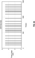
- Historical one-minute power consumption data of EWH 115 from a single household may be obtained as shown in FIG. 3A for example.
- Controller 125 may use a historian function to store this data in a database and then retrieve it as needed.
- EWH 115 may either consume its rated power (e.g., 4.5 kW) or consume zero power.' From this data, the number of minutes EWH 115 is turned on in a certain period (e.g., 15 min.) may be derived, which in turn provides consumed power: P EWH _ his n .
- the historical power usage P EWH _ his [ n ] as determined above may be fed into a stochastic prediction model that may forecast an expected kW consumption: P EWH _ est n .
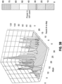
- FIG. 3B shows power in kW used by EWH 115 in all hours of the day in all days of a month from a certain household (e.g., home 105).
- FIG. 3B shows concentration of power consumption in a few hours in the morning for example.
- a Pearson correlation coefficient may be computed between the power usage in the current period n and that of the previous period n 1 for a certain length of days (e.g.,14 days).
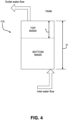
- the temperature distribution in EWH 115's water tank may follow a pattern as shown FIG. 4 .
- the energy balance in the water tank may be captured approximately as a two-mass model shown in FIG. 4 .
- the top mass may have an average temperature of T u while the bottom mass may have an average temperature of T l .
- Water may be injected into the tank through the inlet at a bottom while hot water leaves from the top at a mass flow rate of ⁇ .
- Ambient temperature may be provided by T amb .
- UA WH may be the heat loss coefficient of the tank
- Q elec may be the electrical energy input
- C p may be the specific heat of water
- C w may be the thermal capacitance of water.
- Now, if initial steady level of hot water: h ss ⁇ H This leads to the following relation: Q elec + UA WH T amb
- T upper , T lower , T amb may be respectively considered as 125 °F, 50°F, 70°F in approximate terms.
- Provided measurement of energy is known in a certain period.
- the new reserve capacity of hot water in real time may be estimated in the following relations:
- method 200 may advance to stage 220 where smart meter 120 may determine a safe deferred time for EWH 115 based on the determined reserve capacity. For example, once the reserve capacity is estimated, the safe deferral time for turning on EWH 115 at the beginning of grid service event 130 may be computed.
- safe deferred time 0 mins. This may guarantee a minimum reserve capacity of ⁇ safe at the end of each grid service event, preventing customer discomfort or cold showers.
- ⁇ safe is typically assigned as 10%-25% of hot water tank capacity, depending on the need of the homeowners.
- method 200 may continue to stage 230 where smart meter 120 may receive grid service event 130 initiation.
- grid service event 130 may comprise a demand response from utility 110 seeking to adjust the demand for power (e.g., causing EWH 115 to not heat water) instead of adjusting the supply.
- method 200 may proceed to stage 240 where smart meter 120 may cause, in response to receiving grid service event 130 initiation, EWH 115 to not heat water for the determined safe deferred time.
- controller 125 under the command of smart meter 120 may shut off the power to EWH 115 for the duration of the safe deferred time.
- controller 125 under the command of smart meter 120 may turn on the power to EWH 115.
- FIG. 5 is a block diagram of a use case for control of an electric water heater based on a two-mass model.
- the process shown in FIG. 5 is an example used case and other use cases may be realized consistent with embodiments of the disclosure.
- smart meter may determine a safe deferred time for blocking the turning on of EWH 115.
- historical power consumption may be obtained (stage 505) as described above and an estimated power usage may be determined (stage 510) as described above. Then it is determined if the power usage is greater than 10% rated (stage 515).
- ⁇ may be set to 0.9 or 90% of the capacity of the EWH tank (stage 520). If the power usage is greater than 10% rated, ⁇ may be estimated from hot water flow (stage 525). In this way, ⁇ may be monitored (stage 530) on an ongoing basis. Then, when grid service event 130 is received (stage 535) the monitored estimated ⁇ may be evaluated (stage 540). If the estimated ⁇ is less than ⁇ safe , EWH 115 may not be controlled in response to the received grid service event 130 (stage 545).
- FIG. 6 shows computing device 600.
- computing device 600 may include a processing unit 610 and a memory unit 615.
- Memory unit 615 may include a software module 620 and a database 625.
- software module 620 may perform, for example, processes for providing control of an EWH based on a two-mass model as described above with respect to FIG. 2 .
- Computing device 600 may provide an operating environment for smart meter 120 and/or controller 125. Smart meter 120 and controller 125 may operate in other environments and are not limited to computing device 600.
- Computing device 600 may be implemented using a smart meter, a Wi-Fi access point, a tablet device, a mobile device, a smart phone, a telephone, a remote control device, a set-top box, a digital video recorder, a cable modem, a personal computer, a network computer, a mainframe, a router, a switch, a server cluster, a smart TV-like device, a network storage device, a network relay device, or other similar microcomputer-based device.
- Computing device 600 may comprise any computer operating environment, such as hand-held devices, multiprocessor systems, microprocessor-based or programmable sender electronic devices, minicomputers, mainframe computers, and the like.
- Computing device 600 may also be practiced in distributed computing environments where tasks are performed by remote processing devices.
- the aforementioned systems and devices are examples, and computing device 600 may comprise other systems or devices.
- Embodiments of the disclosure may be implemented as a computer process (method), a computing system, or as an article of manufacture, such as a computer program product or computer readable media.
- the computer program product may be a computer storage media readable by a computer system and encoding a computer program of instructions for executing a computer process.
- the computer program product may also be a propagated signal on a carrier readable by a computing system and encoding a computer program of instructions for executing a computer process.
- the present disclosure may be embodied in hardware and/or in software (including firmware, resident software, micro-code, etc.).
- embodiments of the present disclosure may take the form of a computer program product on a computer-usable or computer-readable storage medium having computer-usable or computer-readable program code embodied in the medium for use by or in connection with an instruction execution system.
- a computer-usable or computer-readable medium may be any medium that can contain, store, communicate, propagate, or transport the program for use by or in connection with the instruction execution system, apparatus, or device.
- the computer-usable or computer-readable medium may be, for example but not limited to, an electronic, magnetic, optical, electromagnetic, infrared, or semiconductor system, apparatus, device, or propagation medium. More specific computer-readable medium examples (a non-exhaustive list), the computer-readable medium may include the following: an electrical connection having one or more wires, a portable computer diskette, a random access memory (RAM), a read-only memory (ROM), an erasable programmable read-only memory (EPROM or Flash memory), an optical fiber, and a portable compact disc read-only memory (CD-ROM).
- RAM random access memory
- ROM read-only memory
- EPROM or Flash memory erasable programmable read-only memory
- CD-ROM portable compact disc read-only memory
- the computer-usable or computer-readable medium could even be paper or another suitable medium upon which the program is printed, as the program can be electronically captured, via, for instance, optical scanning of the paper or other medium, then compiled, interpreted, or otherwise processed in a suitable manner, if necessary, and then stored in a computer memory.
- embodiments of the disclosure may be practiced in an electrical circuit comprising discrete electronic elements, packaged or integrated electronic chips containing logic gates, a circuit utilizing a microprocessor, or on a single chip containing electronic elements or microprocessors.
- Embodiments of the disclosure may also be practiced using other technologies capable of performing logical operations such as, for example, AND, OR, and NOT, including but not limited to, mechanical, optical, fluidic, and quantum technologies.
- embodiments of the disclosure may be practiced within a general purpose computer or in any other circuits or systems.
- Embodiments of the disclosure may be practiced via a system-on-a-chip (SOC) where each or many of the element illustrated in FIG. 1 may be integrated onto a single integrated circuit.
- SOC system-on-a-chip
- Such an SOC device may include one or more processing units, graphics units, communications units, system virtualization units and various application functionality all of which may be integrated (or "burned") onto the chip substrate as a single integrated circuit.
- the functionality described herein with respect to embodiments of the disclosure may be performed via application-specific logic integrated with other components of computing device 600 on the single integrated circuit (chip).
- Embodiments of the present disclosure are described above with reference to block diagrams and/or operational illustrations of methods, systems, and computer program products according to embodiments of the disclosure.
- the functions/acts noted in the blocks may occur out of the order as shown in any flowchart.
- two blocks shown in succession may in fact be executed substantially concurrently or the blocks may sometimes be executed in the reverse order, depending upon the functionality/acts involved.
- a method comprising: determining a reserve capacity of an Electric Water Heater (EWH); determining a safe deferred time for the EWH based on the determined reserve capacity; receiving a grid service event initiation; and causing, in response to receiving the grid service event initiation, the EWH to not heat water for the determined safe deferred time.
- EWH Electric Water Heater
- Aspect 2 The method of aspect 1, wherein determining the reserve capacity of the EWH comprises determining the reserve capacity of the EWH based on estimated power usage of the EWH.
- Aspect 3 The method of aspect 2, wherein determining the reserve capacity of the EWH based on estimated power usage of the EWH comprises: obtaining historic power usage of the EWH; and feeding the obtained historic power usage of the EWH into a stochastic prediction model.
- Aspect 4 The method of aspect 1, wherein determining the reserve capacity of the EWH comprises determining the reserve capacity of the EWH based on a two-mass model of the EWH.
- Aspect 5 The method of aspect 4, wherein a first mass of the two-mass model is associated with water in an upper portion of the EWH and a second mass of the two-mass model is associated with water in a lower portion of the EWH.
- Aspect 6 The method of aspect 1, wherein causing the EWH to not heat water for the determined safe deferred time comprises causing the EWH to not heat water for the determined safe deferred time when a hot water capacity estimated to be left at an end of the safe deferred time is greater than a predetermined threshold.
- Aspect 7 The method of aspect 6, wherein the predetermined threshold is between 10% and 25% as defined by a user.
- Aspect 8 The method of aspect 1, wherein the method is performed by a computing device at a home where the EWH is disposed.
- Aspect 9 The method of aspect 8, wherein the computing device is a smart meter.
- a system comprising: a memory storage; and a processing unit coupled to the memory storage, wherein the processing unit is operative to: determine a reserve capacity of an Electric Water Heater (EWH); determine a safe deferred time for the EWH based on the determined reserve capacity; receive a grid service event initiation; and cause, in response to receiving the grid service event initiation, the EWH to not heat water for the determined safe deferred time.
- EWH Electric Water Heater
- Aspect 11 The system of aspect 10, wherein the processing unit being operative to determine the reserve capacity of the EWH comprises the processing unit being operative to determine the reserve capacity of the EWH based on estimated power usage of the EWH.
- Aspect 12 The system of aspect 11, wherein the processing unit being operative to determine the reserve capacity of the EWH based on estimated power usage of the EWH comprises: obtain historic power usage of the EWH; and feed the obtained historic power usage of the EWH into a stochastic prediction model.
- Aspect 13 The system of aspect 10, wherein the processing unit being operative to determine the reserve capacity of the EWH comprises the processing unit being operative to determine the reserve capacity of the EWH based on a two-mass model of the EWH.
- Aspect 14 The system of aspect 13, wherein a first mass of the two-mass model is associated with water in an upper portion of the EWH and a second mass of the two-mass model is associated with water in a lower portion of the EWH.
- Aspect 15 The system of aspect 10, wherein the processing unit being operative to cause the EWH to not heat water for the determined safe deferred time comprises the processing unit being operative to cause the EWH to not heat water for the determined safe deferred time when a hot water capacity estimated to be left at an end of the safe deferred time is greater than a predetermined threshold.
- a computer-readable medium that stores a set of instructions which when executed perform a method executed by the set of instructions comprising: determining a reserve capacity of an Electric Water Heater (EWH); determining a safe deferred time for the EWH based on the determined reserve capacity; receiving a grid service event initiation; and causing, in response to receiving the grid service event initiation, the EWH to not heat water for the determined safe deferred time.
- EWH Electric Water Heater
- determining the reserve capacity of the EWH comprises determining the reserve capacity of the EWH based on estimated power usage of the EWH.
- Aspect 18 The computer-readable medium of aspect 17, wherein determining the reserve capacity of the EWH based on estimated power usage of the EWH comprises: obtaining historic power usage of the EWH; and feeding the obtained historic power usage of the EWH into a stochastic prediction model.
- Aspect 19 The computer-readable medium of aspect 16, wherein determining the reserve capacity of the EWH comprises determining the reserve capacity of the EWH based on a two-mass model of the EWH.
- Aspect 20 The computer-readable medium of aspect 19, wherein a first mass of the two-mass model is associated with water in an upper portion of the EWH and a second mass of the two-mass model is associated with water in a lower portion of the EWH.
Landscapes
- Engineering & Computer Science (AREA)
- Physics & Mathematics (AREA)
- Thermal Sciences (AREA)
- Chemical & Material Sciences (AREA)
- Combustion & Propulsion (AREA)
- Mechanical Engineering (AREA)
- General Engineering & Computer Science (AREA)
- Computer Hardware Design (AREA)
- Power Engineering (AREA)
- Heat-Pump Type And Storage Water Heaters (AREA)
- Management, Administration, Business Operations System, And Electronic Commerce (AREA)
Abstract
Control of an electric water heater based on a two-mass model may be provided. First, a reserve capacity of an Electric Water Heater (EWH) may be determined. Next, a safe deferred time for the EWH based on the determined reserve capacity may be determined. Then a grid service event initiation may be received. In response to receiving the grid service event initiation, the EWH may be caused to not heat water for the determined safe deferred time.
Description
- The present disclosure relates generally to control of an electric water heater.
- Demand response is a change in the power consumption of an electric utility customer to better match the demand for power with the supply. Until recently, electric energy could not be easily stored, so utilities have traditionally matched demand and supply by throttling the production rate of their power plants, taking generating units on or off line, or importing power from other utilities. There are limits to what can be achieved on the supply side, because some generating units can take a long time to come up to full power, some units may be very expensive to operate, and demand can at times be greater than the capacity of all the available power plants put together. Demand response seeks to adjust the demand for power instead of adjusting the supply.
- Utilities may signal demand requests to their customers in a variety of ways, including simple off-peak metering, in which power is cheaper at certain times of the day, and smart metering, in which explicit requests or changes in price can be communicated to customers. The customer may adjust power demand by postponing some tasks that require large amounts of electric power, or may decide to pay a higher price for their electricity. Some customers may switch part of their consumption to alternate sources, such as on-site solar panels and batteries.
- The accompanying drawings, which are incorporated in and constitute a part of this disclosure, illustrate various embodiments of the present disclosure. In the drawings:
-
FIG. 1 is a block diagram of an operating environment for providing control of an Electric Water Heater (EWH) based on a two-mass model; -
FIG. 2 is a flow chart of a method for providing control of an EWH based on a two-mass model; -
FIG. 3A illustrates power consumption of an EWH; -
FIG. 3B illustrates hourly variation of power of an EWH; -
FIG. 4 illustrates a two-mass model of an EWH; -
FIG. 5 is a block diagram of a use case for control of an EWH based on a two-mass model; and -
FIG. 6 is a block diagram of a computing device. - Control of an electric water heater based on a two-mass model may be provided. First, a reserve capacity of an Electric Water Heater (EWH) may be determined. Next, a safe deferred time for the EWH based on the determined reserve capacity may be determined. Then a grid service event initiation may be received. In response to receiving the grid service event initiation, the EWH may be caused to not heat water for the determined safe deferred time.
- Both the foregoing overview and the following example embodiments are examples and explanatory only and should not be considered to restrict the disclosure's scope, as described, and claimed. Furthermore, features and/or variations may be provided in addition to those described. For example, embodiments of the disclosure may be directed to various feature combinations and sub-combinations described in the example embodiments.
- The following detailed description refers to the accompanying drawings. Wherever possible, the same reference numbers are used in the drawings and the following description to refer to the same or similar elements. While embodiments of the disclosure may be described, modifications, adaptations, and other implementations are possible. For example, substitutions, additions, or modifications may be made to the elements illustrated in the drawings, and the methods described herein may be modified by substituting, reordering, or adding stages to the disclosed methods. Accordingly, the following detailed description does not limit the disclosure. Instead, the proper scope of the disclosure is defined by the appended claims.
- Embodiments of the disclosure may provide control of an Electric Water Heater (EWH) of an individual household such that the consumed power may be controlled from an edge or household level in response to a grid service event. Through intelligently delaying the turning on of the EWH, a certain reserve capacity of power may be obtained during the grid service event. This reserve capacity may add to the aggregate reserve of controllable loads in a household allowing the edge controller to take part in responding to the grid service event as requested by a central utility level control.
-
FIG. 1 shows anoperating environment 100 for providing control of an electric water heater based on a two-mass model. As shown inFIG. 1 ,operating environment 100 may comprise of ahome 105 and autility 110.Home 105 may include an Electric Water Heater (EWH) 115 and asmart meter 120.Smart meter 120 may operatecontroller 125 associated with EWH 115 and may receive a gridservice event request 130 from autility 110 as described in greater detail below. -
Smart meter 120 may comprise an electronic device that records information such as consumption of electric energy, voltage levels, current, power, and power factor.Smart meter 120 may communicate the information to the consumer (e.g., owner of home 105) for greater clarity of consumption behavior, and electricity suppliers (e.g., utility 110) for system monitoring and customer billing.Smart meter 120 may record energy near real-time, and report regularly, short intervals throughout the day. - In addition,
smart meter 120 may enable two-way communication betweensmart meter 120 and a central system (e.g., utility 110). Communications betweensmart meter 120 andutility 110 may be wireless via mobile networks or via fixed wired connections such as Power Line Carrier (PLC).Smart meter 120, for example, may receive a gridservice event request 130 fromutility 110 as described in greater detail below. Gridservice event request 130 may comprise a demand response fromutility 110 seeking to adjust the demand for power (e.g., causing EWH 115 to not heat water) instead of adjusting the supply. -
Controller 125 may monitor the power consumption of EWH 115 and report the monitored power consumption tosmart meter 120. Also,controller 125, under the command ofsmart meter 120, may shut off the power to EWH 115 and may turn on the power to EWH 115. Shutting off the power to EWH 115 may cause EWH 115 to not heat water. - EWH 115 may be considered a potent source of energy reserve in a household as it may be designed to store a certain volume of hot water for ready usage. This reserve may be exploited by edge control (e.g.,
smart meter 120 and controller 125) to respond to gridservice event request 130. In EWH 115, cold water may be circulated from the bottom of the tank while hot water outlet may be at the top. EWH 115 may comprise two heating elements, one located near the top and the other near the bottom. The control of each heating element may be managed by their respective thermostats in a way that the elements may heat up the water when temperature falls below a preset threshold. The lower heating element may heat up the inlet cold-water to an intermediate hot temperature, while the top one may maintain the hot water temperature at the top outlet. The top heating element may have the priority over the bottom one. The resultant behavior may be an on/off control maintaining the temperature at both the top and bottom half of the chamber within certain bounds. - The elements described above of operating environment 100 (e.g.,
smart meter 120 and controller 125) may be practiced in hardware and/or in software (including firmware, resident software, micro-code, etc.) or in any other circuits or systems. The elements of operating environment 100 (e.g.,smart meter 120 and controller 125) may be practiced in electrical circuits comprising discrete electronic elements, packaged or integrated electronic chips containing logic gates, a circuit utilizing a microprocessor, or on a single chip containing electronic elements or microprocessors. Furthermore, the elements of operating environment 100 (e.g.,smart meter 120 and controller 125) may also be practiced using other technologies capable of performing logical operations such as, for example, AND, OR, and NOT, including but not limited to, mechanical, optical, fluidic, and quantum technologies. As described in greater detail below with respect toFIG. 6 , the elements of operating environment 100 (e.g.,smart meter 120 and controller 125) may be practiced in acomputing device 600. - When controlling
EWH 115, the following issues may be considered: i) the turning on ofEWH 115 may be uncertain and may be triggered by random human behavior; ii) during hours of substantial hot water usage (e.g., when a dishwasher is running), responding togrid service event 130 may lead to customer discomfort like cold showers; iii)EWH 115, compliant with Consumer Technology Association (CTA) 2045 standard, may provide reserve capacity as a measurement, in others, no measurements may be available, installation of additional sensors to obtain temperature or low measurements may lead to tampering the manufacturer's warranty forEWH 115; and iv) controllability may only be available in the form of blocking of the heating elements. In order to tackle these issues, embodiments of the disclosure may take the following into consideration: i)EWH 115 may comprise a two-mass system, upper and lower chamber with a high and low temperature; ii) temperature of the hot water at the outlet, ground water at the inlet, ambient temperature, power rating, and tank capacity may be known or may be estimated; and iii) parameters like specific heat and density of water may be known. -
FIG. 2 is a flow chart setting forth the general stages involved in amethod 200 consistent with an embodiment of the disclosure for providing control of an electric water heater based on a two-mass model.Method 200 may be implemented usingsmart meter 120 as described in more detail above with respect toFIG. 1 . However, embodiments of the disclosure may be implemented by any computing device, for example,controller 125 or acomputing device 600 as described in greater detail inFIG. 6 below. Furthermore,method 200 may be performed anywhere, for example, athome 105, atutility 110, on in the cloud. Ways to implement the stages ofmethod 200 will be described in greater detail below. -
Method 200 may begin at startingblock 205 and proceed to stage 210 wheresmart meter 120 may determine a reserve capacity ofEWH 115. For example, historic power usage ofEWH 115 may be obtained bycontroller 125 and provided tosmart meter 120. - Historical one-minute power consumption data of
EWH 115 from a single household may be obtained as shown inFIG. 3A for example.Controller 125 may use a historian function to store this data in a database and then retrieve it as needed.EWH 115 may either consume its rated power (e.g., 4.5 kW) or consume zero power.' From this data, the number ofminutes EWH 115 is turned on in a certain period (e.g., 15 min.) may be derived, which in turn provides consumed power:
- The historical power usage P EWH_his [n] as determined above may be fed into a stochastic prediction model that may forecast an expected kW consumption:

- There is a correlation between daily power usage of
EWH 115 with that of the hour of operation. The plot inFIG. 3B may show power in kW used byEWH 115 in all hours of the day in all days of a month from a certain household (e.g., home 105).FIG. 3B shows concentration of power consumption in a few hours in the morning for example. Based on this understanding, a Pearson correlation coefficient may be computed between the power usage in the current period n and that of the previous period n1 for a certain length of days (e.g.,14 days).
- Based on the calculated correlation coefficient and the measured power in the previous period n1, the power that will be consumed in the next period n can be predicted following the relation as shown below:

- In a certain interval, if the estimated power usage PEWH_est [n] is known, that information may be used to delay the turning on of
EWH 115 by a certain/fixed duration of time. This may facilitatecontroller 125 to minimize the aggregate power demand in the household during grid service events. But for that, a reserve capacity of hot water may need to be estimated in real time so that customer comfort bounds are not violated. The problem may thus be transformed to a determination of reserve capacity of hot water in the tank ofEWH 115 with obtained power measurements. - The temperature distribution in
EWH 115's water tank may follow a pattern as shownFIG. 4 . As observed, there may be a sharp change in water temperature along the length of the water tank. Consequently, the energy balance in the water tank may be captured approximately as a two-mass model shown inFIG. 4 . In the approximate two-mass model, the top mass may have an average temperature of Tu while the bottom mass may have an average temperature of Tl . Water may be injected into the tank through the inlet at a bottom while hot water leaves from the top at a mass flow rate of ṁ. Ambient temperature may be provided by Tamb. UAWH may be the heat loss coefficient of the tank, Qelec may be the electrical energy input, Cp may be the specific heat of water, and Cw may be the thermal capacitance of water. The dynamics of the height of the top hot water mass (h) may be defined by the following differential equation:


- The above relation may be valid in case when water is used, and water is not used in steady state. Considering the scenario when hot water is not used, ṁCp = 0:


- Tupper, Tlower, Tamb may be respectively considered as 125 °F, 50°F, 70°F in approximate terms. Provided measurement of energy is known in a certain period. The new reserve capacity of hot water in real time may be estimated in the following relations:
- i) If energy usage > a preset threshold (10% of rated energy in a period)

- ii) If energy usage <a preset threshold (10% of rated energy in a period)

- From
stage 210, wheresmart meter 120 determines the reserve capacity ofEWH 115,method 200 may advance to stage 220 wheresmart meter 120 may determine a safe deferred time forEWH 115 based on the determined reserve capacity. For example, once the reserve capacity is estimated, the safe deferral time for turning onEWH 115 at the beginning ofgrid service event 130 may be computed. If a full tank (e.g., 50 gallons) of hot water needs to be heated, the energy required may be computed as below:

EWH 115 with 4.5 kW rated power, if there is a full tank of hot water, the number of minutes the turning on ofEWH 115 may be deferred by:

- Also, in some embodiments, if α < αsafe,
EWH 115 may not participate ingrid service event 130, safe deferred time = 0 mins. This may guarantee a minimum reserve capacity of αsafe at the end of each grid service event, preventing customer discomfort or cold showers. αsafe is typically assigned as 10%-25% of hot water tank capacity, depending on the need of the homeowners. - Once
smart meter 120 determines the safe deferred time forEWH 115 based on the determined reserve capacity instage 220,method 200 may continue to stage 230 wheresmart meter 120 may receivegrid service event 130 initiation. For example,grid service event 130 may comprise a demand response fromutility 110 seeking to adjust the demand for power (e.g., causingEWH 115 to not heat water) instead of adjusting the supply. - After
smart meter 120 receives gridservice event initiation 130 instage 230,method 200 may proceed to stage 240 wheresmart meter 120 may cause, in response to receivinggrid service event 130 initiation,EWH 115 to not heat water for the determined safe deferred time. For example,controller 125 under the command ofsmart meter 120, may shut off the power toEWH 115 for the duration of the safe deferred time. At the end of the safe deferred time,controller 125 under the command ofsmart meter 120, may turn on the power toEWH 115. Oncesmart meter 120 causes, in response to receiving gridservice event initiation 130,EWH 115 to not heat water for the determined safe deferred time instage 240,method 200 may then end atstage 250. -
FIG. 5 is a block diagram of a use case for control of an electric water heater based on a two-mass model. The process shown inFIG. 5 is an example used case and other use cases may be realized consistent with embodiments of the disclosure. Consistent with embodiments of the disclosure, based on the reserve capacity estimated at the beginning ofgrid service event 130, smart meter may determine a safe deferred time for blocking the turning on ofEWH 115. As shown inFIG. 5 , historical power consumption may be obtained (stage 505) as described above and an estimated power usage may be determined (stage 510) as described above. Then it is determined if the power usage is greater than 10% rated (stage 515). If the power usage is not greater than 10% rated, α may be set to 0.9 or 90% of the capacity of the EWH tank (stage 520). If the power usage is greater than 10% rated, α may be estimated from hot water flow (stage 525). In this way, α may be monitored (stage 530) on an ongoing basis. Then, whengrid service event 130 is received (stage 535) the monitored estimated α may be evaluated (stage 540). If the estimated α is less than αsafe,EWH 115 may not be controlled in response to the received grid service event 130 (stage 545). However, if the estimated α is greater than or equal to αsafe, the safe deferred time is obtained and theEWH 115 may be blocked from running for safe deferred time == 122 ∗ (α - αsafe) mins (stage 550). -
FIG. 6 showscomputing device 600. As shown inFIG. 6 ,computing device 600 may include aprocessing unit 610 and amemory unit 615.Memory unit 615 may include asoftware module 620 and adatabase 625. While executing onprocessing unit 610,software module 620 may perform, for example, processes for providing control of an EWH based on a two-mass model as described above with respect toFIG. 2 .Computing device 600, for example, may provide an operating environment forsmart meter 120 and/orcontroller 125.Smart meter 120 andcontroller 125 may operate in other environments and are not limited tocomputing device 600. -
Computing device 600 may be implemented using a smart meter, a Wi-Fi access point, a tablet device, a mobile device, a smart phone, a telephone, a remote control device, a set-top box, a digital video recorder, a cable modem, a personal computer, a network computer, a mainframe, a router, a switch, a server cluster, a smart TV-like device, a network storage device, a network relay device, or other similar microcomputer-based device.Computing device 600 may comprise any computer operating environment, such as hand-held devices, multiprocessor systems, microprocessor-based or programmable sender electronic devices, minicomputers, mainframe computers, and the like.Computing device 600 may also be practiced in distributed computing environments where tasks are performed by remote processing devices. The aforementioned systems and devices are examples, andcomputing device 600 may comprise other systems or devices. - Embodiments of the disclosure, for example, may be implemented as a computer process (method), a computing system, or as an article of manufacture, such as a computer program product or computer readable media. The computer program product may be a computer storage media readable by a computer system and encoding a computer program of instructions for executing a computer process. The computer program product may also be a propagated signal on a carrier readable by a computing system and encoding a computer program of instructions for executing a computer process. Accordingly, the present disclosure may be embodied in hardware and/or in software (including firmware, resident software, micro-code, etc.). In other words, embodiments of the present disclosure may take the form of a computer program product on a computer-usable or computer-readable storage medium having computer-usable or computer-readable program code embodied in the medium for use by or in connection with an instruction execution system. A computer-usable or computer-readable medium may be any medium that can contain, store, communicate, propagate, or transport the program for use by or in connection with the instruction execution system, apparatus, or device.
- The computer-usable or computer-readable medium may be, for example but not limited to, an electronic, magnetic, optical, electromagnetic, infrared, or semiconductor system, apparatus, device, or propagation medium. More specific computer-readable medium examples (a non-exhaustive list), the computer-readable medium may include the following: an electrical connection having one or more wires, a portable computer diskette, a random access memory (RAM), a read-only memory (ROM), an erasable programmable read-only memory (EPROM or Flash memory), an optical fiber, and a portable compact disc read-only memory (CD-ROM). Note that the computer-usable or computer-readable medium could even be paper or another suitable medium upon which the program is printed, as the program can be electronically captured, via, for instance, optical scanning of the paper or other medium, then compiled, interpreted, or otherwise processed in a suitable manner, if necessary, and then stored in a computer memory.
- While certain embodiments of the disclosure have been described, other embodiments may exist. Furthermore, although embodiments of the present disclosure have been described as being associated with data stored in memory and other storage mediums, data can also be stored on, or read from other types of computer-readable media, such as secondary storage devices, like hard disks, floppy disks, or a CD-ROM, a carrier wave from the Internet, or other forms of RAM or ROM. Further, the disclosed methods' stages may be modified in any manner, including by reordering stages and/or inserting or deleting stages, without departing from the disclosure.
- Furthermore, embodiments of the disclosure may be practiced in an electrical circuit comprising discrete electronic elements, packaged or integrated electronic chips containing logic gates, a circuit utilizing a microprocessor, or on a single chip containing electronic elements or microprocessors. Embodiments of the disclosure may also be practiced using other technologies capable of performing logical operations such as, for example, AND, OR, and NOT, including but not limited to, mechanical, optical, fluidic, and quantum technologies. In addition, embodiments of the disclosure may be practiced within a general purpose computer or in any other circuits or systems.
- Embodiments of the disclosure may be practiced via a system-on-a-chip (SOC) where each or many of the element illustrated in
FIG. 1 may be integrated onto a single integrated circuit. Such an SOC device may include one or more processing units, graphics units, communications units, system virtualization units and various application functionality all of which may be integrated (or "burned") onto the chip substrate as a single integrated circuit. When operating via an SOC, the functionality described herein with respect to embodiments of the disclosure, may be performed via application-specific logic integrated with other components ofcomputing device 600 on the single integrated circuit (chip). - Embodiments of the present disclosure, for example, are described above with reference to block diagrams and/or operational illustrations of methods, systems, and computer program products according to embodiments of the disclosure. The functions/acts noted in the blocks may occur out of the order as shown in any flowchart. For example, two blocks shown in succession may in fact be executed substantially concurrently or the blocks may sometimes be executed in the reverse order, depending upon the functionality/acts involved.
- While the specification includes examples, the disclosure's scope is indicated by the following claims. Furthermore, while the specification has been described in language specific to structural features and/or methodological acts, the claims are not limited to the features or acts described above. Rather, the specific features and acts described above are disclosed as example for embodiments of the disclosure.
- Examples of the disclosure may be described according to the following aspects.
- Aspect 1. A method comprising: determining a reserve capacity of an Electric Water Heater (EWH); determining a safe deferred time for the EWH based on the determined reserve capacity; receiving a grid service event initiation; and causing, in response to receiving the grid service event initiation, the EWH to not heat water for the determined safe deferred time.
-
Aspect 2. The method of aspect 1, wherein determining the reserve capacity of the EWH comprises determining the reserve capacity of the EWH based on estimated power usage of the EWH. - Aspect 3. The method of
aspect 2, wherein determining the reserve capacity of the EWH based on estimated power usage of the EWH comprises: obtaining historic power usage of the EWH; and feeding the obtained historic power usage of the EWH into a stochastic prediction model. -
Aspect 4. The method of aspect 1, wherein determining the reserve capacity of the EWH comprises determining the reserve capacity of the EWH based on a two-mass model of the EWH. -
Aspect 5. The method ofaspect 4, wherein a first mass of the two-mass model is associated with water in an upper portion of the EWH and a second mass of the two-mass model is associated with water in a lower portion of the EWH. -
Aspect 6. The method of aspect 1, wherein causing the EWH to not heat water for the determined safe deferred time comprises causing the EWH to not heat water for the determined safe deferred time when a hot water capacity estimated to be left at an end of the safe deferred time is greater than a predetermined threshold. - Aspect 7. The method of
aspect 6, wherein the predetermined threshold is between 10% and 25% as defined by a user. - Aspect 8. The method of aspect 1, wherein the method is performed by a computing device at a home where the EWH is disposed.
- Aspect 9. The method of aspect 8, wherein the computing device is a smart meter.
-
Aspect 10. A system comprising: a memory storage; and a processing unit coupled to the memory storage, wherein the processing unit is operative to: determine a reserve capacity of an Electric Water Heater (EWH); determine a safe deferred time for the EWH based on the determined reserve capacity; receive a grid service event initiation; and cause, in response to receiving the grid service event initiation, the EWH to not heat water for the determined safe deferred time. - Aspect 11. The system of
aspect 10, wherein the processing unit being operative to determine the reserve capacity of the EWH comprises the processing unit being operative to determine the reserve capacity of the EWH based on estimated power usage of the EWH. - Aspect 12. The system of aspect 11, wherein the processing unit being operative to determine the reserve capacity of the EWH based on estimated power usage of the EWH comprises: obtain historic power usage of the EWH; and feed the obtained historic power usage of the EWH into a stochastic prediction model.
- Aspect 13. The system of
aspect 10, wherein the processing unit being operative to determine the reserve capacity of the EWH comprises the processing unit being operative to determine the reserve capacity of the EWH based on a two-mass model of the EWH. - Aspect 14. The system of aspect 13, wherein a first mass of the two-mass model is associated with water in an upper portion of the EWH and a second mass of the two-mass model is associated with water in a lower portion of the EWH.
-
Aspect 15. The system ofaspect 10, wherein the processing unit being operative to cause the EWH to not heat water for the determined safe deferred time comprises the processing unit being operative to cause the EWH to not heat water for the determined safe deferred time when a hot water capacity estimated to be left at an end of the safe deferred time is greater than a predetermined threshold. - Aspect 16. A computer-readable medium that stores a set of instructions which when executed perform a method executed by the set of instructions comprising: determining a reserve capacity of an Electric Water Heater (EWH); determining a safe deferred time for the EWH based on the determined reserve capacity; receiving a grid service event initiation; and causing, in response to receiving the grid service event initiation, the EWH to not heat water for the determined safe deferred time.
- Aspect 17. The computer-readable medium of aspect 16, wherein determining the reserve capacity of the EWH comprises determining the reserve capacity of the EWH based on estimated power usage of the EWH.
- Aspect 18. The computer-readable medium of aspect 17, wherein determining the reserve capacity of the EWH based on estimated power usage of the EWH comprises: obtaining historic power usage of the EWH; and feeding the obtained historic power usage of the EWH into a stochastic prediction model.
- Aspect 19. The computer-readable medium of aspect 16, wherein determining the reserve capacity of the EWH comprises determining the reserve capacity of the EWH based on a two-mass model of the EWH.
-
Aspect 20. The computer-readable medium of aspect 19, wherein a first mass of the two-mass model is associated with water in an upper portion of the EWH and a second mass of the two-mass model is associated with water in a lower portion of the EWH.
Claims (15)
- A method comprising:determining a reserve capacity of an Electric Water Heater (EWH);determining a safe deferred time for the EWH based on the determined reserve capacity;receiving a grid service event initiation; andcausing, in response to receiving the grid service event initiation, the EWH to not heat water for the determined safe deferred time.
- The method of claim 1, wherein determining the reserve capacity of the EWH comprises determining the reserve capacity of the EWH based on estimated power usage of the EWH.
- The method of claim 2, wherein determining the reserve capacity of the EWH based on estimated power usage of the EWH comprises:obtaining historic power usage of the EWH; andfeeding the obtained historic power usage of the EWH into a stochastic prediction model.
- The method of claim 1, wherein determining the reserve capacity of the EWH comprises determining the reserve capacity of the EWH based on a two-mass model of the EWH.
- The method of claim 4, wherein a first mass of the two-mass model is associated with water in an upper portion of the EWH and a second mass of the two-mass model is associated with water in a lower portion of the EWH.
- The method of claim 1, wherein causing the EWH to not heat water for the determined safe deferred time comprises causing the EWH to not heat water for the determined safe deferred time when a hot water capacity estimated to be left at an end of the safe deferred time is greater than a predetermined threshold.
- The method of claim 6, wherein the predetermined threshold is between 10% and 25% as defined by a user.
- The method of claim 1, wherein the method is performed by a computing device at a home where the EWH is disposed.
- The method of claim 8, wherein the computing device is a smart meter.
- A system comprising:a memory storage; anda processing unit coupled to the memory storage, wherein the processing unit is operative to:determine a reserve capacity of an Electric Water Heater (EWH);determine a safe deferred time for the EWH based on the determined reserve capacity;receive a grid service event initiation; andcause, in response to receiving the grid service event initiation, the EWH to not heat water for the determined safe deferred time.
- The system of claim 10, wherein the processing unit being operative to determine the reserve capacity of the EWH comprises the processing unit being operative to determine the reserve capacity of the EWH based on estimated power usage of the EWH.
- The system of claim 11, wherein the processing unit being operative to determine the reserve capacity of the EWH based on estimated power usage of the EWH comprises the processing unit being operative to:obtain historic power usage of the EWH; andfeed the obtained historic power usage of the EWH into a stochastic prediction model.
- The system of claim 10, wherein the processing unit being operative to determine the reserve capacity of the EWH comprises the processing unit being operative to determine the reserve capacity of the EWH based on a two-mass model of the EWH.
- The system of claim 13, wherein a first mass of the two-mass model is associated with water in an upper portion of the EWH and a second mass of the two-mass model is associated with water in a lower portion of the EWH.
- The system of claim 10, wherein the processing unit being operative to cause the EWH to not heat water for the determined safe deferred time comprises the processing unit being operative to cause the EWH to not heat water for the determined safe deferred time when a hot water capacity estimated to be left at an end of the safe deferred time is greater than a predetermined threshold.
Applications Claiming Priority (1)
| Application Number | Priority Date | Filing Date | Title |
|---|---|---|---|
| US202263325958P | 2022-03-31 | 2022-03-31 |
Publications (1)
| Publication Number | Publication Date |
|---|---|
| EP4253861A1 true EP4253861A1 (en) | 2023-10-04 |
Family
ID=85800644
Family Applications (1)
| Application Number | Title | Priority Date | Filing Date |
|---|---|---|---|
| EP23165398.1A Pending EP4253861A1 (en) | 2022-03-31 | 2023-03-30 | Control of an electric water heater based on a two-mass model |
Country Status (3)
| Country | Link |
|---|---|
| US (1) | US20230314044A1 (en) |
| EP (1) | EP4253861A1 (en) |
| CA (1) | CA3194523A1 (en) |
Families Citing this family (1)
| Publication number | Priority date | Publication date | Assignee | Title |
|---|---|---|---|---|
| CN117404817B (en) * | 2023-12-12 | 2024-04-02 | 珠海格力电器股份有限公司 | Method and device for determining water heater volume in multi-connection system |
Citations (4)
| Publication number | Priority date | Publication date | Assignee | Title |
|---|---|---|---|---|
| US20130193221A1 (en) * | 2006-01-27 | 2013-08-01 | Emerson Electric Co. | Water heater control using external temperature sensor |
| US20190277537A1 (en) * | 2014-12-22 | 2019-09-12 | Battelle Memorial Institute | Estimation of temperature states for an electric water heater from inferred resistance measurement |
| GB2578300A (en) * | 2018-10-19 | 2020-05-06 | Swanbarton Ltd | Balancing electrical power consumption on an electricity distribution network |
| WO2021001060A1 (en) * | 2019-07-03 | 2021-01-07 | Eaton Intelligent Power Limited | Demand response of loads having thermal reserves |
-
2023
- 2023-03-29 CA CA3194523A patent/CA3194523A1/en active Pending
- 2023-03-30 EP EP23165398.1A patent/EP4253861A1/en active Pending
- 2023-03-30 US US18/193,077 patent/US20230314044A1/en active Pending
Patent Citations (4)
| Publication number | Priority date | Publication date | Assignee | Title |
|---|---|---|---|---|
| US20130193221A1 (en) * | 2006-01-27 | 2013-08-01 | Emerson Electric Co. | Water heater control using external temperature sensor |
| US20190277537A1 (en) * | 2014-12-22 | 2019-09-12 | Battelle Memorial Institute | Estimation of temperature states for an electric water heater from inferred resistance measurement |
| GB2578300A (en) * | 2018-10-19 | 2020-05-06 | Swanbarton Ltd | Balancing electrical power consumption on an electricity distribution network |
| WO2021001060A1 (en) * | 2019-07-03 | 2021-01-07 | Eaton Intelligent Power Limited | Demand response of loads having thermal reserves |
Also Published As
| Publication number | Publication date |
|---|---|
| CA3194523A1 (en) | 2023-09-30 |
| US20230314044A1 (en) | 2023-10-05 |
Similar Documents
| Publication | Publication Date | Title |
|---|---|---|
| Lefebvre et al. | Measuring the efficiency of voltage reduction at Hydro-Québec distribution | |
| EP1025474B1 (en) | Environmental condition control and energy-management system and method | |
| US8068938B2 (en) | Method and system for managing a load demand on an electrical grid | |
| US8768528B2 (en) | Electrical thermal storage with edge-of-network tailored energy delivery systems and methods | |
| US8867908B2 (en) | Self-programming water heater | |
| US10282687B2 (en) | Systems and methods for managing power generation resources | |
| US20100138363A1 (en) | Smart grid price response service for dynamically balancing energy supply and demand | |
| US20120130556A1 (en) | Virtual power plant system and method incorporating renewal energy, storage and scalable value-based optimization | |
| Shah et al. | Cost-optimal consumption-aware electric water heating via thermal storage under time-of-use pricing | |
| US20170310140A1 (en) | System and method for reducing time-averaged peak charges | |
| US20130262654A1 (en) | Resource management system with resource optimization mechanism and method of operation thereof | |
| Hao et al. | Frequency regulation from flexible loads: Potential, economics, and implementation | |
| EP2525463B1 (en) | Reducing demand/response effects implementing volt/var control | |
| AU2014252667A1 (en) | System and method for performing demand response optimizations | |
| EP2972643A2 (en) | Electric power system control with planning of energy demand and energy efficiency using ami-based data analysis | |
| JP5203855B2 (en) | Hot water storage type hot water supply apparatus, operation planning apparatus, and operation planning method | |
| Mukherjee et al. | Electric Water Heaters for Transactive Systems: Model Evaluations and Performance Quantification. | |
| US20230314044A1 (en) | Control of an electric water heater based on a two-mass model | |
| EP4163862A1 (en) | Planning system, planning method, and program | |
| US9166408B2 (en) | Demand response management system and method with VAR support | |
| JP5779417B2 (en) | Operation management apparatus, operation management method, and operation management program | |
| Mathieu et al. | Characterizing the response of commercial and industrial facilities to dynamic pricing signals from the utility | |
| O'Connell et al. | Modelling and Assessment of the Capabilities of a Supermarket Refrigeration System for the Provision of Regulating Power | |
| Arafat et al. | Uncertainty impact on Aggregator performance for Peak Shaving | |
| Qazi et al. | Power balance provision through co-ordinated control of modern storage heater load |
Legal Events
| Date | Code | Title | Description |
|---|---|---|---|
| PUAI | Public reference made under article 153(3) epc to a published international application that has entered the european phase |
Free format text: ORIGINAL CODE: 0009012 |
|
| STAA | Information on the status of an ep patent application or granted ep patent |
Free format text: STATUS: REQUEST FOR EXAMINATION WAS MADE |
|
| 17P | Request for examination filed |
Effective date: 20230330 |
|
| AK | Designated contracting states |
Kind code of ref document: A1 Designated state(s): AL AT BE BG CH CY CZ DE DK EE ES FI FR GB GR HR HU IE IS IT LI LT LU LV MC ME MK MT NL NO PL PT RO RS SE SI SK SM TR |