EP4253855A1 - Air conditioner - Google Patents
Air conditioner Download PDFInfo
- Publication number
- EP4253855A1 EP4253855A1 EP23162801.7A EP23162801A EP4253855A1 EP 4253855 A1 EP4253855 A1 EP 4253855A1 EP 23162801 A EP23162801 A EP 23162801A EP 4253855 A1 EP4253855 A1 EP 4253855A1
- Authority
- EP
- European Patent Office
- Prior art keywords
- air conditioning
- refrigerant sensor
- time
- reference time
- control unit
- Prior art date
- Legal status (The legal status is an assumption and is not a legal conclusion. Google has not performed a legal analysis and makes no representation as to the accuracy of the status listed.)
- Granted
Links
Images


Classifications
-
- F—MECHANICAL ENGINEERING; LIGHTING; HEATING; WEAPONS; BLASTING
- F24—HEATING; RANGES; VENTILATING
- F24F—AIR-CONDITIONING; AIR-HUMIDIFICATION; VENTILATION; USE OF AIR CURRENTS FOR SCREENING
- F24F5/00—Air-conditioning systems or apparatus not covered by F24F1/00 or F24F3/00, e.g. using solar heat or combined with household units such as an oven or water heater
- F24F5/0007—Air-conditioning systems or apparatus not covered by F24F1/00 or F24F3/00, e.g. using solar heat or combined with household units such as an oven or water heater cooling apparatus specially adapted for use in air-conditioning
- F24F5/001—Compression cycle type
-
- F—MECHANICAL ENGINEERING; LIGHTING; HEATING; WEAPONS; BLASTING
- F24—HEATING; RANGES; VENTILATING
- F24F—AIR-CONDITIONING; AIR-HUMIDIFICATION; VENTILATION; USE OF AIR CURRENTS FOR SCREENING
- F24F11/00—Control or safety arrangements
- F24F11/30—Control or safety arrangements for purposes related to the operation of the system, e.g. for safety or monitoring
- F24F11/49—Control or safety arrangements for purposes related to the operation of the system, e.g. for safety or monitoring ensuring correct operation, e.g. by trial operation or configuration checks
-
- F—MECHANICAL ENGINEERING; LIGHTING; HEATING; WEAPONS; BLASTING
- F24—HEATING; RANGES; VENTILATING
- F24F—AIR-CONDITIONING; AIR-HUMIDIFICATION; VENTILATION; USE OF AIR CURRENTS FOR SCREENING
- F24F11/00—Control or safety arrangements
- F24F11/30—Control or safety arrangements for purposes related to the operation of the system, e.g. for safety or monitoring
- F24F11/32—Responding to malfunctions or emergencies
-
- F—MECHANICAL ENGINEERING; LIGHTING; HEATING; WEAPONS; BLASTING
- F24—HEATING; RANGES; VENTILATING
- F24F—AIR-CONDITIONING; AIR-HUMIDIFICATION; VENTILATION; USE OF AIR CURRENTS FOR SCREENING
- F24F11/00—Control or safety arrangements
- F24F11/30—Control or safety arrangements for purposes related to the operation of the system, e.g. for safety or monitoring
- F24F11/32—Responding to malfunctions or emergencies
- F24F11/36—Responding to malfunctions or emergencies to leakage of heat-exchange fluid
-
- F—MECHANICAL ENGINEERING; LIGHTING; HEATING; WEAPONS; BLASTING
- F24—HEATING; RANGES; VENTILATING
- F24F—AIR-CONDITIONING; AIR-HUMIDIFICATION; VENTILATION; USE OF AIR CURRENTS FOR SCREENING
- F24F11/00—Control or safety arrangements
- F24F11/50—Control or safety arrangements characterised by user interfaces or communication
- F24F11/52—Indication arrangements, e.g. displays
-
- F—MECHANICAL ENGINEERING; LIGHTING; HEATING; WEAPONS; BLASTING
- F24—HEATING; RANGES; VENTILATING
- F24F—AIR-CONDITIONING; AIR-HUMIDIFICATION; VENTILATION; USE OF AIR CURRENTS FOR SCREENING
- F24F11/00—Control or safety arrangements
- F24F11/50—Control or safety arrangements characterised by user interfaces or communication
- F24F11/61—Control or safety arrangements characterised by user interfaces or communication using timers
-
- F—MECHANICAL ENGINEERING; LIGHTING; HEATING; WEAPONS; BLASTING
- F24—HEATING; RANGES; VENTILATING
- F24F—AIR-CONDITIONING; AIR-HUMIDIFICATION; VENTILATION; USE OF AIR CURRENTS FOR SCREENING
- F24F11/00—Control or safety arrangements
- F24F11/62—Control or safety arrangements characterised by the type of control or by internal processing, e.g. using fuzzy logic, adaptive control or estimation of values
- F24F11/63—Electronic processing
- F24F11/64—Electronic processing using pre-stored data
-
- F—MECHANICAL ENGINEERING; LIGHTING; HEATING; WEAPONS; BLASTING
- F24—HEATING; RANGES; VENTILATING
- F24F—AIR-CONDITIONING; AIR-HUMIDIFICATION; VENTILATION; USE OF AIR CURRENTS FOR SCREENING
- F24F11/00—Control or safety arrangements
- F24F11/70—Control systems characterised by their outputs; Constructional details thereof
- F24F11/80—Control systems characterised by their outputs; Constructional details thereof for controlling the temperature of the supplied air
- F24F11/83—Control systems characterised by their outputs; Constructional details thereof for controlling the temperature of the supplied air by controlling the supply of heat-exchange fluids to heat-exchangers
- F24F11/84—Control systems characterised by their outputs; Constructional details thereof for controlling the temperature of the supplied air by controlling the supply of heat-exchange fluids to heat-exchangers using valves
-
- F—MECHANICAL ENGINEERING; LIGHTING; HEATING; WEAPONS; BLASTING
- F24—HEATING; RANGES; VENTILATING
- F24F—AIR-CONDITIONING; AIR-HUMIDIFICATION; VENTILATION; USE OF AIR CURRENTS FOR SCREENING
- F24F11/00—Control or safety arrangements
- F24F11/70—Control systems characterised by their outputs; Constructional details thereof
- F24F11/80—Control systems characterised by their outputs; Constructional details thereof for controlling the temperature of the supplied air
- F24F11/86—Control systems characterised by their outputs; Constructional details thereof for controlling the temperature of the supplied air by controlling compressors within refrigeration or heat pump circuits
-
- F—MECHANICAL ENGINEERING; LIGHTING; HEATING; WEAPONS; BLASTING
- F24—HEATING; RANGES; VENTILATING
- F24F—AIR-CONDITIONING; AIR-HUMIDIFICATION; VENTILATION; USE OF AIR CURRENTS FOR SCREENING
- F24F11/00—Control or safety arrangements
- F24F11/89—Arrangement or mounting of control or safety devices
-
- F—MECHANICAL ENGINEERING; LIGHTING; HEATING; WEAPONS; BLASTING
- F25—REFRIGERATION OR COOLING; COMBINED HEATING AND REFRIGERATION SYSTEMS; HEAT PUMP SYSTEMS; MANUFACTURE OR STORAGE OF ICE; LIQUEFACTION SOLIDIFICATION OF GASES
- F25B—REFRIGERATION MACHINES, PLANTS OR SYSTEMS; COMBINED HEATING AND REFRIGERATION SYSTEMS; HEAT PUMP SYSTEMS
- F25B13/00—Compression machines, plants or systems, with reversible cycle
-
- F—MECHANICAL ENGINEERING; LIGHTING; HEATING; WEAPONS; BLASTING
- F25—REFRIGERATION OR COOLING; COMBINED HEATING AND REFRIGERATION SYSTEMS; HEAT PUMP SYSTEMS; MANUFACTURE OR STORAGE OF ICE; LIQUEFACTION SOLIDIFICATION OF GASES
- F25B—REFRIGERATION MACHINES, PLANTS OR SYSTEMS; COMBINED HEATING AND REFRIGERATION SYSTEMS; HEAT PUMP SYSTEMS
- F25B2500/00—Problems to be solved
- F25B2500/22—Preventing, detecting or repairing leaks of refrigeration fluids
- F25B2500/222—Detecting refrigerant leaks
-
- F—MECHANICAL ENGINEERING; LIGHTING; HEATING; WEAPONS; BLASTING
- F25—REFRIGERATION OR COOLING; COMBINED HEATING AND REFRIGERATION SYSTEMS; HEAT PUMP SYSTEMS; MANUFACTURE OR STORAGE OF ICE; LIQUEFACTION SOLIDIFICATION OF GASES
- F25B—REFRIGERATION MACHINES, PLANTS OR SYSTEMS; COMBINED HEATING AND REFRIGERATION SYSTEMS; HEAT PUMP SYSTEMS
- F25B49/00—Arrangement or mounting of control or safety devices
- F25B49/005—Arrangement or mounting of control or safety devices of safety devices
Definitions
- the present disclosure relates to air conditioners.
- Japanese Patent No. 6656490 discloses that an air conditioner that makes a pre-event notification before the cumulative energization time of a refrigerant sensor reaches the service life time of the refrigerant sensor, that makes a post-event notification when the cumulative energization time has reached the service life time of the refrigerant sensor, and that when the refrigerant sensor failed after the cumulative energization time had reached the service life of the refrigerant sensor, makes a notification on the service life of the refrigerant sensor and then stops the air conditioning operation.
- the present disclosure provides an air conditioner that allows the user to be more easily aware of the service life of the refrigerant sensor and thus has improved safety.
- An air conditioner is an air conditioner including an outdoor unit, an indoor unit that is connected to the outdoor unit via a refrigerant pipe and performs air conditioning in an air conditioning space, a refrigerant sensor that detects leakage, in the air conditioning space, of refrigerant, and a remote controller for operating air conditioning operation, the air conditioner including a control unit that, in a case in which the cumulative energization time of the refrigerant sensor has reached a reference time, performs control so as to make a warning notification on the remote controller and stop air conditioning operation.
- the cumulative energization time of the refrigerant sensor has reached the reference time, an alert notification is made on a remote controller, and also the air conditioning operation is stopped, and thus, the user is more easily aware of the alert notification on the remote controller because of the stoppage of the air conditioning operation.
- the user can take measures on the service life of the refrigerant sensor such as making contact with a maintenance provider, and this leads to improvement of the safety.
- the conventional technique includes a pre-event notification, a service-life-time notification, and a post-event notification regarding the service life of the refrigerant sensor, there is possibility that just notifying the service life of the refrigerant sensor cannot allow the user to be aware of the notification, and the inventors having realized this problem constructed the subject matter of the present disclosure to solve the problem.
- the present disclosure provides an air conditioner that allows the user to be more easily aware of the service life of the refrigerant sensor and thus has improved safety.
- Embodiment 1 will be described with reference to FIGS. 1 and 2 .
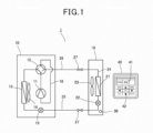
- FIG. 1 is a refrigeration cycle diagram illustrating the configuration of an air conditioner.
- an air conditioner 1 includes an outdoor unit 10 and an indoor unit 20.
- the outdoor unit 10 houses a compressor 11, a four-way valve 12 that switches refrigerant flow paths, an outdoor heat exchanger 13, an outdoor fan 14, and an outdoor throttle device 15, and these compressor 11, four-way valve 12, outdoor heat exchanger 13, and outdoor throttle device 15 are sequentially connected with a refrigerant pipe 16.
- the indoor unit 20 houses an indoor heat exchanger 21, an indoor throttle device 22, and an indoor fan 23, and the indoor heat exchanger 21 and the indoor throttle device 22 are connected via a refrigerant pipe 24.
- the compressor 11 of the outdoor unit 10 and the indoor heat exchanger 21 of the indoor unit 20 are connected with a liquid refrigerant pipe 25 and a gas refrigerant pipe 26.
- Each of the liquid refrigerant pipe 25 and the gas refrigerant pipe 26 has a refrigerant shut-off valve 27 at its intermediate portion.
- the indoor unit 20 houses a refrigerant sensor 30 for detecting leakage the refrigerant.
- the configuration may be such that the refrigerant sensor 30 is a unit separate from the indoor unit 20 and set in a place in the air conditioning space.
- a remote controller 40 for air conditioning operation is placed in the air conditioning space.
- the remote controller 40 includes a display section 41 and an operation section 42.
- the display section 41 shows specified representation, for example, the temperature set for the air conditioning space, the current room temperature, the operation type such as cooling, heating, dehumidification, or the like, the air direction, the time, and the like.
- the operation section 42 includes, for example, a plurality of operation switches, with which the set temperature, the operation type, the air flow rate, the air direction, and the like can be set.
- FIG. 2 is a block diagram illustrating the control configuration of the present embodiment.
- the air conditioner includes a control unit 50 and a storage unit 51.
- the control unit 50 for example, includes a processor such as a CPU and an MPU that executes programs and memory such as ROM and RAM, and the hardware and software cooperate to execute various processes such that the processor reads a control program stored in the memory and executes processes.
- a processor such as a CPU and an MPU that executes programs and memory such as ROM and RAM, and the hardware and software cooperate to execute various processes such that the processor reads a control program stored in the memory and executes processes.
- the control unit 50 based on the control program, according to operation on the remote controller 40, controls the compressor 11, the outdoor throttle device 15, and the outdoor fan 14 of the outdoor unit 10, and the indoor fan 23 and the indoor throttle device 22 of the indoor unit 20.
- the control unit 50 is configured to receive detection signals of the refrigerant sensor 30, and in the case in which the refrigerant sensor 30 detects leakage of the refrigerant, the control unit 50, for example, performs control to stop the compressor 11 and close the refrigerant shut-off valves 27.
- the storage unit 51 stores, for example, information sent from the remote controller 40.
- the control unit 50 counts the energization time of the refrigerant sensor 30, calculates the cumulative energization time, and stores it in the storage unit 51.
- the control unit 50 based on the cumulative energization time of the refrigerant sensor 30, makes a warning notification on the remote controller 40.
- the control unit 50 determines whether the cumulative energization time of the refrigerant sensor 30 has reached a first reference time.
- the first reference time is a specified time before the cumulative energization time of the refrigerant sensor 30 reaches its service life. Specifically, for example, in the case in which the service life of the refrigerant sensor 30 is five years, the first reference time is set to 60 days before the service life. The first reference time may be set as appropriate.
- control unit 50 determines that the cumulative energization time of the refrigerant sensor 30 has reached the first reference time, the control unit 50 performs control to make a warning notification in a first mode on the remote controller 40.
- the warning notification in the first mode for example, indicates an error code and an inspection display calling for inspection in a flashing manner.
- control unit 50 controls to stop the air conditioning operation. Since the user is thought to tend to check the remote controller 40 when the control unit 50 stops air conditioning operation as above, it is more likely that the user will recognize that the service life of the refrigerant sensor 30 has been reached.
- control unit 50 performs control in a second mode that only indicates inspection display in a flashing manner without indicating the error code.
- control unit 50 stops the air conditioning operation and performs control to make a warning notification in the first mode on the remote controller 40.
- the first period is set to, for example, seven days.
- the first period may be set as appropriate.
- control unit 50 performs control such that the remote controller 40 will make a warning notification in the second mode.
- This operation causes the user to check the remote controller 40, and this makes it more likely for the user to recognize that the service life of the refrigerant sensor 30 is coming.
- control in the present embodiment is performed such that air conditioning operation is stopped when the first reference time has passed, but the configuration may be such that when the first reference time has passed, the control unit 50 performs control so as to make only a warning notification on the remote controller 40 and continue the air conditioning operation. This is because if the air conditioning operation is stopped, there is a possibility the user's comfort can be impaired. This is also because the service life of the refrigerant sensor 30 has not come yet and hence continuing the air conditioning operation will not cause a problem.
- the configuration may be such that after the first reference time has passed, and when notification time has come, the control unit 50 performs control so as to stop the air conditioning operation under conditions in which the user's comfort would not be impaired.
- the notification time is, for example, the time when the first period has passed after operation is resumed.
- the cases in which the user's comfort would not be impaired means, for example, cases in which the temperature difference between the temperature set by the remote controller 40 and the room temperature or the outdoor temperature is within a specified value. Specifically, in winter, it may be the daytime, and in summer, it may be early morning or evening.
- the control may be performed so as to make, in addition to the warning notification on the remote controller 40, a warning notification by the refrigerant sensor 30.
- Such control makes it more likely for the user to recognize that the service life of the refrigerant sensor 30 is coming.
- the control may be performed so as not to make a warning notification by the refrigerant sensor 30.
- the warning notification for the case in which the first reference time has passed may be made by a central management center that manages the air conditioner.
- the control unit 50 determines whether the cumulative energization time of the refrigerant sensor 30 has reached a second reference time, and in the case in which the control unit 50 determines that the cumulative energization time of the refrigerant sensor 30 has reached the second reference time, the control unit 50 performs control so as to stop the air conditioning operation and make a warning notification in the first mode on the remote controller 40.
- the second reference time is the service life of the refrigerant sensor 30. In the case in which the service life of the refrigerant sensor 30 is five years, the second reference time is five years.
- control unit 50 performs control in a second mode that does not indicate the error code but only indicates inspection display in a flashing manner.
- control unit 50 After the second reference time has passed, when a specified second period has passed, the control unit 50 performs control so as to stop the air conditioning operation and make a warning notification in the first mode on the remote controller 40.
- the second period is set to, for example, one day.
- the second set time may be set as appropriate.
- control unit 50 performs control so as to make a warning notification in the second mode on the remote controller 40.
- This operation causes the user to check the remote controller 40, and this makes it more likely for the user to recognize that the service life of the refrigerant sensor 30 has come.
- control unit 50 performs control so as to prohibit the operation of the air conditioner.
- the third reference time is intended to be a longer time than the second reference time, and for example, the third reference time is set within a range from six months to two years or so longer than the service life of the refrigerant sensor 30.
- control unit 50 detects a special operation on the remote controller 40 or the like, the control unit 50 can reset the cumulative energization time of the refrigerant sensor 30.
- the special operation on the remote controller 40 or the like is, for example, an operation of pressing a plurality of buttons on the remote controller at the same time continuously for a specified time, or the like.
- control unit 50 receives a detection signal indicating leakage of the refrigerant from the refrigerant sensor 30, the control unit 50 stops the compressor 11, stops the air conditioning operation, and rotationally drives the indoor fan 23. This operation agitates the refrigerant leaked in the air conditioning space. After that, the control unit 50 performs control so as not to permit resumption of air conditioning operation until the control unit 50 detects that the circuit breaker is turned on after it is turned off and also detects a special operation on the remote controller 40 or the like.
- control unit 50 When the control unit 50 detects an irregular state of the refrigerant sensor 30, the control unit 50 stops the compressor 11 and stops the air conditioning operation.
- An irregular state of the refrigerant sensor 30 is, for example, a state in which the voltage value of the refrigerant sensor 30 is an irregular value, or the like.
- the control unit 50 After the control unit 50 detects an irregular state of the refrigerant sensor 30, the control unit 50 performs control so as not to permit resumption of air conditioning operation until the control unit 50 detects the circuit breaker is turned on after it is turned off.
- the conditions for resuming the air conditioning operation from the state in which the air conditioning operation is stopped are set such that the condition for the case in which the leakage of the refrigerant is detected is the strictest, the condition for the case in which an irregular state of the refrigerant sensor 30 is detected is the second strictest, and the condition for the case in which the service life of the refrigerant sensor 30 is detected is the least strict.
- FIGS. 3A to 3D are explanatory diagrams illustrating examples of warning notifications on the remote controller 40 in air conditioning operation.
- the display section 41 in air conditioning operation displays specified information such as the set temperature and the operation mode.
- the air conditioning operation is stopped, and as illustrated in FIG. 3B , a warning 60 that calls for inspection and indicates the error code is displayed, which is a warning notification in the first mode.
- FIG. 4 is a flowchart showing the operation of Embodiment 1.
- control unit 50 starts counting the cumulative energization time of the refrigerant sensor 30 (ST1).
- the control unit 50 determines whether the cumulative energization time of the refrigerant sensor 30 has reached the first reference time (ST2).
- control unit 50 determines that the cumulative energization time of the refrigerant sensor 30 has reached the first reference time (ST2: YES), the control unit 50 stops air conditioning operation and makes a warning notification in the first mode that calls for inspection and indicates the error code (ST3).
- control unit 50 resumes air conditioning operation and makes an alert notification in the second mode that only displays a waring 60 calling for inspection (ST5).
- the control unit 50 determines whether the cumulative energization time of the refrigerant sensor 30 has reached the second reference time (ST7), and if the control unit 50 determines that the cumulative energization time has reached the second reference time (ST7: YES), the control unit 50 stops air conditioning operation and makes a warning notification in the first mode that calls for inspection and indicates the error code (ST8).
- control unit 50 resumes air conditioning operation and makes an alert notification in the second mode that only displays a warning 60 calling for inspection (ST10).
- control unit 50 determines that the cumulative energization time of the refrigerant sensor 30 has reached the third reference time (ST12: YES). Then, in the case in which the control unit 50 determines that the cumulative energization time of the refrigerant sensor 30 has reached the third reference time (ST12: YES), the control unit 50 performs control so as to prohibit the operation of the air conditioner (ST13).
- an air conditioner of the present embodiment including an outdoor unit 10, an indoor unit 20 that is connected to the outdoor unit 10 via a refrigerant pipe and performs air conditioning in an air conditioning space, a refrigerant sensor 30 that detects leakage, in the air conditioning space, of refrigerant, and a remote controller 40 for operating air conditioning operation includes a control unit 50 that, in a case in which the cumulative energization time of the refrigerant sensor 30 has reached a reference time, performs control so as to make a warning notification on the remote controller 40 and stop air conditioning operation at specified intervals.
- the control unit 50 stops the air conditioning operation and makes, on the remote controller 40, a warning notification in a first mode indicating that the notification is a warning notification on the service life of the refrigerant sensor 30, and in a case in which air conditioning operation is resumed, the control unit 50 makes a warning notification in a second mode on the remote controller 40.
- the specified interval is longer when the cumulative energization time of the refrigerant sensor 30 has reached a first reference time than when the cumulative energization time of the refrigerant sensor 30 has reached a second reference time that is longer than the first reference time.
- the control unit 50 when the cumulative energization time of the refrigerant sensor 30 has reached a first reference time, the control unit 50 makes a warning notification on the remote controller 40 and continues the air conditioning operation and, when the cumulative energization time of the refrigerant sensor 30 has reached the second reference time which is longer than the first reference time, the control unit 50 performs control so as to make an alert notification on the remote controller 40 and stop air conditioning operation at specified intervals.
- the control unit 50 when the cumulative energization time of the refrigerant sensor 30 has reached a first reference time, the control unit 50 makes a warning notification on the remote controller 40, and in a case in which the cumulative energization time of the refrigerant sensor 30 has reached a notification time, and also the temperature difference between the set temperature and the room temperature is smaller than or equal to a specified value, the control unit 50 stops the air conditioning operation, and when the cumulative energization time of the refrigerant sensor 30 has reached a second reference time that is longer than the first reference time, the control unit 50 performs control so as to stop air conditioning operation when the cumulative energization time of the refrigerant sensor 30 has reached a notification time.
- stopping air conditioning operation as above may impair the user's comfort
- air conditioning operation without impairing the user's comfort is possible by stopping air conditioning operation under the condition that the temperature difference between the set temperature and the room temperature is lower than or equal to a specified value, and that the users' comfort would not be impaired.
- the cumulative energization time has reached the second reference time
- the cumulative energization time exceeded the service life of the refrigerant sensor 30, and thus, an alert notification including stopping the air conditioning operation is made at short specified intervals, so that the user can be aware of the alert notification.
- the control unit 50 prohibits air conditioning operation.
- Embodiment 1 has been described as an example of a technique disclosed in the present application.
- the technique in the present disclosure is not limited to this embodiment, but the technique in the present disclosure can also be applied to embodiments including changes, replacement, addition, and omission.
- new embodiments may be made by combining components described in the above Embodiment 1.
- Embodiment 1 describes the control to indicate an error code and inspection display calling for inspection in a flashing manner as an example of a warning notification in the first mode
- the present disclosure is not limited to this example.
- only an error code may be displayed, or something explicitly indicating an error related to the service life of the refrigerant sensor 30 may be displayed.
- it only needs to be a display mode that allows maintenance providers or users to realize that a warning notification related to the service life of the refrigerant sensor 30 was made.
- Embodiment 1 describes the control to indicate only inspection display in a flashing manner without indicating an error code, as an example of a warning notification in the second mode, the present disclosure is not limited to this example. For example, it may be continuously lit inspection display or the like.
- Embodiment 1 describes the configuration in which after the cumulative energization time of the refrigerant sensor 30 has reached the first reference time, the second reference time, the first elapsed time, or the second elapsed time, a first warning notification is made, and air conditioning operation is stopped, and after that, when air conditioning operation is resumed, a second warning notification is made, but the present disclosure is not limited to this example.
- the way of the warning notification for the case in which the cumulative energization time of the refrigerant sensor 30 has reached the first reference time or the second reference time and the way of the warning notification for the case in which air conditioning operation is resumed may be the same.
- Embodiment 1 describes that the second reference time is the service life time of the refrigerant sensor 30, and that the third reference time is a time longer than the service life time of the refrigerant sensor 30.
- the present disclosure is not limited to this example.
- the second reference time may be shorter than the service life time of the refrigerant sensor 30, and the third reference time may be the service life time of the refrigerant sensor 30.
- a configuration may be such that the first reference time is 60 days shorter than the service life time of the refrigerant sensor 30, the second reference time is 10 days shorter than the service life time of the refrigerant sensor 30, and the third reference time is the service life time of the refrigerant sensor 30.
- Embodiment 1 has a configuration in which the outdoor unit 10, the indoor unit 20, the remote controller 40, and the refrigerant sensor 30 are controlled by the one control unit 50
- the configuration may include an outdoor control unit that controls the outdoor unit 10, an indoor control unit that controls the indoor unit 20, a remote-controller control unit that controls the remote controller 40, and a sensor control unit that controls the refrigerant sensor 30, and the indoor control unit may count the cumulative energization time of the refrigerant sensor 30 and perform control to make warning notifications on the remote controller 40.
- the configuration may be such that the sensor control unit counts the cumulative energization time of the refrigerant sensor 30, and that the remote-controller control unit performs control to make warning notifications based on the cumulative energization time from the sensor control unit.
- an air conditioner according to the present disclosure when the cumulative energization time of the refrigerant sensor has reached the reference time, makes an alert notification on a remote controller and also stop the air conditioning operation, the stoppage of the air conditioning operation allows the user to be more easily aware of the alert notification on the remote controller, and the user can take measures on the service life of the refrigerant sensor, so that the air conditioner according to the present disclosure can be suitably used with improved safety.
Landscapes
- Engineering & Computer Science (AREA)
- Chemical & Material Sciences (AREA)
- Combustion & Propulsion (AREA)
- Mechanical Engineering (AREA)
- General Engineering & Computer Science (AREA)
- Human Computer Interaction (AREA)
- Physics & Mathematics (AREA)
- Signal Processing (AREA)
- Thermal Sciences (AREA)
- Fuzzy Systems (AREA)
- Mathematical Physics (AREA)
- Life Sciences & Earth Sciences (AREA)
- Sustainable Development (AREA)
- Air Conditioning Control Device (AREA)
Abstract
Description
- The present disclosure relates to air conditioners.
- As a conventional technique,
Japanese Patent No. 6656490 - The present disclosure provides an air conditioner that allows the user to be more easily aware of the service life of the refrigerant sensor and thus has improved safety.
- An air conditioner according to the present disclosure is an air conditioner including an outdoor unit, an indoor unit that is connected to the outdoor unit via a refrigerant pipe and performs air conditioning in an air conditioning space, a refrigerant sensor that detects leakage, in the air conditioning space, of refrigerant, and a remote controller for operating air conditioning operation, the air conditioner including a control unit that, in a case in which the cumulative energization time of the refrigerant sensor has reached a reference time, performs control so as to make a warning notification on the remote controller and stop air conditioning operation.
- In the present disclosure, when the cumulative energization time of the refrigerant sensor has reached the reference time, an alert notification is made on a remote controller, and also the air conditioning operation is stopped, and thus, the user is more easily aware of the alert notification on the remote controller because of the stoppage of the air conditioning operation. Thus, the user can take measures on the service life of the refrigerant sensor such as making contact with a maintenance provider, and this leads to improvement of the safety.
-
-
FIG. 1 is a refrigeration cycle diagram illustrating the configuration of an air conditioner inEmbodiment 1; -
FIG. 2 is a block diagram illustrating the control configuration ofEmbodiment 1; -
FIGS. 3A to 3D are explanatory diagrams illustrating examples of warning notifications on a remote controller in air conditioning operation; and -
FIG. 4 is a flowchart showing the operation ofEmbodiment 1. - At the time when the inventors conceived the present disclosure, there was a technique in which a pre-event notification is made before the cumulative energization time of the refrigerant sensor reaches the service life time of the refrigerant sensor, a post-event notification is made when the cumulative energization time has reached the service life time of the refrigerant sensor, and when the refrigerant sensor failed after the cumulative energization time had exceeded the service life time of the refrigerant sensor, a notification on the service life of the refrigerant sensor is made, and then, the air conditioning operation is stopped.
- However, although the conventional technique includes a pre-event notification, a service-life-time notification, and a post-event notification regarding the service life of the refrigerant sensor, there is possibility that just notifying the service life of the refrigerant sensor cannot allow the user to be aware of the notification, and the inventors having realized this problem constructed the subject matter of the present disclosure to solve the problem.
- The present disclosure provides an air conditioner that allows the user to be more easily aware of the service life of the refrigerant sensor and thus has improved safety.
- Hereinafter, an embodiment will be described in detail with reference to the drawings. However, detailed description may be omitted if it is not necessary. For example, detailed description of already well known matters and repetitive description of substantially the same configurations may be omitted. This is to avoid the following description becoming unnecessarily lengthy and to help those skilled in the art understand the disclosure more easily.
- Note that the attached drawings and the following description are provided to help those skilled in the art fully understand the present disclosure and hence not intended to limit the subject matter described in the claims.
- Hereinafter,
Embodiment 1 will be described with reference toFIGS. 1 and2 . - First, the configuration of an air conditioner will be described.
-
FIG. 1 is a refrigeration cycle diagram illustrating the configuration of an air conditioner. - As illustrated in
FIG. 1 , anair conditioner 1 includes anoutdoor unit 10 and anindoor unit 20. Theoutdoor unit 10 houses acompressor 11, a four-way valve 12 that switches refrigerant flow paths, anoutdoor heat exchanger 13, anoutdoor fan 14, and anoutdoor throttle device 15, and thesecompressor 11, four-way valve 12,outdoor heat exchanger 13, andoutdoor throttle device 15 are sequentially connected with arefrigerant pipe 16. - The
indoor unit 20 houses anindoor heat exchanger 21, anindoor throttle device 22, and anindoor fan 23, and theindoor heat exchanger 21 and theindoor throttle device 22 are connected via arefrigerant pipe 24. - The
compressor 11 of theoutdoor unit 10 and theindoor heat exchanger 21 of theindoor unit 20 are connected with aliquid refrigerant pipe 25 and agas refrigerant pipe 26. - Each of the
liquid refrigerant pipe 25 and thegas refrigerant pipe 26 has a refrigerant shut-offvalve 27 at its intermediate portion. - The
indoor unit 20 houses arefrigerant sensor 30 for detecting leakage the refrigerant. Note that the configuration may be such that therefrigerant sensor 30 is a unit separate from theindoor unit 20 and set in a place in the air conditioning space. - A
remote controller 40 for air conditioning operation is placed in the air conditioning space. Theremote controller 40 includes adisplay section 41 and anoperation section 42. - The
display section 41 shows specified representation, for example, the temperature set for the air conditioning space, the current room temperature, the operation type such as cooling, heating, dehumidification, or the like, the air direction, the time, and the like. - The
operation section 42 includes, for example, a plurality of operation switches, with which the set temperature, the operation type, the air flow rate, the air direction, and the like can be set. - Next, the control configuration of the present embodiment will be described.
-
FIG. 2 is a block diagram illustrating the control configuration of the present embodiment. - As illustrated in
FIG. 2 , the air conditioner includes acontrol unit 50 and astorage unit 51. - The
control unit 50, for example, includes a processor such as a CPU and an MPU that executes programs and memory such as ROM and RAM, and the hardware and software cooperate to execute various processes such that the processor reads a control program stored in the memory and executes processes. - The
control unit 50, based on the control program, according to operation on theremote controller 40, controls thecompressor 11, theoutdoor throttle device 15, and theoutdoor fan 14 of theoutdoor unit 10, and theindoor fan 23 and theindoor throttle device 22 of theindoor unit 20. - The
control unit 50 is configured to receive detection signals of therefrigerant sensor 30, and in the case in which therefrigerant sensor 30 detects leakage of the refrigerant, thecontrol unit 50, for example, performs control to stop thecompressor 11 and close the refrigerant shut-offvalves 27. - The
storage unit 51 stores, for example, information sent from theremote controller 40. In addition, thecontrol unit 50 counts the energization time of therefrigerant sensor 30, calculates the cumulative energization time, and stores it in thestorage unit 51. - The
control unit 50, based on the cumulative energization time of therefrigerant sensor 30, makes a warning notification on theremote controller 40. - The
control unit 50 determines whether the cumulative energization time of therefrigerant sensor 30 has reached a first reference time. The first reference time is a specified time before the cumulative energization time of therefrigerant sensor 30 reaches its service life. Specifically, for example, in the case in which the service life of therefrigerant sensor 30 is five years, the first reference time is set to 60 days before the service life. The first reference time may be set as appropriate. - In the case in which the
control unit 50 determines that the cumulative energization time of therefrigerant sensor 30 has reached the first reference time, thecontrol unit 50 performs control to make a warning notification in a first mode on theremote controller 40. - The warning notification in the first mode, for example, indicates an error code and an inspection display calling for inspection in a flashing manner.
- Then, the
control unit 50 controls to stop the air conditioning operation. Since the user is thought to tend to check theremote controller 40 when thecontrol unit 50 stops air conditioning operation as above, it is more likely that the user will recognize that the service life of therefrigerant sensor 30 has been reached. - After that, in the case in which the user operates the
operation section 42 of theremote controller 40 to resume air conditioning operation, thecontrol unit 50 performs control in a second mode that only indicates inspection display in a flashing manner without indicating the error code. - After the first reference time has passed, when a specified first set period has passed, the
control unit 50 stops the air conditioning operation and performs control to make a warning notification in the first mode on theremote controller 40. - Here, the first period is set to, for example, seven days. The first period may be set as appropriate.
- Then, in the case in which the air conditioning operation is resumed, the
control unit 50 performs control such that theremote controller 40 will make a warning notification in the second mode. - These operations are repeated at first intervals. This operation causes the user to check the
remote controller 40, and this makes it more likely for the user to recognize that the service life of therefrigerant sensor 30 is coming. - Note that the control in the present embodiment is performed such that air conditioning operation is stopped when the first reference time has passed, but the configuration may be such that when the first reference time has passed, the
control unit 50 performs control so as to make only a warning notification on theremote controller 40 and continue the air conditioning operation. This is because if the air conditioning operation is stopped, there is a possibility the user's comfort can be impaired. This is also because the service life of therefrigerant sensor 30 has not come yet and hence continuing the air conditioning operation will not cause a problem. - Alternatively, the configuration may be such that after the first reference time has passed, and when notification time has come, the
control unit 50 performs control so as to stop the air conditioning operation under conditions in which the user's comfort would not be impaired. With this configuration, it is possible to prevent or reduce impairment in the user's comfort. The notification time is, for example, the time when the first period has passed after operation is resumed. The cases in which the user's comfort would not be impaired means, for example, cases in which the temperature difference between the temperature set by theremote controller 40 and the room temperature or the outdoor temperature is within a specified value. Specifically, in winter, it may be the daytime, and in summer, it may be early morning or evening. - Note that in the case in which the
refrigerant sensor 30 is a unit separate from theindoor unit 20 and set in the air conditioning space, the control may be performed so as to make, in addition to the warning notification on theremote controller 40, a warning notification by therefrigerant sensor 30. Such control makes it more likely for the user to recognize that the service life of therefrigerant sensor 30 is coming. In the case in which therefrigerant sensor 30 is included in theindoor unit 20, the control may be performed so as not to make a warning notification by therefrigerant sensor 30. - The warning notification for the case in which the first reference time has passed may be made by a central management center that manages the air conditioner.
- The
control unit 50 determines whether the cumulative energization time of therefrigerant sensor 30 has reached a second reference time, and in the case in which thecontrol unit 50 determines that the cumulative energization time of therefrigerant sensor 30 has reached the second reference time, thecontrol unit 50 performs control so as to stop the air conditioning operation and make a warning notification in the first mode on theremote controller 40. - The second reference time is the service life of the
refrigerant sensor 30. In the case in which the service life of therefrigerant sensor 30 is five years, the second reference time is five years. - After that, in the case in which the user operates the
operation section 42 of theremote controller 40 to resume air conditioning operation, thecontrol unit 50 performs control in a second mode that does not indicate the error code but only indicates inspection display in a flashing manner. - After the second reference time has passed, when a specified second period has passed, the
control unit 50 performs control so as to stop the air conditioning operation and make a warning notification in the first mode on theremote controller 40. - Here, the second period is set to, for example, one day. The second set time may be set as appropriate.
- In the case in which the air conditioning operation is resumed, the
control unit 50 performs control so as to make a warning notification in the second mode on theremote controller 40. - These operations are repeated at second intervals. This operation causes the user to check the
remote controller 40, and this makes it more likely for the user to recognize that the service life of therefrigerant sensor 30 has come. - In addition, in the case in which a third reference time has passed, the
control unit 50 performs control so as to prohibit the operation of the air conditioner. - The third reference time is intended to be a longer time than the second reference time, and for example, the third reference time is set within a range from six months to two years or so longer than the service life of the
refrigerant sensor 30. - When the third reference time has passed, the operation of the air conditioner is prohibited for safety reasons because there is no guarantee that the
refrigerant sensor 30 will operate normally. - In the case in which the
control unit 50 detects a special operation on theremote controller 40 or the like, thecontrol unit 50 can reset the cumulative energization time of therefrigerant sensor 30. The special operation on theremote controller 40 or the like is, for example, an operation of pressing a plurality of buttons on the remote controller at the same time continuously for a specified time, or the like. - In the case in which the
control unit 50 receives a detection signal indicating leakage of the refrigerant from therefrigerant sensor 30, thecontrol unit 50 stops thecompressor 11, stops the air conditioning operation, and rotationally drives theindoor fan 23. This operation agitates the refrigerant leaked in the air conditioning space. After that, thecontrol unit 50 performs control so as not to permit resumption of air conditioning operation until thecontrol unit 50 detects that the circuit breaker is turned on after it is turned off and also detects a special operation on theremote controller 40 or the like. In other words, since the control is performed so as not to allow resumption of air conditioning operation until the above operation is performed, it is possible to prevent air conditioning operation from being resumed arbitrarily by the user's operation without an appropriate measure against the leakage of the refrigerant. - When the
control unit 50 detects an irregular state of therefrigerant sensor 30, thecontrol unit 50 stops thecompressor 11 and stops the air conditioning operation. An irregular state of therefrigerant sensor 30 is, for example, a state in which the voltage value of therefrigerant sensor 30 is an irregular value, or the like. After thecontrol unit 50 detects an irregular state of therefrigerant sensor 30, thecontrol unit 50 performs control so as not to permit resumption of air conditioning operation until thecontrol unit 50 detects the circuit breaker is turned on after it is turned off. - In other words, since the control is performed so as not to permit resumption of air conditioning operation until the above operation is performed, it is possible to prevent air conditioning operation from being resumed arbitrarily by the user's operation in the state in which inspection or replacement of the
refrigerant sensor 30 have not been made. - Because the importance of safety measures is in the order of detection of the leakage of the refrigerant, detection of an irregular state of the
refrigerant sensor 30, and the state of the service life of therefrigerant sensor 30, the conditions for resuming the air conditioning operation from the state in which the air conditioning operation is stopped are set such that the condition for the case in which the leakage of the refrigerant is detected is the strictest, the condition for the case in which an irregular state of therefrigerant sensor 30 is detected is the second strictest, and the condition for the case in which the service life of therefrigerant sensor 30 is detected is the least strict. This configuration makes it possible to achieve both the convenience and safety of the user. -
FIGS. 3A to 3D are explanatory diagrams illustrating examples of warning notifications on theremote controller 40 in air conditioning operation. - As illustrated in
FIG. 3A , thedisplay section 41 in air conditioning operation displays specified information such as the set temperature and the operation mode. - Then, in the case in which the cumulative energization time of the
refrigerant sensor 30 has reached the first reference time or the second reference time, the air conditioning operation is stopped, and as illustrated inFIG. 3B , a warning 60 that calls for inspection and indicates the error code is displayed, which is a warning notification in the first mode. - In the case in which the "ON/OFF" button is operated in the state of
FIG. 3B , and air conditioning operation is resumed, as illustrated inFIG. 3C , only awarning 60 calling for inspection is displayed in a flashing manner, which is a warning notification in the second mode. - Then, in the state in which the "ON/OFF" button is operated in the state of
FIG. 3C , and the air conditioning operation is stopped, as illustrated inFIG. 3D , awarning 60 calling for inspection is displayed in a flashing manner. - Next, the operation of the present embodiment will be described.
-
FIG. 4 is a flowchart showing the operation ofEmbodiment 1. - When the air conditioner is installed, the
control unit 50 starts counting the cumulative energization time of the refrigerant sensor 30 (ST1). - The
control unit 50 determines whether the cumulative energization time of therefrigerant sensor 30 has reached the first reference time (ST2). - If the
control unit 50 determines that the cumulative energization time of therefrigerant sensor 30 has reached the first reference time (ST2: YES), thecontrol unit 50 stops air conditioning operation and makes a warning notification in the first mode that calls for inspection and indicates the error code (ST3). - Then, in the case in which air conditioning operation is turned on by operation on the remote controller 40 (ST4: YES), the
control unit 50 resumes air conditioning operation and makes an alert notification in the second mode that only displays a waring 60 calling for inspection (ST5). - When the first period has passed since the operation was resumed (ST6: YES), the air conditioning operation is stopped, and an alert notification is made in the first mode (ST3). This operation is repeated every time the first period passes.
- The
control unit 50 determines whether the cumulative energization time of therefrigerant sensor 30 has reached the second reference time (ST7), and if thecontrol unit 50 determines that the cumulative energization time has reached the second reference time (ST7: YES), thecontrol unit 50 stops air conditioning operation and makes a warning notification in the first mode that calls for inspection and indicates the error code (ST8). - Then, in the case in which air conditioning operation is turned on by operation on the remote controller 40 (ST9: YES), the
control unit 50 resumes air conditioning operation and makes an alert notification in the second mode that only displays awarning 60 calling for inspection (ST10). - When the second period has passed since the operation was resumed (ST11: YES), the air conditioning operation is stopped, and an alert notification is made in the first mode (ST8). This operation is repeated every time the second period passes.
- Then, in the case in which the
control unit 50 determines that the cumulative energization time of therefrigerant sensor 30 has reached the third reference time (ST12: YES), thecontrol unit 50 performs control so as to prohibit the operation of the air conditioner (ST13). - As has been described above, an air conditioner of the present embodiment including an
outdoor unit 10, anindoor unit 20 that is connected to theoutdoor unit 10 via a refrigerant pipe and performs air conditioning in an air conditioning space, arefrigerant sensor 30 that detects leakage, in the air conditioning space, of refrigerant, and aremote controller 40 for operating air conditioning operation includes acontrol unit 50 that, in a case in which the cumulative energization time of therefrigerant sensor 30 has reached a reference time, performs control so as to make a warning notification on theremote controller 40 and stop air conditioning operation at specified intervals. - With this configuration, when the cumulative energization time of the
refrigerant sensor 30 has reached the reference time, an alert notification is made on aremote controller 40, and also the air conditioning operation is stopped, and thus, the user is more easily aware of the alert notification on theremote controller 40 because of the stoppage of the air conditioning operation. Thus, the user can take measures on the service life of therefrigerant sensor 30 such as making contact with a maintenance provider, and this leads to improvement of the safety. - In the present embodiment, when the cumulative energization time of the
refrigerant sensor 30 has reached the reference time, thecontrol unit 50 stops the air conditioning operation and makes, on theremote controller 40, a warning notification in a first mode indicating that the notification is a warning notification on the service life of therefrigerant sensor 30, and in a case in which air conditioning operation is resumed, thecontrol unit 50 makes a warning notification in a second mode on theremote controller 40. - With this configuration, it is possible to indicate a warning calling for inspection of the
refrigerant sensor 30 and the error code on theremote controller 40 when stopping the air conditioning operation, and thus, the error code can be checked only when the air conditioning operation is stopped, and the user checks theremote controller 40. Then, in the case in which air conditioning operation is resumed, displaying only the warning in a flashing manner enables the user to recognize that inspection is necessary. - In the present embodiment, the specified interval is longer when the cumulative energization time of the
refrigerant sensor 30 has reached a first reference time than when the cumulative energization time of therefrigerant sensor 30 has reached a second reference time that is longer than the first reference time. - With this configuration, since there is some time until the service life of the
refrigerant sensor 30 when the cumulative energization time reaches the first reference time which is shorter than the service life of therefrigerant sensor 30, it is possible to prevent impairment of the user's convenience by making a warning notification including stopping the air conditioning operation at longer specified intervals. In contrast, when the cumulative energization time has reached the second reference time, the cumulative energization time exceeded the service life of therefrigerant sensor 30, and thus, an alert notification including stopping the air conditioning is made at short specified intervals, so that the user will be more easily aware of the alert notification. In other words, this makes it possible to achieve both the convenience and safety of the user. - In the present embodiment, when the cumulative energization time of the
refrigerant sensor 30 has reached a first reference time, thecontrol unit 50 makes a warning notification on theremote controller 40 and continues the air conditioning operation and, when the cumulative energization time of therefrigerant sensor 30 has reached the second reference time which is longer than the first reference time, thecontrol unit 50 performs control so as to make an alert notification on theremote controller 40 and stop air conditioning operation at specified intervals. - With this configuration, since stopping air conditioning operation may impair the user's comfort, control to stop the air conditioning operation is not performed until the cumulative energization time exceeds the second reference time, and this makes it possible to keep the user's comfort. In contrast, when the cumulative energization time has reached the second reference time, the cumulative energization time exceeded the service life of the
refrigerant sensor 30, and thus, an alert notification including stopping the air conditioning operation is made at short specified intervals, so that the user can be aware of the alert notification. In other words, this makes it possible to achieve both the convenience and safety of the user. - In the present embodiment, when the cumulative energization time of the
refrigerant sensor 30 has reached a first reference time, thecontrol unit 50 makes a warning notification on theremote controller 40, and in a case in which the cumulative energization time of therefrigerant sensor 30 has reached a notification time, and also the temperature difference between the set temperature and the room temperature is smaller than or equal to a specified value, thecontrol unit 50 stops the air conditioning operation, and when the cumulative energization time of therefrigerant sensor 30 has reached a second reference time that is longer than the first reference time, thecontrol unit 50 performs control so as to stop air conditioning operation when the cumulative energization time of therefrigerant sensor 30 has reached a notification time. - Although stopping air conditioning operation as above may impair the user's comfort, air conditioning operation without impairing the user's comfort is possible by stopping air conditioning operation under the condition that the temperature difference between the set temperature and the room temperature is lower than or equal to a specified value, and that the users' comfort would not be impaired. In contrast, when the cumulative energization time has reached the second reference time, the cumulative energization time exceeded the service life of the
refrigerant sensor 30, and thus, an alert notification including stopping the air conditioning operation is made at short specified intervals, so that the user can be aware of the alert notification. - In the present embodiment, when the cumulative energization time of the
refrigerant sensor 30 has reached a third reference time that is longer than the second reference time, thecontrol unit 50 prohibits air conditioning operation. - With this configuration, since air conditioning operation is prohibited in the case in which the cumulative energization time of the
refrigerant sensor 30 has reached the third reference time which is longer than the service life of therefrigerant sensor 30, air conditioning operation in the state in which therefrigerant sensor 30 may not perform normally is prohibited, and this operation improves the safety. - As above,
Embodiment 1 has been described as an example of a technique disclosed in the present application. - However, the technique in the present disclosure is not limited to this embodiment, but the technique in the present disclosure can also be applied to embodiments including changes, replacement, addition, and omission. In addition, new embodiments may be made by combining components described in the
above Embodiment 1. - Although
Embodiment 1 describes the control to indicate an error code and inspection display calling for inspection in a flashing manner as an example of a warning notification in the first mode, the present disclosure is not limited to this example. For example, only an error code may be displayed, or something explicitly indicating an error related to the service life of therefrigerant sensor 30 may be displayed. In short, it only needs to be a display mode that allows maintenance providers or users to realize that a warning notification related to the service life of therefrigerant sensor 30 was made. - Although
Embodiment 1 describes the control to indicate only inspection display in a flashing manner without indicating an error code, as an example of a warning notification in the second mode, the present disclosure is not limited to this example. For example, it may be continuously lit inspection display or the like. -
Embodiment 1 describes the configuration in which after the cumulative energization time of therefrigerant sensor 30 has reached the first reference time, the second reference time, the first elapsed time, or the second elapsed time, a first warning notification is made, and air conditioning operation is stopped, and after that, when air conditioning operation is resumed, a second warning notification is made, but the present disclosure is not limited to this example. The way of the warning notification for the case in which the cumulative energization time of therefrigerant sensor 30 has reached the first reference time or the second reference time and the way of the warning notification for the case in which air conditioning operation is resumed may be the same. -
Embodiment 1 describes that the second reference time is the service life time of therefrigerant sensor 30, and that the third reference time is a time longer than the service life time of therefrigerant sensor 30. However, the present disclosure is not limited to this example. For example, the second reference time may be shorter than the service life time of therefrigerant sensor 30, and the third reference time may be the service life time of therefrigerant sensor 30. As an example, a configuration may be such that the first reference time is 60 days shorter than the service life time of therefrigerant sensor 30, the second reference time is 10 days shorter than the service life time of therefrigerant sensor 30, and the third reference time is the service life time of therefrigerant sensor 30. - Although
Embodiment 1 has a configuration in which theoutdoor unit 10, theindoor unit 20, theremote controller 40, and therefrigerant sensor 30 are controlled by the onecontrol unit 50, the present disclosure is not limited to this example. For example, the configuration may include an outdoor control unit that controls theoutdoor unit 10, an indoor control unit that controls theindoor unit 20, a remote-controller control unit that controls theremote controller 40, and a sensor control unit that controls therefrigerant sensor 30, and the indoor control unit may count the cumulative energization time of therefrigerant sensor 30 and perform control to make warning notifications on theremote controller 40. - The configuration may be such that the sensor control unit counts the cumulative energization time of the
refrigerant sensor 30, and that the remote-controller control unit performs control to make warning notifications based on the cumulative energization time from the sensor control unit. - Since an air conditioner according to the present disclosure, when the cumulative energization time of the refrigerant sensor has reached the reference time, makes an alert notification on a remote controller and also stop the air conditioning operation, the stoppage of the air conditioning operation allows the user to be more easily aware of the alert notification on the remote controller, and the user can take measures on the service life of the refrigerant sensor, so that the air conditioner according to the present disclosure can be suitably used with improved safety.
-
- 1
- air conditioner
- 10
- outdoor unit
- 11
- compressor
- 12
- four-way valve
- 13
- outdoor heat exchanger
- 14
- outdoor fan
- 15
- outdoor throttle device
- 16
- refrigerant pipe
- 20
- indoor unit
- 21
- indoor heat exchanger
- 22
- indoor throttle device
- 23
- indoor fan
- 24
- refrigerant pipe
- 25
- liquid refrigerant pipe
- 26
- gas refrigerant pipe
- 27
- refrigerant shut-off valve
- 30
- refrigerant sensor
- 40
- remote controller
- 41
- display section
- 42
- operation section
- 50
- control unit
- 51
- storage unit
Claims (7)
- An air conditioner including an outdoor unit (10), an indoor unit (20) that is connected to the outdoor unit via a refrigerant pipe (16) and performs air conditioning in an air conditioning space, a refrigerant sensor (30) that detects leakage, in the air conditioning space, of refrigerant, and a remote controller (40) for operating air conditioning operation, the air conditioner characterized by comprising
a control unit (50) that, in a case in which the cumulative energization time of the refrigerant sensor has reached a reference time, performs control so as to make a warning notification on the remote controller and stop air conditioning operation at specified intervals. - The air conditioner according to claim 1, wherein
when the cumulative energization time of the refrigerant sensor has reached the reference time, the control unit stops the air conditioning operation and makes, on the remote controller, a warning notification in a first mode indicating that the notification is a warning notification on the service life of the refrigerant sensor, and in a case in which air conditioning operation is resumed, the control unit makes a warning notification in a second mode on the remote controller. - The air conditioner according to claim 1, wherein
the specified interval is longer when the cumulative energization time of the refrigerant sensor has reached a first reference time than when the cumulative energization time of the refrigerant sensor has reached a second reference time that is longer than the first reference time. - The air conditioner according to claim 1, whereinwhen the cumulative energization time of the refrigerant sensor has reached a first reference time, the control unit makes a warning notification on the remote controller and continues the air conditioning operation and,when the cumulative energization time of the refrigerant sensor has reached a second reference time that is longer than the first reference time, the control unit performs control so as to make an alert notification on the remote controller and stop air conditioning operation at specified intervals.
- The air conditioner according to claim 1, whereinwhen the cumulative energization time of the refrigerant sensor has reached a first reference time, the control unit makes a warning notification on the remote controller, and in a case in which the cumulative energization time of the refrigerant sensor has reached a notification time, and also the temperature difference between the set temperature and the room temperature is smaller than or equal to a specified value, the control unit stops the air conditioning operation, andwhen the cumulative energization time of the refrigerant sensor has reached a second reference time that is longer than the first reference time, the control unit performs control so as to stop air conditioning operation when the cumulative energization time of the refrigerant sensor has reached a notification time.
- The air conditioner according to any one of claims 3 to 5, whereinthe first reference time is shorter than the service life time of the refrigerant sensor, andthe second reference time is the service life time of the refrigerant sensor.
- The air conditioner according to claim 6, wherein
when the cumulative energization time of the refrigerant sensor has reached a third reference time that is longer than the second reference time, the control unit prohibits air conditioning operation.
Applications Claiming Priority (1)
| Application Number | Priority Date | Filing Date | Title |
|---|---|---|---|
| JP2022059268A JP7617516B2 (en) | 2022-03-31 | 2022-03-31 | Air Conditioning Equipment |
Publications (2)
| Publication Number | Publication Date |
|---|---|
| EP4253855A1 true EP4253855A1 (en) | 2023-10-04 |
| EP4253855B1 EP4253855B1 (en) | 2025-12-24 |
Family
ID=85704770
Family Applications (1)
| Application Number | Title | Priority Date | Filing Date |
|---|---|---|---|
| EP23162801.7A Active EP4253855B1 (en) | 2022-03-31 | 2023-03-20 | Air conditioner |
Country Status (3)
| Country | Link |
|---|---|
| EP (1) | EP4253855B1 (en) |
| JP (1) | JP7617516B2 (en) |
| CN (1) | CN116892754A (en) |
Citations (6)
| Publication number | Priority date | Publication date | Assignee | Title |
|---|---|---|---|---|
| JPH0356490B2 (en) | 1985-02-27 | 1991-08-28 | ||
| JP2011185547A (en) * | 2010-03-09 | 2011-09-22 | Sharp Corp | Service life management device, electric appliance and service life management method |
| EP3333509A1 (en) * | 2015-08-07 | 2018-06-13 | Mitsubishi Electric Corporation | Refrigeration cycle device and refrigeration cycle system |
| EP3460347A1 (en) * | 2016-05-18 | 2019-03-27 | Mitsubishi Electric Corporation | Air conditioner |
| WO2021177298A1 (en) * | 2020-03-02 | 2021-09-10 | ダイキン工業株式会社 | Equipment management system |
| WO2021234857A1 (en) * | 2020-05-20 | 2021-11-25 | ダイキン工業株式会社 | Refrigeration cycle device |
Family Cites Families (6)
| Publication number | Priority date | Publication date | Assignee | Title |
|---|---|---|---|---|
| JP2002039649A (en) * | 2000-07-24 | 2002-02-06 | Funai Electric Co Ltd | Operation alarm device of air conditioner |
| KR20110001667A (en) * | 2009-06-30 | 2011-01-06 | 엘지전자 주식회사 | Air conditioner and its operation method |
| JP2013079802A (en) * | 2012-12-26 | 2013-05-02 | Mitsubishi Electric Corp | Air conditioning device |
| JP2017053509A (en) * | 2015-09-08 | 2017-03-16 | ジョンソンコントロールズ ヒタチ エア コンディショニング テクノロジー(ホンコン)リミテッド | Air conditioning system and warning notification method for air conditioning system |
| WO2019116437A1 (en) | 2017-12-12 | 2019-06-20 | 日立ジョンソンコントロールズ空調株式会社 | Air conditioner |
| JP6678283B1 (en) * | 2018-11-30 | 2020-04-08 | 日立ジョンソンコントロールズ空調株式会社 | Leak detection device and leak detection system |
-
2022
- 2022-03-31 JP JP2022059268A patent/JP7617516B2/en active Active
-
2023
- 2023-03-20 EP EP23162801.7A patent/EP4253855B1/en active Active
- 2023-03-29 CN CN202310324925.0A patent/CN116892754A/en active Pending
Patent Citations (6)
| Publication number | Priority date | Publication date | Assignee | Title |
|---|---|---|---|---|
| JPH0356490B2 (en) | 1985-02-27 | 1991-08-28 | ||
| JP2011185547A (en) * | 2010-03-09 | 2011-09-22 | Sharp Corp | Service life management device, electric appliance and service life management method |
| EP3333509A1 (en) * | 2015-08-07 | 2018-06-13 | Mitsubishi Electric Corporation | Refrigeration cycle device and refrigeration cycle system |
| EP3460347A1 (en) * | 2016-05-18 | 2019-03-27 | Mitsubishi Electric Corporation | Air conditioner |
| WO2021177298A1 (en) * | 2020-03-02 | 2021-09-10 | ダイキン工業株式会社 | Equipment management system |
| WO2021234857A1 (en) * | 2020-05-20 | 2021-11-25 | ダイキン工業株式会社 | Refrigeration cycle device |
Also Published As
| Publication number | Publication date |
|---|---|
| JP2023150256A (en) | 2023-10-16 |
| EP4253855B1 (en) | 2025-12-24 |
| CN116892754A (en) | 2023-10-17 |
| JP7617516B2 (en) | 2025-01-20 |
Similar Documents
| Publication | Publication Date | Title |
|---|---|---|
| US4262736A (en) | Apparatus for heat pump malfunction detection | |
| CN103134142B (en) | Method for detecting complete blockage of air conditioning system | |
| US9535408B2 (en) | Control system for a room air conditioner and/or heat pump | |
| CN113587359B (en) | Control method and device for valve cut-off protection, controller and air conditioner | |
| CN109282424B (en) | Air conditioner control method and air conditioner control device | |
| CN106016459B (en) | Air conditioner and its control method | |
| JP6381824B2 (en) | Refrigeration cycle equipment | |
| US11913659B2 (en) | Systems and methods for monitoring operation of an HVAC system | |
| JP2002039649A (en) | Operation alarm device of air conditioner | |
| EP4253855A1 (en) | Air conditioner | |
| JP2000274773A (en) | Air conditioner control method | |
| EP3214384B1 (en) | Remote controller for air conditioning system | |
| JP3590499B2 (en) | Air conditioner | |
| JP2009145005A (en) | Control method of multi-room air conditioner | |
| JP2003166740A (en) | Air conditioner | |
| JP7522960B2 (en) | Air conditioners | |
| JP2007155226A (en) | Air conditioner | |
| CN108131776B (en) | Air conditioner fluorine deficiency protection method and air conditioner | |
| JP3119209B2 (en) | High pressure protection controller for refrigeration equipment | |
| JPH0486444A (en) | Air conditioner | |
| EP4656963A1 (en) | Air conditioner and control method | |
| JP2024146237A (en) | Refrigeration Cycle System | |
| CN111442471A (en) | Air conditioner, control method and control device thereof, and computer readable storage medium | |
| US20070130974A1 (en) | Air conditioner defrost system | |
| JP2024146274A (en) | Air Conditioning System |
Legal Events
| Date | Code | Title | Description |
|---|---|---|---|
| PUAI | Public reference made under article 153(3) epc to a published international application that has entered the european phase |
Free format text: ORIGINAL CODE: 0009012 |
|
| STAA | Information on the status of an ep patent application or granted ep patent |
Free format text: STATUS: THE APPLICATION HAS BEEN PUBLISHED |
|
| AK | Designated contracting states |
Kind code of ref document: A1 Designated state(s): AL AT BE BG CH CY CZ DE DK EE ES FI FR GB GR HR HU IE IS IT LI LT LU LV MC ME MK MT NL NO PL PT RO RS SE SI SK SM TR |
|
| STAA | Information on the status of an ep patent application or granted ep patent |
Free format text: STATUS: REQUEST FOR EXAMINATION WAS MADE |
|
| 17P | Request for examination filed |
Effective date: 20240404 |
|
| RBV | Designated contracting states (corrected) |
Designated state(s): AL AT BE BG CH CY CZ DE DK EE ES FI FR GB GR HR HU IE IS IT LI LT LU LV MC ME MK MT NL NO PL PT RO RS SE SI SK SM TR |
|
| GRAP | Despatch of communication of intention to grant a patent |
Free format text: ORIGINAL CODE: EPIDOSNIGR1 |
|
| STAA | Information on the status of an ep patent application or granted ep patent |
Free format text: STATUS: GRANT OF PATENT IS INTENDED |
|
| RIC1 | Information provided on ipc code assigned before grant |
Ipc: F25B 49/00 20060101ALI20250214BHEP Ipc: F25B 13/00 20060101ALI20250214BHEP Ipc: F24F 11/52 20180101ALI20250214BHEP Ipc: F24F 11/36 20180101ALI20250214BHEP Ipc: F24F 11/61 20180101ALI20250214BHEP Ipc: F24F 11/49 20180101AFI20250214BHEP |
|
| INTG | Intention to grant announced |
Effective date: 20250227 |
|
| GRAJ | Information related to disapproval of communication of intention to grant by the applicant or resumption of examination proceedings by the epo deleted |
Free format text: ORIGINAL CODE: EPIDOSDIGR1 |
|
| STAA | Information on the status of an ep patent application or granted ep patent |
Free format text: STATUS: REQUEST FOR EXAMINATION WAS MADE |
|
| GRAP | Despatch of communication of intention to grant a patent |
Free format text: ORIGINAL CODE: EPIDOSNIGR1 |
|
| STAA | Information on the status of an ep patent application or granted ep patent |
Free format text: STATUS: GRANT OF PATENT IS INTENDED |
|
| INTC | Intention to grant announced (deleted) | ||
| INTG | Intention to grant announced |
Effective date: 20250718 |
|
| GRAS | Grant fee paid |
Free format text: ORIGINAL CODE: EPIDOSNIGR3 |
|
| GRAA | (expected) grant |
Free format text: ORIGINAL CODE: 0009210 |
|
| STAA | Information on the status of an ep patent application or granted ep patent |
Free format text: STATUS: THE PATENT HAS BEEN GRANTED |
|
| AK | Designated contracting states |
Kind code of ref document: B1 Designated state(s): AL AT BE BG CH CY CZ DE DK EE ES FI FR GB GR HR HU IE IS IT LI LT LU LV MC ME MK MT NL NO PL PT RO RS SE SI SK SM TR |
|
| REG | Reference to a national code |
Ref country code: CH Ref legal event code: F10 Free format text: ST27 STATUS EVENT CODE: U-0-0-F10-F00 (AS PROVIDED BY THE NATIONAL OFFICE) Effective date: 20251224 Ref country code: GB Ref legal event code: FG4D |
|
| REG | Reference to a national code |
Ref country code: DE Ref legal event code: R096 Ref document number: 602023009957 Country of ref document: DE |
|
| REG | Reference to a national code |
Ref country code: LT Ref legal event code: MG9D |
|
| PG25 | Lapsed in a contracting state [announced via postgrant information from national office to epo] |
Ref country code: NO Free format text: LAPSE BECAUSE OF FAILURE TO SUBMIT A TRANSLATION OF THE DESCRIPTION OR TO PAY THE FEE WITHIN THE PRESCRIBED TIME-LIMIT Effective date: 20260324 |
|
| PGFP | Annual fee paid to national office [announced via postgrant information from national office to epo] |
Ref country code: DE Payment date: 20260319 Year of fee payment: 4 |
|
| PG25 | Lapsed in a contracting state [announced via postgrant information from national office to epo] |
Ref country code: FI Free format text: LAPSE BECAUSE OF FAILURE TO SUBMIT A TRANSLATION OF THE DESCRIPTION OR TO PAY THE FEE WITHIN THE PRESCRIBED TIME-LIMIT Effective date: 20251224 Ref country code: HR Free format text: LAPSE BECAUSE OF FAILURE TO SUBMIT A TRANSLATION OF THE DESCRIPTION OR TO PAY THE FEE WITHIN THE PRESCRIBED TIME-LIMIT Effective date: 20251224 |
|
| PGFP | Annual fee paid to national office [announced via postgrant information from national office to epo] |
Ref country code: AT Payment date: 20260301 Year of fee payment: 4 |
|
| PG25 | Lapsed in a contracting state [announced via postgrant information from national office to epo] |
Ref country code: RS Free format text: LAPSE BECAUSE OF FAILURE TO SUBMIT A TRANSLATION OF THE DESCRIPTION OR TO PAY THE FEE WITHIN THE PRESCRIBED TIME-LIMIT Effective date: 20260324 |
|
| PG25 | Lapsed in a contracting state [announced via postgrant information from national office to epo] |
Ref country code: LV Free format text: LAPSE BECAUSE OF FAILURE TO SUBMIT A TRANSLATION OF THE DESCRIPTION OR TO PAY THE FEE WITHIN THE PRESCRIBED TIME-LIMIT Effective date: 20251224 |