EP4253828A1 - Automotive luminous device - Google Patents
Automotive luminous device Download PDFInfo
- Publication number
- EP4253828A1 EP4253828A1 EP22165633.3A EP22165633A EP4253828A1 EP 4253828 A1 EP4253828 A1 EP 4253828A1 EP 22165633 A EP22165633 A EP 22165633A EP 4253828 A1 EP4253828 A1 EP 4253828A1
- Authority
- EP
- European Patent Office
- Prior art keywords
- colour
- light
- luminous device
- automotive
- light source
- Prior art date
- Legal status (The legal status is an assumption and is not a legal conclusion. Google has not performed a legal analysis and makes no representation as to the accuracy of the status listed.)
- Granted
Links
Images
Classifications
-
- F—MECHANICAL ENGINEERING; LIGHTING; HEATING; WEAPONS; BLASTING
- F21—LIGHTING
- F21S—NON-PORTABLE LIGHTING DEVICES; SYSTEMS THEREOF; VEHICLE LIGHTING DEVICES SPECIALLY ADAPTED FOR VEHICLE EXTERIORS
- F21S41/00—Illuminating devices specially adapted for vehicle exteriors, e.g. headlamps
- F21S41/10—Illuminating devices specially adapted for vehicle exteriors, e.g. headlamps characterised by the light source
- F21S41/14—Illuminating devices specially adapted for vehicle exteriors, e.g. headlamps characterised by the light source characterised by the type of light source
- F21S41/141—Light emitting diodes [LED]
-
- F—MECHANICAL ENGINEERING; LIGHTING; HEATING; WEAPONS; BLASTING
- F21—LIGHTING
- F21S—NON-PORTABLE LIGHTING DEVICES; SYSTEMS THEREOF; VEHICLE LIGHTING DEVICES SPECIALLY ADAPTED FOR VEHICLE EXTERIORS
- F21S41/00—Illuminating devices specially adapted for vehicle exteriors, e.g. headlamps
- F21S41/10—Illuminating devices specially adapted for vehicle exteriors, e.g. headlamps characterised by the light source
- F21S41/14—Illuminating devices specially adapted for vehicle exteriors, e.g. headlamps characterised by the light source characterised by the type of light source
- F21S41/176—Light sources where the light is generated by photoluminescent material spaced from a primary light generating element
-
- F—MECHANICAL ENGINEERING; LIGHTING; HEATING; WEAPONS; BLASTING
- F21—LIGHTING
- F21S—NON-PORTABLE LIGHTING DEVICES; SYSTEMS THEREOF; VEHICLE LIGHTING DEVICES SPECIALLY ADAPTED FOR VEHICLE EXTERIORS
- F21S41/00—Illuminating devices specially adapted for vehicle exteriors, e.g. headlamps
- F21S41/20—Illuminating devices specially adapted for vehicle exteriors, e.g. headlamps characterised by refractors, transparent cover plates, light guides or filters
- F21S41/25—Projection lenses
- F21S41/275—Lens surfaces, e.g. coatings or surface structures
-
- F—MECHANICAL ENGINEERING; LIGHTING; HEATING; WEAPONS; BLASTING
- F21—LIGHTING
- F21S—NON-PORTABLE LIGHTING DEVICES; SYSTEMS THEREOF; VEHICLE LIGHTING DEVICES SPECIALLY ADAPTED FOR VEHICLE EXTERIORS
- F21S43/00—Signalling devices specially adapted for vehicle exteriors, e.g. brake lamps, direction indicator lights or reversing lights
- F21S43/10—Signalling devices specially adapted for vehicle exteriors, e.g. brake lamps, direction indicator lights or reversing lights characterised by the light source
- F21S43/13—Signalling devices specially adapted for vehicle exteriors, e.g. brake lamps, direction indicator lights or reversing lights characterised by the light source characterised by the type of light source
- F21S43/14—Light emitting diodes [LED]
-
- F—MECHANICAL ENGINEERING; LIGHTING; HEATING; WEAPONS; BLASTING
- F21—LIGHTING
- F21S—NON-PORTABLE LIGHTING DEVICES; SYSTEMS THEREOF; VEHICLE LIGHTING DEVICES SPECIALLY ADAPTED FOR VEHICLE EXTERIORS
- F21S43/00—Signalling devices specially adapted for vehicle exteriors, e.g. brake lamps, direction indicator lights or reversing lights
- F21S43/10—Signalling devices specially adapted for vehicle exteriors, e.g. brake lamps, direction indicator lights or reversing lights characterised by the light source
- F21S43/13—Signalling devices specially adapted for vehicle exteriors, e.g. brake lamps, direction indicator lights or reversing lights characterised by the light source characterised by the type of light source
- F21S43/16—Light sources where the light is generated by photoluminescent material spaced from a primary light generating element
Definitions
- This invention belongs to the field of electronic assemblies comprised within the automotive luminous devices, intended to provide luminous functions to the vehicles.
- Automotive lighting market can be considered one of the most competitive ones and new lighting functionalities are constantly required.
- the present invention provides an automotive luminous device which is able to solve this problem.
- the invention provides an alternative solution for providing a light beam which complies with the colour regulations by an automotive luminous device.
- This automotive luminous device is intended to provide a lighting function, wherein the lighting function involves the projection of a light beam with a colour comprised in a predetermined colour range.
- the automotive luminous device comprises
- solid state refers to light emitted by solid-state electroluminescence, which uses semiconductors to convert electricity into light. Compared to incandescent lighting, solid state lighting creates visible light with reduced heat generation and less energy dissipation.
- the typically small mass of a solid-state electronic lighting device provides for greater resistance to shock and vibration compared to brittle glass tubes/bulbs and long, thin filament wires. They also eliminate filament evaporation, potentially increasing the lifespan of the illumination device.
- Some examples of these types of lighting comprise semiconductor light-emitting diodes (LEDs), organic light-emitting diodes (OLED), or polymer light-emitting diodes (PLED) as sources of illumination rather than electrical filaments, plasma or gas.
- An optical part is an element that has some optical properties to receive a light beam and emit it in a certain direction and/or shape, as a person skilled in automotive lighting would construe without any additional burden.
- Reflectors, collimators, light guides, projection lenses, etc., or the combination thereof are some examples of these optical elements which are useful for transforming the light beams emitted by the light source into an acceptable light pattern for the functionality chosen for the lighting device. All of these optical elements define a focus, which is the point where the light emitted by the light source is most effectively transmitted by the optical element.
- the wavelength conversion layers are only in charge of providing the suitable colour for the lighting functionality, but do not provide the luminous flux necessary to fulfil the regulations.
- the light power is provided by the light sources, not by the wavelength conversion layer.
- the wavelength conversion layer may introduce some power losses when converting the light to a different wavelength, depending on the nature of the chosen layer.
- the light which is finally emitted by the luminous device is comprised within the colour range defined by the corresponding regulations.
- a colour range is defined and, despite the light emitted by the light source may be within the acceptable range, when this light is altered by the optical parts, the colour of the whole lighting device may be outside this acceptable range.
- the wavelength conversion layer is deposited to correct the final colour and putting it back into the acceptable range.
- the solid-state substrate is configured to emit light in a blue, deep blue or ultraviolet wavelength.
- the additional element is a phosphor, which is arranged on the first solid-state substrate.
- a blue solid-state substrate and a yellow phosphor is a solution which is currently employed.
- the present invention finds a particular synergy with this type of light sources.
- the additional element is a second solid-state substrate configured to emit in a red wavelength and third solid-state substrate configured to emit in a green wavelength.
- a different embodiment, but also compatible with the present invention is the use of a RBG LED, with three solid-state substrates, which are used to provide a suitable colour.
- the predetermined colour range is defined in the CIE 1931 chromaticity diagram by the following segments
- This region corresponds to white colour, which is required by many lighting and signalling functions.
- the wavelength conversion layer comprises quantum dots.
- a quantum dot is an electronic structure obtained out of a semiconductor nanocrystal, with a size such that their electrons and holes are confined in all three spatial dimensions.
- they emit light in a particular wavelength (bandgap) when they are excited, either electrically or luminescently.
- bandgap a particular wavelength
- red quantum dots would be quantum dots which emit light in the red bandgap when excited
- green quantum dots would be quantum dots which emit light in the green bandgap when excited, etc.
- quantum dots are deposited in a nanometric layer using a thin film deposition technology. By controlling the amount and density of the quantum dots, this layer could be not visible when not excited either by an electric or by a luminescent stimulator.
- quantum dots are an advantageous solution since they provide flexibility in the design of the automotive lighting devices, which in this case is required because the car manufacturer does not know to which direction is the final colour biased, so a dynamic and customized response is required for each situation.
- the quantum dots are deposited on a substrate layer.
- This substrate layer may be deposited in the interior or exterior of the optical element, to modify the colour that each portion of this lightguide projects to the exterior.
- the quantum dots are configured to be excited by blue light.
- Blue light is preferred due to its high energy peak, since the quantum dots are excited by any light which has an energy level equal or higher than the bandgap of the quantum dots.
- the automotive luminous device further comprises a transparent plastic cover and wherein the wavelength conversion layer is deposited on the transparent plastic cover.
- the wavelength conversion layer may be deposited in any location between the light source and the exterior of the lighting device.
- the deposition in the transparent plastic cover is advantageous, since it may be done with a slight intervention on the already assembled device.
- the light source is intended to contribute to a driving beam headlamp, a passing beam headlamp, a daytime running lamp, a position lamp or an interior lighting lamp.
- the primary optical parts comprise at least one of a reflector, a diffusor, a collimator, a lens or a bezel.
- optical parts are usually employed in headlamps.
- the aim of each part may be a mixture of optical and aesthetical, but in any case, they may affect to the colour of the beam which is projected outside the headlamp.
- the invention provides a method for manufacturing an automotive lighting device according to the first inventive aspect, the method comprising the steps of
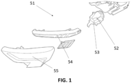
- Figure 1 shows an automotive luminous device 51 according to the state of the art.
- This automotive luminous device comprises a LED group 52, a reflector 53, a bezel 54 and an outer lens 55.
- the LED group emits light in a white colour, which is suitable for contributing to the passing beam lamp function.
- the reflector 53, the bezel 54 and the outer lens 55 due to the interposition of the reflector 53, the bezel 54 and the outer lens 55, the diffraction and reflection effects cause that the light which is finally projected outside the luminous device 51 does not comply with the national regulations.
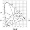
- Figure 2 shows a CIE 1931 chromaticity diagram, which is used in some countries to determine valid ranges for colours in different lighting and signalling functions. This diagram uses x and y coordinates, so that each particular colour is defined by these two coordinates.
- the "white colour”, as defined in some national regulations for passing beam lamp, is defined by a zone 20 delimited by the following segments:
- the colour emitted by the LED group of the previous figure is marked with a first point 56 in this diagram. This colour is comprised within the acceptable zone 20. However, due to the effect of the interposition of the different optical elements, the real colour which is projected by the headlamp of Figure 1 is marked with a second point 57, which is outside the acceptable zone 20.
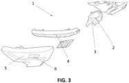
- a lighting device 1 according to the invention is presented in Figure 3 .
- This automotive luminous device also comprises a LED group 2, a reflector 3, a bezel 4 and an outer lens 5.
- the LED group 2 comprises a plurality of LEDs, each LED having a solid-state substrate, which emits in a blue wavelength, and a yellow phosphor, configured to add a different wavelength to the light emitted by the solid-state substrate, so that the light emitted by the LED is white.
- another type of LED such as a RGB LED, with a blue substrate, a green substrate and a red substrate, may be used instead of the classic blue+phosphor LED.
- the LED group 2 emits light in a white colour, which is comprised within the acceptable range of Figure 2 .
- the bezel 4 and the outer lens 5 due to the interposition of the reflector 3, the bezel 4 and the outer lens 5, the diffraction and reflection effects cause that the light which would be finally projected outside the luminous device 1 would not comply with the national regulations.
- the luminous device of this Figure 3 comprises the same LED group and the same optical elements of the device of Figure 1 , the light emitted by the device of Figure 3 (without the quantum dot layer that will be presented below) would correspond to the second point 57 of Figure 2 .
- the difference of the present invention compared with the headlamp shown in Figure 1 is the deposition of a quantum dot layer 6 on a region of the outer lens.
- This quantum dot layer 6 comprises a plurality of quantum dots which are configured to be excited by blue light emitted by the solid-state substrate of the LEDs. These quantum dots are carefully chosen to add a different wavelength to the one provided by the LED group, so that the light which is finally projected outside the lighting device (which would be the sum of the light emitted by the solid-state substrate, the correction of the phosphor, the effects of the optical parts and the correction of the quantum dot layer) corresponds to a value within the acceptable range 20 of Figure 2 .
- the method of the present invention therefore comprises
Landscapes
- Engineering & Computer Science (AREA)
- General Engineering & Computer Science (AREA)
- Physics & Mathematics (AREA)
- Microelectronics & Electronic Packaging (AREA)
- Optics & Photonics (AREA)
- Non-Portable Lighting Devices Or Systems Thereof (AREA)
Abstract
Description
- This invention belongs to the field of electronic assemblies comprised within the automotive luminous devices, intended to provide luminous functions to the vehicles.
- Automotive lighting market can be considered one of the most competitive ones and new lighting functionalities are constantly required.
- Colour is a very important feature of a beam which is projected by a lighting device. National regulations are often very strict about the particular features of beam colours.
- Each functionality in each country has a particular colour range which must be fit. LEDs are usually very carefully tested and chosen to fit this regulation colours.
- However, some optical parts of current headlamps (lens, reflectors, bezels...) may sometimes generate a shift in the colour of the LED, thus causing a final projected beam which do not comply with the original intention of the designer.
- This effect is difficult to predict, because until all the parts are assembled, the combined effects of them do not show.
- The present invention provides an automotive luminous device which is able to solve this problem.
- The invention provides an alternative solution for providing a light beam which complies with the colour regulations by an automotive luminous device. This automotive luminous device is intended to provide a lighting function, wherein the lighting function involves the projection of a light beam with a colour comprised in a predetermined colour range. The automotive luminous device comprises
- a light source comprising a first solid-state substrate and an additional element, the light source being configured to project a light beam with a colour different from the one of the light emitted by the first solid-state substrate, wherein the colour of the light projected by the light source is comprised in the predetermined colour range
- at least one primary optical part configured to receive the light of the light source and to project it outside the luminous device, so that the light projected by the at least one primary optical part has a colour not comprised within the predetermined colour range
- a wavelength conversion layer arranged to modify the colour of the light projected by the at least one primary optical part so that the final beam projected by the luminous device has a colour comprised in the predetermined colour range.
- The term "solid state" refers to light emitted by solid-state electroluminescence, which uses semiconductors to convert electricity into light. Compared to incandescent lighting, solid state lighting creates visible light with reduced heat generation and less energy dissipation. The typically small mass of a solid-state electronic lighting device provides for greater resistance to shock and vibration compared to brittle glass tubes/bulbs and long, thin filament wires. They also eliminate filament evaporation, potentially increasing the lifespan of the illumination device. Some examples of these types of lighting comprise semiconductor light-emitting diodes (LEDs), organic light-emitting diodes (OLED), or polymer light-emitting diodes (PLED) as sources of illumination rather than electrical filaments, plasma or gas.
- An optical part is an element that has some optical properties to receive a light beam and emit it in a certain direction and/or shape, as a person skilled in automotive lighting would construe without any additional burden. Reflectors, collimators, light guides, projection lenses, etc., or the combination thereof are some examples of these optical elements which are useful for transforming the light beams emitted by the light source into an acceptable light pattern for the functionality chosen for the lighting device. All of these optical elements define a focus, which is the point where the light emitted by the light source is most effectively transmitted by the optical element.
- The wavelength conversion layers are only in charge of providing the suitable colour for the lighting functionality, but do not provide the luminous flux necessary to fulfil the regulations. The light power is provided by the light sources, not by the wavelength conversion layer. However, the wavelength conversion layer may introduce some power losses when converting the light to a different wavelength, depending on the nature of the chosen layer.
- With this arrangement, the light which is finally emitted by the luminous device is comprised within the colour range defined by the corresponding regulations. Depending on each country and for each lighting function, a colour range is defined and, despite the light emitted by the light source may be within the acceptable range, when this light is altered by the optical parts, the colour of the whole lighting device may be outside this acceptable range. The wavelength conversion layer is deposited to correct the final colour and putting it back into the acceptable range.
- In some particular embodiments, the solid-state substrate is configured to emit light in a blue, deep blue or ultraviolet wavelength.
- These are the colours which are more commonly used in automotive functions, due to their luminous power.
- In some particular embodiments, the additional element is a phosphor, which is arranged on the first solid-state substrate.
- In the case of a white light source, a blue solid-state substrate and a yellow phosphor is a solution which is currently employed. The present invention finds a particular synergy with this type of light sources.
- In some particular embodiments, the additional element is a second solid-state substrate configured to emit in a red wavelength and third solid-state substrate configured to emit in a green wavelength.
- A different embodiment, but also compatible with the present invention is the use of a RBG LED, with three solid-state substrates, which are used to provide a suitable colour.
- In some particular embodiments, the predetermined colour range is defined in the CIE 1931 chromaticity diagram by the following segments
- x = 0.31, y ∈ (0.283, 0.348)
- x ∈ (0.31, 0.453), y = 0.15 + 0.64.x
- x ∈ (0.453, 0.5), y = 0.44
- x = 0.5, y ∈ (0.382, 0.44)
- x ∈ (0.443, 0.5), y = 0.382
- x ∈ (0.31, 0.443), y = 0.05 + 0.75·x
- This region corresponds to white colour, which is required by many lighting and signalling functions.
- In some particular embodiments, the wavelength conversion layer comprises quantum dots.
- A quantum dot is an electronic structure obtained out of a semiconductor nanocrystal, with a size such that their electrons and holes are confined in all three spatial dimensions. Depending on the particular sizes of the quantum dots, they emit light in a particular wavelength (bandgap) when they are excited, either electrically or luminescently. As a consequence, "red" quantum dots would be quantum dots which emit light in the red bandgap when excited, "green" quantum dots would be quantum dots which emit light in the green bandgap when excited, etc. However, when they are not excited, they may not be visible. This is because quantum dots are deposited in a nanometric layer using a thin film deposition technology. By controlling the amount and density of the quantum dots, this layer could be not visible when not excited either by an electric or by a luminescent stimulator.
- These quantum dots are an advantageous solution since they provide flexibility in the design of the automotive lighting devices, which in this case is required because the car manufacturer does not know to which direction is the final colour biased, so a dynamic and customized response is required for each situation.
- In some particular embodiments, the quantum dots are deposited on a substrate layer.
- This substrate layer may be deposited in the interior or exterior of the optical element, to modify the colour that each portion of this lightguide projects to the exterior.
- In some particular embodiments, the quantum dots are configured to be excited by blue light.
- Blue light is preferred due to its high energy peak, since the quantum dots are excited by any light which has an energy level equal or higher than the bandgap of the quantum dots.
- In some particular embodiments, the automotive luminous device further comprises a transparent plastic cover and wherein the wavelength conversion layer is deposited on the transparent plastic cover.
- The wavelength conversion layer may be deposited in any location between the light source and the exterior of the lighting device. However, the deposition in the transparent plastic cover is advantageous, since it may be done with a slight intervention on the already assembled device.
- In some particular embodiments, the light source is intended to contribute to a driving beam headlamp, a passing beam headlamp, a daytime running lamp, a position lamp or an interior lighting lamp.
- These lighting functions usually employ a white light, which is very sensitive to the modifications caused by the optical parts. For this reason, the invention is especially useful for these lighting functions.
- In some particular embodiments, the primary optical parts comprise at least one of a reflector, a diffusor, a collimator, a lens or a bezel.
- These optical parts are usually employed in headlamps. The aim of each part may be a mixture of optical and aesthetical, but in any case, they may affect to the colour of the beam which is projected outside the headlamp.
- In a further inventive aspect, the invention provides a method for manufacturing an automotive lighting device according to the first inventive aspect, the method comprising the steps of
- providing a light source comprising a solid-state substrate and an additional element, the light source being configured to project a light beam with a colour comprised in the predetermined colour range;
- providing at least one primary optical part arranged to receive the light of the light source and to project it outside the luminous device,
- checking the colour of the light projected by the at least one primary optical part choosing and assembling a wavelength conversion layer arranged to modify the colour of the light projected by the at least one primary optical part so that the final beam projected by the luminous device has a colour comprised in the predetermined colour range.
- With such a method, there is no need to disassemble the lighting device to change the BIN of the LED which is distorted by the optical elements. With a single operation of a deposition, the colour may be corrected so that the lighting device may operate without any major problem.
- Unless otherwise defined, all terms (including technical and scientific terms) used herein are to be interpreted as is customary in the art. It will be further understood that terms in common usage should also be interpreted as is customary in the relevant art and not in an idealised or overly formal sense unless expressly so defined herein.
- In this text, the term "comprises" and its derivations (such as "comprising", etc.) should not be understood in an excluding sense, that is, these terms should not be interpreted as excluding the possibility that what is described and defined may include further elements, steps, etc.
- To complete the description and in order to provide for a better understanding of the invention, a set of drawings is provided. Said drawings form an integral part of the description and illustrate an embodiment of the invention, which should not be interpreted as restricting the scope of the invention, but just as an example of how the invention can be carried out. The drawings comprise the following figures:
-
Figure 1 shows an automotive luminous device according to the state of the art. -
Figure 2 shows a CIE 1931 chromaticity diagram, which is used in some countries to determine valid ranges for colours in different lighting and signalling functions. -
Figure 3 shows an automotive luminous device according to one embodiment of the present invention. - In these figures, the following reference numbers have been used:
- 1
- Headlamp
- 2
- LED group
- 3
- Reflector
- 4
- Bezel
- 5
- Outer lens
- 6
- Quantum dot layer
- 20
- Acceptable zone of the chromaticity diagram for white colour
- 51
- Headlamp of the state of the art
- 52
- LED group in the headlamp of the state of the art
- 53
- Reflector in the headlamp of the state of the art
- 54
- Bezel in the headlamp of the state of the art
- 55
- Outer lens in the headlamp of the state of the art
- 56
- First point
- 57
- Second point
- The example embodiments are described in sufficient detail to enable those of ordinary skill in the art to embody and implement the systems and processes herein described. It is important to understand that embodiments can be provided in many alternate forms and should not be construed as limited to the examples set forth herein.
- Accordingly, while embodiment can be modified in various ways and take on various alternative forms, specific embodiments thereof are shown in the drawings and described in detail below as examples. There is no intent to limit to the particular forms disclosed. On the contrary, all modifications, equivalents, and alternatives falling within the scope of the appended claims should be included. Elements of the example embodiments are consistently denoted by the same reference numerals throughout the drawings and detailed description where appropriate.
-
Figure 1 shows an automotiveluminous device 51 according to the state of the art. - This automotive luminous device comprises a
LED group 52, areflector 53, abezel 54 and anouter lens 55. - The LED group emits light in a white colour, which is suitable for contributing to the passing beam lamp function. However, due to the interposition of the
reflector 53, thebezel 54 and theouter lens 55, the diffraction and reflection effects cause that the light which is finally projected outside theluminous device 51 does not comply with the national regulations. -
Figure 2 shows a CIE 1931 chromaticity diagram, which is used in some countries to determine valid ranges for colours in different lighting and signalling functions. This diagram uses x and y coordinates, so that each particular colour is defined by these two coordinates. - In this diagram, for example, the "white colour", as defined in some national regulations for passing beam lamp, is defined by a
zone 20 delimited by the following segments: - x = 0.31, y ∈ (0.283, 0.348)
- x ∈ (0.31, 0.453), y = 0.15 + 0.64·x
- x ∈ (0.453, 0.5), y = 0.44
- x = 0.5, y ∈ (0.382, 0.44)
- x ∈ (0.443, 0.5), y = 0.382
- x ∈ (0.31, 0.443), y = 0.05 + 0.75·x
- Any particular tone of white within this region would be acceptable as "white colour" to comply with the regulations in some countries.
- The colour emitted by the LED group of the previous figure is marked with a
first point 56 in this diagram. This colour is comprised within theacceptable zone 20. However, due to the effect of the interposition of the different optical elements, the real colour which is projected by the headlamp ofFigure 1 is marked with asecond point 57, which is outside theacceptable zone 20. - This would cause problems in the homologation of the headlamp of
Figure 1 . - To solve this problem, a
lighting device 1 according to the invention is presented inFigure 3 . - This automotive luminous device also comprises a
LED group 2, areflector 3, abezel 4 and anouter lens 5. - The
LED group 2 comprises a plurality of LEDs, each LED having a solid-state substrate, which emits in a blue wavelength, and a yellow phosphor, configured to add a different wavelength to the light emitted by the solid-state substrate, so that the light emitted by the LED is white. - In different embodiments, another type of LED, such as a RGB LED, with a blue substrate, a green substrate and a red substrate, may be used instead of the classic blue+phosphor LED.
- Hence, the
LED group 2 emits light in a white colour, which is comprised within the acceptable range ofFigure 2 . However, due to the interposition of thereflector 3, thebezel 4 and theouter lens 5, the diffraction and reflection effects cause that the light which would be finally projected outside theluminous device 1 would not comply with the national regulations. Since in this example, the luminous device of thisFigure 3 comprises the same LED group and the same optical elements of the device ofFigure 1 , the light emitted by the device ofFigure 3 (without the quantum dot layer that will be presented below) would correspond to thesecond point 57 ofFigure 2 . - To solve this problem, the difference of the present invention compared with the headlamp shown in
Figure 1 is the deposition of aquantum dot layer 6 on a region of the outer lens. - This
quantum dot layer 6 comprises a plurality of quantum dots which are configured to be excited by blue light emitted by the solid-state substrate of the LEDs. These quantum dots are carefully chosen to add a different wavelength to the one provided by the LED group, so that the light which is finally projected outside the lighting device (which would be the sum of the light emitted by the solid-state substrate, the correction of the phosphor, the effects of the optical parts and the correction of the quantum dot layer) corresponds to a value within theacceptable range 20 ofFigure 2 . - The method of the present invention therefore comprises
- providing a lighting device which, despite having a LED group which emits light in an acceptable colour, would not be homologated, due to the distortion effect caused by the optical parts
- check the preliminary colour of the light emitted by this device
- define an ad-hoc quantum dot layer as a function of this preliminary colour
- installing the quantum dot layer in the lighting device, in the light path of the light emitted by the LED group and projected by the optical elements.
- With this method, a successful correction is achieved without a major disassemble of the lighting device.
Claims (12)
- Automotive luminous device (1) being intended to provide a lighting function, wherein the lighting function involves the projection of a light beam with a colour comprised in a predetermined colour range (20), the automotive luminous device (1) comprisinga light source (2) comprising a first solid-state substrate and an additional element, the light source being configured to project a light beam with a colour different from the one of the light emitted by the first solid-state substrate, wherein the colour of the light projected by the light source is comprised in the predetermined colour range (20)at least one primary optical part (3, 4, 5) configured to receive the light of the light source (2) and to project it outside the luminous device (1), so that the light projected by the at least one primary optical part has a colour not comprised within the predetermined colour rangea wavelength conversion layer (6) arranged to modify the colour of the light projected by the at least one primary optical part (3, 4, 5) so that the final beam projected by the luminous device has a colour comprised in the predetermined colour range.
- Automotive luminous device according to claim 1, wherein the first solid-state substrate is configured to emit light in a blue, deep blue or ultraviolet wavelength.
- Automotive luminous device according to claim 2, wherein the additional element is a phosphor, which is arranged on the first solid-state substrate.
- Automotive luminous device according to claim 2, wherein the additional element is a second solid-state substrate configured to emit in a red wavelength and third solid-state substrate configured to emit in a green wavelength.
- Automotive luminous device according to any of the preceding claims, wherein the predetermined colour range (20) is defined in the CIE 1931 chromaticity diagram by the following segmentsx = 0.31, y ∈ (0.283, 0.348)x ∈ (0.31, 0.453), y = 0.15 + 0.64·xx ∈ (0.453, 0.5), y = 0.44x = 0.5, y ∈ (0.382, 0.44)x ∈ (0.443, 0.5), y = 0.382x ∈ (0.31, 0.443), y = 0.05 + 0.75·x
- Automotive luminous device according to any of the preceding claims, wherein the wavelength conversion layer (6) comprises quantum dots.
- Automotive luminous device according to claim 6, wherein the quantum dots are deposited on a substrate layer.
- Automotive luminous device according to any of claims 6 or 7, wherein the quantum dots are configured to be excited by blue light.
- Automotive luminous device according to any of the preceding claims, further comprising a transparent plastic cover and wherein the wavelength conversion layer is deposited on the transparent plastic cover.
- Automotive luminous device according to any of the preceding claims, wherein the light source is intended to contribute to a driving beam headlamp, a passing beam headlamp, a daytime running lamp, a position lamp or interior lighting lamps.
- Automotive luminous device according to any of the preceding claims, wherein the primary optical parts comprise at least one of a reflector, a diffusor, a collimator, a lens or a bezel.
- Method for manufacturing an automotive lighting device according to any of the preceding claims, the method comprising the steps ofproviding a light source (2) comprising a solid-state substrate and an additional element, the light source being configured to project a light beam with a colour comprised in the predetermined colour range (20);providing at least one primary optical part (3, 4, 5) arranged to receive the light of the light source and to project it outside the luminous device,checking the colour of the light projected by the at least one primary optical partchoosing and assembling a wavelength conversion layer arranged to modify the colour of the light projected by the at least one primary optical part so that the final beam projected by the luminous device has a colour comprised in the predetermined colour range (20).
Priority Applications (2)
| Application Number | Priority Date | Filing Date | Title |
|---|---|---|---|
| EP22165633.3A EP4253828B1 (en) | 2022-03-30 | 2022-03-30 | Automotive luminous device |
| PCT/EP2023/057537 WO2023186710A1 (en) | 2022-03-30 | 2023-03-23 | Automotive luminous device |
Applications Claiming Priority (1)
| Application Number | Priority Date | Filing Date | Title |
|---|---|---|---|
| EP22165633.3A EP4253828B1 (en) | 2022-03-30 | 2022-03-30 | Automotive luminous device |
Publications (2)
| Publication Number | Publication Date |
|---|---|
| EP4253828A1 true EP4253828A1 (en) | 2023-10-04 |
| EP4253828B1 EP4253828B1 (en) | 2025-06-04 |
Family
ID=81327956
Family Applications (1)
| Application Number | Title | Priority Date | Filing Date |
|---|---|---|---|
| EP22165633.3A Active EP4253828B1 (en) | 2022-03-30 | 2022-03-30 | Automotive luminous device |
Country Status (2)
| Country | Link |
|---|---|
| EP (1) | EP4253828B1 (en) |
| WO (1) | WO2023186710A1 (en) |
Cited By (1)
| Publication number | Priority date | Publication date | Assignee | Title |
|---|---|---|---|---|
| US12498095B2 (en) | 2023-08-23 | 2025-12-16 | Autosystems, A Division Of Magna Exteriors Inc. | Vehicle lighting assembly with three-dimensional luminescent structure |
Citations (6)
| Publication number | Priority date | Publication date | Assignee | Title |
|---|---|---|---|---|
| EP1671059A1 (en) * | 2003-10-03 | 2006-06-21 | General Electric Company | Automotive headlamps with improved beam chromaticity |
| US20130120688A1 (en) * | 2011-11-14 | 2013-05-16 | Planck Co., Ltd. | Color regulating device for illumination and apparatus using the same, and method of regulating color |
| DE102013205836A1 (en) * | 2013-04-03 | 2014-10-09 | Osram Opto Semiconductors Gmbh | vehicle light |
| DE102014203245A1 (en) * | 2014-02-24 | 2015-08-27 | Automotive Lighting Reutlingen Gmbh | Lighting device of a motor vehicle |
| EP3546821A1 (en) * | 2018-03-29 | 2019-10-02 | Valeo Iluminacion | Lighting device |
| WO2020157060A1 (en) * | 2019-01-31 | 2020-08-06 | Bayerische Motoren Werke Aktiengesellschaft | Illumination apparatus for a motor vehicle |
Family Cites Families (1)
| Publication number | Priority date | Publication date | Assignee | Title |
|---|---|---|---|---|
| JP2015032439A (en) * | 2013-08-02 | 2015-02-16 | スタンレー電気株式会社 | Vehicle headlight |
-
2022
- 2022-03-30 EP EP22165633.3A patent/EP4253828B1/en active Active
-
2023
- 2023-03-23 WO PCT/EP2023/057537 patent/WO2023186710A1/en not_active Ceased
Patent Citations (6)
| Publication number | Priority date | Publication date | Assignee | Title |
|---|---|---|---|---|
| EP1671059A1 (en) * | 2003-10-03 | 2006-06-21 | General Electric Company | Automotive headlamps with improved beam chromaticity |
| US20130120688A1 (en) * | 2011-11-14 | 2013-05-16 | Planck Co., Ltd. | Color regulating device for illumination and apparatus using the same, and method of regulating color |
| DE102013205836A1 (en) * | 2013-04-03 | 2014-10-09 | Osram Opto Semiconductors Gmbh | vehicle light |
| DE102014203245A1 (en) * | 2014-02-24 | 2015-08-27 | Automotive Lighting Reutlingen Gmbh | Lighting device of a motor vehicle |
| EP3546821A1 (en) * | 2018-03-29 | 2019-10-02 | Valeo Iluminacion | Lighting device |
| WO2020157060A1 (en) * | 2019-01-31 | 2020-08-06 | Bayerische Motoren Werke Aktiengesellschaft | Illumination apparatus for a motor vehicle |
Cited By (1)
| Publication number | Priority date | Publication date | Assignee | Title |
|---|---|---|---|---|
| US12498095B2 (en) | 2023-08-23 | 2025-12-16 | Autosystems, A Division Of Magna Exteriors Inc. | Vehicle lighting assembly with three-dimensional luminescent structure |
Also Published As
| Publication number | Publication date |
|---|---|
| EP4253828B1 (en) | 2025-06-04 |
| WO2023186710A1 (en) | 2023-10-05 |
Similar Documents
| Publication | Publication Date | Title |
|---|---|---|
| US10119671B2 (en) | Light emitting device and vehicular lamp including the same | |
| CN101520139B (en) | Semiconductor light emitting device | |
| US20110176305A1 (en) | Radiation-emitting apparatus | |
| CN101147261A (en) | Lighting device | |
| US20140160728A1 (en) | Light emitting apparatus | |
| WO2011107904A1 (en) | Lighting device with lamp and oled | |
| JP2014154803A (en) | Led light-emitting device and vehicular lighting fixture employing the same | |
| US20120162985A1 (en) | Solid state lighting unit incorporating optical spreading elements | |
| EP4253828B1 (en) | Automotive luminous device | |
| WO2020002144A1 (en) | Led filament lamp | |
| US9103509B2 (en) | Lighting device and method for operating a lighting device | |
| US20130201669A1 (en) | Led illumination apparatus with improved output uniformity | |
| US20200003392A1 (en) | Light-emitting module | |
| EP4253830A1 (en) | Automotive luminous device | |
| JP2020004960A (en) | Light-emitting module | |
| US10690308B2 (en) | Automotive lighting device | |
| EP4253831A1 (en) | Automotive luminous device | |
| EP4253832A1 (en) | Automotive luminous arrangement | |
| US11178736B2 (en) | Electronic assembly, lighting device and method for manufacturing a lighting device | |
| EP4372269A1 (en) | Automotive luminous device | |
| EP4291820A1 (en) | Automotive luminous device | |
| CN220506558U (en) | Automotive LED lighting components and vehicle exterior LED lights containing the same | |
| US20190355876A1 (en) | Light emitting diode (led) package | |
| EP3546821A1 (en) | Lighting device | |
| EP4574569A1 (en) | Automotive luminous device |
Legal Events
| Date | Code | Title | Description |
|---|---|---|---|
| PUAI | Public reference made under article 153(3) epc to a published international application that has entered the european phase |
Free format text: ORIGINAL CODE: 0009012 |
|
| STAA | Information on the status of an ep patent application or granted ep patent |
Free format text: STATUS: THE APPLICATION HAS BEEN PUBLISHED |
|
| AK | Designated contracting states |
Kind code of ref document: A1 Designated state(s): AL AT BE BG CH CY CZ DE DK EE ES FI FR GB GR HR HU IE IS IT LI LT LU LV MC MK MT NL NO PL PT RO RS SE SI SK SM TR |
|
| STAA | Information on the status of an ep patent application or granted ep patent |
Free format text: STATUS: REQUEST FOR EXAMINATION WAS MADE |
|
| 17P | Request for examination filed |
Effective date: 20240402 |
|
| RBV | Designated contracting states (corrected) |
Designated state(s): AL AT BE BG CH CY CZ DE DK EE ES FI FR GB GR HR HU IE IS IT LI LT LU LV MC MK MT NL NO PL PT RO RS SE SI SK SM TR |
|
| STAA | Information on the status of an ep patent application or granted ep patent |
Free format text: STATUS: EXAMINATION IS IN PROGRESS |
|
| 17Q | First examination report despatched |
Effective date: 20240612 |
|
| GRAP | Despatch of communication of intention to grant a patent |
Free format text: ORIGINAL CODE: EPIDOSNIGR1 |
|
| STAA | Information on the status of an ep patent application or granted ep patent |
Free format text: STATUS: GRANT OF PATENT IS INTENDED |
|
| INTG | Intention to grant announced |
Effective date: 20250123 |
|
| GRAS | Grant fee paid |
Free format text: ORIGINAL CODE: EPIDOSNIGR3 |
|
| GRAA | (expected) grant |
Free format text: ORIGINAL CODE: 0009210 |
|
| STAA | Information on the status of an ep patent application or granted ep patent |
Free format text: STATUS: THE PATENT HAS BEEN GRANTED |
|
| AK | Designated contracting states |
Kind code of ref document: B1 Designated state(s): AL AT BE BG CH CY CZ DE DK EE ES FI FR GB GR HR HU IE IS IT LI LT LU LV MC MK MT NL NO PL PT RO RS SE SI SK SM TR |
|
| REG | Reference to a national code |
Ref country code: GB Ref legal event code: FG4D |
|
| REG | Reference to a national code |
Ref country code: CH Ref legal event code: EP |
|
| REG | Reference to a national code |
Ref country code: DE Ref legal event code: R096 Ref document number: 602022015341 Country of ref document: DE |
|
| REG | Reference to a national code |
Ref country code: IE Ref legal event code: FG4D |
|
| REG | Reference to a national code |
Ref country code: NL Ref legal event code: MP Effective date: 20250604 |
|
| PG25 | Lapsed in a contracting state [announced via postgrant information from national office to epo] |
Ref country code: ES Free format text: LAPSE BECAUSE OF FAILURE TO SUBMIT A TRANSLATION OF THE DESCRIPTION OR TO PAY THE FEE WITHIN THE PRESCRIBED TIME-LIMIT Effective date: 20250604 Ref country code: FI Free format text: LAPSE BECAUSE OF FAILURE TO SUBMIT A TRANSLATION OF THE DESCRIPTION OR TO PAY THE FEE WITHIN THE PRESCRIBED TIME-LIMIT Effective date: 20250604 |
|
| REG | Reference to a national code |
Ref country code: LT Ref legal event code: MG9D |
|
| PG25 | Lapsed in a contracting state [announced via postgrant information from national office to epo] |
Ref country code: GR Free format text: LAPSE BECAUSE OF FAILURE TO SUBMIT A TRANSLATION OF THE DESCRIPTION OR TO PAY THE FEE WITHIN THE PRESCRIBED TIME-LIMIT Effective date: 20250905 Ref country code: NO Free format text: LAPSE BECAUSE OF FAILURE TO SUBMIT A TRANSLATION OF THE DESCRIPTION OR TO PAY THE FEE WITHIN THE PRESCRIBED TIME-LIMIT Effective date: 20250904 |
|
| PG25 | Lapsed in a contracting state [announced via postgrant information from national office to epo] |
Ref country code: PL Free format text: LAPSE BECAUSE OF FAILURE TO SUBMIT A TRANSLATION OF THE DESCRIPTION OR TO PAY THE FEE WITHIN THE PRESCRIBED TIME-LIMIT Effective date: 20250604 |
|
| PG25 | Lapsed in a contracting state [announced via postgrant information from national office to epo] |
Ref country code: BG Free format text: LAPSE BECAUSE OF FAILURE TO SUBMIT A TRANSLATION OF THE DESCRIPTION OR TO PAY THE FEE WITHIN THE PRESCRIBED TIME-LIMIT Effective date: 20250604 |
|
| PG25 | Lapsed in a contracting state [announced via postgrant information from national office to epo] |
Ref country code: HR Free format text: LAPSE BECAUSE OF FAILURE TO SUBMIT A TRANSLATION OF THE DESCRIPTION OR TO PAY THE FEE WITHIN THE PRESCRIBED TIME-LIMIT Effective date: 20250604 |
|
| PG25 | Lapsed in a contracting state [announced via postgrant information from national office to epo] |
Ref country code: RS Free format text: LAPSE BECAUSE OF FAILURE TO SUBMIT A TRANSLATION OF THE DESCRIPTION OR TO PAY THE FEE WITHIN THE PRESCRIBED TIME-LIMIT Effective date: 20250904 |
|
| PG25 | Lapsed in a contracting state [announced via postgrant information from national office to epo] |
Ref country code: LV Free format text: LAPSE BECAUSE OF FAILURE TO SUBMIT A TRANSLATION OF THE DESCRIPTION OR TO PAY THE FEE WITHIN THE PRESCRIBED TIME-LIMIT Effective date: 20250604 |
|
| PG25 | Lapsed in a contracting state [announced via postgrant information from national office to epo] |
Ref country code: NL Free format text: LAPSE BECAUSE OF FAILURE TO SUBMIT A TRANSLATION OF THE DESCRIPTION OR TO PAY THE FEE WITHIN THE PRESCRIBED TIME-LIMIT Effective date: 20250604 |
|
| PG25 | Lapsed in a contracting state [announced via postgrant information from national office to epo] |
Ref country code: PT Free format text: LAPSE BECAUSE OF FAILURE TO SUBMIT A TRANSLATION OF THE DESCRIPTION OR TO PAY THE FEE WITHIN THE PRESCRIBED TIME-LIMIT Effective date: 20251006 |
|
| REG | Reference to a national code |
Ref country code: AT Ref legal event code: MK05 Ref document number: 1800630 Country of ref document: AT Kind code of ref document: T Effective date: 20250604 |
|
| PG25 | Lapsed in a contracting state [announced via postgrant information from national office to epo] |
Ref country code: IS Free format text: LAPSE BECAUSE OF FAILURE TO SUBMIT A TRANSLATION OF THE DESCRIPTION OR TO PAY THE FEE WITHIN THE PRESCRIBED TIME-LIMIT Effective date: 20251004 |
|
| PG25 | Lapsed in a contracting state [announced via postgrant information from national office to epo] |
Ref country code: SM Free format text: LAPSE BECAUSE OF FAILURE TO SUBMIT A TRANSLATION OF THE DESCRIPTION OR TO PAY THE FEE WITHIN THE PRESCRIBED TIME-LIMIT Effective date: 20250604 Ref country code: AT Free format text: LAPSE BECAUSE OF FAILURE TO SUBMIT A TRANSLATION OF THE DESCRIPTION OR TO PAY THE FEE WITHIN THE PRESCRIBED TIME-LIMIT Effective date: 20250604 |
|
| PG25 | Lapsed in a contracting state [announced via postgrant information from national office to epo] |
Ref country code: CZ Free format text: LAPSE BECAUSE OF FAILURE TO SUBMIT A TRANSLATION OF THE DESCRIPTION OR TO PAY THE FEE WITHIN THE PRESCRIBED TIME-LIMIT Effective date: 20250604 |
|
| PG25 | Lapsed in a contracting state [announced via postgrant information from national office to epo] |
Ref country code: EE Free format text: LAPSE BECAUSE OF FAILURE TO SUBMIT A TRANSLATION OF THE DESCRIPTION OR TO PAY THE FEE WITHIN THE PRESCRIBED TIME-LIMIT Effective date: 20250604 |
|
| PG25 | Lapsed in a contracting state [announced via postgrant information from national office to epo] |
Ref country code: SK Free format text: LAPSE BECAUSE OF FAILURE TO SUBMIT A TRANSLATION OF THE DESCRIPTION OR TO PAY THE FEE WITHIN THE PRESCRIBED TIME-LIMIT Effective date: 20250604 |
|
| PG25 | Lapsed in a contracting state [announced via postgrant information from national office to epo] |
Ref country code: IT Free format text: LAPSE BECAUSE OF FAILURE TO SUBMIT A TRANSLATION OF THE DESCRIPTION OR TO PAY THE FEE WITHIN THE PRESCRIBED TIME-LIMIT Effective date: 20250604 |
|
| REG | Reference to a national code |
Ref country code: DE Ref legal event code: R097 Ref document number: 602022015341 Country of ref document: DE |
|
| PLBE | No opposition filed within time limit |
Free format text: ORIGINAL CODE: 0009261 |
|
| STAA | Information on the status of an ep patent application or granted ep patent |
Free format text: STATUS: NO OPPOSITION FILED WITHIN TIME LIMIT |
|
| PG25 | Lapsed in a contracting state [announced via postgrant information from national office to epo] |
Ref country code: DK Free format text: LAPSE BECAUSE OF FAILURE TO SUBMIT A TRANSLATION OF THE DESCRIPTION OR TO PAY THE FEE WITHIN THE PRESCRIBED TIME-LIMIT Effective date: 20250604 |
|
| PGFP | Annual fee paid to national office [announced via postgrant information from national office to epo] |
Ref country code: DE Payment date: 20260313 Year of fee payment: 5 |
|
| REG | Reference to a national code |
Ref country code: CH Ref legal event code: L10 Free format text: ST27 STATUS EVENT CODE: U-0-0-L10-L00 (AS PROVIDED BY THE NATIONAL OFFICE) Effective date: 20260416 |
|
| PGFP | Annual fee paid to national office [announced via postgrant information from national office to epo] |
Ref country code: FR Payment date: 20260331 Year of fee payment: 5 |
|
| 26N | No opposition filed |
Effective date: 20260305 |