EP4253777B1 - Gleitlager mit öltasche - Google Patents
Gleitlager mit öltasche Download PDFInfo
- Publication number
- EP4253777B1 EP4253777B1 EP23164836.1A EP23164836A EP4253777B1 EP 4253777 B1 EP4253777 B1 EP 4253777B1 EP 23164836 A EP23164836 A EP 23164836A EP 4253777 B1 EP4253777 B1 EP 4253777B1
- Authority
- EP
- European Patent Office
- Prior art keywords
- journal
- shaft
- journal shaft
- pin
- oil pocket
- Prior art date
- Legal status (The legal status is an assumption and is not a legal conclusion. Google has not performed a legal analysis and makes no representation as to the accuracy of the status listed.)
- Active
Links
Images



Classifications
-
- F—MECHANICAL ENGINEERING; LIGHTING; HEATING; WEAPONS; BLASTING
- F16—ENGINEERING ELEMENTS AND UNITS; GENERAL MEASURES FOR PRODUCING AND MAINTAINING EFFECTIVE FUNCTIONING OF MACHINES OR INSTALLATIONS; THERMAL INSULATION IN GENERAL
- F16C—SHAFTS; FLEXIBLE SHAFTS; ELEMENTS OR CRANKSHAFT MECHANISMS; ROTARY BODIES OTHER THAN GEARING ELEMENTS; BEARINGS
- F16C32/00—Bearings not otherwise provided for
- F16C32/06—Bearings not otherwise provided for with moving member supported by a fluid cushion formed, at least to a large extent, otherwise than by movement of the shaft, e.g. hydrostatic air-cushion bearings
- F16C32/0629—Bearings not otherwise provided for with moving member supported by a fluid cushion formed, at least to a large extent, otherwise than by movement of the shaft, e.g. hydrostatic air-cushion bearings supported by a liquid cushion, e.g. oil cushion
- F16C32/064—Bearings not otherwise provided for with moving member supported by a fluid cushion formed, at least to a large extent, otherwise than by movement of the shaft, e.g. hydrostatic air-cushion bearings supported by a liquid cushion, e.g. oil cushion the liquid being supplied under pressure
- F16C32/0651—Details of the bearing area per se
- F16C32/0659—Details of the bearing area per se of pockets or grooves
-
- F—MECHANICAL ENGINEERING; LIGHTING; HEATING; WEAPONS; BLASTING
- F01—MACHINES OR ENGINES IN GENERAL; ENGINE PLANTS IN GENERAL; STEAM ENGINES
- F01D—NON-POSITIVE DISPLACEMENT MACHINES OR ENGINES, e.g. STEAM TURBINES
- F01D25/00—Component parts, details, or accessories, not provided for in, or of interest apart from, other groups
- F01D25/16—Arrangement of bearings; Supporting or mounting bearings in casings
- F01D25/162—Bearing supports
-
- F—MECHANICAL ENGINEERING; LIGHTING; HEATING; WEAPONS; BLASTING
- F01—MACHINES OR ENGINES IN GENERAL; ENGINE PLANTS IN GENERAL; STEAM ENGINES
- F01D—NON-POSITIVE DISPLACEMENT MACHINES OR ENGINES, e.g. STEAM TURBINES
- F01D25/00—Component parts, details, or accessories, not provided for in, or of interest apart from, other groups
- F01D25/18—Lubricating arrangements
-
- F—MECHANICAL ENGINEERING; LIGHTING; HEATING; WEAPONS; BLASTING
- F02—COMBUSTION ENGINES; HOT-GAS OR COMBUSTION-PRODUCT ENGINE PLANTS
- F02B—INTERNAL-COMBUSTION PISTON ENGINES; COMBUSTION ENGINES IN GENERAL
- F02B39/00—Component parts, details, or accessories relating to, driven charging or scavenging pumps, not provided for in groups F02B33/00 - F02B37/00
- F02B39/14—Lubrication of pumps; Safety measures therefor
-
- F—MECHANICAL ENGINEERING; LIGHTING; HEATING; WEAPONS; BLASTING
- F02—COMBUSTION ENGINES; HOT-GAS OR COMBUSTION-PRODUCT ENGINE PLANTS
- F02C—GAS-TURBINE PLANTS; AIR INTAKES FOR JET-PROPULSION PLANTS; CONTROLLING FUEL SUPPLY IN AIR-BREATHING JET-PROPULSION PLANTS
- F02C6/00—Plural gas-turbine plants; Combinations of gas-turbine plants with other apparatus; Adaptations of gas-turbine plants for special use
- F02C6/04—Gas-turbine plants providing heated or pressurised working fluid for other apparatus, e.g. without mechanical power output
- F02C6/10—Gas-turbine plants providing heated or pressurised working fluid for other apparatus, e.g. without mechanical power output supplying working fluid to a user, e.g. a chemical process, which returns working fluid to a turbine of the plant
- F02C6/12—Turbochargers, i.e. plants for augmenting mechanical power output of internal-combustion piston engines by increase of charge pressure
-
- F—MECHANICAL ENGINEERING; LIGHTING; HEATING; WEAPONS; BLASTING
- F04—POSITIVE - DISPLACEMENT MACHINES FOR LIQUIDS; PUMPS FOR LIQUIDS OR ELASTIC FLUIDS
- F04D—NON-POSITIVE-DISPLACEMENT PUMPS
- F04D29/00—Details, component parts, or accessories
- F04D29/04—Shafts or bearings, or assemblies thereof
- F04D29/046—Bearings
-
- F—MECHANICAL ENGINEERING; LIGHTING; HEATING; WEAPONS; BLASTING
- F16—ENGINEERING ELEMENTS AND UNITS; GENERAL MEASURES FOR PRODUCING AND MAINTAINING EFFECTIVE FUNCTIONING OF MACHINES OR INSTALLATIONS; THERMAL INSULATION IN GENERAL
- F16C—SHAFTS; FLEXIBLE SHAFTS; ELEMENTS OR CRANKSHAFT MECHANISMS; ROTARY BODIES OTHER THAN GEARING ELEMENTS; BEARINGS
- F16C17/00—Sliding-contact bearings for exclusively rotary movement
- F16C17/02—Sliding-contact bearings for exclusively rotary movement for radial load only
-
- F—MECHANICAL ENGINEERING; LIGHTING; HEATING; WEAPONS; BLASTING
- F16—ENGINEERING ELEMENTS AND UNITS; GENERAL MEASURES FOR PRODUCING AND MAINTAINING EFFECTIVE FUNCTIONING OF MACHINES OR INSTALLATIONS; THERMAL INSULATION IN GENERAL
- F16C—SHAFTS; FLEXIBLE SHAFTS; ELEMENTS OR CRANKSHAFT MECHANISMS; ROTARY BODIES OTHER THAN GEARING ELEMENTS; BEARINGS
- F16C17/00—Sliding-contact bearings for exclusively rotary movement
- F16C17/12—Sliding-contact bearings for exclusively rotary movement characterised by features not related to the direction of the load
- F16C17/18—Sliding-contact bearings for exclusively rotary movement characterised by features not related to the direction of the load with floating brasses or brushing, rotatable at a reduced speed
-
- F—MECHANICAL ENGINEERING; LIGHTING; HEATING; WEAPONS; BLASTING
- F16—ENGINEERING ELEMENTS AND UNITS; GENERAL MEASURES FOR PRODUCING AND MAINTAINING EFFECTIVE FUNCTIONING OF MACHINES OR INSTALLATIONS; THERMAL INSULATION IN GENERAL
- F16C—SHAFTS; FLEXIBLE SHAFTS; ELEMENTS OR CRANKSHAFT MECHANISMS; ROTARY BODIES OTHER THAN GEARING ELEMENTS; BEARINGS
- F16C17/00—Sliding-contact bearings for exclusively rotary movement
- F16C17/12—Sliding-contact bearings for exclusively rotary movement characterised by features not related to the direction of the load
- F16C17/24—Sliding-contact bearings for exclusively rotary movement characterised by features not related to the direction of the load with devices affected by abnormal or undesired positions, e.g. for preventing overheating, for safety
-
- F—MECHANICAL ENGINEERING; LIGHTING; HEATING; WEAPONS; BLASTING
- F16—ENGINEERING ELEMENTS AND UNITS; GENERAL MEASURES FOR PRODUCING AND MAINTAINING EFFECTIVE FUNCTIONING OF MACHINES OR INSTALLATIONS; THERMAL INSULATION IN GENERAL
- F16C—SHAFTS; FLEXIBLE SHAFTS; ELEMENTS OR CRANKSHAFT MECHANISMS; ROTARY BODIES OTHER THAN GEARING ELEMENTS; BEARINGS
- F16C33/00—Parts of bearings; Special methods for making bearings or parts thereof
- F16C33/02—Parts of sliding-contact bearings
- F16C33/04—Brasses; Bushes; Linings
- F16C33/06—Sliding surface mainly made of metal
- F16C33/10—Construction relative to lubrication
- F16C33/1025—Construction relative to lubrication with liquid, e.g. oil, as lubricant
- F16C33/1045—Details of supply of the liquid to the bearing
- F16C33/1055—Details of supply of the liquid to the bearing from radial inside, e.g. via a passage through the shaft and/or inner sleeve
-
- F—MECHANICAL ENGINEERING; LIGHTING; HEATING; WEAPONS; BLASTING
- F16—ENGINEERING ELEMENTS AND UNITS; GENERAL MEASURES FOR PRODUCING AND MAINTAINING EFFECTIVE FUNCTIONING OF MACHINES OR INSTALLATIONS; THERMAL INSULATION IN GENERAL
- F16C—SHAFTS; FLEXIBLE SHAFTS; ELEMENTS OR CRANKSHAFT MECHANISMS; ROTARY BODIES OTHER THAN GEARING ELEMENTS; BEARINGS
- F16C33/00—Parts of bearings; Special methods for making bearings or parts thereof
- F16C33/02—Parts of sliding-contact bearings
- F16C33/04—Brasses; Bushes; Linings
- F16C33/06—Sliding surface mainly made of metal
- F16C33/10—Construction relative to lubrication
- F16C33/1025—Construction relative to lubrication with liquid, e.g. oil, as lubricant
- F16C33/106—Details of distribution or circulation inside the bearings, e.g. details of the bearing surfaces to affect flow or pressure of the liquid
- F16C33/107—Grooves for generating pressure
-
- F—MECHANICAL ENGINEERING; LIGHTING; HEATING; WEAPONS; BLASTING
- F16—ENGINEERING ELEMENTS AND UNITS; GENERAL MEASURES FOR PRODUCING AND MAINTAINING EFFECTIVE FUNCTIONING OF MACHINES OR INSTALLATIONS; THERMAL INSULATION IN GENERAL
- F16H—GEARING
- F16H57/00—General details of gearing
- F16H57/04—Features relating to lubrication or cooling or heating
- F16H57/042—Guidance of lubricant
- F16H57/043—Guidance of lubricant within rotary parts, e.g. axial channels or radial openings in shafts
-
- F—MECHANICAL ENGINEERING; LIGHTING; HEATING; WEAPONS; BLASTING
- F16—ENGINEERING ELEMENTS AND UNITS; GENERAL MEASURES FOR PRODUCING AND MAINTAINING EFFECTIVE FUNCTIONING OF MACHINES OR INSTALLATIONS; THERMAL INSULATION IN GENERAL
- F16H—GEARING
- F16H57/00—General details of gearing
- F16H57/04—Features relating to lubrication or cooling or heating
- F16H57/0467—Elements of gearings to be lubricated, cooled or heated
- F16H57/0479—Gears or bearings on planet carriers
-
- F—MECHANICAL ENGINEERING; LIGHTING; HEATING; WEAPONS; BLASTING
- F05—INDEXING SCHEMES RELATING TO ENGINES OR PUMPS IN VARIOUS SUBCLASSES OF CLASSES F01-F04
- F05D—INDEXING SCHEME FOR ASPECTS RELATING TO NON-POSITIVE-DISPLACEMENT MACHINES OR ENGINES, GAS-TURBINES OR JET-PROPULSION PLANTS
- F05D2220/00—Application
- F05D2220/40—Application in turbochargers
-
- F—MECHANICAL ENGINEERING; LIGHTING; HEATING; WEAPONS; BLASTING
- F05—INDEXING SCHEMES RELATING TO ENGINES OR PUMPS IN VARIOUS SUBCLASSES OF CLASSES F01-F04
- F05D—INDEXING SCHEME FOR ASPECTS RELATING TO NON-POSITIVE-DISPLACEMENT MACHINES OR ENGINES, GAS-TURBINES OR JET-PROPULSION PLANTS
- F05D2240/00—Components
- F05D2240/50—Bearings
-
- F—MECHANICAL ENGINEERING; LIGHTING; HEATING; WEAPONS; BLASTING
- F05—INDEXING SCHEMES RELATING TO ENGINES OR PUMPS IN VARIOUS SUBCLASSES OF CLASSES F01-F04
- F05D—INDEXING SCHEME FOR ASPECTS RELATING TO NON-POSITIVE-DISPLACEMENT MACHINES OR ENGINES, GAS-TURBINES OR JET-PROPULSION PLANTS
- F05D2260/00—Function
- F05D2260/98—Lubrication
-
- F—MECHANICAL ENGINEERING; LIGHTING; HEATING; WEAPONS; BLASTING
- F16—ENGINEERING ELEMENTS AND UNITS; GENERAL MEASURES FOR PRODUCING AND MAINTAINING EFFECTIVE FUNCTIONING OF MACHINES OR INSTALLATIONS; THERMAL INSULATION IN GENERAL
- F16C—SHAFTS; FLEXIBLE SHAFTS; ELEMENTS OR CRANKSHAFT MECHANISMS; ROTARY BODIES OTHER THAN GEARING ELEMENTS; BEARINGS
- F16C2240/00—Specified values or numerical ranges of parameters; Relations between them
- F16C2240/12—Force, load, stress, pressure
- F16C2240/22—Fluid pressure
-
- F—MECHANICAL ENGINEERING; LIGHTING; HEATING; WEAPONS; BLASTING
- F16—ENGINEERING ELEMENTS AND UNITS; GENERAL MEASURES FOR PRODUCING AND MAINTAINING EFFECTIVE FUNCTIONING OF MACHINES OR INSTALLATIONS; THERMAL INSULATION IN GENERAL
- F16C—SHAFTS; FLEXIBLE SHAFTS; ELEMENTS OR CRANKSHAFT MECHANISMS; ROTARY BODIES OTHER THAN GEARING ELEMENTS; BEARINGS
- F16C2240/00—Specified values or numerical ranges of parameters; Relations between them
- F16C2240/26—Speed, e.g. rotational speed
-
- F—MECHANICAL ENGINEERING; LIGHTING; HEATING; WEAPONS; BLASTING
- F16—ENGINEERING ELEMENTS AND UNITS; GENERAL MEASURES FOR PRODUCING AND MAINTAINING EFFECTIVE FUNCTIONING OF MACHINES OR INSTALLATIONS; THERMAL INSULATION IN GENERAL
- F16C—SHAFTS; FLEXIBLE SHAFTS; ELEMENTS OR CRANKSHAFT MECHANISMS; ROTARY BODIES OTHER THAN GEARING ELEMENTS; BEARINGS
- F16C2240/00—Specified values or numerical ranges of parameters; Relations between them
- F16C2240/30—Angles, e.g. inclinations
-
- F—MECHANICAL ENGINEERING; LIGHTING; HEATING; WEAPONS; BLASTING
- F16—ENGINEERING ELEMENTS AND UNITS; GENERAL MEASURES FOR PRODUCING AND MAINTAINING EFFECTIVE FUNCTIONING OF MACHINES OR INSTALLATIONS; THERMAL INSULATION IN GENERAL
- F16C—SHAFTS; FLEXIBLE SHAFTS; ELEMENTS OR CRANKSHAFT MECHANISMS; ROTARY BODIES OTHER THAN GEARING ELEMENTS; BEARINGS
- F16C2360/00—Engines or pumps
- F16C2360/23—Gas turbine engines
-
- F—MECHANICAL ENGINEERING; LIGHTING; HEATING; WEAPONS; BLASTING
- F16—ENGINEERING ELEMENTS AND UNITS; GENERAL MEASURES FOR PRODUCING AND MAINTAINING EFFECTIVE FUNCTIONING OF MACHINES OR INSTALLATIONS; THERMAL INSULATION IN GENERAL
- F16C—SHAFTS; FLEXIBLE SHAFTS; ELEMENTS OR CRANKSHAFT MECHANISMS; ROTARY BODIES OTHER THAN GEARING ELEMENTS; BEARINGS
- F16C2360/00—Engines or pumps
- F16C2360/23—Gas turbine engines
- F16C2360/24—Turbochargers
-
- F—MECHANICAL ENGINEERING; LIGHTING; HEATING; WEAPONS; BLASTING
- F16—ENGINEERING ELEMENTS AND UNITS; GENERAL MEASURES FOR PRODUCING AND MAINTAINING EFFECTIVE FUNCTIONING OF MACHINES OR INSTALLATIONS; THERMAL INSULATION IN GENERAL
- F16C—SHAFTS; FLEXIBLE SHAFTS; ELEMENTS OR CRANKSHAFT MECHANISMS; ROTARY BODIES OTHER THAN GEARING ELEMENTS; BEARINGS
- F16C2361/00—Apparatus or articles in engineering in general
- F16C2361/61—Toothed gear systems, e.g. support of pinion shafts
-
- F—MECHANICAL ENGINEERING; LIGHTING; HEATING; WEAPONS; BLASTING
- F16—ENGINEERING ELEMENTS AND UNITS; GENERAL MEASURES FOR PRODUCING AND MAINTAINING EFFECTIVE FUNCTIONING OF MACHINES OR INSTALLATIONS; THERMAL INSULATION IN GENERAL
- F16C—SHAFTS; FLEXIBLE SHAFTS; ELEMENTS OR CRANKSHAFT MECHANISMS; ROTARY BODIES OTHER THAN GEARING ELEMENTS; BEARINGS
- F16C32/00—Bearings not otherwise provided for
- F16C32/06—Bearings not otherwise provided for with moving member supported by a fluid cushion formed, at least to a large extent, otherwise than by movement of the shaft, e.g. hydrostatic air-cushion bearings
- F16C32/0681—Construction or mounting aspects of hydrostatic bearings, for exclusively rotary movement, related to the direction of load
- F16C32/0685—Construction or mounting aspects of hydrostatic bearings, for exclusively rotary movement, related to the direction of load for radial load only
-
- F—MECHANICAL ENGINEERING; LIGHTING; HEATING; WEAPONS; BLASTING
- F16—ENGINEERING ELEMENTS AND UNITS; GENERAL MEASURES FOR PRODUCING AND MAINTAINING EFFECTIVE FUNCTIONING OF MACHINES OR INSTALLATIONS; THERMAL INSULATION IN GENERAL
- F16H—GEARING
- F16H57/00—General details of gearing
- F16H57/08—General details of gearing of gearings with members having orbital motion
- F16H2057/085—Bearings for orbital gears
Definitions
- the present invention relates generally to bearings for rotating shafts and/or assemblies in aircraft engines and, more particularly, to journal bearings for such aircraft engines.
- Aircraft engines typically include a number of rotating components or parts mounted together via mounting devices, such as bearings, providing suitable support and allowing rotational movement between the components.
- Roller bearings and/or journal bearings are often used for rotating shafts in such engines, including in their gearboxes.
- Journal bearings employ a journal shaft rotating in a sleeve.
- a fluid such as oil is used to create a film between the journal shaft and the gear sleeve. While suitable for their intended purposes, improvements of such journal bearings is sought.
- US 2020/347882 A1 relates to journal bearing assembly with dual oil cavities for gas turbine engines.
- US 8894529 B2 relates to journal pins in an epicyclic gear system.
- US 6056509 A relates to a contra-rotating bearing device for a contra-rotating propeller wherein a sufficient oil film is formed on the bearing surface of a contra-rotating bearing which supports the inner shaft of the contra-rotating propeller so that an excellent bearing function can be obtained.
- journal shaft for a journal bearing assembly of an aircraft engine as claimed in claim 1.
- journal bearing assembly for an aircraft engine as claimed in claim 11.
- FIG. 1 illustrates a gas turbine engine 10 of a type preferably provided for use in subsonic flight and configured for driving a load 12, such as, but not limited to, a propeller or a helicopter rotor or rotorcraft rotor.
- the engine 10 may be any suitable aircraft engine, and may be configured as a turboprop engine or a turboshaft engine.
- the gas turbine engine 10 generally comprises in serial flow communication a compressor section 14 for pressurizing the air, a combustor 16 in which the compressed air is mixed with fuel and ignited for generating an annular stream of hot combustion gases, and a turbine section 18 for extracting energy from the combustion gases. Also shown is a central longitudinal axis 11 of the engine 10.
- turboprop engine As an example, it is understood that aspects of the present disclosure may be equally applicable to other types of combustion engines in general, and other types of aircraft engines in particular, including but not limited to turboshaft or turbofan engines, hybrid-electric engines, auxiliary power units (APU), and the like.
- turboshaft or turbofan engines including but not limited to turboshaft or turbofan engines, hybrid-electric engines, auxiliary power units (APU), and the like.
- APU auxiliary power units
- the engine 10 also includes rotating parts or assemblies, such as gear assemblies 19 (e.g., epicycle reduction systems, planetary/reduction gearboxes (RGB), or other types of rotating assemblies) with rotating components mounted thereto using mounting devices allowing rotational and/or axial movement.
- gear assemblies 19 e.g., epicycle reduction systems, planetary/reduction gearboxes (RGB), or other types of rotating assemblies
- the gear assembly 19 is mounted at the front end of the engine 10, though it may be at other locations in the engine 10.
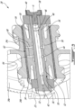
- An example of a gear assembly 19 as used in the engine 10 is shown in FIG. 2 .
- the gear assembly 19 is part of a reduction gearbox (RGB) of the engine 10.
- the RGB may include, for example, an epicycle reduction system, also known as epicyclic gear train, epicyclic gearbox, planetary gearbox, etc.
- an input torque through a sun shaft 20 is rotatably outputted through a sun gear 21 as an output torque through gear carriers 22 via a plurality of planet gears 24 rotatably connected to the gear carriers 22 and ring gears 26.
- the gear assembly 19 shown in FIG. 2 includes one or more mounting devices such as a journal bearing assembly 28.
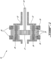
- the journal bearing assembly 28 includes a journal shaft 30 (also referred to as a journal or a shaft), an optional pin 32 (see FIG. 6 for an example of a pin-less journal bearing assembly), and, in this particular embodiment, a bearing sleeve 34.
- the bearing sleeve 34 may integrated directly into a surrounding component, such that the journal shaft 30 rotates within another bore, for example defined within the gear carrier or other suitable housing.
- the journal shaft 30 is thus rotatably mounted within a bore defined by a surrounding component, which component can be, for example, the sleeve 34, a gear, a carrier, another suitable shaft housing, etc.
- the journal bearing assembly 28 may be used for interfacing a rotating part to a structure.
- the rotating part is one or more gears such as planet gears 24 configured to rotate at speeds between 4,000 and 15,000 revolutions per minute (RPM), although other rotational speeds and arrangements are possible.
- the gear may be an epicycle gear of epicyclic reduction system, mounted on the journal bearing assembly 28 which is supported at both ends between two axially spaced supports forming at least part of the structure of the epicyclic gear system, the structure being for instance a carrier 22.
- the supports may be annular blocks (not shown) supporting the pin 32 at its opposed ends.
- the illustrated pin 32 is hollow with a pin inner cavity 36 and may be optionally closed at one end via a fastener such as a bolt 38 and a washer 40.
- a lubricating fluid film such as an oil film, may be received between rotating components of the journal bearing assembly 28 to facilitate rotation of said components relative to one another, as will be discussed in further detail below.
- the pin inner cavity 36 may thus include an inlet 42 and at least one outlet passage 44 for oil to flow through.
- pin outlet passages 44 are illustratively radially-extending pin outlet passages 44 (also referred to as “pin radial passages") that extend from a radially inner pin surface 46 that defines the pin inner cavity to a radially outer pin surface 48. While the illustrated pin 32 includes two such pin outlet passages 44, other numbers of outlet passages may be contemplated.
- the journal bearing assembly 28 may or may not include the sleeve 34 disposed radially outwardly to the journal shaft 30 relative to a longitudinal axis A of the journal bearing assembly 28.
- Such sleeve 34 may be used to form an outer peripheral surface of the journal bearing assembly 28, upon which the planet gears 24 are mounted in the illustrated embodiment. Otherwise, an outer surface of the journal shaft 30 may contact directly the rotating part it supports, e.g., the planet gears 24 in the illustrated embodiment, as will be discussed in further detail below.
- journal shaft 30 may be a monolithic piece. While journal shaft 30 is shown to be cylindrical, other shapes are possible such as frusto-conical, and the journal shaft 30 may have various surface features such as grooves, slots and channels, as will be discussed in further detail below.
- the journal shaft 30 includes a shaft body extending along the longitudinal axis A, which is the rotation axis of the rotating part, illustratively the three planet gears 24a, 24b, 24c.
- An inner cavity 50 or pin-receiving cavity 50 extends along the longitudinal axis A and defines a radially inner surface 52 of the journal shaft 30, also referred to as a pin-engaging surface 52 that engages the radially-outer pin surface 48. Stated differently, the radially inner surface 52 of the journal shaft 30 is radially spaced apart from the longitudinal axis A to define the inner cavity 50.
- the journal shaft 30 has a radially outer surface 54 that is configured for interfacing and supporting the rotating part, either directly (in a sleeveless embodiment) or via the optional sleeve 34.
- the pin-receiving cavity 50 may thus receive the pin 32 of the gear assembly 19 when mounted within such assembly 19.
- the shaft 30 may include various compliance features 56 at the distal ends of the journal shaft 30, which may also be referred to as undercuts or axial depressions.
- the journal bearing assembly 28 may have its journal shaft 30 fixed to the pin 32, such that the sleeve 34 (if present) or the rotating part (in a sleeveless embodiment) rotates about the pin 32 and the journal shaft 30. If present, the sleeve 34 concurrently rotates with the rotating part fixed thereon.
- the journal bearing assembly 28 may have its journal shaft 30 rotatably engaged with the rotating part it supports, such that the journal shaft 30 may be rotatable relative to the pin 32 and may have the rotating part mounted thereto rotatable relative to the journal shaft 30, for instance with the sleeve 34 fixed to the rotating part or to the journal shaft 30.
- a lubricating fluid such as oil may be provided through the pin inlet 42.
- the oil may flow through the pin inner cavity 36 towards the radially-extending pin outlet passages 44.
- Each pin outlet passage 44 extends from the radially inner pin surface 46 to the radially outer pin surface 48 which interfaces with the radially inner surface 52 of the journal shaft 30.
- the radially inner surface 52 includes at least one circumferential oil chamber 58 (illustratively two circumferential oil chambers 58) extending about the radially inner surface 52 and aligned with the pin outlet passages 44.
- the oil exiting from the pin outlet passages 44 may collect in respective circumferential oil chambers 58.
- At least one oil passage 60 extend radially through the journal shaft 30 with inlet sections 60a in fluid communication with respective circumferential oil chambers 58 and outlet sections 60b in fluid communication with an oil pocket 62 on the radially outer surface 54 of the journal shaft 30.
- oil passages 60 extend through the journal shaft 30 in a direction normal to the longitudinal axis A, although other directions may be contemplated. While two circumferential oil chambers 58 and two oil passages 60 are shown, the number of may vary and may be selected to match the number of pin outlet passages 44.
- the various passages 44, 60 and circumferential oil chambers 58 may be sized and shaped to control the flow of oil to the radially outer surface 54 of the journal shaft.
- the oil pocket 62 may hold oil (or another lubrication fluid) to be distributed between the radially-outer surface 54 of the journal shaft 30 and a radially-inner surface 64 of the sleeve 34.
- oil may enter the pin inner cavity 36 through oil inlet 42, pass through outlet passages 44 to circumferential oil chambers 58, then pass through oil passages 60 through journal shaft 30 to the oil pocket 62.
- the oil passages 60 may be configured for feeding oil to the oil pocket 62 at a pressure of about 100 PSI, although other pressures may be contemplated.
- the oil may then create a lubricating film between the radially-outer surface 54 of the journal shaft 30 and the radially-inner surface 64 of the sleeve 34 (or between the radially-outer surface 54 of the journal shaft 30 and the one or more gears 24 being supported in a sleeveless configuration).
- the oil pocket 62 includes a radially inner base surface 66, also referred to as a recessed base surface, that is illustratively concentric with the radially outer surface 54 of the journal shaft 30.
- the oil pocket 62 further includes interconnecting transition surfaces 68, illustratively a pair of interconnecting transition surfaces 68, extending between the radially inner base surface 66 of the oil pocket 62 and the radially outer surface 64 of the journal shaft 30.
- the pair of interconnecting transition surfaces 68 provide a fluid-dynamically smooth and edgeless transition between the radially inner base surface 66 and the radially outer surface 54 of the journal shaft 30.
- fluid-dynamically smooth and edgeless transition as used herein is understood to mean that the junction between the interconnecting transition surfaces 68 and the radially outer surface 54 does not include sharp or pointed edges.
- This smooth or seamless design provides a gradual decrease in the pressure gradient between the oil pocket 62 and the radially outer surface 54 of the journal shaft 30, which may decrease the journal bearing assembly's propensity towards oil-related cavitation damage.
- the interconnecting transition surfaces 68 between the oil pocket 62 and the radially outer surface 54 of the journal shaft 30 may thus be said to be fluid-dynamically smooth.
- cavitation may occur under operation of the engine at the radially outer surface of the journal shaft in an area localized at the junction between the oil pocket and the radially outer surface.
- the sharp or pointed edges of these junction points which may be referred to as fluid-dynamically unsmooth transition surfaces, may cause a notable pressure gradient between the oil pocket and the radially outer surface, which may contribute to a propensity towards cavitation in these previous journal bearing designs.
- each interconnecting transition surface 68 may vary to provide the smooth and edgeless transition to the radially outer surface 54.
- the axial profile of each interconnecting transition surface 68 along the axis A may follow a curve based on a linear function, a polynomial function, a sinusoidal function, or a double radius curve. Other curve types may be contemplated as well.
- each interconnecting transition surface 68 may be tangent to the radially outer surface 54 (or nearly tangent) at their junction.
- the oil pocket 62 may be referred to as an axially-extending oil pocket 62 and may be geometrically defined by an overall axial length L1 of the oil pocket 62, an axial length L2 of each interconnecting transition surface, and a radial depth H between the radially outer surface 54 of the journal shaft 30 and the radially inner base surface 66 of the oil pocket 62.
- Other oil pocket geometries, such as tangentially-extending oil pockets, may be contemplated as well.
- oil pocket 62, including the pair of interconnecting transition surfaces 68 is symmetric about a longitudinal center C of the journal shaft 30.
- radial depth H is consistent along the axial length of the radially inner base surface 66, and the axial length L2 for each interconnecting transition surface 68 is alike.
- the oil pocket's geometry may be asymmetric about the longitudinal center C (or about another reference point), and the two interconnecting transition surfaces 68 may be shaped differently, with different axial lengths L2.
- the overall axial length L1 and radial depth H may be selected based on the lubrication requirements of the journal bearing assembly 28. For instance, to accommodate additional oil for the journal bearing assembly 28, one or both of the axial length L1 and the radial depth H of the oil pocket 62 may be increased. In addition, the axial length L1 may increase proportionally with an overall axial length of the journal bearing 30, as well as based on the number of oil passages 60. Respective values for L1 and H may also be selected along with axial length L2 to provide a smooth and edgeless transition between the radially inner base surface 66 and the radially outer surface 54 of the journal shaft 30. Other considerations may additionally affect the various dimensions of the oil pocket 62.
- the values for axial length L2 may be selected based on the overall axial length L1 of the oil pocket 62 and the depth H to provide a smooth and edgeless transition between the radially inner base surface 66 and the radially outer surface 54 of the journal shaft 30.
- the axial length L2 of each interconnecting transition surface 68 may occupy about ten to thirty percent of the overall axial length L1 of the oil pocket 62. Other percentages may be contemplated.
- the various dimensions of the oil pocket 62 may be selected to ensure a tangent line T of each interconnecting transition surface 68 does not exceed a maximum angle ⁇ relative to longitudinal axis A.
- the maximum angle ⁇ is about 6 degrees.
- the maximum angle is between about 1 to 4 degrees.
- each interconnecting transition surface 68 may be selected based on, for instance, the overall axial length L1, the radial depth H, and the maximum tangent angle ⁇ .
- the function defining the shape of each interconnecting transition surface 68 may impact the selected dimensions as well.
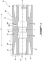
- FIG. 6 another embodiment of a journal bearing assembly 28 according to the present disclosure is shown, with like reference numerals referring to like features.
- the various characteristics, options and alternatives of the oil pocket 62 shown in FIGS. 4-5B and described above are also applicable to the oil pocket 62 of the journal bearing assembly shown in FIG. 6 , and vice-versa.
- the journal bearing assembly 28 may be referred to as a "pin-less" journal bearing assembly 28, as it does not include an insertable pin. Rather, the journal shaft 30 is structured to satisfy the functions of the pin 32 in the journal bearing assembly 28 shown in FIG. 3 .
- lubricating oil is directed directly into the inner cavity 50 of the journal shaft 30.
- the inner cavity 50 may thus include an oil inlet (for instance towards one of the axial ends of the inner cavity 50) and an oil outlet (at least one, illustratively two, oil passages 60).
- the shown oil passages 60 extend radially through the journal shaft 30 with inlet sections 60a in fluid communication with the inner cavity 50 and outlet sections 60b in fluid communication with the oil pocket 62 on the radially outer surface 54 of the journal shaft 30.
- the inner cavity 50 may be closed at one or both axial ends by a fastener such as a bolt 38 and a washer 40.
- journal bearing assembly having a journal shaft with an oil pocket on a radially outer surface thereof having with smooth and edgeless transitional surfaces, thereby allowing the risk of cavitation damage to various components of the journal bearing to be minimized.
- any maximum value, minimum value and/or ranges of values provided herein include(s) all values falling within the applicable manufacturing tolerances. Accordingly, in certain instances, these values may be varied by ⁇ 5%. In other implementations, these values may vary by as much as ⁇ 10%.
Landscapes
- Engineering & Computer Science (AREA)
- General Engineering & Computer Science (AREA)
- Mechanical Engineering (AREA)
- Chemical & Material Sciences (AREA)
- Combustion & Propulsion (AREA)
- Oil, Petroleum & Natural Gas (AREA)
- Chemical Kinetics & Catalysis (AREA)
- General Chemical & Material Sciences (AREA)
- Sliding-Contact Bearings (AREA)
Claims (13)
- Gleitwelle (30) für eine Gleitlagerbaugruppe (28) eines Flugzeugtriebwerks (10), umfassend:einen Wellenkörper, der sich entlang einer Längsachse (A) erstreckt, wobei der Wellenkörper eine radial äußere Fläche (54) und eine radial innere Fläche (52) aufweist, die radial von der Längsachse (A) beabstandet sind, um einen inneren Hohlraum (50) zu definieren; undeine Öltasche (62), die in der radial äußeren Fläche (54) definiert ist, einen oder mehrere Kanäle (60), die sich durch den Wellenkörper von der radial inneren Fläche (52) zu der Öltasche (62) erstrecken, um eine Fluidverbindung zwischen dem inneren Hohlraum (50) und der Öltasche (62) bereitzustellen, wobei die Öltasche (62) eine radial innere Basisfläche (66) und verbindende Übergangsflächen (68) beinhaltet, die sich zwischen der radial inneren Basisfläche (66) der Öltasche (62) und der radial äußeren Fläche (54) des Wellenkörpers erstrecken, wobei die verbindenden Übergangsflächen (68) einen fluiddynamisch glatten und kantenlosen Übergang zu der radial äußeren Fläche (54) der Gleitwelle (30) bilden,dadurch gekennzeichnet, dass:
die verbindenden Übergangsflächen (68) eine Tangente relativ zu der Längsachse (A) mit einem maximalen Winkel (θ) von etwa sechs Grad definieren. - Gleitwelle (30) nach Anspruch 1, wobei eine axiale Länge (L2) der verbindenden Übergangsflächen (68) zehn bis dreißig Prozent einer gesamten axialen Länge (L1) der radial inneren Basisfläche (66) einnimmt.
- Gleitwelle (30) nach Anspruch 1 oder 2, wobei die Tangente einen maximalen Winkel (θ) von ein bis vier Grad aufweist.
- Gleitwelle (30) nach einem der vorhergehenden Ansprüche, wobei die Öltasche (62) axial symmetrisch um eine Längsmitte (C) des Wellenkörpers ist.
- Gleitwelle (30) nach einem der vorhergehenden Ansprüche, wobei ein axiales Profil der verbindenden Übergangsflächen (68) durch eine lineare Funktion definiert ist.
- Gleitwelle (30) nach einem der Ansprüche 1 bis 4, wobei ein axiales Profil jeder der verbindenden Übergangsflächen (68) durch eine Polynomfunktion definiert ist.
- Gleitwelle (30) nach einem der Ansprüche 1 bis 4, wobei ein axiales Profil jeder der verbindenden Übergangsflächen (68) durch eine Sinusfunktion definiert ist.
- Gleitwelle (30) nach einem der Ansprüche 1 bis 4, wobei ein axiales Profil jeder der verbindenden Übergangsflächen (68) durch eine Doppelradiuskurve definiert ist.
- Gleitwelle (30) nach einem der vorhergehenden Ansprüche, wobei der innere Hohlraum (50) einen bolzenaufnehmenden inneren Hohlraum (50) definiert und die radial innere Fläche (52) mindestens eine umlaufende Ölkammer (58) beinhaltet, die in Fluidverbindung mit dem einen oder den mehreren Kanälen (60) steht.
- Gleitwelle (30) nach einem der vorhergehenden Ansprüche, wobei der eine oder die mehreren Kanäle (60), die sich durch den Wellenkörper erstrecken, sich in einer Richtung senkrecht zu der Längsachse (L) durch den Wellenkörper erstrecken.
- Gleitlagerbaugruppe (28) für ein Flugzeugtriebwerk (10), umfassend:eine Lagerhülse (34), die eine Bohrung definiert; unddie Gleitwelle (30) nach einem der vorhergehenden Ansprüche.
- Gleitlagerbaugruppe (28) nach Anspruch 11, ferner umfassend einen Bolzen (32), der in dem inneren Hohlraum (50) der Gleitwelle (30) angeordnet ist, wobei der Bolzen (32) einen inneren Bolzenhohlraum (36) aufweist, der über einen oder mehrere radiale Bolzenkanäle (44) in Fluidverbindung mit dem inneren Hohlraum (50) der Gleitwelle (30) steht.
- Gleitlagerbaugruppe (28) nach Anspruch 12, wobei der innere Hohlraum (50) der Gleitwelle (30) eine oder mehrere umlaufende Ölkammern (58) beinhaltet, die in Fluidverbindung mit dem einen oder den mehreren radialen Bolzenkanälen (44) und dem einen oder den mehreren Kanälen (60) stehen, die sich durch den Wellenkörper erstrecken.
Applications Claiming Priority (1)
| Application Number | Priority Date | Filing Date | Title |
|---|---|---|---|
| US17/656,975 US12084981B2 (en) | 2022-03-29 | 2022-03-29 | Journal bearing with oil pocket |
Publications (2)
| Publication Number | Publication Date |
|---|---|
| EP4253777A1 EP4253777A1 (de) | 2023-10-04 |
| EP4253777B1 true EP4253777B1 (de) | 2025-01-15 |
Family
ID=85778900
Family Applications (1)
| Application Number | Title | Priority Date | Filing Date |
|---|---|---|---|
| EP23164836.1A Active EP4253777B1 (de) | 2022-03-29 | 2023-03-28 | Gleitlager mit öltasche |
Country Status (3)
| Country | Link |
|---|---|
| US (1) | US12084981B2 (de) |
| EP (1) | EP4253777B1 (de) |
| CA (1) | CA3187614A1 (de) |
Families Citing this family (2)
| Publication number | Priority date | Publication date | Assignee | Title |
|---|---|---|---|---|
| US12429000B2 (en) * | 2023-08-08 | 2025-09-30 | Rtx Corporation | Elongated journal bearing for high gear ratio epicyclic fan drive gear system |
| US20250101893A1 (en) * | 2023-09-27 | 2025-03-27 | Honda Motor Co., Ltd. | Lubrication mechanism |
Family Cites Families (9)
| Publication number | Priority date | Publication date | Assignee | Title |
|---|---|---|---|---|
| US4553857A (en) | 1983-12-22 | 1985-11-19 | Ney Robert J | Reversible journal bearing uniflow lubrication system |
| WO1996007832A1 (en) | 1994-09-08 | 1996-03-14 | Kawasaki Jukogyo Kabushiki Kaisha | Reversing bearing device for double reversing propeller |
| US8690721B2 (en) | 2011-08-02 | 2014-04-08 | United Technologies Corporation | Journal pin oil supply for gear system |
| US9109628B2 (en) | 2013-09-13 | 2015-08-18 | Solar Turbines Incorporated | Journal bearing |
| US10851671B2 (en) | 2019-03-29 | 2020-12-01 | Pratt & Whitney Canada Corp. | Bending stiffening feature used for compliant journal bearing |
| US10935076B2 (en) * | 2019-05-03 | 2021-03-02 | Pratt & Whitney Canada Corp. | Journal bearing assembly with dual oil cavities |
| US11814975B2 (en) | 2021-08-20 | 2023-11-14 | Pratt & Whitney Canada Corp. | Feed circuit with slot(s) at interface between journal bearing and rotor |
| US11821364B2 (en) | 2021-08-20 | 2023-11-21 | Pratt & Whitney Canada Corp. | Shaped cavity at interface between journal bearing and rotor |
| DE102021122164A1 (de) | 2021-08-26 | 2023-03-02 | Rolls-Royce Deutschland Ltd & Co Kg | Gleitlager und Verfahren zum Schmieren und Kühlen eines Gleitlagers |
-
2022
- 2022-03-29 US US17/656,975 patent/US12084981B2/en active Active
-
2023
- 2023-01-25 CA CA3187614A patent/CA3187614A1/en active Pending
- 2023-03-28 EP EP23164836.1A patent/EP4253777B1/de active Active
Also Published As
| Publication number | Publication date |
|---|---|
| EP4253777A1 (de) | 2023-10-04 |
| US20230313706A1 (en) | 2023-10-05 |
| US12084981B2 (en) | 2024-09-10 |
| CA3187614A1 (en) | 2023-09-29 |
Similar Documents
| Publication | Publication Date | Title |
|---|---|---|
| US10935076B2 (en) | Journal bearing assembly with dual oil cavities | |
| EP3869064B1 (de) | Planetengetriebe mit nachgiebigen zapfenlagern | |
| US7269938B2 (en) | Counter-rotating gas turbine engine and method of assembling same | |
| US10767755B2 (en) | Planetary gearing and planet pin for a planetary gearing | |
| US8899916B2 (en) | Torque frame and asymmetric journal bearing for fan drive gear system | |
| US8894529B2 (en) | Journal pin oil supply for gear system | |
| US11209045B2 (en) | Dual land journal bearings for a compound planetary system | |
| EP4253777A1 (de) | Gleitlager mit öltasche | |
| GB2420381A (en) | Lubricating system for turbine engine. | |
| EP4137676B1 (de) | Geformter hohlraum an einer schnittstelle zwischen zapfenlager und rotor | |
| US10006520B2 (en) | System for regulating stresses in ring gears | |
| WO2018106335A1 (en) | Roller element bearing with preloaded hydrodynamic cage guides | |
| EP4124724A1 (de) | Wälzlageranordnung für einen gasturbinenmotor | |
| EP4137675B1 (de) | Speiseschaltung mit schlitz(en) an der schnittstelle zwischen dem gleitlager und dem rotor | |
| US20220213956A1 (en) | Planet carrier for a mechanical gearbox of an aircraft turbomachine | |
| EP3401562B1 (de) | Lager mit ungleichmässigem käfigspiel | |
| US11346393B2 (en) | No pin compliant journal bearing shaft for one part carrier | |
| US12352314B2 (en) | Air turbine starter with bearing support structure | |
| US12631140B1 (en) | Gearbox assembly for a turbine engine | |
| CA3109071A1 (en) | Dual land journal bearings for a compound planetary system | |
| US20260139624A1 (en) | Gearbox assembly for a turbine engine |
Legal Events
| Date | Code | Title | Description |
|---|---|---|---|
| PUAI | Public reference made under article 153(3) epc to a published international application that has entered the european phase |
Free format text: ORIGINAL CODE: 0009012 |
|
| STAA | Information on the status of an ep patent application or granted ep patent |
Free format text: STATUS: THE APPLICATION HAS BEEN PUBLISHED |
|
| AK | Designated contracting states |
Kind code of ref document: A1 Designated state(s): AL AT BE BG CH CY CZ DE DK EE ES FI FR GB GR HR HU IE IS IT LI LT LU LV MC ME MK MT NL NO PL PT RO RS SE SI SK SM TR |
|
| STAA | Information on the status of an ep patent application or granted ep patent |
Free format text: STATUS: REQUEST FOR EXAMINATION WAS MADE |
|
| 17P | Request for examination filed |
Effective date: 20240328 |
|
| RBV | Designated contracting states (corrected) |
Designated state(s): AL AT BE BG CH CY CZ DE DK EE ES FI FR GB GR HR HU IE IS IT LI LT LU LV MC ME MK MT NL NO PL PT RO RS SE SI SK SM TR |
|
| GRAP | Despatch of communication of intention to grant a patent |
Free format text: ORIGINAL CODE: EPIDOSNIGR1 |
|
| STAA | Information on the status of an ep patent application or granted ep patent |
Free format text: STATUS: GRANT OF PATENT IS INTENDED |
|
| INTG | Intention to grant announced |
Effective date: 20240801 |
|
| GRAS | Grant fee paid |
Free format text: ORIGINAL CODE: EPIDOSNIGR3 |
|
| GRAA | (expected) grant |
Free format text: ORIGINAL CODE: 0009210 |
|
| STAA | Information on the status of an ep patent application or granted ep patent |
Free format text: STATUS: THE PATENT HAS BEEN GRANTED |
|
| AK | Designated contracting states |
Kind code of ref document: B1 Designated state(s): AL AT BE BG CH CY CZ DE DK EE ES FI FR GB GR HR HU IE IS IT LI LT LU LV MC ME MK MT NL NO PL PT RO RS SE SI SK SM TR |
|
| REG | Reference to a national code |
Ref country code: CH Ref legal event code: EP Ref country code: GB Ref legal event code: FG4D |
|
| REG | Reference to a national code |
Ref country code: DE Ref legal event code: R096 Ref document number: 602023001637 Country of ref document: DE |
|
| REG | Reference to a national code |
Ref country code: IE Ref legal event code: FG4D |
|
| PGFP | Annual fee paid to national office [announced via postgrant information from national office to epo] |
Ref country code: AT Payment date: 20250417 Year of fee payment: 3 |
|
| REG | Reference to a national code |
Ref country code: NL Ref legal event code: MP Effective date: 20250115 |
|
| PG25 | Lapsed in a contracting state [announced via postgrant information from national office to epo] |
Ref country code: NL Free format text: LAPSE BECAUSE OF FAILURE TO SUBMIT A TRANSLATION OF THE DESCRIPTION OR TO PAY THE FEE WITHIN THE PRESCRIBED TIME-LIMIT Effective date: 20250115 |
|
| PG25 | Lapsed in a contracting state [announced via postgrant information from national office to epo] |
Ref country code: RS Free format text: LAPSE BECAUSE OF FAILURE TO SUBMIT A TRANSLATION OF THE DESCRIPTION OR TO PAY THE FEE WITHIN THE PRESCRIBED TIME-LIMIT Effective date: 20250415 |
|
| PG25 | Lapsed in a contracting state [announced via postgrant information from national office to epo] |
Ref country code: FI Free format text: LAPSE BECAUSE OF FAILURE TO SUBMIT A TRANSLATION OF THE DESCRIPTION OR TO PAY THE FEE WITHIN THE PRESCRIBED TIME-LIMIT Effective date: 20250115 |
|
| PG25 | Lapsed in a contracting state [announced via postgrant information from national office to epo] |
Ref country code: PL Free format text: LAPSE BECAUSE OF FAILURE TO SUBMIT A TRANSLATION OF THE DESCRIPTION OR TO PAY THE FEE WITHIN THE PRESCRIBED TIME-LIMIT Effective date: 20250115 |
|
| PG25 | Lapsed in a contracting state [announced via postgrant information from national office to epo] |
Ref country code: ES Free format text: LAPSE BECAUSE OF FAILURE TO SUBMIT A TRANSLATION OF THE DESCRIPTION OR TO PAY THE FEE WITHIN THE PRESCRIBED TIME-LIMIT Effective date: 20250115 |
|
| REG | Reference to a national code |
Ref country code: LT Ref legal event code: MG9D |
|
| PG25 | Lapsed in a contracting state [announced via postgrant information from national office to epo] |
Ref country code: NO Free format text: LAPSE BECAUSE OF FAILURE TO SUBMIT A TRANSLATION OF THE DESCRIPTION OR TO PAY THE FEE WITHIN THE PRESCRIBED TIME-LIMIT Effective date: 20250415 Ref country code: IS Free format text: LAPSE BECAUSE OF FAILURE TO SUBMIT A TRANSLATION OF THE DESCRIPTION OR TO PAY THE FEE WITHIN THE PRESCRIBED TIME-LIMIT Effective date: 20250515 |
|
| REG | Reference to a national code |
Ref country code: AT Ref legal event code: MK05 Ref document number: 1760010 Country of ref document: AT Kind code of ref document: T Effective date: 20250115 |
|
| PG25 | Lapsed in a contracting state [announced via postgrant information from national office to epo] |
Ref country code: HR Free format text: LAPSE BECAUSE OF FAILURE TO SUBMIT A TRANSLATION OF THE DESCRIPTION OR TO PAY THE FEE WITHIN THE PRESCRIBED TIME-LIMIT Effective date: 20250115 |
|
| PG25 | Lapsed in a contracting state [announced via postgrant information from national office to epo] |
Ref country code: LV Free format text: LAPSE BECAUSE OF FAILURE TO SUBMIT A TRANSLATION OF THE DESCRIPTION OR TO PAY THE FEE WITHIN THE PRESCRIBED TIME-LIMIT Effective date: 20250115 Ref country code: PT Free format text: LAPSE BECAUSE OF FAILURE TO SUBMIT A TRANSLATION OF THE DESCRIPTION OR TO PAY THE FEE WITHIN THE PRESCRIBED TIME-LIMIT Effective date: 20250515 |
|
| PG25 | Lapsed in a contracting state [announced via postgrant information from national office to epo] |
Ref country code: GR Free format text: LAPSE BECAUSE OF FAILURE TO SUBMIT A TRANSLATION OF THE DESCRIPTION OR TO PAY THE FEE WITHIN THE PRESCRIBED TIME-LIMIT Effective date: 20250416 Ref country code: BG Free format text: LAPSE BECAUSE OF FAILURE TO SUBMIT A TRANSLATION OF THE DESCRIPTION OR TO PAY THE FEE WITHIN THE PRESCRIBED TIME-LIMIT Effective date: 20250115 |
|
| PG25 | Lapsed in a contracting state [announced via postgrant information from national office to epo] |
Ref country code: AT Free format text: LAPSE BECAUSE OF FAILURE TO SUBMIT A TRANSLATION OF THE DESCRIPTION OR TO PAY THE FEE WITHIN THE PRESCRIBED TIME-LIMIT Effective date: 20250115 |
|
| PG25 | Lapsed in a contracting state [announced via postgrant information from national office to epo] |
Ref country code: SE Free format text: LAPSE BECAUSE OF FAILURE TO SUBMIT A TRANSLATION OF THE DESCRIPTION OR TO PAY THE FEE WITHIN THE PRESCRIBED TIME-LIMIT Effective date: 20250115 |
|
| PG25 | Lapsed in a contracting state [announced via postgrant information from national office to epo] |
Ref country code: SM Free format text: LAPSE BECAUSE OF FAILURE TO SUBMIT A TRANSLATION OF THE DESCRIPTION OR TO PAY THE FEE WITHIN THE PRESCRIBED TIME-LIMIT Effective date: 20250115 |
|
| PG25 | Lapsed in a contracting state [announced via postgrant information from national office to epo] |
Ref country code: DK Free format text: LAPSE BECAUSE OF FAILURE TO SUBMIT A TRANSLATION OF THE DESCRIPTION OR TO PAY THE FEE WITHIN THE PRESCRIBED TIME-LIMIT Effective date: 20250115 |
|
| PG25 | Lapsed in a contracting state [announced via postgrant information from national office to epo] |
Ref country code: MC Free format text: LAPSE BECAUSE OF FAILURE TO SUBMIT A TRANSLATION OF THE DESCRIPTION OR TO PAY THE FEE WITHIN THE PRESCRIBED TIME-LIMIT Effective date: 20250115 |
|
| PG25 | Lapsed in a contracting state [announced via postgrant information from national office to epo] |
Ref country code: IT Free format text: LAPSE BECAUSE OF FAILURE TO SUBMIT A TRANSLATION OF THE DESCRIPTION OR TO PAY THE FEE WITHIN THE PRESCRIBED TIME-LIMIT Effective date: 20250115 |
|
| REG | Reference to a national code |
Ref country code: DE Ref legal event code: R097 Ref document number: 602023001637 Country of ref document: DE |
|
| PG25 | Lapsed in a contracting state [announced via postgrant information from national office to epo] |
Ref country code: EE Free format text: LAPSE BECAUSE OF FAILURE TO SUBMIT A TRANSLATION OF THE DESCRIPTION OR TO PAY THE FEE WITHIN THE PRESCRIBED TIME-LIMIT Effective date: 20250115 Ref country code: CZ Free format text: LAPSE BECAUSE OF FAILURE TO SUBMIT A TRANSLATION OF THE DESCRIPTION OR TO PAY THE FEE WITHIN THE PRESCRIBED TIME-LIMIT Effective date: 20250115 |
|
| PG25 | Lapsed in a contracting state [announced via postgrant information from national office to epo] |
Ref country code: RO Free format text: LAPSE BECAUSE OF FAILURE TO SUBMIT A TRANSLATION OF THE DESCRIPTION OR TO PAY THE FEE WITHIN THE PRESCRIBED TIME-LIMIT Effective date: 20250115 |
|
| PG25 | Lapsed in a contracting state [announced via postgrant information from national office to epo] |
Ref country code: SK Free format text: LAPSE BECAUSE OF FAILURE TO SUBMIT A TRANSLATION OF THE DESCRIPTION OR TO PAY THE FEE WITHIN THE PRESCRIBED TIME-LIMIT Effective date: 20250115 |
|
| PG25 | Lapsed in a contracting state [announced via postgrant information from national office to epo] |
Ref country code: LU Free format text: LAPSE BECAUSE OF NON-PAYMENT OF DUE FEES Effective date: 20250328 |
|
| PLBE | No opposition filed within time limit |
Free format text: ORIGINAL CODE: 0009261 |
|
| STAA | Information on the status of an ep patent application or granted ep patent |
Free format text: STATUS: NO OPPOSITION FILED WITHIN TIME LIMIT |
|
| REG | Reference to a national code |
Ref country code: BE Ref legal event code: MM Effective date: 20250331 |
|
| 26N | No opposition filed |
Effective date: 20251016 |
|
| PG25 | Lapsed in a contracting state [announced via postgrant information from national office to epo] |
Ref country code: BE Free format text: LAPSE BECAUSE OF NON-PAYMENT OF DUE FEES Effective date: 20250331 |
|
| PG25 | Lapsed in a contracting state [announced via postgrant information from national office to epo] |
Ref country code: IE Free format text: LAPSE BECAUSE OF NON-PAYMENT OF DUE FEES Effective date: 20250328 |
|
| PGFP | Annual fee paid to national office [announced via postgrant information from national office to epo] |
Ref country code: DE Payment date: 20260219 Year of fee payment: 4 |
|
| PGFP | Annual fee paid to national office [announced via postgrant information from national office to epo] |
Ref country code: FR Payment date: 20260219 Year of fee payment: 4 |