EP4253759A1 - Flow path switching device and method for preventing dry running of submerged-type pump - Google Patents
Flow path switching device and method for preventing dry running of submerged-type pump Download PDFInfo
- Publication number
- EP4253759A1 EP4253759A1 EP21897428.5A EP21897428A EP4253759A1 EP 4253759 A1 EP4253759 A1 EP 4253759A1 EP 21897428 A EP21897428 A EP 21897428A EP 4253759 A1 EP4253759 A1 EP 4253759A1
- Authority
- EP
- European Patent Office
- Prior art keywords
- flow passage
- gas
- submersible pump
- suction vessel
- suction
- Prior art date
- Legal status (The legal status is an assumption and is not a legal conclusion. Google has not performed a legal analysis and makes no representation as to the accuracy of the status listed.)
- Pending
Links
Images






Classifications
-
- F—MECHANICAL ENGINEERING; LIGHTING; HEATING; WEAPONS; BLASTING
- F04—POSITIVE - DISPLACEMENT MACHINES FOR LIQUIDS; PUMPS FOR LIQUIDS OR ELASTIC FLUIDS
- F04D—NON-POSITIVE-DISPLACEMENT PUMPS
- F04D9/00—Priming; Preventing vapour lock
- F04D9/001—Preventing vapour lock
- F04D9/002—Preventing vapour lock by means in the very pump
- F04D9/003—Preventing vapour lock by means in the very pump separating and removing the vapour
-
- F—MECHANICAL ENGINEERING; LIGHTING; HEATING; WEAPONS; BLASTING
- F04—POSITIVE - DISPLACEMENT MACHINES FOR LIQUIDS; PUMPS FOR LIQUIDS OR ELASTIC FLUIDS
- F04D—NON-POSITIVE-DISPLACEMENT PUMPS
- F04D13/00—Pumping installations or systems
- F04D13/02—Units comprising pumps and their driving means
- F04D13/06—Units comprising pumps and their driving means the pump being electrically driven
- F04D13/08—Units comprising pumps and their driving means the pump being electrically driven for submerged use
-
- F—MECHANICAL ENGINEERING; LIGHTING; HEATING; WEAPONS; BLASTING
- F04—POSITIVE - DISPLACEMENT MACHINES FOR LIQUIDS; PUMPS FOR LIQUIDS OR ELASTIC FLUIDS
- F04D—NON-POSITIVE-DISPLACEMENT PUMPS
- F04D13/00—Pumping installations or systems
- F04D13/02—Units comprising pumps and their driving means
- F04D13/06—Units comprising pumps and their driving means the pump being electrically driven
- F04D13/08—Units comprising pumps and their driving means the pump being electrically driven for submerged use
- F04D13/086—Units comprising pumps and their driving means the pump being electrically driven for submerged use the pump and drive motor are both submerged
-
- F—MECHANICAL ENGINEERING; LIGHTING; HEATING; WEAPONS; BLASTING
- F04—POSITIVE - DISPLACEMENT MACHINES FOR LIQUIDS; PUMPS FOR LIQUIDS OR ELASTIC FLUIDS
- F04D—NON-POSITIVE-DISPLACEMENT PUMPS
- F04D15/00—Control, e.g. regulation, of pumps, pumping installations or systems
- F04D15/0005—Control, e.g. regulation, of pumps, pumping installations or systems by using valves
- F04D15/0011—Control, e.g. regulation, of pumps, pumping installations or systems by using valves by-pass valves
-
- F—MECHANICAL ENGINEERING; LIGHTING; HEATING; WEAPONS; BLASTING
- F04—POSITIVE - DISPLACEMENT MACHINES FOR LIQUIDS; PUMPS FOR LIQUIDS OR ELASTIC FLUIDS
- F04D—NON-POSITIVE-DISPLACEMENT PUMPS
- F04D29/00—Details, component parts, or accessories
- F04D29/40—Casings; Connections of working fluid
- F04D29/42—Casings; Connections of working fluid for radial or helico-centrifugal pumps
- F04D29/44—Fluid-guiding means, e.g. diffusers
-
- F—MECHANICAL ENGINEERING; LIGHTING; HEATING; WEAPONS; BLASTING
- F04—POSITIVE - DISPLACEMENT MACHINES FOR LIQUIDS; PUMPS FOR LIQUIDS OR ELASTIC FLUIDS
- F04D—NON-POSITIVE-DISPLACEMENT PUMPS
- F04D29/00—Details, component parts, or accessories
- F04D29/40—Casings; Connections of working fluid
- F04D29/42—Casings; Connections of working fluid for radial or helico-centrifugal pumps
- F04D29/44—Fluid-guiding means, e.g. diffusers
- F04D29/445—Fluid-guiding means, e.g. diffusers especially adapted for liquid pumps
-
- F—MECHANICAL ENGINEERING; LIGHTING; HEATING; WEAPONS; BLASTING
- F04—POSITIVE - DISPLACEMENT MACHINES FOR LIQUIDS; PUMPS FOR LIQUIDS OR ELASTIC FLUIDS
- F04D—NON-POSITIVE-DISPLACEMENT PUMPS
- F04D7/00—Pumps adapted for handling specific fluids, e.g. by selection of specific materials for pumps or pump parts
- F04D7/02—Pumps adapted for handling specific fluids, e.g. by selection of specific materials for pumps or pump parts of centrifugal type
-
- F—MECHANICAL ENGINEERING; LIGHTING; HEATING; WEAPONS; BLASTING
- F04—POSITIVE - DISPLACEMENT MACHINES FOR LIQUIDS; PUMPS FOR LIQUIDS OR ELASTIC FLUIDS
- F04D—NON-POSITIVE-DISPLACEMENT PUMPS
- F04D1/00—Radial-flow pumps, e.g. centrifugal pumps; Helico-centrifugal pumps
- F04D1/06—Multi-stage pumps
-
- F—MECHANICAL ENGINEERING; LIGHTING; HEATING; WEAPONS; BLASTING
- F05—INDEXING SCHEMES RELATING TO ENGINES OR PUMPS IN VARIOUS SUBCLASSES OF CLASSES F01-F04
- F05D—INDEXING SCHEME FOR ASPECTS RELATING TO NON-POSITIVE-DISPLACEMENT MACHINES OR ENGINES, GAS-TURBINES OR JET-PROPULSION PLANTS
- F05D2250/00—Geometry
- F05D2250/50—Inlet or outlet
- F05D2250/52—Outlet
Definitions
- FIG. 2 shows a state of the fluid-path switching apparatus 5 when the submersible pump 1 is not in operation.
- the valve element 47 is pressed against the flow-passage structure 45 by a spring 50 to thereby close the first flow passage 41.
- the flow-passage structure 45 has a valve seat 51 formed around an outlet of the first flow passage 41, and the valve element 47 is pressed against the valve seat 51 by the spring 50. Therefore, when the valve element 47 is pressed against the valve seat 51, the first flow passage 41 is closed, while the second flow passage 42 and the third flow passage 43 are in fluid communication.
- the second flow passage 42 is open in the suction vessel 2 and communicates with the suction port 7 through the interior of the suction vessel 2.
Landscapes
- Engineering & Computer Science (AREA)
- Mechanical Engineering (AREA)
- General Engineering & Computer Science (AREA)
- Structures Of Non-Positive Displacement Pumps (AREA)
Abstract
Description
- The present invention relates to a technique of preventing idling rotation of a submersible pump used for delivering liquefied gas, such as liquefied ammonia, liquid hydrogen, liquid nitrogen, liquefied natural gas, liquefied ethylene gas, or liquefied petroleum gas.
- Natural gas is widely used for thermal power generation and as a raw material for chemicals. Furthermore, ammonia and hydrogen are expected to be energies that do not generate carbon dioxide that causes global warming. Applications of hydrogen as an energy include fuel cell and turbine power generation. Natural gas, ammonia, and hydrogen are in a gaseous state at normal temperature, and therefore natural gas, ammonia, and hydrogen are cooled and liquefied for their storage and transportation. Liquefied gas, such as liquefied natural gas (LNG), liquefied ammonia, and liquefied hydrogen, is temporarily stored in a liquefied-gas storage tank and then delivered to a power plant, factory, or the like by a pump.
-
FIG. 12 is a schematic diagram showing a conventional example of a pump system for pumping up liquefied gas. Apump 500 is installed in avertical suction vessel 505, which is coupled to a liquefied-gas storage tank (not shown) in which the liquefied gas is stored. The liquefied gas is introduced into thesuction vessel 505 through asuction port 501, and thesuction vessel 505 is filled with the liquefied gas. Theentire pump 500 is immersed in the liquefied gas. Therefore, thepump 500 is a submersible pump that can operate in the liquefied gas. When thepump 500 is operated, the liquefied gas is discharged by thepump 500 through adischarge port 502. During the operation of thepump 500, a part of the liquefied gas in thesuction vessel 505 vaporizes into gas, which is exhausted from thesuction vessel 505 through avent line 503. - Before the
pump 500 is operated, a drying-up operation of purging air out from thesuction vessel 505 with purge gas and a cooling-down operation of cooling thepump 500 with liquefied gas are performed. If the air present in thesuction vessel 505 comes into contact with the ultra-low temperature liquefied gas, moisture in the air is cooled and solidified by the liquefied gas, which may impede the rotation of thepump 500. Furthermore, if thepump 500 is at a normal temperature when thepump 500 is started, the ultra-low temperature liquefied gas will vaporize when the liquefied gas contacts thepump 500. In order to prevent such events, the drying-up operation and the cooling-down operation are performed before thepump 500 is operated. - The drying-up operation includes injecting a purge gas (e.g., nitrogen gas) into the
suction vessel 505, and the cooling-down operation includes injecting a liquefied gas (e.g., liquefied natural gas) into thesuction vessel 505. The purge gas or the liquefied gas injected into thesuction vessel 505 fills thesuction vessel 505, flows into thepump 500 through aninlet 500a of thepump 500, and is discharged through thedischarge port 502. -
- Patent document 1:
Japanese laid-open utility model publication No. S59-159795 - Patent document 2:
Japanese examined utility model publication No. S62-031680 - However, the purge gas that has been supplied into the
suction vessel 505 for the drying-up operation flows through thepump 500 and may cause idling rotation (or free rotation) of thepump 500. When thepump 500 is forced to idle by the purge gas, sliding parts, such as bearings, may be damaged. Furthermore, the liquefied gas that has been supplied into thesuction vessel 505 for the cooling-down operation comes into contact with the normal-temperature pump 500, thus forming a large amount of gas. This gas may cause idling rotation of an impeller of thepump 500, which may cause damage to sliding parts, such as bearings. - Accordingly, the present invention provides a fluid-path switching apparatus capable of preventing idling rotation of a pump due to gas introduced into a suction vessel for the purpose of a drying-up operation or a cooling-down operation for the pump. The present invention also provides a method of preventing idling rotation of a submersible pump.
- In an embodiment, there is provided a fluid-path switching apparatus for preventing idling rotation of a submersible pump disposed in a suction vessel and used for delivering liquefied gas, comprising: a flow-passage structure having a first flow passage, a second flow passage, and a third flow passage; and a valve element arranged in the flow-passage structure, the valve element being configured to allow the third flow passage to selectively communicate with either the first flow passage or the second flow passage, the first flow passage communicating with a discharge outlet of the submersible pump, the second flow passage communicating with an interior of the suction vessel, and the third flow passage communicating with a discharge port of the suction vessel.
- In an embodiment, the flow-passage structure further includes a bypass passage that establishes fluid communication between the first flow passage and the third flow passage, and the bypass passage has a cross-sectional area smaller than a cross-sectional area of the first flow passage.
- In an embodiment, the cross-sectional area of the bypass passage is such that an impeller of the submersible pump does not rotate due to flow of gas when the valve element closes the first flow passage and the gas flows through the submersible pump and the bypass passage.
- In an embodiment, the fluid-path switching apparatus further comprises a spring configured to press the valve element against the flow-passage structure to close the first flow passage.
- In an embodiment, there is provided a pump system comprising: a submersible pump configured to deliver liquefied gas; a suction vessel in which the submersible pump is accommodated; and the fluid-path switching apparatus for preventing idling rotation of the submersible pump.
- In an embodiment, the pump system further comprises a rotation detector configured to detect rotation of the submersible pump.
- In an embodiment, the pump system further comprises an anti-rotation device configured to prevent rotation of the submersible pump.
- In an embodiment, there is provided a method of preventing idling rotation of a submersible pump disposed in a suction vessel and used for delivering liquefied gas, comprising: supplying liquefied gas into the suction vessel when a first flow passage is closed with a valve element, and a second flow passage and a third flow passage are in fluid communication, the first flow passage communicating with a discharge outlet of the submersible pump, the second flow passage communicating with an interior of the suction vessel, the third flow passage communicating with a discharge port of the suction vessel; and delivering gas generated in the suction vessel to the discharge port through the second flow passage and the third flow passage.
- In an embodiment, the method further comprises supplying purge gas into the suction vessel before supplying the liquefied gas into the suction vessel.
- In an embodiment, the purge gas is supplied into the suction vessel through a suction port of the suction vessel and discharged through a drain line coupled to a bottom of the suction vessel, the suction port being located higher than the bottom of the suction vessel.
- In an embodiment, the purge gas is supplied into the suction vessel through a suction port of the suction vessel and discharged through the second flow passage, the third flow passage, and the discharge port.
- In an embodiment, the purge gas is supplied into the suction vessel through a drain line coupled to a bottom of the suction vessel and discharged through the second flow passage, the third flow passage, and the discharge port.
- In an embodiment, the purge gas is an inert gas composed of element having a boiling point lower than that of an element constituting the liquefied gas.
- In an embodiment, the method further comprises operating the submersible pump in a state in which the second flow passage is closed by the valve element and the first flow passage communicates with the third flow passage.
- In an embodiment, the method further comprises directing gas generated in the suction vessel through the discharge port to a gas treatment device.
- According to the present invention, gas (e.g., purge gas, or gas generated from liquefied gas, etc.) that has been introduced into the suction vessel during a drying-up operation or a cooling-down operation does not flow into the submersible pump because of the fluid-path switching apparatus, so that the gas is led to the discharge port. Therefore, the impeller of the submersible pump is not forced to idle (or rotate freely), and as a result, damage to sliding parts, such as bearings of the submersible pump, can be prevented.
-
- [
FIG. 1] FIG. 1 shows an embodiment of a pump system for delivering liquefied gas; - [
FIG. 2] FIG. 2 is a cross-sectional view showing an embodiment of detailed configurations of a fluid-path switching apparatus; - [
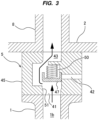
FIG. 3] FIG. 3 shows a state of the fluid-path switching apparatus when a submersible pump is in operation; - [
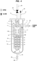
FIG. 4] FIG. 4 is a diagram for explaining an embodiment of a drying-up operation; - [
FIG. 5] FIG. 5 is a diagram for explaining another embodiment of the drying-up operation; - [
FIG. 6] FIG. 6 is a diagram for explaining still another embodiment of the drying-up operation; - [
FIG. 7] FIG. 7 is a diagram for explaining an embodiment of a cooling-down operation; - [
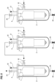
FIG. 8] FIG. 8 is a diagram for explaining an embodiment of simultaneously cooling a plurality of submersible pumps; - [
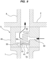
FIG. 9] FIG. 9 is a cross-sectional view showing another embodiment of the fluid-path switching apparatus; - [
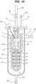
FIG. 10] FIG. 10 shows an embodiment of a pump system including a rotation detector; - [
FIG. 11] FIG. 11 shows an embodiment of a pump system including an anti-rotation device; and - [
FIG. 12] FIG. 12 is a schematic diagram showing a conventional example of a pump system for pumping up liquefied gas. - Hereinafter, embodiments of the present invention will be described with reference to the drawings.
FIG. 1 illustrates an embodiment of a pump system for delivering liquefied gas. Examples of the liquefied gas to be delivered by the pump system shown inFIG. 1 include liquefied ammonia, liquid hydrogen, liquid nitrogen, liquefied natural gas, liquefied ethylene gas, liquefied petroleum gas, and the like. - As shown in
FIG. 1 , the pump system includes asubmersible pump 1 for delivering the liquefied gas, asuction vessel 2 in which thesubmersible pump 1 is accommodated, and a fluid-path switching apparatus 5 for preventing idling rotation of thesubmersible pump 1. Thesuction vessel 2 has asuction port 7 and adischarge port 8. The liquefied gas is introduced through thesuction port 7 into thesuction vessel 2, and an interior of thesuction vessel 2 is filled with the liquefied gas. During operation of thesubmersible pump 1, the entiresubmersible pump 1 is immersed in the liquefied gas. Therefore, thesubmersible pump 1 is configured to be operable in the liquefied gas. - The
submersible pump 1 includes anelectric motor 11 having amotor rotor 11A and amotor stator 11B, arotation shaft 12 coupled to theelectric motor 11,bearings rotation shaft 12, animpeller 15 secured to therotation shaft 12, and apump casing 16 in which theimpeller 15 is housed. The fluid-path switching apparatus 5 is arranged in thesuction vessel 2. More specifically, the fluid-path switching apparatus 5 is coupled to both adischarge outlet 1b of thesubmersible pump 1 and thedischarge port 8 of thesuction vessel 2. Specific configurations of the fluid-path switching apparatus 5 will be described later. - When electric power is supplied to the
electric motor 11 through a power cable (not shown), theelectric motor 11 rotates therotation shaft 12 and theimpeller 15 together. As theimpeller 15 rotates, the liquefied gas is sucked into thesubmersible pump 1 through asuction inlet 1a of thesubmersible pump 1, flows through adischarge flow passage 17 and thedischarge outlet 1b, and is discharged into the fluid-path switching apparatus 5. Further, the liquefied gas flows through the fluid-path switching apparatus 5 into thedischarge port 8 of thesuction vessel 2. Adischarge pipe 20 is coupled to thedischarge port 8, so that the liquefied gas that has flowed through thedischarge port 8 is delivered through thedischarge pipe 20. - A
suction valve 22 is coupled to thesuction port 7, and adischarge valve 23 is coupled to thedischarge port 8. Adrain line 25 is coupled to a bottom of thesuction vessel 2, and adrain valve 26 is coupled to thedrain line 25. Thesuction port 7 is provided on a side wall of thesuction vessel 2 and is located higher than the bottom of thesuction vessel 2. Thedischarge port 8 is provided on an upper portion of thesuction vessel 2 and is located higher than thesuction port 7. During operation of thesubmersible pump 1, thesuction valve 22 and thedischarge valve 23 are open, and thedrain valve 26 is closed. Avent line 31 is coupled to the upper portion of thesuction vessel 2. During operation of thesubmersible pump 1, a part of the liquefied gas evaporates into gas due to heat generation of thesubmersible pump 1. This gas is discharged from thesuction vessel 2 through thevent line 31. Avent valve 32 is coupled to thevent line 31. In one embodiment, this gas may be delivered through thevent line 31 to a gas treatment device (not shown). The gas treatment device is configured to treat the gas (e.g., natural gas, hydrogen gas, or ammonia gas) vaporized from the liquefied gas. Examples of the gas treatment device include gas incinerator (flaring device), chemical gas treatment device, gas adsorption device, and the like. -
FIG. 2 is a cross-sectional view showing an embodiment of detailed configurations of the fluid-path switching apparatus 5. As shown inFIG. 2 , the fluid-path switching apparatus 5 includes a flow-passage structure 45 having afirst flow passage 41, asecond flow passage 42, and athird flow passage 43, and avalve element 47 arranged in the flow-passage structure 45. Thefirst flow passage 41 communicates with thedischarge outlet 1b of thesubmersible pump 1, thesecond flow passage 42 communicates with the interior of thesuction vessel 2, and thethird flow passage 43 communicates with thedischarge port 8 of thesuction vessel 2. Thevalve element 47 is arranged so as to allow thethird flow passage 43 to selectively communicate with either thefirst flow passage 41 or thesecond flow passage 42. The configurations of the fluid-path switching apparatus 5 are not limited to the embodiment shown inFIG. 2 as long as its intended function can be achieved. -
FIG. 2 shows a state of the fluid-path switching apparatus 5 when thesubmersible pump 1 is not in operation. Thevalve element 47 is pressed against the flow-passage structure 45 by aspring 50 to thereby close thefirst flow passage 41. More specifically, the flow-passage structure 45 has avalve seat 51 formed around an outlet of thefirst flow passage 41, and thevalve element 47 is pressed against thevalve seat 51 by thespring 50. Therefore, when thevalve element 47 is pressed against thevalve seat 51, thefirst flow passage 41 is closed, while thesecond flow passage 42 and thethird flow passage 43 are in fluid communication. Thesecond flow passage 42 is open in thesuction vessel 2 and communicates with thesuction port 7 through the interior of thesuction vessel 2. -
FIG. 3 shows a state of the fluid-path switching apparatus 5 when thesubmersible pump 1 is in operation. When thesubmersible pump 1 is in operation, the liquefied gas is discharged from thedischarge outlet 1b of thesubmersible pump 1 and flows into thefirst flow passage 41 of the fluid-path switching apparatus 5. The liquefied gas flowing through thefirst flow passage 41 moves thevalve element 47 against the force of thespring 50 to open thefirst flow passage 41 and close thesecond flow passage 42 with thevalve element 47. As a result, thefirst flow passage 41 and thethird flow passage 43 communicate with each other. - When the operation of the
submersible pump 1 is stopped, thevalve element 47 is pressed against thevalve seat 51 by thespring 50. As a result, as shown inFIG. 2 , thefirst flow passage 41 is closed, and thesecond flow passage 42 and thethird flow passage 43 communicate with each other. In this manner, the fluid-path switching apparatus 5 of this embodiment operates only by thespring 50 and the flow of the liquefied gas. In one embodiment, the fluid-path switching apparatus 5 may have an actuator (for example, an electrical actuator or a hydraulic actuator) configured to move thevalve element 47. - Before the operation of the
submersible pump 1 is started, a drying-up operation is performed which is to remove air from thesuction vessel 2 with purge gas, and a cooling-down operation is performed which is to cool thesubmersible pump 1 with the liquefied gas. The drying-up operation and the cooling-down operation are performed in the state shown inFIG. 2 , i.e., in the state in which thefirst flow passage 41 is closed with thevalve element 47, and thesecond flow passage 42 and thethird flow passage 43 are in fluid communication. - The drying-up operation is an operation of introducing purge gas having a normal temperature into the
suction vessel 2 to dry thesubmersible pump 1. An embodiment of the drying-up operation will be described below with reference toFIG. 4 . The purge gas is delivered through thesuction port 7 into thesuction vessel 2 while thesubmersible pump 1 is not in operation (i.e., the state shown inFIG. 2 ). Thedischarge valve 23 and thevent valve 32 are closed, and thesuction valve 22 and thedrain valve 26 are open. Thevent valve 32 may be open. The purge gas purges the air present in thesuction vessel 2 and is discharged together with the air through thedrain line 25. The interior of thesuction vessel 2 is filled with the purge gas, which dries thesubmersible pump 1. - In one embodiment, the drying-up operation may be performed as follows. As shown in
FIG. 5 , when thesubmersible pump 1 is not in operation (i.e., the state shown inFIG. 2 ), the purge gas is delivered through thesuction port 7 into thesuction vessel 2. Thedrain valve 26 and thevent valve 32 are closed, and thesuction valve 22 and thedischarge valve 23 are open. Thevent valve 32 may be open. The purge gas purges the air present in thesuction vessel 2 and is discharged together with the air through thesecond flow passage 42 and thethird flow passage 43 of the fluid-path switching apparatus 5 and thedischarge port 8. The interior of thesuction vessel 2 is filled with the purge gas, which dries thesubmersible pump 1. - Furthermore, in one embodiment, the drying-up operation may be performed as follows. As shown in
FIG. 6 , when thesubmersible pump 1 is not in operation (i.e., the state shown inFIG. 2 ), the purge gas is delivered through thedrain line 25 into thesuction vessel 2. Thesuction valve 22 and thevent valve 32 are closed, and thedrain valve 26 and thedischarge valve 23 are open. Thevent valve 32 may be open. The purge gas purges the air present in thesuction vessel 2 and is discharged together with the air through thesecond flow passage 42 and thethird flow passage 43 of the fluid-path switching apparatus 5 and thedischarge port 8. The interior of thesuction vessel 2 is filled with the purge gas, which dries thesubmersible pump 1. - In the embodiments shown in
FIGS. 4 to 6 , thefirst flow passage 41 is closed by thevalve element 47. Therefore, the purge gas introduced into thesuction vessel 2 does not flow through thesubmersible pump 1. As a result, idling rotation of theimpeller 15 of thesubmersible pump 1 is prevented, and sliding parts, such as thebearings - The purge gas used for the drying-up operation is an inert gas composed of element having a boiling point lower than that of an element constituting the liquefied gas. This is to prevent the purge gas from being liquefied when the purge gas comes into contact with the cryogenic liquefied gas introduced after the drying-up operation. For example, if the liquefied gas is liquefied natural gas (LNG) or liquefied ammonia, the purge gas used is nitrogen gas. In another example, if the liquefied gas is liquid hydrogen, the purge gas used is helium gas.
- The cooling-down operation is an operation of introducing the liquefied gas into the
suction vessel 2 to cool thesubmersible pump 1 after the drying-up operation. An embodiment of the cooling-down operation will be described below with reference toFIG. 7 . As shown inFIG. 7 , when thesubmersible pump 1 is not in operation (i.e., the state shown inFIG. 2 ), the liquefied gas is delivered through thesuction port 7 into thesuction vessel 2. Thedrain valve 26 and thevent valve 32 are closed, and thesuction valve 22 and thedischarge valve 23 are open. Thevent valve 32 may be open. The liquefied gas comes into contact with thesubmersible pump 1 and thesuction vessel 2 each having a normal temperature and vaporizes to generate gas (hereinafter referred to as generated gas). The generated gas is discharged through thesecond flow passage 42 and thethird flow passage 43 of the fluid-path switching apparatus 5 and thedischarge port 8. As the temperatures of thesubmersible pump 1 and thesuction vessel 2 decrease, the liquefied gas will no longer vaporize. The interior of thesuction vessel 2 is filled with the liquefied gas, which cools thesubmersible pump 1. - The
first flow passage 41 is closed by thevalve element 47 in the embodiment ofFIG. 7 . Therefore, the generated gas in thesuction vessel 2 does not flow through thesubmersible pump 1. As a result, the idling rotation of theimpeller 15 of thesubmersible pump 1 is prevented, and the sliding parts, such as thebearings - As shown in
FIG. 7 , the generated gas is discharged through thedischarge port 8 and thedischarge pipe 20. Thedischarge port 8 and thedischarge pipe 20 typically have a larger diameter than those of thevent line 31 and thedrain line 25. Therefore, the liquefied gas for cooling thesubmersible pump 1 can be introduced into thesuction vessel 2 at a high flow rate. As a result, the cooling-down operation can be completed in a short time. In particular, according to the present embodiment, even if the liquefied gas is introduced into thesuction vessel 2 at a high flow rate, the fluid-path switching apparatus 5 prevents the generated gas (gas generated as a result of vaporization of the liquefied gas) from flowing through thesubmersible pump 1 and can therefore prevent the idling rotation of thesubmersible pump 1. - In one embodiment, the generated gas in the
suction vessel 2 may be directed through thedischarge port 8 and thedischarge pipe 20 to a gas treatment device (not shown). The gas treatment device is configured to treat the gas (e.g., natural gas, hydrogen gas, or ammonia gas) vaporized from the liquefied gas. Examples of the gas treatment device include gas incinerator (flaring device), chemical gas treatment device, gas adsorption device, and the like. - As shown in
FIG. 8 , it is possible to couple a plurality ofsuction vessels 2 in series to cool a plurality ofsubmersible pumps 1 simultaneously. Specifically, adischarge port 8 of onesuction vessel 2 accommodating onesubmersible pump 1 is coupled to asuction port 7 of anothersuction vessel 2 accommodating anothersubmersible pump 1. Three ormore suction vessels 2 can be coupled in series in the same way. The liquefied gas is introduced into asuction port 7 of one of the plurality ofsuction vessels 2, flows through eachsuction vessel 2 and is discharged from adischarge port 8 of another of the plurality ofsuction vessels 2. The liquefied gas flowing through thesesuction vessels 2 can cool the multiple submersible pumps 1 simultaneously. -
FIG. 9 is a cross-sectional view showing another embodiment of the fluid-path switching apparatus 5. Configurations and operations of this embodiment, which will not be specifically described, are the same as those of the embodiments described with reference toFIGS. 2 and3 , and their repetitive descriptions will be omitted. As shown inFIG. 9 , the flow-passage structure 45 has abypass passage 55 that establishes fluid communication between thefirst flow passage 41 and thethird flow passage 43. Thebypass passage 55 has a cross-sectional area smaller than a cross-sectional area of thefirst flow passage 41. More specifically, the cross-sectional area of thebypass passage 55 is such that the rotation of theimpeller 15 of thesubmersible pump 1 due to the gas flow does not occur when thevalve element 47 closes thefirst flow passage 41 and the gas (the purge gas or the generated gas) flows through thesubmersible pump 1 and thebypass passage 55. - The
bypass passage 55 may be a through-hole as shown inFIG. 9 or may be a groove formed in thevalve seat 51. A plurality ofbypass passages 55 may be provided as long as the above-described gas does not cause the rotation of theimpeller 15. According to this embodiment, the purge gas or the liquefied gas can be smoothly introduced into thesubmersible pump 1 during the drying-up operation and the cooling-down operation. As a result, the drying-up operation and the cooling-down operation for thesubmersible pump 1 can be completed in a shorter time. - As shown in
FIG. 10 , in one embodiment the pump system may include arotation detector 60 configured to detect the rotation of thesubmersible pump 1. A specific configuration of therotation detector 60 is not particularly limited as long as therotation detector 60 can detect the rotation of the submersible pump 1 (i.e., the rotation of therotation shaft 12 or the impeller 15). In the example shown inFIG. 10 , therotation detector 60 is an induced electromotive force detector configured to detect an induced electromotive force generated when theelectric motor 11 is rotating. In another example, although not shown, therotation detector 60 may be configured to directly detect the rotation of therotation shaft 12 or theimpeller 15. Based on an output value of therotation detector 60, the cross-sectional area of thebypass passage 55 that does not cause the rotation of thesubmersible pump 1 can be determined. - As shown in
FIG. 11 , in one embodiment, the pump system may further include ananti-rotation device 70 configured to prevent the rotation of thesubmersible pump 1. A specific configuration of theanti-rotation device 70 is not particularly limited as long as theanti-rotation device 70 can prevent the rotation of the submersible pump 1 (i.e., rotation of therotation shaft 12 or the impeller 15). For example, theanti-rotation device 70 may be a mechanical anti-rotation device configured to press a brake pad against therotation shaft 12 to prevent the rotation of therotation shaft 12 and theimpeller 15. Examples of actuator that moves the brake pad include a hydraulic actuator (e.g., a gas cylinder), an electrical actuator (e.g., an electromagnetic solenoid), and the like. In another example, theanti-rotation device 70 may be an electromagnetic anti-rotation device configured to energize a coil to generate an electromagnetic force that prevents the rotation of therotation shaft 12 and theimpeller 15. - The previous description of embodiments is provided to enable a person skilled in the art to make and use the present invention. Moreover, various modifications to these embodiments will be readily apparent to those skilled in the art, and the generic principles and specific examples defined herein may be applied to other embodiments. Therefore, the present invention is not intended to be limited to the embodiments described herein but is to be accorded the widest scope as defined by limitation of the claims.
- The present invention is applicable to a technique of preventing idling rotation of a submersible pump used for delivering liquefied gas, such as liquefied ammonia, liquid hydrogen, liquid nitrogen, liquefied natural gas, liquefied ethylene gas, or liquefied petroleum gas.
-
- 1
- submersible pump
- 1a
- suction inlet
- 1b
- discharge outlet
- 2
- suction vessel
- 5
- fluid-path switching apparatus
- 7
- suction port
- 8
- discharge port
- 11
- electric motor
- 12
- rotation shaft
- 14A,14B,14C
- bearing
- 15
- impeller
- 16
- pump casing
- 17
- discharge flow passage
- 20
- discharge pipe
- 22
- suction valve
- 23
- discharge valve
- 25
- drain line
- 26
- drain valve
- 31
- vent line
- 32
- vent valve
- 41
- first flow passage
- 42
- second flow passage
- 43
- third flow passage
- 45
- flow-passage structure
- 47
- valve element
- 50
- spring
- 51
- valve seat
- 55
- bypass passage
- 60
- rotation detector
- 70
- anti-rotation device
Claims (15)
- A fluid-path switching apparatus for preventing idling rotation of a submersible pump disposed in a suction vessel and used for delivering liquefied gas, comprising:a flow-passage structure having a first flow passage, a second flow passage, and a third flow passage; anda valve element arranged in the flow-passage structure, the valve element being configured to allow the third flow passage to selectively communicate with either the first flow passage or the second flow passage, the first flow passage communicating with a discharge outlet of the submersible pump, the second flow passage communicating with an interior of the suction vessel, and the third flow passage communicating with a discharge port of the suction vessel.
- The fluid-path switching apparatus according to claim 1, wherein the flow-passage structure further includes a bypass passage that establishes fluid communication between the first flow passage and the third flow passage, and the bypass passage has a cross-sectional area smaller than a cross-sectional area of the first flow passage.
- The fluid-path switching apparatus according to claim 2, wherein the cross-sectional area of the bypass passage is such that an impeller of the submersible pump does not rotate due to flow of gas when the valve element closes the first flow passage and the gas flows through the submersible pump and the bypass passage.
- The fluid-path switching apparatus according to any one of claims 1 to 3, further comprising a spring configured to press the valve element against the flow-passage structure to close the first flow passage.
- A pump system comprising:a submersible pump configured to deliver liquefied gas;a suction vessel in which the submersible pump is accommodated; andthe fluid-path switching apparatus according to any one of claims 1 to 4 for preventing idling rotation of the submersible pump.
- The pump system according to claim 5, further comprising a rotation detector configured to detect rotation of the submersible pump.
- The pump system according to claim 5, further comprising an anti-rotation device configured to prevent rotation of the submersible pump.
- A method of preventing idling rotation of a submersible pump disposed in a suction vessel and used for delivering liquefied gas, comprising:supplying liquefied gas into the suction vessel when a first flow passage is closed with a valve element, and a second flow passage and a third flow passage are in fluid communication, the first flow passage communicating with a discharge outlet of the submersible pump, the second flow passage communicating with an interior of the suction vessel, the third flow passage communicating with a discharge port of the suction vessel; anddelivering gas generated in the suction vessel to the discharge port through the second flow passage and the third flow passage.
- The method according to claim 8, further comprising supplying purge gas into the suction vessel before supplying the liquefied gas into the suction vessel.
- The method according to claim 9, wherein the purge gas is supplied into the suction vessel through a suction port of the suction vessel and discharged through a drain line coupled to a bottom of the suction vessel, the suction port being located higher than the bottom of the suction vessel.
- The method according to claim 9, wherein the purge gas is supplied into the suction vessel through a suction port of the suction vessel and discharged through the second flow passage, the third flow passage, and the discharge port.
- The method according to claim 9, wherein the purge gas is supplied into the suction vessel through a drain line coupled to a bottom of the suction vessel and discharged through the second flow passage, the third flow passage, and the discharge port.
- The method according to any one of claims 9 to 12, wherein the purge gas is an inert gas composed of element having a boiling point lower than that of an element constituting the liquefied gas.
- The method according to any one of claims 8 to 13, further comprising operating the submersible pump in a state in which the second flow passage is closed by the valve element and the first flow passage communicates with the third flow passage.
- The method according to any one of claims 8 to 14, further comprising directing gas generated in the suction vessel through the discharge port to a gas treatment device.
Applications Claiming Priority (2)
| Application Number | Priority Date | Filing Date | Title |
|---|---|---|---|
| JP2020196643 | 2020-11-27 | ||
| PCT/JP2021/031502 WO2022113450A1 (en) | 2020-11-27 | 2021-08-27 | Flow path switching device and method for preventing dry running of submerged-type pump |
Publications (2)
| Publication Number | Publication Date |
|---|---|
| EP4253759A1 true EP4253759A1 (en) | 2023-10-04 |
| EP4253759A4 EP4253759A4 (en) | 2024-10-30 |
Family
ID=81754502
Family Applications (1)
| Application Number | Title | Priority Date | Filing Date |
|---|---|---|---|
| EP21897428.5A Pending EP4253759A4 (en) | 2020-11-27 | 2021-08-27 | FLOW PATH SWITCHING DEVICE AND METHOD FOR PREVENTING DRY RUNNING OF SUBMERGED TYPE PUMP |
Country Status (8)
| Country | Link |
|---|---|
| US (1) | US20240011492A1 (en) |
| EP (1) | EP4253759A4 (en) |
| JP (2) | JP7780452B2 (en) |
| KR (1) | KR20230107360A (en) |
| CN (1) | CN116529489A (en) |
| AU (1) | AU2021386726A1 (en) |
| CA (1) | CA3202585A1 (en) |
| WO (1) | WO2022113450A1 (en) |
Families Citing this family (5)
| Publication number | Priority date | Publication date | Assignee | Title |
|---|---|---|---|---|
| AU2023277957A1 (en) * | 2022-05-26 | 2025-01-09 | Ebara Corporation | Drying method, cooling-down method, and hot-up method for a pump apparatus |
| JP7804533B2 (en) * | 2022-05-26 | 2026-01-22 | 株式会社荏原製作所 | Method for starting and stopping pump devices connected in series |
| TW202447080A (en) * | 2023-04-26 | 2024-12-01 | 日商荏原製作所股份有限公司 | Pumping devices and pumping systems |
| CN117783454B (en) * | 2024-02-28 | 2024-04-23 | 陕西省环境监测中心站 | A real-time quantitative detection device for detecting organic gases from pollution sources |
| JP2025158326A (en) * | 2024-04-04 | 2025-10-17 | 株式会社荏原製作所 | Pump device |
Family Cites Families (21)
| Publication number | Priority date | Publication date | Assignee | Title |
|---|---|---|---|---|
| DE2103948A1 (en) * | 1971-01-28 | 1972-09-14 | Kupex Ag | Automatic valve |
| JPS582497A (en) * | 1981-06-29 | 1983-01-08 | Nikkiso Co Ltd | Automatic gas drainage unit for pit barrel type pump |
| JPS59159795A (en) | 1983-03-04 | 1984-09-10 | Yakult Honsha Co Ltd | Production of clathrated ursodeoxychloic acid by microbial conversion |
| JPS59159795U (en) | 1983-04-12 | 1984-10-26 | 株式会社荏原製作所 | submerged motor pump |
| JPS61162579U (en) * | 1985-03-29 | 1986-10-08 | ||
| JPS6231680U (en) | 1985-08-09 | 1987-02-25 | ||
| JPH076510B2 (en) * | 1987-04-17 | 1995-01-30 | 株式会社日立製作所 | Liquid-sealed gas pump with liquid volume limiting valve |
| JPH06307376A (en) * | 1993-04-22 | 1994-11-01 | Hitachi Ltd | Submerged pump device for liquefied gas tank |
| JP3232999B2 (en) * | 1996-02-14 | 2001-11-26 | 株式会社日立製作所 | Submersible pump device for liquefied gas tank |
| CN2525286Y (en) * | 2001-11-21 | 2002-12-11 | 山西天海泵业有限公司 | Automatic anti-turn back device for submersible pump |
| JP4273254B2 (en) * | 2002-06-25 | 2009-06-03 | Smc株式会社 | Immersion pump with improved start-up discharge performance |
| JP4300088B2 (en) * | 2003-09-29 | 2009-07-22 | 日機装株式会社 | Submerged pump |
| KR100722508B1 (en) * | 2005-07-08 | 2007-05-29 | 이윤호 | Submersible motor pump with water hammer prevention measures |
| JP2007024166A (en) * | 2005-07-15 | 2007-02-01 | Taiyo Nippon Sanso Corp | Low temperature liquefied gas supply device |
| GB2434385B (en) * | 2006-01-19 | 2010-07-14 | Schlumberger Holdings | Wellbore system and method using a flow-actuated diverter valve |
| CN201358922Y (en) * | 2008-12-25 | 2009-12-09 | 上海交通大学 | Submerged cryogenic pump for transferring liquefied natural gas |
| US8651836B2 (en) * | 2011-04-08 | 2014-02-18 | Baker Hughes Incorporated | Torque transmitting rings for sleeves in electrical submersible pumps |
| US20120257995A1 (en) * | 2011-04-11 | 2012-10-11 | True Bryan R | Submersible pump and motor rotation indication circuit |
| CN207989809U (en) * | 2018-02-09 | 2018-10-19 | 广东美的生活电器制造有限公司 | Triple valve and beverage machine |
| EP3739210A1 (en) * | 2019-05-16 | 2020-11-18 | Cryostar SAS | Apparatus for pumping cryogenic fluids |
| CN210484680U (en) * | 2019-08-19 | 2020-05-08 | 常州埃姆基冷冻设备有限公司 | Oil temperature regulating valve |
-
2021
- 2021-08-27 US US18/253,610 patent/US20240011492A1/en active Pending
- 2021-08-27 CA CA3202585A patent/CA3202585A1/en active Pending
- 2021-08-27 EP EP21897428.5A patent/EP4253759A4/en active Pending
- 2021-08-27 AU AU2021386726A patent/AU2021386726A1/en active Pending
- 2021-08-27 WO PCT/JP2021/031502 patent/WO2022113450A1/en not_active Ceased
- 2021-08-27 KR KR1020237021032A patent/KR20230107360A/en active Pending
- 2021-08-27 CN CN202180078479.9A patent/CN116529489A/en active Pending
- 2021-08-27 JP JP2022565060A patent/JP7780452B2/en active Active
-
2025
- 2025-11-21 JP JP2025202024A patent/JP2026015590A/en active Pending
Also Published As
| Publication number | Publication date |
|---|---|
| EP4253759A4 (en) | 2024-10-30 |
| KR20230107360A (en) | 2023-07-14 |
| WO2022113450A1 (en) | 2022-06-02 |
| CA3202585A1 (en) | 2022-06-02 |
| JP2026015590A (en) | 2026-01-29 |
| CN116529489A (en) | 2023-08-01 |
| JPWO2022113450A1 (en) | 2022-06-02 |
| JP7780452B2 (en) | 2025-12-04 |
| AU2021386726A1 (en) | 2023-06-29 |
| US20240011492A1 (en) | 2024-01-11 |
| AU2021386726A9 (en) | 2024-05-02 |
Similar Documents
| Publication | Publication Date | Title |
|---|---|---|
| US20240011492A1 (en) | Fluid-path switching apparatus and method of preventing idling rotation of submersible pump | |
| EP3952074A1 (en) | Canned motor and pump driven by same, and rocket engine system and liquid fuel rocket employing same | |
| JP2026042986A (en) | Pump System | |
| JP3514855B2 (en) | Pump for low temperature liquefied gas | |
| WO2024053249A1 (en) | Pump device, pump system, and pump system operation method | |
| US7516752B2 (en) | Boil-off compensating cryoadsorption container for liquid gas storage | |
| EP4534848A1 (en) | Dry-up method, cool-down method, and heat-up method for pump device | |
| KR102195464B1 (en) | Superconducting Motor Application Piping Integrated Cryogenic Refrigerant Pump | |
| KR102166165B1 (en) | Propellant supply equipment of liquid rocket engine driven by superconducting electric motor | |
| Rush et al. | Tutorial on cryogenic submerged electric motor pumps | |
| KR20180127685A (en) | Pump for cryogenic fluid circulation type module using magnetic | |
| AU2024348633A1 (en) | Cooling-down method for pump apparatus | |
| AU2022329695A1 (en) | Purge apparatus and purge method | |
| KR102786836B1 (en) | System for regulating pressure in liquid hydrogen fuel tank for a fuel cell electric vehicle | |
| JP2025158326A (en) | Pump device | |
| KR20260053041A (en) | Submersible cryogenic liquid hydrogen pump assembly | |
| WO2026028497A1 (en) | Pump system | |
| JP2024094711A (en) | SYSTEM AND METHOD FOR TRANSPORTING CRYOGENIC FLUID - Patent application | |
| CN120936809A (en) | Pump device and turbine power generation device | |
| KR20220058075A (en) | Cryogenic liquid pump using pneumatic motor and transfer method of cryogenic liquid using the same |
Legal Events
| Date | Code | Title | Description |
|---|---|---|---|
| STAA | Information on the status of an ep patent application or granted ep patent |
Free format text: STATUS: THE INTERNATIONAL PUBLICATION HAS BEEN MADE |
|
| PUAI | Public reference made under article 153(3) epc to a published international application that has entered the european phase |
Free format text: ORIGINAL CODE: 0009012 |
|
| STAA | Information on the status of an ep patent application or granted ep patent |
Free format text: STATUS: REQUEST FOR EXAMINATION WAS MADE |
|
| 17P | Request for examination filed |
Effective date: 20230623 |
|
| AK | Designated contracting states |
Kind code of ref document: A1 Designated state(s): AL AT BE BG CH CY CZ DE DK EE ES FI FR GB GR HR HU IE IS IT LI LT LU LV MC MK MT NL NO PL PT RO RS SE SI SK SM TR |
|
| DAV | Request for validation of the european patent (deleted) | ||
| DAX | Request for extension of the european patent (deleted) | ||
| REG | Reference to a national code |
Ref country code: DE Ref legal event code: R079 Free format text: PREVIOUS MAIN CLASS: F04D0007020000 Ipc: F04D0001060000 |
|
| A4 | Supplementary search report drawn up and despatched |
Effective date: 20241002 |
|
| RIC1 | Information provided on ipc code assigned before grant |
Ipc: F04D 15/00 20060101ALI20240926BHEP Ipc: F04D 13/10 20060101ALI20240926BHEP Ipc: F04D 9/00 20060101ALI20240926BHEP Ipc: F04D 1/06 20060101AFI20240926BHEP |