EP4253758A1 - Compressor, refrigeration cycle device, and air conditioner - Google Patents
Compressor, refrigeration cycle device, and air conditioner Download PDFInfo
- Publication number
- EP4253758A1 EP4253758A1 EP20963592.9A EP20963592A EP4253758A1 EP 4253758 A1 EP4253758 A1 EP 4253758A1 EP 20963592 A EP20963592 A EP 20963592A EP 4253758 A1 EP4253758 A1 EP 4253758A1
- Authority
- EP
- European Patent Office
- Prior art keywords
- refrigerant
- gap
- rotor
- compressor according
- compressor
- Prior art date
- Legal status (The legal status is an assumption and is not a legal conclusion. Google has not performed a legal analysis and makes no representation as to the accuracy of the status listed.)
- Withdrawn
Links
Images







Classifications
-
- H—ELECTRICITY
- H02—GENERATION; CONVERSION OR DISTRIBUTION OF ELECTRIC POWER
- H02K—DYNAMO-ELECTRIC MACHINES
- H02K1/00—Details of the magnetic circuit
- H02K1/06—Details of the magnetic circuit characterised by the shape, form or construction
- H02K1/22—Rotating parts of the magnetic circuit
- H02K1/32—Rotating parts of the magnetic circuit with channels or ducts for flow of cooling medium
-
- F—MECHANICAL ENGINEERING; LIGHTING; HEATING; WEAPONS; BLASTING
- F04—POSITIVE - DISPLACEMENT MACHINES FOR LIQUIDS; PUMPS FOR LIQUIDS OR ELASTIC FLUIDS
- F04C—ROTARY-PISTON, OR OSCILLATING-PISTON, POSITIVE-DISPLACEMENT MACHINES FOR LIQUIDS; ROTARY-PISTON, OR OSCILLATING-PISTON, POSITIVE-DISPLACEMENT PUMPS
- F04C18/00—Rotary-piston pumps specially adapted for elastic fluids
- F04C18/30—Rotary-piston pumps specially adapted for elastic fluids having the characteristics covered by two or more of groups F04C18/02, F04C18/08, F04C18/22, F04C18/24, F04C18/48, or having the characteristics covered by one of these groups together with some other type of movement between co-operating members
- F04C18/34—Rotary-piston pumps specially adapted for elastic fluids having the characteristics covered by two or more of groups F04C18/02, F04C18/08, F04C18/22, F04C18/24, F04C18/48, or having the characteristics covered by one of these groups together with some other type of movement between co-operating members having the movement defined in group F04C18/08 or F04C18/22 and relative reciprocation between the co-operating members
- F04C18/344—Rotary-piston pumps specially adapted for elastic fluids having the characteristics covered by two or more of groups F04C18/02, F04C18/08, F04C18/22, F04C18/24, F04C18/48, or having the characteristics covered by one of these groups together with some other type of movement between co-operating members having the movement defined in group F04C18/08 or F04C18/22 and relative reciprocation between the co-operating members with vanes reciprocating with respect to the inner member
- F04C18/3448—Rotary-piston pumps specially adapted for elastic fluids having the characteristics covered by two or more of groups F04C18/02, F04C18/08, F04C18/22, F04C18/24, F04C18/48, or having the characteristics covered by one of these groups together with some other type of movement between co-operating members having the movement defined in group F04C18/08 or F04C18/22 and relative reciprocation between the co-operating members with vanes reciprocating with respect to the inner member with axially movable vanes
-
- F—MECHANICAL ENGINEERING; LIGHTING; HEATING; WEAPONS; BLASTING
- F04—POSITIVE - DISPLACEMENT MACHINES FOR LIQUIDS; PUMPS FOR LIQUIDS OR ELASTIC FLUIDS
- F04C—ROTARY-PISTON, OR OSCILLATING-PISTON, POSITIVE-DISPLACEMENT MACHINES FOR LIQUIDS; ROTARY-PISTON, OR OSCILLATING-PISTON, POSITIVE-DISPLACEMENT PUMPS
- F04C23/00—Combinations of two or more pumps, each being of rotary-piston or oscillating-piston type, specially adapted for elastic fluids; Pumping installations specially adapted for elastic fluids; Multi-stage pumps specially adapted for elastic fluids
- F04C23/008—Hermetic pumps
-
- F—MECHANICAL ENGINEERING; LIGHTING; HEATING; WEAPONS; BLASTING
- F04—POSITIVE - DISPLACEMENT MACHINES FOR LIQUIDS; PUMPS FOR LIQUIDS OR ELASTIC FLUIDS
- F04C—ROTARY-PISTON, OR OSCILLATING-PISTON, POSITIVE-DISPLACEMENT MACHINES FOR LIQUIDS; ROTARY-PISTON, OR OSCILLATING-PISTON, POSITIVE-DISPLACEMENT PUMPS
- F04C29/00—Component parts, details or accessories of pumps or pumping installations, not provided for in groups F04C18/00 - F04C28/00
- F04C29/0042—Driving elements, brakes, couplings, transmissions specially adapted for pumps
- F04C29/0085—Prime movers
-
- F—MECHANICAL ENGINEERING; LIGHTING; HEATING; WEAPONS; BLASTING
- F04—POSITIVE - DISPLACEMENT MACHINES FOR LIQUIDS; PUMPS FOR LIQUIDS OR ELASTIC FLUIDS
- F04C—ROTARY-PISTON, OR OSCILLATING-PISTON, POSITIVE-DISPLACEMENT MACHINES FOR LIQUIDS; ROTARY-PISTON, OR OSCILLATING-PISTON, POSITIVE-DISPLACEMENT PUMPS
- F04C29/00—Component parts, details or accessories of pumps or pumping installations, not provided for in groups F04C18/00 - F04C28/00
- F04C29/02—Lubrication; Lubricant separation
-
- F—MECHANICAL ENGINEERING; LIGHTING; HEATING; WEAPONS; BLASTING
- F04—POSITIVE - DISPLACEMENT MACHINES FOR LIQUIDS; PUMPS FOR LIQUIDS OR ELASTIC FLUIDS
- F04C—ROTARY-PISTON, OR OSCILLATING-PISTON, POSITIVE-DISPLACEMENT MACHINES FOR LIQUIDS; ROTARY-PISTON, OR OSCILLATING-PISTON, POSITIVE-DISPLACEMENT PUMPS
- F04C29/00—Component parts, details or accessories of pumps or pumping installations, not provided for in groups F04C18/00 - F04C28/00
- F04C29/02—Lubrication; Lubricant separation
- F04C29/026—Lubricant separation
-
- F—MECHANICAL ENGINEERING; LIGHTING; HEATING; WEAPONS; BLASTING
- F04—POSITIVE - DISPLACEMENT MACHINES FOR LIQUIDS; PUMPS FOR LIQUIDS OR ELASTIC FLUIDS
- F04C—ROTARY-PISTON, OR OSCILLATING-PISTON, POSITIVE-DISPLACEMENT MACHINES FOR LIQUIDS; ROTARY-PISTON, OR OSCILLATING-PISTON, POSITIVE-DISPLACEMENT PUMPS
- F04C29/00—Component parts, details or accessories of pumps or pumping installations, not provided for in groups F04C18/00 - F04C28/00
- F04C29/02—Lubrication; Lubricant separation
- F04C29/028—Means for improving or restricting lubricant flow
-
- F—MECHANICAL ENGINEERING; LIGHTING; HEATING; WEAPONS; BLASTING
- F04—POSITIVE - DISPLACEMENT MACHINES FOR LIQUIDS; PUMPS FOR LIQUIDS OR ELASTIC FLUIDS
- F04C—ROTARY-PISTON, OR OSCILLATING-PISTON, POSITIVE-DISPLACEMENT MACHINES FOR LIQUIDS; ROTARY-PISTON, OR OSCILLATING-PISTON, POSITIVE-DISPLACEMENT PUMPS
- F04C29/00—Component parts, details or accessories of pumps or pumping installations, not provided for in groups F04C18/00 - F04C28/00
- F04C29/04—Heating; Cooling; Heat insulation
- F04C29/045—Heating; Cooling; Heat insulation of the electric motor in hermetic pumps
-
- F—MECHANICAL ENGINEERING; LIGHTING; HEATING; WEAPONS; BLASTING
- F25—REFRIGERATION OR COOLING; COMBINED HEATING AND REFRIGERATION SYSTEMS; HEAT PUMP SYSTEMS; MANUFACTURE OR STORAGE OF ICE; LIQUEFACTION SOLIDIFICATION OF GASES
- F25B—REFRIGERATION MACHINES, PLANTS OR SYSTEMS; COMBINED HEATING AND REFRIGERATION SYSTEMS; HEAT PUMP SYSTEMS
- F25B31/00—Compressor arrangements
- F25B31/02—Compressor arrangements of motor-compressor units
- F25B31/026—Compressor arrangements of motor-compressor units with compressor of rotary type
-
- H—ELECTRICITY
- H02—GENERATION; CONVERSION OR DISTRIBUTION OF ELECTRIC POWER
- H02K—DYNAMO-ELECTRIC MACHINES
- H02K1/00—Details of the magnetic circuit
- H02K1/06—Details of the magnetic circuit characterised by the shape, form or construction
- H02K1/22—Rotating parts of the magnetic circuit
- H02K1/27—Rotor cores with permanent magnets
- H02K1/2706—Inner rotors
- H02K1/272—Inner rotors the magnetisation axis of the magnets being perpendicular to the rotor axis
- H02K1/274—Inner rotors the magnetisation axis of the magnets being perpendicular to the rotor axis the rotor consisting of two or more circumferentially positioned magnets
- H02K1/2753—Inner rotors the magnetisation axis of the magnets being perpendicular to the rotor axis the rotor consisting of two or more circumferentially positioned magnets the rotor consisting of magnets or groups of magnets arranged with alternating polarity
- H02K1/276—Magnets embedded in the magnetic core, e.g. interior permanent magnets [IPM]
- H02K1/2766—Magnets embedded in the magnetic core, e.g. interior permanent magnets [IPM] having a flux concentration effect
-
- H—ELECTRICITY
- H02—GENERATION; CONVERSION OR DISTRIBUTION OF ELECTRIC POWER
- H02K—DYNAMO-ELECTRIC MACHINES
- H02K7/00—Arrangements for handling mechanical energy structurally associated with dynamo-electric machines, e.g. structural association with mechanical driving motors or auxiliary dynamo-electric machines
- H02K7/14—Structural association with mechanical loads, e.g. with hand-held machine tools or fans
-
- H—ELECTRICITY
- H02—GENERATION; CONVERSION OR DISTRIBUTION OF ELECTRIC POWER
- H02K—DYNAMO-ELECTRIC MACHINES
- H02K9/00—Arrangements for cooling or ventilating
- H02K9/19—Arrangements for cooling or ventilating for machines with closed casing and closed-circuit cooling using a liquid cooling medium, e.g. oil
-
- F—MECHANICAL ENGINEERING; LIGHTING; HEATING; WEAPONS; BLASTING
- F04—POSITIVE - DISPLACEMENT MACHINES FOR LIQUIDS; PUMPS FOR LIQUIDS OR ELASTIC FLUIDS
- F04C—ROTARY-PISTON, OR OSCILLATING-PISTON, POSITIVE-DISPLACEMENT MACHINES FOR LIQUIDS; ROTARY-PISTON, OR OSCILLATING-PISTON, POSITIVE-DISPLACEMENT PUMPS
- F04C18/00—Rotary-piston pumps specially adapted for elastic fluids
- F04C18/30—Rotary-piston pumps specially adapted for elastic fluids having the characteristics covered by two or more of groups F04C18/02, F04C18/08, F04C18/22, F04C18/24, F04C18/48, or having the characteristics covered by one of these groups together with some other type of movement between co-operating members
- F04C18/34—Rotary-piston pumps specially adapted for elastic fluids having the characteristics covered by two or more of groups F04C18/02, F04C18/08, F04C18/22, F04C18/24, F04C18/48, or having the characteristics covered by one of these groups together with some other type of movement between co-operating members having the movement defined in group F04C18/08 or F04C18/22 and relative reciprocation between the co-operating members
- F04C18/356—Rotary-piston pumps specially adapted for elastic fluids having the characteristics covered by two or more of groups F04C18/02, F04C18/08, F04C18/22, F04C18/24, F04C18/48, or having the characteristics covered by one of these groups together with some other type of movement between co-operating members having the movement defined in group F04C18/08 or F04C18/22 and relative reciprocation between the co-operating members with vanes reciprocating with respect to the outer member
-
- F—MECHANICAL ENGINEERING; LIGHTING; HEATING; WEAPONS; BLASTING
- F04—POSITIVE - DISPLACEMENT MACHINES FOR LIQUIDS; PUMPS FOR LIQUIDS OR ELASTIC FLUIDS
- F04C—ROTARY-PISTON, OR OSCILLATING-PISTON, POSITIVE-DISPLACEMENT MACHINES FOR LIQUIDS; ROTARY-PISTON, OR OSCILLATING-PISTON, POSITIVE-DISPLACEMENT PUMPS
- F04C2240/00—Components
- F04C2240/20—Rotors
-
- F—MECHANICAL ENGINEERING; LIGHTING; HEATING; WEAPONS; BLASTING
- F04—POSITIVE - DISPLACEMENT MACHINES FOR LIQUIDS; PUMPS FOR LIQUIDS OR ELASTIC FLUIDS
- F04C—ROTARY-PISTON, OR OSCILLATING-PISTON, POSITIVE-DISPLACEMENT MACHINES FOR LIQUIDS; ROTARY-PISTON, OR OSCILLATING-PISTON, POSITIVE-DISPLACEMENT PUMPS
- F04C2240/00—Components
- F04C2240/40—Electric motor
Definitions
- the present disclosure relates to a compressor, a refrigeration cycle device, and an air conditioner.
- Patent Literature 1 describes that a rotor core of a rotor of an electric motor includes a plurality of electromagnetic steel sheets laminated with a gap in between, and the rotor core has an opening (hereinafter referred to as an "air opening") serving as a flow channel in which a refrigerant and lubricating oil flow.
- Patent Reference 1 International Patent Publication No. 2017/072967 (see, for example, paragraphs 0139, 0140, and 0142, FIGS. 2 through 5 , 8 , 26, and 27)
- a compressor includes: a compression mechanism to compress a refrigerant; an electric motor to drive the compression mechanism; and a container to contain the compression mechanism, the electric motor, the refrigerant, and lubricating oil, wherein a rotor of the electric motor includes: a rotor core including a plurality of steel sheets laminated with a first gap in between; and a first permanent magnet inserted in a magnet insertion hole of the rotor core, the rotor core includes: a flow channel which is located inward from the magnet insertion hole in a radial direction of the rotor core and through which the refrigerant and the lubricating oil flow; and a first guide part to guide the lubricating oil flowing through the flow channel to the first gap when the rotor rotates.
- a compressor, a refrigeration cycle device, and an air conditioner according to an embodiment of the present disclosure will be described with reference to the drawings.
- the following embodiments are merely examples, and the embodiments may be combined as appropriate and each embodiment may be changed as appropriate.
- refrigerant herein will be described using a refrigerant number beginning with "R” specified by the International Standard ISO 817.
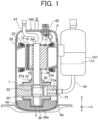
- FIG. 1 is a cross-sectional view illustrating a configuration of a compressor 100 according to a first embodiment.
- the compressor 100 is, for example, a rotary compressor.
- the compressor 100 is not limited to a rotary compressor, and may be another compressor such as a low-pressure compressor or a scroll compressor.
- the compressor 100 includes a compression mechanism 1, an electric motor 2, a crankshaft 3 as a rotation shaft, and a sealed container 4 as a container.
- the compression mechanism 1 sucks a refrigerant 110 from an accumulator 101 and compresses the refrigerant 110.
- the electric motor 2 drives the compression mechanism 1.
- the electric motor 2 is disposed on a downstream side with respect to the compression mechanism 1 in a direction in which the refrigerant 110 flows.
- the refrigerant 110 flows from a -z-axis side to a +z-axis side.
- a downstream side in the direction in which the refrigerant 110 flows is the +z-axis side
- an upstream side in the direction in which the refrigerant 110 flows is the -z-axis side.
- the refrigerant 110 includes ethylene-based fluorocarbon having a double bond of carbon. That is, the refrigerant 110 is a hydro fluoro olefin (HFO) refrigerant. Accordingly, since the refrigerant 110 includes ethylene-based fluorocarbon, a working pressure of the compressor 100 can be reduced. A global warming potential (GWP) of the refrigerant 110 is lower than a GWP of a hydro fluoro carbon (HFC) refrigerant. Thus, the greenhouse effect of the refrigerant 110 is smaller than the greenhouse effect of the HFC refrigerant. In addition, since the refrigerant 110 includes ethylene-based fluorocarbon, disproportionation of the refrigerant 110 can be prevented.
- HFO hydro fluoro olefin
- the refrigerant 110 is a refrigerant mixture in which ethylene-based fluorocarbon is mixed with another refrigerant.
- the refrigerant 110 includes R1123 (i.e., 1,1,2-trifluoroethylene) as ethylene-based fluorocarbon.
- the proportion of R1123 in the refrigerant 110 is preferably within the range from 40wt% to 60wt%, for example.
- the refrigerant 110 includes R32 (difluoromethane) as another refrigerant, for example. That is, in the first embodiment, the refrigerant 110 is a refrigerant mixture in which R1123 and R32 are mixed.
- R1123 is not limited to R32, and R1123 may be mixed with one or more refrigerants of R1234yf (i.e., 2,3,3,3-tetrafluoropropene), R1234ze(E) (i.e., trans-1,3,3,3-tetrafluoropropene), R1234ze(Z) (i.e., sis-1,3,3,3-tetrafluoropropene), R125 (1,1,1,2-pentafluoroethane), and R134a (i.e., 1,1,1,2-tetrafluoroethane).
- R1234yf i.e., 2,3,3,3-tetrafluoropropene
- R1234ze(E)
- the refrigerant 110 may include two or more types of ethylene-based fluorocarbon.
- the refrigerant 110 may include R1123 and another ethylene-based fluorocarbon.
- the refrigerant 110 may include one or more types of ethylene-based fluorocarbon of R1141 (i.e., fluoroethylene), R1132a (i.e., 1,1-diuoroethylene), R1132(E) (i.e., trans-1,2-difluoroethylene), and R1132(Z) (i.e., sis-1,2-difluoroethylene), as another ethylene-based fluorocarbon.
- the refrigerant 110 may include R290 (i.e., propane) composed of hydrocarbon, as well as ethylene-based fluorocarbon. That is, the refrigerant 110 may be a hydro carbon (HC) refrigerant.
- HC hydro carbon
- the crankshaft 3 couples the compression mechanism 1 and the electric motor 2 to each other.
- the crankshaft 3 includes a shaft body part 3a fixed to a rotor 10 of the electric motor 2 and an eccentric shaft part 3b fixed to a rolling piston 32 of the compression mechanism 1.
- a direction along a circumference of a circle about the crankshaft 3 will be referred to as a "circumferential direction,” a direction in which an axis (axis C shown in FIG. 2 described later) as a rotation center of the crankshaft 3 will be referred to as an "axial direction,” and a direction in which a line orthogonal to the axial direction and passing through the crankshaft 3 will be referred to as a "radial direction.”
- an xyz orthogonal coordinate system is shown in order to facilitate understanding of relationship among the drawings.
- the z axis is a coordinate axis parallel to the axis of the crankshaft 3.
- the y axis is a coordinate axis orthogonal to the z axis.
- the x axis is a coordinate axis orthogonal to both the y axis and the z axis.
- the sealed container 4 is a substantially cylindrical container, and contains the compression mechanism 1, the electric motor 2, the refrigerant 110, and refrigerating machine oil 40.
- the refrigerating machine oil 40 is lubricating oil for lubricating the compression mechanism 1, and is stored in a bottom portion 4a of the sealed container 4. That is, the bottom portion 4a of the sealed container 4 is an oil sump in which the refrigerating machine oil 40 is stored.
- the refrigerating machine oil 40 lubricates a sliding part of the compression mechanism 1 (e.g., a fitting part between the rolling piston 32 and the eccentric shaft part 3b of the crankshaft 3 shown in FIG. 2 described later).
- the refrigerating machine oil 40 flows through an oil supply passage (not shown) formed in the crankshaft 3 and lubricates the sliding part of the compression mechanism 1.
- the compressor 100 further includes a discharge pipe 41 and a terminal 42 attached to an upper portion of the sealed container 4.
- the discharge pipe 41 is connected to a refrigerant flow channel of the refrigeration cycle device.
- the discharge pipe 41 discharges the refrigerant 110 compressed by the compression mechanism 1 to the outside of the sealed container 4.
- the terminal 42 is connected to a driving device (not shown) disposed outside the compressor 100.
- the terminal 42 supplies a driving current to a coil 22 of a stator 20 of the electric motor 2 through a lead wire 44. Accordingly, magnetic flux flows in the coil 22 and consequently the rotor 10 rotates.
- FIG. 2 is a cross-sectional view illustrating a configuration of the compression mechanism 1 shown in FIG. 1 .
- the compression mechanism 1 includes a cylinder 31, the rolling piston 32, a vane 33, an upper bearing 34, and a lower bearing 35.
- the cylinder 31 includes a suction port 31a, a cylinder chamber 31b, and a vane groove 31c.
- the suction port 31a is connected to the accumulator 101 through a suction pipe 43.
- the suction port 31a is a passage in which the refrigerant 110 sucked from the accumulator 101 flows, and communicates with the cylinder chamber 31b.
- the cylinder chamber 31b is cylindrical space about the axis C.
- the cylinder chamber 31b houses the eccentric shaft part 3b of the crankshaft 3, the rolling piston 32, and the vane 33.
- the rolling piston 32 has a ring shape.
- the rolling piston 32 is fixed to the eccentric shaft part 3b of the crankshaft 3.
- the vane groove 31c communicates with the cylinder chamber 31b.
- the vane 33 is attached to the vane groove 31c.
- a back-pressure chamber 31d is provided in an end portion of the vane groove 31c.
- the vane 33 is pressed by a spring (not shown) disposed in the back-pressure chamber 31d toward the axis C to be thereby brought into contact with an outer peripheral surface of the rolling piston 32.
- the vane 33 divides space 36 surrounded by an inner peripheral surface of the cylinder chamber 31b, the outer peripheral surface of the rolling piston 32, the upper bearing 34, and the lower bearing 35 into a suction-side working chamber (hereinafter referred to as a "suction chamber”) 36a and a compression-side working chamber (hereinafter referred to as a “compression chamber”) 36b.
- the suction chamber 36a communicates with the suction port 31a.
- the vane 33 While the rolling piston 32 eccentrically rotates, the vane 33 reciprocates in the y-axis direction in the vane groove 31c.
- the vane 33 has a plate shape, for example.
- the rolling piston 32 and the vane 33 are separate components, but the rolling piston 32 may be integrated with the vane 33.
- the upper bearing 34 closes an end portion of the cylinder chamber 31b on the +z-axis side.
- the lower bearing 35 closes an end portion of the cylinder chamber 31b on the -z-axis side.
- the upper bearing 34 and the lower bearing 35 are fixed to the cylinder 31 by fastening members (e.g., bolts).
- Each of the upper bearing 34 and the lower bearing 35 has a discharge port from which the compressed refrigerant 110 (see FIG. 1 ) is discharged to the outside of the cylinder chamber 31b.
- the discharge port of each of the upper bearing 34 and the lower bearing 35 communicates with the compression chamber 36b of the cylinder chamber 31b.
- the discharge port is provided with a discharge valve (not shown). When the pressure of the refrigerant 110 compressed in the compression chamber 36b increases to a predetermined pressure or more, the discharge valve opens and allows the high-temperature and high-pressure refrigerant 110 to be discharged to inner space of the sealed container 4.
- the lower bearing 35 may not have a discharge port.
- An upper discharge muffler 37 is attached to the upper bearing 34 with a fastening member (e.g., a bolt).
- a muffler chamber 37a is disposed between the upper bearing 34 and the upper discharge muffler 37. Accordingly, the refrigerant 110 discharged from the discharge port of the upper bearing 34 is diffused in the muffler chamber 37a, and thus, occurrence of discharge noise of the refrigerant 110 discharged from the discharge port of the upper bearing 34 can be suppressed.
- a lower discharge muffler 38 is attached to the lower bearing 35 with a fastening member (e.g., a bolt).
- a muffler chamber 38a is disposed between the lower bearing 35 and the lower discharge muffler 38. Accordingly, the refrigerant 110 discharged from the discharge port of the lower bearing 35 is diffused in the muffler chamber 38a, and thus, occurrence of discharge noise of the refrigerant 110 discharged from the lower bearing 35 can be suppressed.
- a discharge muffler may be attached to the bearing having the discharge port.
- a driving current is supplied from the terminal 42 to the electric motor 2 and consequently the rotor 10 of the electric motor 2 rotates.
- the crankshaft 3 rotates accordingly.
- the rolling piston 32 and the eccentric shaft part 3b rotate about an axis eccentric from the axis C in a direction indicated by arrow A in FIG. 2 . Accordingly, the low-pressure refrigerant 110 is sucked into the suction chamber 36a.
- the refrigerant 110 sucked in the suction chamber 36a is compressed by rotation of the rolling piston 32.
- the vane 33 reciprocates in the vane groove 31c to cause the refrigerant 110 sucked in the suction chamber 36a to move to the compression chamber 36b to be compressed.
- the refrigerant 110 compressed in the compression chamber 36b changes to a high-temperature and high-pressure refrigerant gas and is discharged from one of the upper discharge muffler 37 or the lower discharge muffler 38.
- the refrigerating machine oil 40 is dissolved in the refrigerant 110 compressed by the compression mechanism 1.
- the refrigerating machine oil 40 flows in flow channel 15 (see FIG. 1 ) as an air opening formed in the rotor 10 of the electric motor 2, through the oil supply passage (not shown) formed in the crankshaft 3. At this time, the refrigerant 110 and the refrigerating machine oil 40 are separated in the flow channel 15 by a centrifugal force exerted during rotation of the rotor 10.
- the refrigerating machine oil 40 having a larger specific gravity than the refrigerant 110 flows at the outer side in the radial direction in the flow channel 15, and the refrigerant 110 flows at the inner side in the radial direction in the flow channel 15 and consequently the refrigerant 110 and the refrigerating machine oil 40 are separated.
- the refrigerating machine oil 40 separated from the refrigerant 110 cools the rotor core 11 and a permanent magnet 12 of the rotor 10.
- the refrigerant 110 is discharged to the outside of the sealed container 4 through the discharge pipe 41, and flows in a refrigerant flow channel (e.g., refrigerant flow channel 310 shown in FIGS. 12 and 13 described later) of the refrigeration cycle device.
- FIG. 3 is a cross-sectional view illustrating the configuration of the electric motor 2 according to the first embodiment.
- the electric motor 2 includes the rotor 10 and the stator 20.
- the rotor 10 is disposed at the inner side of the stator 20. That is, the electric motor 2 according to the first embodiment is an inner-rotor electric motor.
- An air gap E is present between the rotor 10 and the stator 20.
- the air gap E is a gap defined within the range from 0.3 mm to 1.0 mm, for example.
- the stator 20 includes a stator core 21 and the coil 22 wound around the stator core 21.
- the stator core 21 is fixed to the sealed container 4 illustrated in FIG. 1 .
- the stator core 21 is fixed to the inner wall of the sealed container 4 by a method such as press fitting, shrink fitting, or welding, for example.
- the coil 22 is wound around the stator core 21 with an insulator 23 interposed therebetween.
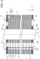
- FIG. 4 is a cross-sectional view illustrating a configuration of the rotor 10 shown in FIG. 1 .
- FIG. 5 is a cross-sectional view illustrating a portion of the configuration of the rotor 10 shown in FIG. 3 .
- the rotor 10 includes a rotor core 11, a permanent magnet 12a as a first permanent magnet, and a permanent magnet 12b as a second permanent magnet.
- the permanent magnets 12a and 12b are inserted in magnet insertion holes 11b of the rotor core 11.
- the permanent magnet 12a and the permanent magnet 12b will be collectively referred to as "permanent magnets 12."
- the permanent magnets 12 are omitted from FIG. 4 .
- the rotor core 11 includes a plurality of electromagnetic steel sheets 13 as a plurality of steel sheets laminated in a z-axis direction.
- the plurality of electromagnetic steel sheets 13 are laminated with a gap D as a first gap in between.
- the rotor core 11 includes non-oriented electromagnetic steel sheets as the electromagnetic steel sheets 13.
- a thickness t 1 of each of the electromagnetic steel sheet 13 is a predetermined thickness within the range from 0.2 mm to 0.7 mm, for example. In the first embodiment, the thickness t 1 of each electromagnetic steel sheet 13 is, for example, 0.35 mm.
- the rotor core 11 may include other magnetic steel sheets, instead of the electromagnetic steel sheets 13.
- the plurality of electromagnetic steel sheets 13 are fixed to one another by swaging, and thus the rotor core 11 is formed.
- the rotor core 11 includes a swaging portion 14.
- the swaging portion 14 includes a swaging projection 14a and a swaging recess 14b.
- the swaging projection 14a is a projection projecting toward another adjacent electromagnetic steel sheet 13.
- the swaging recess 14b is a recess in which the swaging projection 14a is fitted.
- the swaging projection 14a is fitted in the swaging recess 14b of another adjacent electromagnetic steel sheet 13 and consequently two adjacent electromagnetic steel sheets 13 are fastened.
- the swaging projection 14a is a V-shaped projection.
- the swaging projection is a cylindrical projection
- a fastening force for fastening two adjacent electromagnetic steel sheets 13 is enhanced.
- the length of the swaging projection 14a in the z-axis direction is larger than the thickness t 1 of each electromagnetic steel sheet 13.
- a spacing t 2 of the gap D is smaller than the thickness t 1 of each electromagnetic steel sheet 13.
- the spacing t 2 is, for example, equal to or less than 1/10 of the thickness t 1 of each electromagnetic steel sheet 13.
- the spacing t 2 is 10 ⁇ m or less.
- the spacing t 2 has a predetermined dimension within the range from 1 ⁇ m to 5 um.
- the swaging projection 14a since the swaging projection 14a has the V-shaped projection as described above, dimensional accuracy of the spacing t 2 is sufficiently obtained as compared to the configuration in which the swaging projection is a cylindrical projection.
- the rotor core 11 includes a shaft insertion hole 11a as a shaft insertion hole and the plurality of magnet insertion holes 11b.
- the crankshaft 3 (see FIG. 4 ) is fixed to the shaft insertion hole 11a.
- the crankshaft 3 is fixed to the shaft insertion hole 11a by a method such as press fitting, shrink fitting, or welding, for example.
- the plurality of magnet insertion holes 11b are spaced from one another in a circumferential direction R with a spacing.
- the shape of each magnet insertion hole 11b when seen in the z-axis direction is a V shape projecting radially inward.
- the shape of each magnet insertion hole 11b when seen in the z-axis direction may be an arc shape projecting radially inward or outward or a bathtub shape projecting radially outward.
- the shape of each magnet insertion hole 11b when seen in the z-axis direction may be a rectangle.
- the permanent magnet 12a and the permanent magnet 12b are embedded in the magnet insertion holes 11b.
- the structure of the rotor 10 is an interior permanent magnet (IPM) structure.
- the permanent magnet 12a and the permanent magnet 12b are disposed with a gap S1 as a second gap in between in the magnet insertion holes 11b.
- the rotor core 11 has six magnet insertion holes 11b, for example. Accordingly, in the first embodiment, the number of poles of the electric motor 2 is six.
- the number of poles of the electric motor 2 is not limited to six, and only needs to be two or more.
- the permanent magnet 12 is, for example, a plate-shaped magnet.
- the shape of the permanent magnet 12 when seen in the z-axis direction is a rectangle.
- the permanent magnet 12 is not limited to a plate-shaped magnet, and may be a magnet having a semicylindrical curved surface.
- the thickness of the permanent magnet 12 in the lateral direction is smaller than the thickness of each magnet insertion hole 11b in the lateral direction.
- a gap S2 as a third gap is present between the permanent magnet 12 and the magnet insertion hole 11b.
- the gap S2 has a predetermined dimension within the range from 0.1 mm to 0.2 mm, for example.
- the gap S2 is present between the magnet insertion hole 11b and a radially outward surface 12c of the permanent magnet 12a and between the magnet insertion hole 11b and a radially outward surface 12d of the permanent magnet 12b. That is, the gap S2 is located radially outward of the permanent magnets 12a and 12b. The gap S2 may be located radially inward of the permanent magnets 12a and 12b.
- the permanent magnet 12 is, for example, a rare earth magnet.
- the permanent magnet 12 is a rare earth magnet including neodymium (Nd), iron (Fe), and boron (B).
- the permanent magnet 12 may include none of dysprosium (Dy) and terbium (Tr).
- Dy and Tr are rare earth metals, and thus, expensive.
- the Dy content and the Tr content in the permanent magnets 12 are 0 wt.%, and thus, costs for the permanent magnets 12 can be reduced.
- the permanent magnets 12 may include less than 1.0 wt.% of Dy or less than 1.0 wt.% of Tr.
- the permanent magnets 12 may include both less than 1.0 wt.% of Dy and less than 1.0 wt.% of Tr.
- the permanent magnet 12 is not limited to a rare earth magnet, and may be another permanent magnet such as a ferrite magnet.
- a flux barrier 11c is present between the magnet insertion hole 11b and the end portion of the permanent magnet 12 in the circumferential direction R. Since a portion between the flux barrier 11c and an outer periphery 11j of the rotor core 11 is a thin portion, leakage flux between adjacent magnetic poles are suppressed.
- the flux barrier 11c communicates with the gap S2.
- the refrigerant 110 and the refrigerating machine oil 40 flow in the flux barrier 11c.
- the rotor core 11 further includes the plurality of flow channels 15.
- the refrigerant 110 compressed by the compression mechanism 1 and the refrigerating machine oil 40 dissolved in the refrigerant 110 flow in each of the flow channels 15 of the plurality of flow channels 15.
- the rotor core 11 includes, for example, six flow channels 15. That is, in the first embodiment, the number of the flow channels 15 is equal to the number of the magnet insertion holes 11b. The number of the flow channels 15 may be different from the number of the magnet insertion holes 11b.
- the flow channels 15 are formed radially inward of the magnet insertion holes 11b.
- the flow channels 15 are through holes penetrating the rotor core 11 in the z-axis direction.
- the opening of the flow channel 15 is, for example, circular.
- the opening of the flow channel 15 is not limited to a circular shape, and may have another shape such as an oval, or may have any shape formed by combining a curve and a straight line.
- FIG. 6A is an enlarged cross-sectional view illustrating a portion of the configuration of the rotor 10 shown in FIG. 5 .
- FIG. 6B is a cross-sectional view of a portion of the configuration of the rotor 10 shown in FIG. 6A taken along line B6-B6.
- the rotor core 11 includes a guide part 16 as an oil introduction part for guiding the refrigerating machine oil 40 (see FIG. 1 ) to the gap D.
- the guide part 16 has a guide structure for guiding the refrigerating machine oil 40 flowing in the flow channels 15 together with the refrigerant 110 to the gap D when the rotor 10 rotates.
- the refrigerating machine oil 40 flows along a path indicated by arrows in FIG. 6B .
- the refrigerating machine oil 40 guided in the gap D flows from the inside to the outside in the radial direction in the gap D under the influence of a centrifugal force. Accordingly, the refrigerating machine oil 40 flows in the gap S1 (see FIG. 5 ) in the magnet insertion hole 11b.
- the refrigerating machine oil 40 flows in the gap D and then flows toward the bottom portion 4a of the sealed container 4 (see FIG. 1 ) under the influence of the gravity.
- the refrigerating machine oil 40 flowing in the flow channels 15 is guided by the guide part 16 to the gap D and consequently the refrigerating machine oil 40 flows in the gap D and passes through the gap S1, and accordingly, the permanent magnets 12 are easily cooled.
- the refrigerating machine oil 40 that has flowed in the flow channels 15 can easily return to the bottom portion 4a of the sealed container 4 (see FIG. 1 ) through the gap D. Accordingly, the compression mechanism 1 is easily lubricated by the refrigerating machine oil 40, and thus poor lubrication in the compressor 100 can be prevented.
- the refrigerant 110 is a refrigerant including ethylene-based fluorocarbon (R1123 in the first embodiment) described above
- the flow rate of the refrigerant 110 discharged from the compressor 100 decreases disadvantageously.
- the flow rate of the refrigerant 110 flowing in the flow channels 15 increases, the flow velocity of the refrigerant 110 increases, and thus, the refrigerating machine oil 40 is not easily separated from the refrigerant 110.
- the guide part 16 since the rotor core 11 includes the guide part 16, even in the case where the refrigerant 110 includes ethylene-based fluorocarbon, the guide part 16 easily guides the refrigerating machine oil 40 to the gap D. Accordingly, the refrigerating machine oil 40 flowing in the flow channels 15 is easily separated from the refrigerant 110.
- the guide part 16 is provided in the flow channel 15.
- the guide part 16 has a radially inward surface 17 defining the flow channel 15.
- the radially inward surface 17 includes a vertical portion 171 and a slope portion 172 as a first slope portion.
- the vertical portion 171 is a plane of the radially inward surface 17 extending in parallel with the z-axis direction.
- the slope portion 172 is closer to the +z-axis side than the vertical portion 171.
- the slope portion 172 is a slope that inclines in a direction away from the axis C (see FIG. 4 ) of the rotor 10 as approaching an end surface 13d at the +z-axis side that is an end surface of the electromagnetic steel sheets 13 in the z-axis direction.
- the refrigerating machine oil 40 flows along the vertical portion 171 and the slope portion 172 in the flow channel 15 to be thereby guided to a portion of the gap D radially outside the flow channel 15 (i.e., in a direction toward the magnet insertion hole 11b).
- the slope portion 172 is a flat surface, but may be a curved surface.
- the guide part 16 includes the slope portion 172 in the radially inward surface 17 defining the flow channel 15.
- the refrigerating machine oil 40 flowing in the flow channel 15 is easily guided to the gap D through the slope portion 172.
- the gap S1 faces the guide part 16 in the radial direction. Accordingly, the refrigerating machine oil 40 guided to the gap D by the guide part 16 easily flows in the gap S1. Thus, the permanent magnets 12a and 12b are easily cooled by the refrigerating machine oil 40.
- the area A1 is larger than the area A2.
- the area A1 is, for example, equal to or larger than 10 times as large as the area A2. Since the guide part 16 is provided in the flow channel 15, as the area A1 is larger than the area A2, the length of the guide part 16 in the circumferential direction R increases. Accordingly, the refrigerating machine oil 40 is easily separated from the refrigerant 110 flowing in the flow channels 15.
- the spacing t 3 is larger than the spacing t 2 (see FIG. 4 ) of the gap D. That is, the spacing t 3 and the spacing t 2 satisfy Equation (1): t 3 > t 2
- the refrigerating machine oil 40 guided from the flow channel 15 to the gap D easily flows in the gap S2.
- the refrigerating machine oil 40 flows along the radially outward surfaces 12c and 12d of the permanent magnets 12a and 12b and consequently the permanent magnets 12a and 12b can be more easily cooled.
- the flow channel 15 is formed between the magnet insertion hole 11b and the shaft insertion hole 11a in the rotor core 11. Specifically, the flow channel 15 is disposed closer to the magnet insertion hole 11b than the shaft insertion hole 11a. Accordingly, a thin portion 11g is formed between the magnet insertion hole 11b and the flow channel 15. The thin portion 11g extends in the circumferential direction R. Supposing the thickness of the thin portion 11g is W 1 , the thickness W 1 is uniform in the circumferential direction R. The thickness W 1 is equal to or larger than the thickness t 1 of each electromagnetic steel sheet 13. Accordingly, a sufficient strength of the thin portion 11g is obtained.
- the length of a portion of the gap D between the shaft insertion hole 11a and the flow channel 15 increases, and thus, a passage in which the refrigerant 110 flows in the gap D can be sufficiently obtained.
- a sufficient thickness of the bridge portion 11h as an iron core portion around the shaft insertion hole 11a is obtained, when the crankshaft 3 is fixed to the shaft insertion hole 11a, a sufficient strength of the rotor core 11 is obtained.
- the rotor 10 includes an upper end plate 51 as a first end plate and a lower end plate 52 as a second end plate.
- the upper end plate 51 is disposed on an end surface 11m at the +z-axis side as a first end surface of the rotor core 11.
- the lower end plate 52 is disposed on an end surface 11n at the -z-axis side as a second end surface of the rotor core 11.
- the rotor 10 may be implemented when the rotor 10 includes only one of the upper end plate 51 and the lower end plate 52.
- FIG. 7A is a plan view illustrating a configuration of the upper end plate 51.
- the upper end plate 51 is an annular plate about the axis C.
- the upper end plate 51 includes a shaft insertion hole 51a in which the crankshaft 3 is inserted and through holes 51b as first through holes communicating with the flow channels 15 of the rotor core 11.
- the refrigerant 110 that has passed through the flow channels 15 flows in the through holes 51b. Accordingly, the refrigerant 110 that has flowed in the flow channels 15 is easily guided to the discharge pipe 41 through the through holes 51b.
- the upper end plate 51 covers the magnet insertion holes 11b. In other words, the upper end plate 51 closes the magnet insertion holes 11b. Accordingly, it is possible to prevent the refrigerating machine oil 40 that has flowed in the magnet insertion holes 11b from flowing to the outside of the compressor 100 through the discharge pipe 41.
- FIG. 7B is a plan view illustrating a configuration of the lower end plate 52.
- the lower end plate 52 is an annular plate about the axis C.
- the lower end plate 52 includes a shaft insertion hole 52a in which the crankshaft 3 is inserted and through holes 52b as second through holes communicating with the flow channels 15.
- the lower end plate 52 further includes a slits 52c as first slits communicating with the gaps S1 of the rotor core 11 and slits 52d as second slits communicating with the flux barriers 11c.
- the refrigerating machine oil 40 flows in the through holes 52b and the slits 52c and 52d. Since the oil sump (i.e., the bottom portion 4a of the sealed container 4) is provided at the -z-axis side of the lower end plate 52, the refrigerating machine oil 40 flows in the through holes 52b and the slits 52c and 52d to be thereby returned to the oil sump.
- the rotor core 11 of the electric motor 2 that drives the compression mechanism 1 includes the guide part 16 that guides the refrigerating machine oil 40 flowing in the flow channels 15 to the gap D when the rotor 10 rotates. Accordingly, the refrigerating machine oil 40 easily flows in the gap D between the plurality of electromagnetic steel sheets 13 constituting the rotor core 11, and thus the permanent magnets 12 can be easily cooled. In addition, since the refrigerating machine oil 40 easily flows in the gap D, the refrigerating machine oil 40 can easily return to the bottom portion 4a of the sealed container 4 as the oil sump. Accordingly, the compression mechanism 1 is easily lubricated by the refrigerating machine oil 40 and consequently poor lubrication in the compressor 100 can be prevented.
- the stroke volume of the compressor 100 decreases disadvantageously, and thus, the flow rate of the refrigerant 110 flowing in the flow channels 15 needs to be increased.
- the flow rate of the refrigerant 110 flowing in the refrigerant 110 increases, the flow velocity of the refrigerant 110 increases, and thus, the refrigerant 110 and the refrigerating machine oil 40 are not easily separated from each other.
- the guide part 16 since the rotor core 11 includes the guide part 16 described above, even if the refrigerant 110 is a refrigerant including ethylene-based fluorocarbon, the guide part 16 makes it easier to separate the refrigerating machine oil 40 from the refrigerant 110 and to guide to the gap D.
- the guide part 16 has the radially inward surface 17 defining the flow channel 15, and the radially inward surface 17 includes the slope portion 172 that inclines in a direction away from the axis C as approaching the end surface 13d of the electromagnetic steel sheets 13 at the +z-axis side. Accordingly, the refrigerating machine oil 40 flowing in the flow channels 15 can be easily guided to the gap D through the slope portion 172 when the rotor 10 rotates.
- the spacing t 3 of the gap S2 between the magnet insertion hole 11b and the surfaces 12c and 12d of the permanent magnet 12 facing in the radial direction is larger than the spacing t 2 of the gap D. Accordingly, the refrigerating machine oil 40 guided from the flow channels 15 to the gap D easily flows in the gap S2. Consequently, the permanent magnet 12 can be easily cooled by the refrigerating machine oil 40.
- the gap S2 is located radially outward from the permanent magnet 12. Since the refrigerating machine oil 40 guided to the gap D is subjected to the effect of a centrifugal force when the rotor 10 rotates, the refrigerating machine oil 40 easily flows in the gap D in a direction away from the axis C, that is, from the inside to the outside of the rotor core 11 in the radial direction. Thus, the gap S2 is present radially outward from the permanent magnets 12 and consequently the refrigerating machine oil 40 can easily flow to the gap S2 through the gap D. Accordingly, the permanent magnets 12 can be easily cooled by the refrigerating machine oil 40.
- the rotor 10 further includes the upper end plate 51 disposed at the end surface 11m of the rotor core 11 on a downstream side in the direction in which the refrigerant 110 flows, and the upper end plate 51 covers the magnet insertion holes 11b. Accordingly, it is possible to prevent the refrigerating machine oil 40 guided to the gap D by the guide part 16 from flowing to the outside of the compressor 100 through the discharge pipe 41 after having flowed from the magnet insertion holes 11b.
- the upper end plate 51 has the through hole 51b which communicates with the flow channels 15 and through which the refrigerant 110 flows. Accordingly, the refrigerant 110 that has flowed in the flow channels 15 easily flows to the outside of the compressor 100 through the discharge pipe 41 after having flowed from the through hole 51b.
- the rotor 10 further includes the lower end plate 52 disposed at the end surface 11n of the rotor core 11 at the upstream side in the direction in which the refrigerant 110 flows.
- the lower end plate 52 has the through hole 52b which communicates with the flow channels 15 and through which the refrigerating machine oil 40 flows. Accordingly, when the refrigerating machine oil 40 flowing in the flow channels 15 is subjected to the effect of the gravity, the refrigerating machine oil 40 easily returns to the bottom portion 4a of the sealed container 4 through the through hole 52b.
- the compression mechanism 1 is easily lubricated by the refrigerating machine oil 40 and consequently poor lubrication in the compressor 100 can be prevented.
- the lower end plate 52 further includes the slit 52c which communicates with the gap S1 and in which the refrigerating machine oil 40 flows. Accordingly, when the refrigerating machine oil 40 flowing in the gap S1 is subjected to the effect of the gravity, the refrigerating machine oil 40 easily returns to the bottom portion 4a of the sealed container 4 through the slit 52c. Thus, the compression mechanism 1 is easily lubricated by the refrigerating machine oil 40 and consequently poor lubrication in the compressor 100 can be prevented.
- the rotor core 11 further includes the flux barrier 11c present between the magnet insertion hole 11b and the end portion of the permanent magnet 12 in the circumferential direction.
- the lower end plate 52 further includes the slit 52d which communicates with the flux barrier 11c and in which the refrigerating machine oil 40 flows. Accordingly, when the refrigerating machine oil 40 flowing in the flux barrier 11c is subjected to the effect of the gravity, the refrigerating machine oil 40 can easily return to the bottom portion 4a of the sealed container 4 through the slit 52d.
- the compression mechanism 1 is easily lubricated by the refrigerating machine oil 40 and consequently poor lubrication in the compressor 100 can be prevented.
- the rotor core 11 includes the shaft insertion hole 11a in which the crankshaft 3 is inserted.
- the thickness W 1 of the thin portion 11g as an iron core portion between the magnet insertion hole 11b and the flow channel 15 in the rotor core 11 is smaller than the thickness W 2 of the bridge portion 11h as an iron core portion between the flow channel 15 and the shaft insertion hole 11a in the rotor core 11. Accordingly, the length of a portion of the gap D between the shaft insertion hole 11a and the flow channel 15 is large, and thus, a sufficient passage in which the refrigerant 110 flows in the gap D can be obtained.
- a sufficient thickness of the bridge portion 11h is obtained, strength of the rotor 10 can be sufficiently ensured when the crankshaft 3 is fixed to the shaft insertion hole 11a.
- FIG. 8 is a cross-sectional view illustrating a configuration of a rotor 10a of an electric motor of a compressor according to a first variation of the first embodiment.
- the same reference characters as those in FIG. 4 designate the same or corresponding components as those illustrated in FIG. 4 .
- the compressor according to the first variation of the first embodiment is different from the compressor 100 according to the first embodiment in the configuration of a guide part 16a. In other respects, the compressor according to the first variation of the first embodiment is the same as the compressor 100 according to the first embodiment. Thus, the following description will be made with reference to FIG. 1 .
- the rotor 10a includes a rotor core 111.
- the rotor core 111 includes a plurality of electromagnetic steel sheets 13a laminated in the z-axis direction with a gap D in between.
- the rotor core 111 includes a flow channel 15 and a guide part 16a.
- the guide part 16a guides refrigerating machine oil 40 (see FIG. 1 ) flowing in the flow channels 15 to a gap D when the rotor 10a rotates.
- the guide part 16a includes a radially inward surface 17a defining the flow channel 15.
- the radially inward surface 17a includes a vertical portion 171 and a slope portion 173 as a second slope portion.
- the slope portion 173 is disposed closer to the -z-axis side than the vertical portion 171.
- the slope portion 173 is a slope that inclines in a direction away from an axis C as approaching an end surface 13e at the -z-axis side as another end surface of the electromagnetic steel sheets 13a in the z-axis direction.
- the refrigerating machine oil 40 flowing in the flow channels 15 is guided to the gap D through the slope portion 173. Accordingly, the refrigerating machine oil 40 easily flows in the gap D, and thus, the permanent magnet 12 is easily cooled. Since the refrigerating machine oil 40 easily flows in the gap D, the refrigerating machine oil 40 can easily return to a bottom portion 4a of a sealed container 4 (see FIG. 1 ). Thus, a compression mechanism 1 is easily lubricated by the refrigerating machine oil 40 and consequently poor lubrication in the compressor 100 can be prevented.
- the radially inward surface 17a defining the flow channel 15 in the guide part 16a includes the slope portion 173 that inclines in the direction away from the axis C as approaching the end surface 13e of the electromagnetic steel sheets 13a at the -z-axis side. Accordingly, the refrigerating machine oil 40 easily flows in the gap D between the plurality of electromagnetic steel sheets 13a constituting the rotor core 111 and consequently the permanent magnets 12 can be easily cooled. Since the refrigerating machine oil 40 easily flows in the gap D, the refrigerating machine oil 40 can easily return to the bottom portion 4a of the sealed container 4. Thus, the compression mechanism 1 is easily lubricated by the refrigerating machine oil 40 and consequently poor lubrication in the compressor can be prevented.
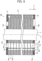
- FIG. 9 is a cross-sectional view illustrating a configuration of a rotor 10b of an electric motor of a compressor according to a second variation of the first embodiment.
- the same reference characters as those in FIGS. 4 and 8 designate the same or corresponding components as those illustrated in FIGS. 4 and 8 .
- the compressor according to the second variation of the first embodiment is different from the compressor 100 according to the first embodiment in the configuration of a guide part 16b.
- the compressor according to the second variation of the first embodiment is the same as the compressor 100 according to the first embodiment.
- FIG. 1 the following description will be made with reference to FIG. 1 .
- the rotor 10b includes a rotor core 112.
- the rotor core 112 includes a plurality of electromagnetic steel sheets 13b laminated in the z-axis direction with a gap D in between.
- the rotor core 112 includes a flow channel 15 and a guide part 16b.
- the guide part 16b guides the refrigerating machine oil 40 flowing in the flow channels 15 to a gap D when the rotor 10b rotates.
- the guide part 16b includes a radially inward surface 17b defining the flow channel 15.
- the radially inward surface 17b includes a slope portion 172 as a first slope portion, a slope portion 173 as a second slope portion, and a coupling portion 174 coupling the slope portion 172 and the slope portion 173 to each other. That is, in the second variation of the first embodiment, the guide part 16b includes two slope portions 172 and 173. Accordingly, refrigerating machine oil 40 flowing in the flow channels 15 is guided to the gap D through the slope portions 172 and 173. Accordingly, the refrigerating machine oil 40 more easily flows in the gap D, and thus, the permanent magnets 12 are more easily cooled.
- the refrigerating machine oil 40 Since the refrigerating machine oil 40 is guided to the gap D through the slope portions 172 and 173, the refrigerating machine oil 40 can easily return to the bottom portion 4a of the sealed container' 4. Thus, the compression mechanism 1 is easily lubricated by the refrigerating machine oil 40 and consequently poor lubrication in the compressor can be prevented.
- the radially inward surface 17b defining the flow channel 15 in the guide part 16b includes the slope portion 172 and the slope portion 173.
- the slope portion 172 inclines in a direction away from the axis C as approaching the end surface 13d of the electromagnetic steel sheets 13b at the +z-axis side.
- the slope portion 173 inclines in a direction away from the axis C as approaching the end surface 13e of the electromagnetic steel sheets 13b at the -z-axis side. Accordingly, the refrigerating machine oil 40 more easily flows in the gap D between the plurality of electromagnetic steel sheets 13b constituting the rotor core 112 and consequently the permanent magnets 12 can be easily cooled.
- the refrigerating machine oil 40 since the refrigerating machine oil 40 easily flows in the gap D, the refrigerating machine oil 40 can easily return to the bottom portion 4a of the sealed container 4 as an oil sump. Thus, the compression mechanism 1 is easily lubricated by the refrigerating machine oil 40 and consequently poor lubrication in the compressor can be prevented.
- FIG. 10 is a cross-sectional view illustrating a configuration of a rotor 210 of an electric motor of a compressor according to a second embodiment.
- the same reference characters as those in FIG. 4 designate the same or corresponding components as those illustrated in FIG. 4 .
- the compressor according to the second embodiment is different from the compressor 100 according to the first embodiment in the configuration of a guide part 216. In other respects, the compressor according to the second embodiment is the same as the compressor 100 according to the first embodiment. Thus, the following description will be made with reference to FIG. 1 .
- the rotor 210 includes a rotor core 211.
- the rotor core 211 includes a plurality of electromagnetic steel sheets 213 laminated in the z-axis direction with a gap D in between.
- the rotor core 211 includes flow channel 15 and the guide part 216.
- the guide part 216 guides refrigerating machine oil 40 flowing in the flow channels 15 to the gap D when the rotor 210 rotates.
- the guide part 216 includes a radially inward surface 17 defining the flow channel 15 and a radially outward surface 18 defining the flow channel 15.
- the radially outward surface 18 of the guide part 216 includes a vertical portion 181 and a slope portion 182 as a third slope portion.
- the vertical portion 181 is a flat surface extending in parallel with the z-axis direction in the radially outward surface 18.
- the slope portion 182 is closer to the +z-axis side than the vertical portion 181.
- the slope portion 182 is a slope that inclines in a direction toward an axis C as approaching an end surface 13d of the electromagnetic steel sheets 213 at the +z-axis side.
- the slope portion 182 may be disposed closer to the -z-axis side than the vertical portion 181.
- the slope portion of the radially outward surface 18 may be a slope that inclines in a direction toward the axis C as approaching the end surface 13e of the electromagnetic steel sheets 213 at the -z-axis side.
- the radially outward surface 18 may include a plurality of slope portions at both sides of the vertical portion 181 in the z-axis direction.
- the slope portion 182 is a flat surface, but may be a curved surface.
- the refrigerating machine oil 40 flowing in the flow channels 15 is guided to the gap D through the slope portion 182 as well as the slope portion 172, when the rotor 210 rotates. Accordingly, the refrigerating machine oil 40 flowing in the flow channels 15 easily flows in the gap D. Thus, the permanent magnets 12 are easily cooled. In addition, the refrigerating machine oil 40 is easily guided to the gap D through the slope portions 172 and 182 and consequently the refrigerating machine oil 40 can easily return to the bottom portion 4a of the sealed container 4. Thus, the compression mechanism 1 is easily lubricated by the refrigerating machine oil 40 and consequently poor lubrication in the compressor can be prevented.
- the guide part 216 further includes the radially outward surface 18 defining the flow channel 15.
- the radially outward surface 18 includes the slope portion 182 that inclines in the direction toward the axis C as approaching the end surface 13d of the electromagnetic steel sheets 213. Accordingly, the refrigerating machine oil 40 easily flows in the gaps D between the plurality of electromagnetic steel sheets 213 constituting the rotor core 211 and consequently the permanent magnets 12 can be easily cooled. In addition, since the refrigerating machine oil 40 easily flows in the gaps D, the refrigerating machine oil 40 can easily return to the bottom portion 4a of the sealed container 4 as an oil sump. Thus, the compression mechanism 1 is easily lubricated by the refrigerating machine oil 40 and consequently poor lubrication in the compressor can be prevented.
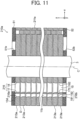
- FIG. 11 is a cross-sectional view illustrating a configuration of a rotor 210a of an electric motor of a compressor according to a first variation of the second embodiment.
- the same reference characters as those in FIG. 10 designate the same or corresponding components as those illustrated in FIG. 10 .
- the compressor according to the first variation of the second embodiment is different from the compressor according to the second embodiment in that the rotor 210a further includes the guide part 216a as a second guide part.
- the compressor according to the first variation of the second embodiment is the same as the compressor according to the second embodiment.
- the rotor 210a includes a rotor core 211a.
- the rotor core 211a includes a plurality of electromagnetic steel sheets 213a laminated in the z-axis direction with a gap D in between.
- the rotor core 211a includes flow channel 15, a guide part 216 as a first guide part, and a guide part 216a as a second guide part.
- the guide part 216a is included in the magnet insertion hole 11b.
- the guide part that guides the refrigerating machine oil 40 to the gap D when the rotor 210a rotates is included in the flow channel 15 and the magnet insertion hole 11b.
- the guide part 216a guides the refrigerating machine oil 40 flowing in the magnet insertion holes 11b to the gap D when the rotor 210a rotates.
- the refrigerating machine oil 40 that has flowed in the magnet insertion holes 11b is guided to a portion of the gap D radially outward from the magnet insertion holes 11b, and thus, easily returns to the bottom portion 4a of the sealed container 4.
- the compression mechanism 1 is easily lubricated by the refrigerating machine oil 40 and consequently poor lubrication in the compressor can be prevented.
- the guide part 216a includes the radially inward surface 216b defining the magnet insertion hole 11b.
- the radially inward surface 216b includes a vertical portion 191 and a slope portion 192.
- the vertical portion 191 is a plane extending in parallel with the z-axis direction in the radially inward surface 216b.
- the slope portion 192 is disposed closer to the +z-axis side than the vertical portion 191.
- the slope portion 192 is a slope that inclines in a direction away from an axis C (see FIG. 4 ) of the rotor 10 as approaching an end surface 13d of the electromagnetic steel sheets 213 at the +z-axis side.
- the slope portion 192 may be disposed closer to the -z-axis side than the vertical portion 191.
- the slope portion 192 is a flat surface, but may be a curved surface.
- the rotor 210a of the electric motor includes the guide part 216a that guides the refrigerating machine oil 40 flowing in the magnet insertion holes 11b to the gap D during rotation. Accordingly, the refrigerating machine oil 40 that has flowed in the magnet insertion holes 11b is guided to a portion radially outward from the magnet insertion hole 11b in the gaps D between the plurality of electromagnetic steel sheets 13 constituting the rotor core 11, and thus, easily returns to the bottom portion 4a of the sealed container 4.
- the compression mechanism 1 is easily lubricated by the refrigerating machine oil 40 and consequently poor lubrication in the compressor can be prevented.
- a configuration of an air conditioner 300 according to a third embodiment will now be described.
- the third embodiment will be directed to an example of a case where a refrigeration cycle device is applied to the air conditioner 300.
- the refrigeration cycle device may be applied to another device such as a refrigerator or a heat pump cycle device.
- FIG. 12 is a diagram illustrating a configuration of a refrigerant circuit in cooling operation of the air conditioner 300 according to the third embodiment.
- FIG. 13 is a diagram illustrating the configuration of the refrigerant circuit in heating operation of the air conditioner 300 according to the third embodiment.
- the air conditioner 300 includes the compressor 100, and a refrigerant flow channel 310 in which a refrigerant 110 compressed by the compressor 100 flows.
- the refrigerant flow channel 310 includes an accumulator 101, a four-way valve 311 for switching between cooling operation and heating operation, an outdoor heat exchanger 312, an expansion valve 313 as a decompressor, an indoor heat exchanger 314, and a pipe (e.g., copper pipe) 315.
- the compressor 100, the accumulator 101, the outdoor heat exchanger 312, the expansion valve 313, and the indoor heat exchanger 314 are connected to one another by the pipe 315. In the manner described above, the compressor 100, the outdoor heat exchanger 312, the expansion valve 313, and the indoor heat exchanger 314 constitute the refrigerant circuit.
- the air conditioner 300 further includes a control part 316.
- the control part 316 controls, for example, a pressure and a temperature in the compressor 100.
- the control part 316 is, for example, a microcomputer.
- the control part 316 may control other elements (e.g., four-way valve 311, etc.) constituting the refrigerant circuit.
- the compressor 100 compresses the refrigerant 110 sucked from the accumulator 101 and sends the refrigerant 110 as a high-temperature and high-pressure refrigerant gas.
- the four-way valve 311 causes the high-temperature and high-pressure refrigerant gas sent from the compressor 100 to flow in the outdoor heat exchanger 312.
- the outdoor heat exchanger 312 performs heat exchange between the high-temperature and high-pressure refrigerant gas and a medium (e.g., air) to thereby condense the refrigerant gas and send the resulting gas as a low-temperature and high-pressure liquid refrigerant. That is, in the cooling operation, the outdoor heat exchanger 312 functions as a condenser.
- the expansion valve 313 expands the liquid refrigerant from the outdoor heat exchanger 312 and sends the resulting refrigerant as a low-temperature and low-pressure liquid refrigerant. Specifically, the low-temperature and high-pressure liquid refrigerant sent from the outdoor heat exchanger 312 is decompressed by the expansion valve 313 to thereby become a two-phase state of a low-temperature and low-pressure refrigerant gas and a low-temperature and low-pressure liquid refrigerant.
- the indoor heat exchanger 314 performs heat exchange between the refrigerant and in the two-phase state sent from the expansion valve 313 and the medium (e.g., air), evaporates the liquid refrigerant, and sends the refrigerant gas.
- the medium e.g., air
- the indoor heat exchanger 314 functions as an evaporator.
- the refrigerant gas sent from the indoor heat exchanger 314 returns to the compressor 100 through the accumulator 101.
- the refrigerant 110 circulates in the refrigerant circuit along a path indicted by arrows in FIG. 12 . That is, in the cooling operation, the refrigerant 110 circulates in the order of the compressor 100, the outdoor heat exchanger 312, the expansion valve 313, and the indoor heat exchanger 314.
- Switching between cooling operation and heating operation is performed by switching a flow channel with the four-way valve 311 illustrated in FIGS. 12 and 13 . That is, in the heating operation, the indoor heat exchanger 314 functions as a condenser, and the outdoor heat exchanger 312 functions as an evaporator. In the heating operation, the refrigerant 110 circulates in the refrigerant circuit along a path indicated by arrows in FIG. 13 .
- the air conditioner 300 includes the compressor 100 described in the first embodiment. As described above, in the compressor 100, poor lubrication in the compression mechanism 1 is prevented, and cooling effect of the permanent magnets 12 is enhanced. Accordingly, performance of the compressor 100 can be enhanced. As a result, performance of the air conditioner 300 can also be enhanced.
- 1 compression mechanism 2 electric motor, 3 crankshaft, 4 sealed container, 10, 210, 210a rotor, 11, 111, 112, 211, 211a rotor core, 11a shaft insertion hole, 11b magnet insertion hole, 11c flux barrier, 11g thin portion, 11h bridge portion, 11m, 11n end surface, 12, 12a, 12b permanent magnet, 13, 13a, 13b, 213, 213a electromagnetic steel sheet, 13d, 13e end surface, 15 flow channel, 16, 16a, 16b, 216, 216a guide part, 17, 17a, 17b, 216b radially inward surface, 12c, 12d, 18 radially outward surface, 40 refrigerating machine oil, 51 upper end plate, 51b, 52b through hole, 52 lower end plate, 52c, 52d slit, 100 compressor, 110 refrigerant, 172, 172a, 173, 182, 192 slope portion, 300 air conditioner, 312 outdoor heat exchanger, 313 expansion valve, 314 indoor heat exchanger, C axis, D
Landscapes
- Engineering & Computer Science (AREA)
- Mechanical Engineering (AREA)
- General Engineering & Computer Science (AREA)
- Power Engineering (AREA)
- Physics & Mathematics (AREA)
- Thermal Sciences (AREA)
- Compressor (AREA)
- Iron Core Of Rotating Electric Machines (AREA)
- Applications Or Details Of Rotary Compressors (AREA)
Abstract
Description
- The present disclosure relates to a compressor, a refrigeration cycle device, and an air conditioner.
- A compressor including a compression mechanism that compresses a refrigerant, an electric motor that drives the compression mechanism, and a container containing the compression mechanism, the electric motor, the refrigerant, and lubricating oil has become widespread. See, for example,
Patent Literature 1.Patent Literature 1 describes that a rotor core of a rotor of an electric motor includes a plurality of electromagnetic steel sheets laminated with a gap in between, and the rotor core has an opening (hereinafter referred to as an "air opening") serving as a flow channel in which a refrigerant and lubricating oil flow. - Patent Reference 1: International Patent Publication No.
2017/072967 (see, for example, paragraphs 0139, 0140, and 0142,FIGS. 2 through 5 ,8 , 26, and 27) - However, in the case of increasing the flow rate of a refrigerant flowing in the air opening in order to increase the flow rate of the refrigerant discharged from the compressor (hereinafter referred to as a "stroke volume"), the flow velocity of the refrigerant in the air opening increases. In this case, the refrigerant and lubricating oil are not easily separated, and thus, the lubricating oil does not easily flow in the gap between the plurality of electromagnetic steel sheets and tends to be discharged to the outside of the compressor. Accordingly, there arises a problem of poor lubrication due to a shortage of lubricating oil for lubricating a compression mechanism in a compressor.
- It is therefore an object of the present disclosure to prevent poor lubrication in a compressor.
- A compressor according to an aspect of the present disclosure includes: a compression mechanism to compress a refrigerant; an electric motor to drive the compression mechanism; and a container to contain the compression mechanism, the electric motor, the refrigerant, and lubricating oil, wherein a rotor of the electric motor includes: a rotor core including a plurality of steel sheets laminated with a first gap in between; and a first permanent magnet inserted in a magnet insertion hole of the rotor core, the rotor core includes: a flow channel which is located inward from the magnet insertion hole in a radial direction of the rotor core and through which the refrigerant and the lubricating oil flow; and a first guide part to guide the lubricating oil flowing through the flow channel to the first gap when the rotor rotates.
- According to the present disclosure, poor lubrication in the compressor can be prevented.
-
-
FIG. 1 is a cross-sectional view illustrating a configuration of a compressor according to a first embodiment. -
FIG. 2 is a cross-sectional view illustrating a configuration of a compression mechanism shown inFIG. 1 . -
FIG. 3 is a cross-sectional view illustrating a configuration of an electric motor shown inFIG. 1 . -
FIG. 4 is a cross-sectional view illustrating a configuration of a rotor according to the first embodiment. -
FIG. 5 is a cross-sectional view illustrating a portion of the configuration of the rotor shown inFIG. 3 . -
FIG. 6A is an enlarged cross-sectional view illustrating a portion of the configuration of the rotor shown inFIG. 5 .FIG. 6B is a cross-sectional view of a portion of the rotor shown inFIG. 6A taken along line B6-B6. -
FIG. 7A is a plan view illustrating a configuration of an upper end plate shown inFIG. 1 .FIG. 7B is a plan view illustrating a configuration of a lower end plate shown inFIG. 1 . -
FIG. 8 is a cross-sectional view illustrating a configuration of a rotor of an electric motor of a compressor according to a first variation of the first embodiment. -
FIG. 9 is a cross-sectional view illustrating a configuration of a rotor of an electric motor of a compressor according to a second variation of the first embodiment. -
FIG. 10 is a cross-sectional view illustrating a configuration of a rotor of an electric motor of a compressor according to a second embodiment. -
FIG. 11 is a cross-sectional view illustrating a configuration of a rotor of an electric motor of a compressor according to a first variation of the second embodiment. -
FIG. 12 is a diagram illustrating a configuration of a refrigerant circuit in cooling operation of an air conditioner according to a third embodiment. -
FIG. 13 is a diagram illustrating the configuration of the refrigerant circuit in heating operation of the air conditioner according to the third embodiment. - A compressor, a refrigeration cycle device, and an air conditioner according to an embodiment of the present disclosure will be described with reference to the drawings. The following embodiments are merely examples, and the embodiments may be combined as appropriate and each embodiment may be changed as appropriate.
- The type of "refrigerant" herein will be described using a refrigerant number beginning with "R" specified by the International Standard ISO 817.
-
FIG. 1 is a cross-sectional view illustrating a configuration of acompressor 100 according to a first embodiment. Thecompressor 100 is, for example, a rotary compressor. Thecompressor 100 is not limited to a rotary compressor, and may be another compressor such as a low-pressure compressor or a scroll compressor. - As illustrated in
FIG. 1 , thecompressor 100 includes acompression mechanism 1, anelectric motor 2, acrankshaft 3 as a rotation shaft, and a sealedcontainer 4 as a container. - The
compression mechanism 1 sucks a refrigerant 110 from anaccumulator 101 and compresses the refrigerant 110. Theelectric motor 2 drives thecompression mechanism 1. Theelectric motor 2 is disposed on a downstream side with respect to thecompression mechanism 1 in a direction in which the refrigerant 110 flows. In the example illustrated inFIG. 1 , the refrigerant 110 flows from a -z-axis side to a +z-axis side. Specifically, a downstream side in the direction in which the refrigerant 110 flows is the +z-axis side, and an upstream side in the direction in which the refrigerant 110 flows is the -z-axis side. - The refrigerant 110 includes ethylene-based fluorocarbon having a double bond of carbon. That is, the refrigerant 110 is a hydro fluoro olefin (HFO) refrigerant. Accordingly, since the refrigerant 110 includes ethylene-based fluorocarbon, a working pressure of the
compressor 100 can be reduced. A global warming potential (GWP) of the refrigerant 110 is lower than a GWP of a hydro fluoro carbon (HFC) refrigerant. Thus, the greenhouse effect of the refrigerant 110 is smaller than the greenhouse effect of the HFC refrigerant. In addition, since the refrigerant 110 includes ethylene-based fluorocarbon, disproportionation of the refrigerant 110 can be prevented. - In the first embodiment, the refrigerant 110 is a refrigerant mixture in which ethylene-based fluorocarbon is mixed with another refrigerant. The refrigerant 110 includes R1123 (i.e., 1,1,2-trifluoroethylene) as ethylene-based fluorocarbon. The proportion of R1123 in the refrigerant 110 is preferably within the range from 40wt% to 60wt%, for example.
- The refrigerant 110 includes R32 (difluoromethane) as another refrigerant, for example. That is, in the first embodiment, the refrigerant 110 is a refrigerant mixture in which R1123 and R32 are mixed. R1123 is not limited to R32, and R1123 may be mixed with one or more refrigerants of R1234yf (i.e., 2,3,3,3-tetrafluoropropene), R1234ze(E) (i.e., trans-1,3,3,3-tetrafluoropropene), R1234ze(Z) (i.e., sis-1,3,3,3-tetrafluoropropene), R125 (1,1,1,2-pentafluoroethane), and R134a (i.e., 1,1,1,2-tetrafluoroethane).
- The
refrigerant 110 may include two or more types of ethylene-based fluorocarbon. For example, the refrigerant 110 may include R1123 and another ethylene-based fluorocarbon. For example, the refrigerant 110 may include one or more types of ethylene-based fluorocarbon of R1141 (i.e., fluoroethylene), R1132a (i.e., 1,1-diuoroethylene), R1132(E) (i.e., trans-1,2-difluoroethylene), and R1132(Z) (i.e., sis-1,2-difluoroethylene), as another ethylene-based fluorocarbon. The refrigerant 110 may include R290 (i.e., propane) composed of hydrocarbon, as well as ethylene-based fluorocarbon. That is, the refrigerant 110 may be a hydro carbon (HC) refrigerant. - The
crankshaft 3 couples thecompression mechanism 1 and theelectric motor 2 to each other. Thecrankshaft 3 includes ashaft body part 3a fixed to arotor 10 of theelectric motor 2 and aneccentric shaft part 3b fixed to arolling piston 32 of thecompression mechanism 1. - In the following description, a direction along a circumference of a circle about the
crankshaft 3 will be referred to as a "circumferential direction," a direction in which an axis (axis C shown inFIG. 2 described later) as a rotation center of thecrankshaft 3 will be referred to as an "axial direction," and a direction in which a line orthogonal to the axial direction and passing through thecrankshaft 3 will be referred to as a "radial direction." In some drawings, an xyz orthogonal coordinate system is shown in order to facilitate understanding of relationship among the drawings. The z axis is a coordinate axis parallel to the axis of thecrankshaft 3. The y axis is a coordinate axis orthogonal to the z axis. The x axis is a coordinate axis orthogonal to both the y axis and the z axis. - The sealed
container 4 is a substantially cylindrical container, and contains thecompression mechanism 1, theelectric motor 2, the refrigerant 110, and refrigeratingmachine oil 40. The refrigeratingmachine oil 40 is lubricating oil for lubricating thecompression mechanism 1, and is stored in abottom portion 4a of the sealedcontainer 4. That is, thebottom portion 4a of the sealedcontainer 4 is an oil sump in which the refrigeratingmachine oil 40 is stored. The refrigeratingmachine oil 40 lubricates a sliding part of the compression mechanism 1 (e.g., a fitting part between the rollingpiston 32 and theeccentric shaft part 3b of thecrankshaft 3 shown inFIG. 2 described later). The refrigeratingmachine oil 40 flows through an oil supply passage (not shown) formed in thecrankshaft 3 and lubricates the sliding part of thecompression mechanism 1. - The
compressor 100 further includes adischarge pipe 41 and a terminal 42 attached to an upper portion of the sealedcontainer 4. Thedischarge pipe 41 is connected to a refrigerant flow channel of the refrigeration cycle device. Thedischarge pipe 41 discharges the refrigerant 110 compressed by thecompression mechanism 1 to the outside of the sealedcontainer 4. The terminal 42 is connected to a driving device (not shown) disposed outside thecompressor 100. The terminal 42 supplies a driving current to acoil 22 of astator 20 of theelectric motor 2 through a lead wire 44. Accordingly, magnetic flux flows in thecoil 22 and consequently therotor 10 rotates. -
FIG. 2 is a cross-sectional view illustrating a configuration of thecompression mechanism 1 shown inFIG. 1 . As illustrated inFIGS. 1 and2 , thecompression mechanism 1 includes acylinder 31, the rollingpiston 32, avane 33, anupper bearing 34, and alower bearing 35. Thecylinder 31 includes asuction port 31a, acylinder chamber 31b, and avane groove 31c. - The
suction port 31a is connected to theaccumulator 101 through asuction pipe 43. Thesuction port 31a is a passage in which the refrigerant 110 sucked from theaccumulator 101 flows, and communicates with thecylinder chamber 31b. - The
cylinder chamber 31b is cylindrical space about the axis C. Thecylinder chamber 31b houses theeccentric shaft part 3b of thecrankshaft 3, the rollingpiston 32, and thevane 33. The rollingpiston 32 has a ring shape. The rollingpiston 32 is fixed to theeccentric shaft part 3b of thecrankshaft 3. - The
vane groove 31c communicates with thecylinder chamber 31b. Thevane 33 is attached to thevane groove 31c. A back-pressure chamber 31d is provided in an end portion of thevane groove 31c. Thevane 33 is pressed by a spring (not shown) disposed in the back-pressure chamber 31d toward the axis C to be thereby brought into contact with an outer peripheral surface of the rollingpiston 32. Accordingly, thevane 33 dividesspace 36 surrounded by an inner peripheral surface of thecylinder chamber 31b, the outer peripheral surface of the rollingpiston 32, theupper bearing 34, and thelower bearing 35 into a suction-side working chamber (hereinafter referred to as a "suction chamber") 36a and a compression-side working chamber (hereinafter referred to as a "compression chamber") 36b. Thesuction chamber 36a communicates with thesuction port 31a. - While the rolling
piston 32 eccentrically rotates, thevane 33 reciprocates in the y-axis direction in thevane groove 31c. Thevane 33 has a plate shape, for example. In the example illustrated inFIG. 2 , the rollingpiston 32 and thevane 33 are separate components, but the rollingpiston 32 may be integrated with thevane 33. - As illustrated in
FIG. 1 , theupper bearing 34 closes an end portion of thecylinder chamber 31b on the +z-axis side. Thelower bearing 35 closes an end portion of thecylinder chamber 31b on the -z-axis side. Theupper bearing 34 and thelower bearing 35 are fixed to thecylinder 31 by fastening members (e.g., bolts). - Each of the
upper bearing 34 and thelower bearing 35 has a discharge port from which the compressed refrigerant 110 (seeFIG. 1 ) is discharged to the outside of thecylinder chamber 31b. The discharge port of each of theupper bearing 34 and thelower bearing 35 communicates with thecompression chamber 36b of thecylinder chamber 31b. The discharge port is provided with a discharge valve (not shown). When the pressure of the refrigerant 110 compressed in thecompression chamber 36b increases to a predetermined pressure or more, the discharge valve opens and allows the high-temperature and high-pressure refrigerant 110 to be discharged to inner space of the sealedcontainer 4. Thelower bearing 35 may not have a discharge port. - An
upper discharge muffler 37 is attached to theupper bearing 34 with a fastening member (e.g., a bolt). Amuffler chamber 37a is disposed between theupper bearing 34 and theupper discharge muffler 37. Accordingly, the refrigerant 110 discharged from the discharge port of theupper bearing 34 is diffused in themuffler chamber 37a, and thus, occurrence of discharge noise of the refrigerant 110 discharged from the discharge port of theupper bearing 34 can be suppressed. - A
lower discharge muffler 38 is attached to thelower bearing 35 with a fastening member (e.g., a bolt). Amuffler chamber 38a is disposed between thelower bearing 35 and thelower discharge muffler 38. Accordingly, the refrigerant 110 discharged from the discharge port of thelower bearing 35 is diffused in themuffler chamber 38a, and thus, occurrence of discharge noise of the refrigerant 110 discharged from thelower bearing 35 can be suppressed. In a case where only one of theupper bearing 34 or thelower bearing 35 has a discharge port, a discharge muffler may be attached to the bearing having the discharge port. - Next, operation of the
compressor 100 will be described with reference toFIGS. 1 and2 . A driving current is supplied from the terminal 42 to theelectric motor 2 and consequently therotor 10 of theelectric motor 2 rotates. With the rotation of therotor 10, thecrankshaft 3 rotates accordingly. While thecrankshaft 3 rotates, the rollingpiston 32 and theeccentric shaft part 3b rotate about an axis eccentric from the axis C in a direction indicated by arrow A inFIG. 2 . Accordingly, the low-pressure refrigerant 110 is sucked into thesuction chamber 36a. - The refrigerant 110 sucked in the
suction chamber 36a is compressed by rotation of the rollingpiston 32. Specifically, while the rollingpiston 32 eccentrically rotates, thevane 33 reciprocates in thevane groove 31c to cause the refrigerant 110 sucked in thesuction chamber 36a to move to thecompression chamber 36b to be compressed. The refrigerant 110 compressed in thecompression chamber 36b changes to a high-temperature and high-pressure refrigerant gas and is discharged from one of theupper discharge muffler 37 or thelower discharge muffler 38. - The refrigerating
machine oil 40 is dissolved in the refrigerant 110 compressed by thecompression mechanism 1. The refrigeratingmachine oil 40 flows in flow channel 15 (seeFIG. 1 ) as an air opening formed in therotor 10 of theelectric motor 2, through the oil supply passage (not shown) formed in thecrankshaft 3. At this time, the refrigerant 110 and the refrigeratingmachine oil 40 are separated in theflow channel 15 by a centrifugal force exerted during rotation of therotor 10. Specifically, the refrigeratingmachine oil 40 having a larger specific gravity than the refrigerant 110 flows at the outer side in the radial direction in theflow channel 15, and the refrigerant 110 flows at the inner side in the radial direction in theflow channel 15 and consequently the refrigerant 110 and the refrigeratingmachine oil 40 are separated. The refrigeratingmachine oil 40 separated from the refrigerant 110 cools therotor core 11 and apermanent magnet 12 of therotor 10. On the other hand, the refrigerant 110 is discharged to the outside of the sealedcontainer 4 through thedischarge pipe 41, and flows in a refrigerant flow channel (e.g.,refrigerant flow channel 310 shown inFIGS. 12 and13 described later) of the refrigeration cycle device. - A configuration of the
electric motor 2 according to the first embodiment will now be described.FIG. 3 is a cross-sectional view illustrating the configuration of theelectric motor 2 according to the first embodiment. As illustrated inFIG. 3 , theelectric motor 2 includes therotor 10 and thestator 20. Therotor 10 is disposed at the inner side of thestator 20. That is, theelectric motor 2 according to the first embodiment is an inner-rotor electric motor. An air gap E is present between therotor 10 and thestator 20. The air gap E is a gap defined within the range from 0.3 mm to 1.0 mm, for example. - A configuration of the
stator 20 will now be described. As illustrated inFIG. 3 , thestator 20 includes astator core 21 and thecoil 22 wound around thestator core 21. Thestator core 21 is fixed to the sealedcontainer 4 illustrated inFIG. 1 . Thestator core 21 is fixed to the inner wall of the sealedcontainer 4 by a method such as press fitting, shrink fitting, or welding, for example. Thecoil 22 is wound around thestator core 21 with aninsulator 23 interposed therebetween. - A configuration of the
rotor 10 will now be described with reference toFIGS. 4 and5 .FIG. 4 is a cross-sectional view illustrating a configuration of therotor 10 shown inFIG. 1 .FIG. 5 is a cross-sectional view illustrating a portion of the configuration of therotor 10 shown inFIG. 3 . As illustrated inFIGS. 4 and5 , therotor 10 includes arotor core 11, apermanent magnet 12a as a first permanent magnet, and apermanent magnet 12b as a second permanent magnet. Thepermanent magnets rotor core 11. In the following description, in a case where it is unnecessary to distinguish thepermanent magnet 12a and thepermanent magnet 12b, thepermanent magnet 12a and thepermanent magnet 12b will be collectively referred to as "permanent magnets 12." Thepermanent magnets 12 are omitted fromFIG. 4 . - As illustrated in
FIG. 4 , therotor core 11 includes a plurality ofelectromagnetic steel sheets 13 as a plurality of steel sheets laminated in a z-axis direction. The plurality ofelectromagnetic steel sheets 13 are laminated with a gap D as a first gap in between. Therotor core 11 includes non-oriented electromagnetic steel sheets as theelectromagnetic steel sheets 13. A thickness t1 of each of theelectromagnetic steel sheet 13 is a predetermined thickness within the range from 0.2 mm to 0.7 mm, for example. In the first embodiment, the thickness t1 of eachelectromagnetic steel sheet 13 is, for example, 0.35 mm. Therotor core 11 may include other magnetic steel sheets, instead of theelectromagnetic steel sheets 13. - The plurality of
electromagnetic steel sheets 13 are fixed to one another by swaging, and thus therotor core 11 is formed. Thus, therotor core 11 includes aswaging portion 14. The swagingportion 14 includes aswaging projection 14a and aswaging recess 14b. Theswaging projection 14a is a projection projecting toward another adjacentelectromagnetic steel sheet 13. Theswaging recess 14b is a recess in which theswaging projection 14a is fitted. Theswaging projection 14a is fitted in theswaging recess 14b of another adjacentelectromagnetic steel sheet 13 and consequently two adjacentelectromagnetic steel sheets 13 are fastened. In the first embodiment, theswaging projection 14a is a V-shaped projection. Accordingly, as compared to a configuration in which the swaging projection is a cylindrical projection, a fastening force for fastening two adjacentelectromagnetic steel sheets 13 is enhanced. The length of theswaging projection 14a in the z-axis direction is larger than the thickness t1 of eachelectromagnetic steel sheet 13. - A spacing t2 of the gap D is smaller than the thickness t1 of each
electromagnetic steel sheet 13. The spacing t2 is, for example, equal to or less than 1/10 of the thickness t1 of eachelectromagnetic steel sheet 13. In the first embodiment, the spacing t2 is 10 µm or less. Specifically, the spacing t2 has a predetermined dimension within the range from 1 µm to 5 um. In the first embodiment, since theswaging projection 14a has the V-shaped projection as described above, dimensional accuracy of the spacing t2 is sufficiently obtained as compared to the configuration in which the swaging projection is a cylindrical projection. - As illustrated in
FIG. 5 , therotor core 11 includes ashaft insertion hole 11a as a shaft insertion hole and the plurality ofmagnet insertion holes 11b. The crankshaft 3 (seeFIG. 4 ) is fixed to theshaft insertion hole 11a. Thecrankshaft 3 is fixed to theshaft insertion hole 11a by a method such as press fitting, shrink fitting, or welding, for example. - The plurality of magnet insertion holes 11b are spaced from one another in a circumferential direction R with a spacing. The shape of each
magnet insertion hole 11b when seen in the z-axis direction is a V shape projecting radially inward. The shape of eachmagnet insertion hole 11b when seen in the z-axis direction may be an arc shape projecting radially inward or outward or a bathtub shape projecting radially outward. The shape of eachmagnet insertion hole 11b when seen in the z-axis direction may be a rectangle. - The
permanent magnet 12a and thepermanent magnet 12b are embedded in themagnet insertion holes 11b. Thus, the structure of therotor 10 is an interior permanent magnet (IPM) structure. Thepermanent magnet 12a and thepermanent magnet 12b are disposed with a gap S1 as a second gap in between in themagnet insertion holes 11b. In the first embodiment, therotor core 11 has sixmagnet insertion holes 11b, for example. Accordingly, in the first embodiment, the number of poles of theelectric motor 2 is six. The number of poles of theelectric motor 2 is not limited to six, and only needs to be two or more. - In the first embodiment, the
permanent magnet 12 is, for example, a plate-shaped magnet. The shape of thepermanent magnet 12 when seen in the z-axis direction is a rectangle. Thepermanent magnet 12 is not limited to a plate-shaped magnet, and may be a magnet having a semicylindrical curved surface. The thickness of thepermanent magnet 12 in the lateral direction is smaller than the thickness of eachmagnet insertion hole 11b in the lateral direction. Thus, a gap S2 as a third gap is present between thepermanent magnet 12 and themagnet insertion hole 11b. The gap S2 has a predetermined dimension within the range from 0.1 mm to 0.2 mm, for example. - In the example illustrated in
FIG. 5 , the gap S2 is present between themagnet insertion hole 11b and a radiallyoutward surface 12c of thepermanent magnet 12a and between themagnet insertion hole 11b and a radiallyoutward surface 12d of thepermanent magnet 12b. That is, the gap S2 is located radially outward of thepermanent magnets permanent magnets - The
permanent magnet 12 is, for example, a rare earth magnet. Specifically, thepermanent magnet 12 is a rare earth magnet including neodymium (Nd), iron (Fe), and boron (B). In the first embodiment, thepermanent magnet 12 may include none of dysprosium (Dy) and terbium (Tr). Dy and Tr are rare earth metals, and thus, expensive. In the first embodiment, the Dy content and the Tr content in thepermanent magnets 12 are 0 wt.%, and thus, costs for thepermanent magnets 12 can be reduced. Thepermanent magnets 12 may include less than 1.0 wt.% of Dy or less than 1.0 wt.% of Tr. Thepermanent magnets 12 may include both less than 1.0 wt.% of Dy and less than 1.0 wt.% of Tr. Thepermanent magnet 12 is not limited to a rare earth magnet, and may be another permanent magnet such as a ferrite magnet. - A
flux barrier 11c is present between themagnet insertion hole 11b and the end portion of thepermanent magnet 12 in the circumferential direction R. Since a portion between theflux barrier 11c and anouter periphery 11j of therotor core 11 is a thin portion, leakage flux between adjacent magnetic poles are suppressed. Theflux barrier 11c communicates with the gap S2. The refrigerant 110 and the refrigerating machine oil 40 (seeFIG. 1 ) flow in theflux barrier 11c. - The
rotor core 11 further includes the plurality offlow channels 15. The refrigerant 110 compressed by thecompression mechanism 1 and the refrigeratingmachine oil 40 dissolved in the refrigerant 110 flow in each of theflow channels 15 of the plurality offlow channels 15. In the first embodiment, therotor core 11 includes, for example, sixflow channels 15. That is, in the first embodiment, the number of theflow channels 15 is equal to the number of themagnet insertion holes 11b. The number of theflow channels 15 may be different from the number of themagnet insertion holes 11b. - The
flow channels 15 are formed radially inward of themagnet insertion holes 11b. In the first embodiment, theflow channels 15 are through holes penetrating therotor core 11 in the z-axis direction. The opening of theflow channel 15 is, for example, circular. The opening of theflow channel 15 is not limited to a circular shape, and may have another shape such as an oval, or may have any shape formed by combining a curve and a straight line. -
FIG. 6A is an enlarged cross-sectional view illustrating a portion of the configuration of therotor 10 shown inFIG. 5 .FIG. 6B is a cross-sectional view of a portion of the configuration of therotor 10 shown inFIG. 6A taken along line B6-B6. As illustrated inFIGS. 6A and 6B , therotor core 11 includes aguide part 16 as an oil introduction part for guiding the refrigerating machine oil 40 (seeFIG. 1 ) to the gap D. Specifically, theguide part 16 has a guide structure for guiding the refrigeratingmachine oil 40 flowing in theflow channels 15 together with the refrigerant 110 to the gap D when therotor 10 rotates. - For example, while the
rotor 10 rotates, the refrigeratingmachine oil 40 flows along a path indicated by arrows inFIG. 6B . The refrigeratingmachine oil 40 guided in the gap D flows from the inside to the outside in the radial direction in the gap D under the influence of a centrifugal force. Accordingly, the refrigeratingmachine oil 40 flows in the gap S1 (seeFIG. 5 ) in themagnet insertion hole 11b. The refrigeratingmachine oil 40 flows in the gap D and then flows toward thebottom portion 4a of the sealed container 4 (seeFIG. 1 ) under the influence of the gravity. - In the manner described above, the refrigerating
machine oil 40 flowing in theflow channels 15 is guided by theguide part 16 to the gap D and consequently the refrigeratingmachine oil 40 flows in the gap D and passes through the gap S1, and accordingly, thepermanent magnets 12 are easily cooled. In addition, the refrigeratingmachine oil 40 that has flowed in theflow channels 15 can easily return to thebottom portion 4a of the sealed container 4 (seeFIG. 1 ) through the gap D. Accordingly, thecompression mechanism 1 is easily lubricated by the refrigeratingmachine oil 40, and thus poor lubrication in thecompressor 100 can be prevented. - In a case where the refrigerant 110 is a refrigerant including ethylene-based fluorocarbon (R1123 in the first embodiment) described above, although a working pressure of the
compressor 100 can be reduced, the flow rate of the refrigerant 110 discharged from thecompressor 100 decreases disadvantageously. In this case, it is necessary to increase the flow rate of the refrigerant 110 flowing in theflow channels 15 by increasing the number of rotations of therotor 10. However, in the case where the flow rate of the refrigerant 110 flowing in theflow channels 15 increases, the flow velocity of the refrigerant 110 increases, and thus, the refrigeratingmachine oil 40 is not easily separated from the refrigerant 110. In the first embodiment, since therotor core 11 includes theguide part 16, even in the case where the refrigerant 110 includes ethylene-based fluorocarbon, theguide part 16 easily guides the refrigeratingmachine oil 40 to the gap D. Accordingly, the refrigeratingmachine oil 40 flowing in theflow channels 15 is easily separated from the refrigerant 110. - As illustrated in
FIG. 6B , theguide part 16 is provided in theflow channel 15. Theguide part 16 has a radiallyinward surface 17 defining theflow channel 15. The radiallyinward surface 17 includes avertical portion 171 and aslope portion 172 as a first slope portion. Thevertical portion 171 is a plane of the radiallyinward surface 17 extending in parallel with the z-axis direction. - The
slope portion 172 is closer to the +z-axis side than thevertical portion 171. Theslope portion 172 is a slope that inclines in a direction away from the axis C (seeFIG. 4 ) of therotor 10 as approaching anend surface 13d at the +z-axis side that is an end surface of theelectromagnetic steel sheets 13 in the z-axis direction. The refrigeratingmachine oil 40 flows along thevertical portion 171 and theslope portion 172 in theflow channel 15 to be thereby guided to a portion of the gap D radially outside the flow channel 15 (i.e., in a direction toward themagnet insertion hole 11b). In the example illustrated inFIG. 6B , theslope portion 172 is a flat surface, but may be a curved surface. - Since the specific gravity of the refrigerating
machine oil 40 is heavier than the specific gravity of the refrigerant 110, the refrigeratingmachine oil 40 easily flows at a radially outer side in theflow channel 15 by a centrifugal force exerted during rotation of therotor 10. In the first embodiment, theguide part 16 includes theslope portion 172 in the radiallyinward surface 17 defining theflow channel 15. Thus, the refrigeratingmachine oil 40 flowing in theflow channel 15 is easily guided to the gap D through theslope portion 172. - The gap S1 faces the
guide part 16 in the radial direction. Accordingly, the refrigeratingmachine oil 40 guided to the gap D by theguide part 16 easily flows in the gap S1. Thus, thepermanent magnets machine oil 40. - Supposing the area of the opening of the
flow channel 15 is A1 and the area of the gap S1 when seen in the z-axis direction is A2, the area A1 is larger than the area A2. In the first embodiment, the area A1 is, for example, equal to or larger than 10 times as large as the area A2. Since theguide part 16 is provided in theflow channel 15, as the area A1 is larger than the area A2, the length of theguide part 16 in the circumferential direction R increases. Accordingly, the refrigeratingmachine oil 40 is easily separated from the refrigerant 110 flowing in theflow channels 15. - As illustrated in
FIG. 5 , supposing the spacing of the gap S2 is t3, the spacing t3 is larger than the spacing t2 (seeFIG. 4 ) of the gap D. That is, the spacing t3 and the spacing t2 satisfy Equation (1):
- Accordingly, the refrigerating
machine oil 40 guided from theflow channel 15 to the gap D easily flows in the gap S2. Thus, the refrigeratingmachine oil 40 flows along the radially outward surfaces 12c and 12d of thepermanent magnets permanent magnets - As illustrated in
FIG. 6A , theflow channel 15 is formed between themagnet insertion hole 11b and theshaft insertion hole 11a in therotor core 11. Specifically, theflow channel 15 is disposed closer to themagnet insertion hole 11b than theshaft insertion hole 11a. Accordingly, athin portion 11g is formed between themagnet insertion hole 11b and theflow channel 15. Thethin portion 11g extends in the circumferential direction R. Supposing the thickness of thethin portion 11g is W1, the thickness W1 is uniform in the circumferential direction R. The thickness W1 is equal to or larger than the thickness t1 of eachelectromagnetic steel sheet 13. Accordingly, a sufficient strength of thethin portion 11g is obtained. - Supposing the thickness of an iron core portion (hereinafter referred to as a "
bridge portion 11h") between theflow channel 15 and theshaft insertion hole 11a is W2, the thickness W2 is larger than the thickness W1. That is, the thickness W1 and the thickness W2 satisfy Equation (2):
- Accordingly, the length of a portion of the gap D between the
shaft insertion hole 11a and theflow channel 15 increases, and thus, a passage in which the refrigerant 110 flows in the gap D can be sufficiently obtained. In addition, since a sufficient thickness of thebridge portion 11h as an iron core portion around theshaft insertion hole 11a is obtained, when thecrankshaft 3 is fixed to theshaft insertion hole 11a, a sufficient strength of therotor core 11 is obtained. - A configuration of an end plate of the
rotor 10 will now be described with reference toFIGS. 4 ,7A, and 7B . As illustrated inFIG. 4 , therotor 10 includes anupper end plate 51 as a first end plate and alower end plate 52 as a second end plate. Theupper end plate 51 is disposed on anend surface 11m at the +z-axis side as a first end surface of therotor core 11. Thelower end plate 52 is disposed on anend surface 11n at the -z-axis side as a second end surface of therotor core 11. Therotor 10 may be implemented when therotor 10 includes only one of theupper end plate 51 and thelower end plate 52. -
FIG. 7A is a plan view illustrating a configuration of theupper end plate 51. As illustrated inFIGS. 4 and7A , theupper end plate 51 is an annular plate about the axis C. Theupper end plate 51 includes ashaft insertion hole 51a in which thecrankshaft 3 is inserted and throughholes 51b as first through holes communicating with theflow channels 15 of therotor core 11. The refrigerant 110 that has passed through theflow channels 15 flows in the throughholes 51b. Accordingly, the refrigerant 110 that has flowed in theflow channels 15 is easily guided to thedischarge pipe 41 through the throughholes 51b. - As illustrated in
FIG. 4 , theupper end plate 51 covers themagnet insertion holes 11b. In other words, theupper end plate 51 closes themagnet insertion holes 11b. Accordingly, it is possible to prevent the refrigeratingmachine oil 40 that has flowed in the magnet insertion holes 11b from flowing to the outside of thecompressor 100 through thedischarge pipe 41. -
FIG. 7B is a plan view illustrating a configuration of thelower end plate 52. As illustrated inFIGS. 4 and7B , thelower end plate 52 is an annular plate about the axis C. Thelower end plate 52 includes ashaft insertion hole 52a in which thecrankshaft 3 is inserted and throughholes 52b as second through holes communicating with theflow channels 15. - The
lower end plate 52 further includes aslits 52c as first slits communicating with the gaps S1 of therotor core 11 andslits 52d as second slits communicating with theflux barriers 11c. The refrigeratingmachine oil 40 flows in the throughholes 52b and theslits bottom portion 4a of the sealed container 4) is provided at the -z-axis side of thelower end plate 52, the refrigeratingmachine oil 40 flows in the throughholes 52b and theslits - In the
compressor 100 according to the first embodiment described above, therotor core 11 of theelectric motor 2 that drives thecompression mechanism 1 includes theguide part 16 that guides the refrigeratingmachine oil 40 flowing in theflow channels 15 to the gap D when therotor 10 rotates. Accordingly, the refrigeratingmachine oil 40 easily flows in the gap D between the plurality ofelectromagnetic steel sheets 13 constituting therotor core 11, and thus thepermanent magnets 12 can be easily cooled. In addition, since the refrigeratingmachine oil 40 easily flows in the gap D, the refrigeratingmachine oil 40 can easily return to thebottom portion 4a of the sealedcontainer 4 as the oil sump. Accordingly, thecompression mechanism 1 is easily lubricated by the refrigeratingmachine oil 40 and consequently poor lubrication in thecompressor 100 can be prevented. - In a case where the refrigerant 110 is a refrigerant including ethylene-based fluorocarbon (R1123 in the first embodiment), the stroke volume of the
compressor 100 decreases disadvantageously, and thus, the flow rate of the refrigerant 110 flowing in theflow channels 15 needs to be increased. However, when the flow rate of the refrigerant 110 flowing in the refrigerant 110 increases, the flow velocity of the refrigerant 110 increases, and thus, the refrigerant 110 and the refrigeratingmachine oil 40 are not easily separated from each other. In the first embodiment, since therotor core 11 includes theguide part 16 described above, even if the refrigerant 110 is a refrigerant including ethylene-based fluorocarbon, theguide part 16 makes it easier to separate the refrigeratingmachine oil 40 from the refrigerant 110 and to guide to the gap D. - In the
compressor 100 according to the first embodiment, theguide part 16 has the radiallyinward surface 17 defining theflow channel 15, and the radiallyinward surface 17 includes theslope portion 172 that inclines in a direction away from the axis C as approaching theend surface 13d of theelectromagnetic steel sheets 13 at the +z-axis side. Accordingly, the refrigeratingmachine oil 40 flowing in theflow channels 15 can be easily guided to the gap D through theslope portion 172 when therotor 10 rotates. - In the
compressor 100 according to the first embodiment, the spacing t3 of the gap S2 between themagnet insertion hole 11b and thesurfaces permanent magnet 12 facing in the radial direction is larger than the spacing t2 of the gap D. Accordingly, the refrigeratingmachine oil 40 guided from theflow channels 15 to the gap D easily flows in the gap S2. Consequently, thepermanent magnet 12 can be easily cooled by the refrigeratingmachine oil 40. - In the
compressor 100 according to the first embodiment, the gap S2 is located radially outward from thepermanent magnet 12. Since the refrigeratingmachine oil 40 guided to the gap D is subjected to the effect of a centrifugal force when therotor 10 rotates, the refrigeratingmachine oil 40 easily flows in the gap D in a direction away from the axis C, that is, from the inside to the outside of therotor core 11 in the radial direction. Thus, the gap S2 is present radially outward from thepermanent magnets 12 and consequently the refrigeratingmachine oil 40 can easily flow to the gap S2 through the gap D. Accordingly, thepermanent magnets 12 can be easily cooled by the refrigeratingmachine oil 40. - In the
compressor 100 according to the first embodiment, therotor 10 further includes theupper end plate 51 disposed at theend surface 11m of therotor core 11 on a downstream side in the direction in which the refrigerant 110 flows, and theupper end plate 51 covers themagnet insertion holes 11b. Accordingly, it is possible to prevent the refrigeratingmachine oil 40 guided to the gap D by theguide part 16 from flowing to the outside of thecompressor 100 through thedischarge pipe 41 after having flowed from themagnet insertion holes 11b. - In the
compressor 100 according to the first embodiment, theupper end plate 51 has the throughhole 51b which communicates with theflow channels 15 and through which the refrigerant 110 flows. Accordingly, the refrigerant 110 that has flowed in theflow channels 15 easily flows to the outside of thecompressor 100 through thedischarge pipe 41 after having flowed from the throughhole 51b. - In addition, in the
compressor 100 according to the first embodiment, therotor 10 further includes thelower end plate 52 disposed at theend surface 11n of therotor core 11 at the upstream side in the direction in which the refrigerant 110 flows. Thelower end plate 52 has the throughhole 52b which communicates with theflow channels 15 and through which the refrigeratingmachine oil 40 flows. Accordingly, when the refrigeratingmachine oil 40 flowing in theflow channels 15 is subjected to the effect of the gravity, the refrigeratingmachine oil 40 easily returns to thebottom portion 4a of the sealedcontainer 4 through the throughhole 52b. Thus, thecompression mechanism 1 is easily lubricated by the refrigeratingmachine oil 40 and consequently poor lubrication in thecompressor 100 can be prevented. - In the
compressor 100 according to the first embodiment, thelower end plate 52 further includes theslit 52c which communicates with the gap S1 and in which the refrigeratingmachine oil 40 flows. Accordingly, when the refrigeratingmachine oil 40 flowing in the gap S1 is subjected to the effect of the gravity, the refrigeratingmachine oil 40 easily returns to thebottom portion 4a of the sealedcontainer 4 through theslit 52c. Thus, thecompression mechanism 1 is easily lubricated by the refrigeratingmachine oil 40 and consequently poor lubrication in thecompressor 100 can be prevented. - In the
compressor 100 according to the first embodiment, therotor core 11 further includes theflux barrier 11c present between themagnet insertion hole 11b and the end portion of thepermanent magnet 12 in the circumferential direction. Thelower end plate 52 further includes theslit 52d which communicates with theflux barrier 11c and in which the refrigeratingmachine oil 40 flows. Accordingly, when the refrigeratingmachine oil 40 flowing in theflux barrier 11c is subjected to the effect of the gravity, the refrigeratingmachine oil 40 can easily return to thebottom portion 4a of the sealedcontainer 4 through theslit 52d. Thus, thecompression mechanism 1 is easily lubricated by the refrigeratingmachine oil 40 and consequently poor lubrication in thecompressor 100 can be prevented. - In the
compressor 100 according to the first embodiment, therotor core 11 includes theshaft insertion hole 11a in which thecrankshaft 3 is inserted. The thickness W1 of thethin portion 11g as an iron core portion between themagnet insertion hole 11b and theflow channel 15 in therotor core 11 is smaller than the thickness W2 of thebridge portion 11h as an iron core portion between theflow channel 15 and theshaft insertion hole 11a in therotor core 11. Accordingly, the length of a portion of the gap D between theshaft insertion hole 11a and theflow channel 15 is large, and thus, a sufficient passage in which the refrigerant 110 flows in the gap D can be obtained. In addition, since a sufficient thickness of thebridge portion 11h is obtained, strength of therotor 10 can be sufficiently ensured when thecrankshaft 3 is fixed to theshaft insertion hole 11a. -
FIG. 8 is a cross-sectional view illustrating a configuration of arotor 10a of an electric motor of a compressor according to a first variation of the first embodiment. InFIG. 8 , the same reference characters as those inFIG. 4 designate the same or corresponding components as those illustrated inFIG. 4 . The compressor according to the first variation of the first embodiment is different from thecompressor 100 according to the first embodiment in the configuration of aguide part 16a. In other respects, the compressor according to the first variation of the first embodiment is the same as thecompressor 100 according to the first embodiment. Thus, the following description will be made with reference toFIG. 1 . - As illustrated in
FIG. 8 , therotor 10a includes arotor core 111. Therotor core 111 includes a plurality ofelectromagnetic steel sheets 13a laminated in the z-axis direction with a gap D in between. Therotor core 111 includes aflow channel 15 and aguide part 16a. Theguide part 16a guides refrigerating machine oil 40 (seeFIG. 1 ) flowing in theflow channels 15 to a gap D when therotor 10a rotates. - The
guide part 16a includes a radiallyinward surface 17a defining theflow channel 15. The radiallyinward surface 17a includes avertical portion 171 and a slope portion 173 as a second slope portion. The slope portion 173 is disposed closer to the -z-axis side than thevertical portion 171. The slope portion 173 is a slope that inclines in a direction away from an axis C as approaching anend surface 13e at the -z-axis side as another end surface of theelectromagnetic steel sheets 13a in the z-axis direction. - The refrigerating
machine oil 40 flowing in theflow channels 15 is guided to the gap D through the slope portion 173. Accordingly, the refrigeratingmachine oil 40 easily flows in the gap D, and thus, thepermanent magnet 12 is easily cooled. Since the refrigeratingmachine oil 40 easily flows in the gap D, the refrigeratingmachine oil 40 can easily return to abottom portion 4a of a sealed container 4 (seeFIG. 1 ). Thus, acompression mechanism 1 is easily lubricated by the refrigeratingmachine oil 40 and consequently poor lubrication in thecompressor 100 can be prevented. - In the compressor according to the first variation of the first embodiment described above, the radially
inward surface 17a defining theflow channel 15 in theguide part 16a includes the slope portion 173 that inclines in the direction away from the axis C as approaching theend surface 13e of theelectromagnetic steel sheets 13a at the -z-axis side. Accordingly, the refrigeratingmachine oil 40 easily flows in the gap D between the plurality ofelectromagnetic steel sheets 13a constituting therotor core 111 and consequently thepermanent magnets 12 can be easily cooled. Since the refrigeratingmachine oil 40 easily flows in the gap D, the refrigeratingmachine oil 40 can easily return to thebottom portion 4a of the sealedcontainer 4. Thus, thecompression mechanism 1 is easily lubricated by the refrigeratingmachine oil 40 and consequently poor lubrication in the compressor can be prevented. -
FIG. 9 is a cross-sectional view illustrating a configuration of arotor 10b of an electric motor of a compressor according to a second variation of the first embodiment. InFIG. 9 , the same reference characters as those inFIGS. 4 and8 designate the same or corresponding components as those illustrated inFIGS. 4 and8 . The compressor according to the second variation of the first embodiment is different from thecompressor 100 according to the first embodiment in the configuration of aguide part 16b. In other respects, the compressor according to the second variation of the first embodiment is the same as thecompressor 100 according to the first embodiment. Thus, the following description will be made with reference toFIG. 1 . - As illustrated in
FIG. 9 , therotor 10b includes arotor core 112. Therotor core 112 includes a plurality ofelectromagnetic steel sheets 13b laminated in the z-axis direction with a gap D in between. Therotor core 112 includes aflow channel 15 and aguide part 16b. Theguide part 16b guides the refrigeratingmachine oil 40 flowing in theflow channels 15 to a gap D when therotor 10b rotates. - The
guide part 16b includes a radiallyinward surface 17b defining theflow channel 15. The radiallyinward surface 17b includes aslope portion 172 as a first slope portion, a slope portion 173 as a second slope portion, and a coupling portion 174 coupling theslope portion 172 and the slope portion 173 to each other. That is, in the second variation of the first embodiment, theguide part 16b includes twoslope portions 172 and 173. Accordingly, refrigeratingmachine oil 40 flowing in theflow channels 15 is guided to the gap D through theslope portions 172 and 173. Accordingly, the refrigeratingmachine oil 40 more easily flows in the gap D, and thus, thepermanent magnets 12 are more easily cooled. Since the refrigeratingmachine oil 40 is guided to the gap D through theslope portions 172 and 173, the refrigeratingmachine oil 40 can easily return to thebottom portion 4a of the sealed container' 4. Thus, thecompression mechanism 1 is easily lubricated by the refrigeratingmachine oil 40 and consequently poor lubrication in the compressor can be prevented. - In the compressor according to the second variation of the first embodiment described above, the radially
inward surface 17b defining theflow channel 15 in theguide part 16b includes theslope portion 172 and the slope portion 173. Theslope portion 172 inclines in a direction away from the axis C as approaching theend surface 13d of theelectromagnetic steel sheets 13b at the +z-axis side. The slope portion 173 inclines in a direction away from the axis C as approaching theend surface 13e of theelectromagnetic steel sheets 13b at the -z-axis side. Accordingly, the refrigeratingmachine oil 40 more easily flows in the gap D between the plurality ofelectromagnetic steel sheets 13b constituting therotor core 112 and consequently thepermanent magnets 12 can be easily cooled. In addition, since the refrigeratingmachine oil 40 easily flows in the gap D, the refrigeratingmachine oil 40 can easily return to thebottom portion 4a of the sealedcontainer 4 as an oil sump. Thus, thecompression mechanism 1 is easily lubricated by the refrigeratingmachine oil 40 and consequently poor lubrication in the compressor can be prevented. -
FIG. 10 is a cross-sectional view illustrating a configuration of arotor 210 of an electric motor of a compressor according to a second embodiment. InFIG. 10 , the same reference characters as those inFIG. 4 designate the same or corresponding components as those illustrated inFIG. 4 . The compressor according to the second embodiment is different from thecompressor 100 according to the first embodiment in the configuration of aguide part 216. In other respects, the compressor according to the second embodiment is the same as thecompressor 100 according to the first embodiment. Thus, the following description will be made with reference toFIG. 1 . - As illustrated in
FIG. 10 , therotor 210 includes arotor core 211. Therotor core 211 includes a plurality ofelectromagnetic steel sheets 213 laminated in the z-axis direction with a gap D in between. Therotor core 211 includesflow channel 15 and theguide part 216. - The
guide part 216 guides refrigeratingmachine oil 40 flowing in theflow channels 15 to the gap D when therotor 210 rotates. Theguide part 216 includes a radiallyinward surface 17 defining theflow channel 15 and a radiallyoutward surface 18 defining theflow channel 15. - The radially
outward surface 18 of theguide part 216 includes avertical portion 181 and aslope portion 182 as a third slope portion. Thevertical portion 181 is a flat surface extending in parallel with the z-axis direction in the radiallyoutward surface 18. Theslope portion 182 is closer to the +z-axis side than thevertical portion 181. Theslope portion 182 is a slope that inclines in a direction toward an axis C as approaching anend surface 13d of theelectromagnetic steel sheets 213 at the +z-axis side. Theslope portion 182 may be disposed closer to the -z-axis side than thevertical portion 181. In this case, the slope portion of the radiallyoutward surface 18 may be a slope that inclines in a direction toward the axis C as approaching theend surface 13e of theelectromagnetic steel sheets 213 at the -z-axis side. The radiallyoutward surface 18 may include a plurality of slope portions at both sides of thevertical portion 181 in the z-axis direction. In the example illustrated inFIG. 10 , theslope portion 182 is a flat surface, but may be a curved surface. - In the second embodiment, the refrigerating
machine oil 40 flowing in theflow channels 15 is guided to the gap D through theslope portion 182 as well as theslope portion 172, when therotor 210 rotates. Accordingly, the refrigeratingmachine oil 40 flowing in theflow channels 15 easily flows in the gap D. Thus, thepermanent magnets 12 are easily cooled. In addition, the refrigeratingmachine oil 40 is easily guided to the gap D through theslope portions machine oil 40 can easily return to thebottom portion 4a of the sealedcontainer 4. Thus, thecompression mechanism 1 is easily lubricated by the refrigeratingmachine oil 40 and consequently poor lubrication in the compressor can be prevented. - In the compressor according to the second embodiment described above, the
guide part 216 further includes the radiallyoutward surface 18 defining theflow channel 15. The radiallyoutward surface 18 includes theslope portion 182 that inclines in the direction toward the axis C as approaching theend surface 13d of theelectromagnetic steel sheets 213. Accordingly, the refrigeratingmachine oil 40 easily flows in the gaps D between the plurality ofelectromagnetic steel sheets 213 constituting therotor core 211 and consequently thepermanent magnets 12 can be easily cooled. In addition, since the refrigeratingmachine oil 40 easily flows in the gaps D, the refrigeratingmachine oil 40 can easily return to thebottom portion 4a of the sealedcontainer 4 as an oil sump. Thus, thecompression mechanism 1 is easily lubricated by the refrigeratingmachine oil 40 and consequently poor lubrication in the compressor can be prevented. -
FIG. 11 is a cross-sectional view illustrating a configuration of arotor 210a of an electric motor of a compressor according to a first variation of the second embodiment. InFIG. 11 , the same reference characters as those inFIG. 10 designate the same or corresponding components as those illustrated inFIG. 10 . The compressor according to the first variation of the second embodiment is different from the compressor according to the second embodiment in that therotor 210a further includes theguide part 216a as a second guide part. In other respects, the compressor according to the first variation of the second embodiment is the same as the compressor according to the second embodiment. - As illustrated in
FIG. 11 , therotor 210a includes arotor core 211a. Therotor core 211a includes a plurality ofelectromagnetic steel sheets 213a laminated in the z-axis direction with a gap D in between. Therotor core 211a includesflow channel 15, aguide part 216 as a first guide part, and aguide part 216a as a second guide part. - The
guide part 216a is included in themagnet insertion hole 11b. In this manner, in the first variation of the second embodiment, the guide part that guides the refrigeratingmachine oil 40 to the gap D when therotor 210a rotates is included in theflow channel 15 and themagnet insertion hole 11b. Specifically, theguide part 216a guides the refrigeratingmachine oil 40 flowing in the magnet insertion holes 11b to the gap D when therotor 210a rotates. Accordingly, the refrigeratingmachine oil 40 that has flowed in themagnet insertion holes 11b is guided to a portion of the gap D radially outward from themagnet insertion holes 11b, and thus, easily returns to thebottom portion 4a of the sealedcontainer 4. Thus, thecompression mechanism 1 is easily lubricated by the refrigeratingmachine oil 40 and consequently poor lubrication in the compressor can be prevented. - The
guide part 216a includes the radiallyinward surface 216b defining themagnet insertion hole 11b. The radiallyinward surface 216b includes a vertical portion 191 and a slope portion 192. The vertical portion 191 is a plane extending in parallel with the z-axis direction in the radiallyinward surface 216b. The slope portion 192 is disposed closer to the +z-axis side than the vertical portion 191. The slope portion 192 is a slope that inclines in a direction away from an axis C (seeFIG. 4 ) of therotor 10 as approaching anend surface 13d of theelectromagnetic steel sheets 213 at the +z-axis side. Accordingly, the refrigeratingmachine oil 40 flowing in themagnet insertion holes 11b is easily guided to the gap D through the slope portion 192. The slope portion 192 may be disposed closer to the -z-axis side than the vertical portion 191. In the example illustrated inFIG. 11 , the slope portion 192 is a flat surface, but may be a curved surface. - In the compressor according to the first variation of the second embodiment, the
rotor 210a of the electric motor includes theguide part 216a that guides the refrigeratingmachine oil 40 flowing in the magnet insertion holes 11b to the gap D during rotation. Accordingly, the refrigeratingmachine oil 40 that has flowed in themagnet insertion holes 11b is guided to a portion radially outward from themagnet insertion hole 11b in the gaps D between the plurality ofelectromagnetic steel sheets 13 constituting therotor core 11, and thus, easily returns to thebottom portion 4a of the sealedcontainer 4. Thus, thecompression mechanism 1 is easily lubricated by the refrigeratingmachine oil 40 and consequently poor lubrication in the compressor can be prevented. - A configuration of an
air conditioner 300 according to a third embodiment will now be described. The third embodiment will be directed to an example of a case where a refrigeration cycle device is applied to theair conditioner 300. The refrigeration cycle device may be applied to another device such as a refrigerator or a heat pump cycle device. -
FIG. 12 is a diagram illustrating a configuration of a refrigerant circuit in cooling operation of theair conditioner 300 according to the third embodiment.FIG. 13 is a diagram illustrating the configuration of the refrigerant circuit in heating operation of theair conditioner 300 according to the third embodiment. As illustrated inFIGS. 12 and13 , theair conditioner 300 includes thecompressor 100, and arefrigerant flow channel 310 in which a refrigerant 110 compressed by thecompressor 100 flows. - The
refrigerant flow channel 310 includes anaccumulator 101, a four-way valve 311 for switching between cooling operation and heating operation, anoutdoor heat exchanger 312, anexpansion valve 313 as a decompressor, anindoor heat exchanger 314, and a pipe (e.g., copper pipe) 315. Thecompressor 100, theaccumulator 101, theoutdoor heat exchanger 312, theexpansion valve 313, and theindoor heat exchanger 314 are connected to one another by thepipe 315. In the manner described above, thecompressor 100, theoutdoor heat exchanger 312, theexpansion valve 313, and theindoor heat exchanger 314 constitute the refrigerant circuit. - The
air conditioner 300 further includes acontrol part 316. Thecontrol part 316 controls, for example, a pressure and a temperature in thecompressor 100. Thecontrol part 316 is, for example, a microcomputer. Thecontrol part 316 may control other elements (e.g., four-way valve 311, etc.) constituting the refrigerant circuit. - Operation of the
air conditioner 300 in cooling operation will now be described. As illustrated inFIG. 12 , thecompressor 100 compresses the refrigerant 110 sucked from theaccumulator 101 and sends the refrigerant 110 as a high-temperature and high-pressure refrigerant gas. The four-way valve 311 causes the high-temperature and high-pressure refrigerant gas sent from thecompressor 100 to flow in theoutdoor heat exchanger 312. Theoutdoor heat exchanger 312 performs heat exchange between the high-temperature and high-pressure refrigerant gas and a medium (e.g., air) to thereby condense the refrigerant gas and send the resulting gas as a low-temperature and high-pressure liquid refrigerant. That is, in the cooling operation, theoutdoor heat exchanger 312 functions as a condenser. - The
expansion valve 313 expands the liquid refrigerant from theoutdoor heat exchanger 312 and sends the resulting refrigerant as a low-temperature and low-pressure liquid refrigerant. Specifically, the low-temperature and high-pressure liquid refrigerant sent from theoutdoor heat exchanger 312 is decompressed by theexpansion valve 313 to thereby become a two-phase state of a low-temperature and low-pressure refrigerant gas and a low-temperature and low-pressure liquid refrigerant. Theindoor heat exchanger 314 performs heat exchange between the refrigerant and in the two-phase state sent from theexpansion valve 313 and the medium (e.g., air), evaporates the liquid refrigerant, and sends the refrigerant gas. That is, in the cooling operation, theindoor heat exchanger 314 functions as an evaporator. The refrigerant gas sent from theindoor heat exchanger 314 returns to thecompressor 100 through theaccumulator 101. In the manner described above, in the cooling operation, the refrigerant 110 circulates in the refrigerant circuit along a path indicted by arrows inFIG. 12 . That is, in the cooling operation, the refrigerant 110 circulates in the order of thecompressor 100, theoutdoor heat exchanger 312, theexpansion valve 313, and theindoor heat exchanger 314. - Switching between cooling operation and heating operation is performed by switching a flow channel with the four-
way valve 311 illustrated inFIGS. 12 and13 . That is, in the heating operation, theindoor heat exchanger 314 functions as a condenser, and theoutdoor heat exchanger 312 functions as an evaporator. In the heating operation, the refrigerant 110 circulates in the refrigerant circuit along a path indicated by arrows inFIG. 13 . - In the
air conditioner 300 according to the third embodiment described above, theair conditioner 300 includes thecompressor 100 described in the first embodiment. As described above, in thecompressor 100, poor lubrication in thecompression mechanism 1 is prevented, and cooling effect of thepermanent magnets 12 is enhanced. Accordingly, performance of thecompressor 100 can be enhanced. As a result, performance of theair conditioner 300 can also be enhanced. - 1 compression mechanism, 2 electric motor, 3 crankshaft, 4 sealed container, 10, 210, 210a rotor, 11, 111, 112, 211, 211a rotor core, 11a shaft insertion hole, 11b magnet insertion hole, 11c flux barrier, 11g thin portion, 11h bridge portion, 11m, 11n end surface, 12, 12a, 12b permanent magnet, 13, 13a, 13b, 213, 213a electromagnetic steel sheet, 13d, 13e end surface, 15 flow channel, 16, 16a, 16b, 216, 216a guide part, 17, 17a, 17b, 216b radially inward surface, 12c, 12d, 18 radially outward surface, 40 refrigerating machine oil, 51 upper end plate, 51b, 52b through hole, 52 lower end plate, 52c, 52d slit, 100 compressor, 110 refrigerant, 172, 172a, 173, 182, 192 slope portion, 300 air conditioner, 312 outdoor heat exchanger, 313 expansion valve, 314 indoor heat exchanger, C axis, D, S1, S2 gap, t2, t3 spacing, W1, W2 thickness.
Claims (22)
- A compressor comprising:a compression mechanism to compress a refrigerant;an electric motor to drive the compression mechanism; anda container to contain the compression mechanism, the electric motor, the refrigerant, and lubricating oil, whereina rotor of the electric motor includes:a rotor core including a plurality of steel sheets laminated with a first gap in between; and a first permanent magnet inserted in a magnet insertion hole of the rotor core, andthe rotor core includes:a flow channel which is located inward from the magnet insertion hole in a radial direction of the rotor core and through which the refrigerant and the lubricating oil flow; anda first guide part to guide the lubricating oil flowing through the flow channel to the first gap when the rotor rotates.
- The compressor according to claim 1, whereinthe rotor further includes a second permanent magnet inserted in the magnet insertion hole with a second gap disposed between the first permanent magnet and the second permanent magnet, andthe lubricating oil guided in the first gap by the first guide part flows in the second gap.
- The compressor according to claim 2, wherein
the first guide part faces the second gap in the radial direction. - The compressor according to claim 2 or 3, whereina third gap communicating with the second gap is present between the magnet insertion hole and a surface of each of the first permanent magnet and the second permanent magnet facing in the radial direction, andthe lubricating oil flows in the third gap.
- The compressor according to claim 4, wherein
the third gap is present outward from the first permanent magnet and the second permanent magnet in the radial direction. - The compressor according to claim 4 or 5, wherein
a spacing of the third gap is larger than a spacing of the first gap. - The compressor according to claim 5 or 6, whereinthe rotor core further includes a flux barrier communicating with the third gap, the flux barrier being a gap between the magnet insertion hole and an end of each of the first permanent magnet and the second permanent magnet in a circumferential direction of the rotor, andthe lubricating oil flows in the flux barrier.
- The compressor according to any one of claims 1 to 7, whereinthe first guide part has a surface facing inward in the radial direction and defining the flow channel, andthe surface facing inward in the radial direction has a first slope portion inclining in a direction away from a rotation axis of the rotor as approaching an end surface of each of the plurality of steel sheets.
- The compressor according to any one of claims 1 to 7, whereinthe first guide part has a surface facing inward in the radial direction and defining the flow channel, andthe surface facing inward in the radial direction includes:a first slope portion inclining in a direction away from a rotation axis of the rotor as approaching one end surface of each of the plurality of steel sheets; anda second slope portion inclining in a direction away from the rotation axis as approaching another end surface of each of the plurality of steel sheets.
- The compressor according to claim 8 or 9, whereinthe first guide part further includes a surface facing outward in the radial direction and defining the flow channel, andthe surface facing outward in the radial direction includes a third slope portion inclining in a direction toward the rotation axis as approaching the end surface of each of the plurality of steel sheets.
- The compressor according to any one of claims 1 to 10, wherein
the rotor core further includes a second guide part to guide the lubricating oil flowing in the magnet insertion hole to the first gap when the rotor rotates. - The compressor according to claim 1, whereinthe rotor further includes a first end plate located at a first end surface of the rotor core on a downstream side in a direction in which the refrigerant flows, andthe first end plate covers the magnet insertion hole.
- The compressor according to claim 12, wherein
the first end plate has a first through hole which communicates with the flow channel and through which the refrigerant flows. - The compressor according to claim 7, whereinthe rotor further includes a second end plate located at a second end surface of the rotor core on an upstream side in a direction in which the refrigerant flows, andthe second end plate has a second through hole which communicates with the flow channel and through which the lubricating oil flows.
- The compressor according to claim 14, wherein
the second end plate further includes a first slit which communicates with the second gap and through which the lubricating oil flows. - The compressor according to claim 14 or 15, wherein
the second end plate further includes a second slit which communicates with the flux barrier and through which the lubricating oil flows. - The compressor according to any one of claims 1 to 16, wherein
the rotor core further has a shaft insertion hole in which a rotation shaft of the rotor is inserted, and W1 < W2
where W1 is a thickness of a portion of the rotor core between the magnet insertion hole and the flow channel and W2 is a thickness of a portion of the rotor core between the flow channel and the shaft insertion hole. - The compressor according to any one of claims 1 to 17, wherein
the electric motor is located on a downstream side with respect to the compression mechanism in a direction in which the refrigerant flows. - The compressor according to any one of claims 1 to 18, wherein
the refrigerant contains ethylene-based fluorocarbon. - The compressor according to any one of claims 1 to 19, wherein
the refrigerant includes at least one of R1123 or R1132(E). - A refrigeration cycle device comprising:the compressor according to any one of claims 1 to 20;a condenser to condense the refrigerant sent from the compressor;a decompressor to decompress the refrigerant condensed by the condenser; andan evaporator to evaporate the refrigerant decompressed by the decompressor.
- An air conditioner including the refrigeration cycle device according to claim 21.
Applications Claiming Priority (1)
| Application Number | Priority Date | Filing Date | Title |
|---|---|---|---|
| PCT/JP2020/044447 WO2022113328A1 (en) | 2020-11-30 | 2020-11-30 | Compressor, refrigeration cycle device, and air conditioner |
Publications (2)
| Publication Number | Publication Date |
|---|---|
| EP4253758A1 true EP4253758A1 (en) | 2023-10-04 |
| EP4253758A4 EP4253758A4 (en) | 2024-01-03 |
Family
ID=81755481
Family Applications (1)
| Application Number | Title | Priority Date | Filing Date |
|---|---|---|---|
| EP20963592.9A Withdrawn EP4253758A4 (en) | 2020-11-30 | 2020-11-30 | COMPRESSOR, REFRIGERANT CIRCUIT AND AIR CONDITIONING SYSTEM |
Country Status (5)
| Country | Link |
|---|---|
| US (1) | US20230366593A1 (en) |
| EP (1) | EP4253758A4 (en) |
| JP (1) | JP7350195B2 (en) |
| CN (1) | CN116670395A (en) |
| WO (1) | WO2022113328A1 (en) |
Families Citing this family (1)
| Publication number | Priority date | Publication date | Assignee | Title |
|---|---|---|---|---|
| CN118582390A (en) * | 2024-06-19 | 2024-09-03 | 珠海凌达压缩机有限公司 | Compressor front cover and compressor |
Family Cites Families (13)
| Publication number | Priority date | Publication date | Assignee | Title |
|---|---|---|---|---|
| JP4664737B2 (en) * | 2004-07-30 | 2011-04-06 | 本田技研工業株式会社 | Cooling structure of rotating electric machine |
| JP4232830B2 (en) | 2007-02-15 | 2009-03-04 | ダイキン工業株式会社 | Motor rotor and compressor provided with the same |
| US8362661B2 (en) * | 2010-10-06 | 2013-01-29 | General Electric Company | Ventilated rotor and stator for dynamoelectric machine |
| JP5738213B2 (en) * | 2012-02-20 | 2015-06-17 | 三菱電機株式会社 | Compressor and refrigeration cycle apparatus provided with the compressor |
| EP2916434B1 (en) * | 2012-11-01 | 2017-07-19 | Mitsubishi Electric Corporation | Electric motor with embedded permanent magnet, compressor, and refrigeration and air conditioning equipment |
| JP6194926B2 (en) * | 2015-06-16 | 2017-09-13 | トヨタ自動車株式会社 | Rotating electrical machine rotor |
| WO2016203563A1 (en) * | 2015-06-17 | 2016-12-22 | 三菱電機株式会社 | Permanent magnet embedded-type electric motor for compressor, compressor, and refrigeration cycle device |
| GB2558101B (en) | 2015-10-30 | 2021-11-03 | Mitsubishi Electric Corp | Motor, rotor, compressor, and refrigeration and air conditioning apparatus |
| JP6571293B2 (en) * | 2016-09-29 | 2019-09-04 | 三菱電機株式会社 | Rotor, rotating electrical machine, and compressor |
| JP6854700B2 (en) | 2017-05-22 | 2021-04-07 | 三菱電機株式会社 | Rotor of rotary electric machine, rotary electric machine and compressor |
| JPWO2019008722A1 (en) | 2017-07-06 | 2019-11-07 | 三菱電機株式会社 | Stator, electric motor, driving device, compressor, air conditioner, and stator manufacturing method |
| JP2019017230A (en) * | 2017-07-11 | 2019-01-31 | 三菱電機株式会社 | Rotor, rotary electric machine, and compressor |
| KR102549047B1 (en) * | 2018-07-27 | 2023-06-28 | 미쓰비시덴키 가부시키가이샤 | Electric motors, compressors and air conditioning units |
-
2020
- 2020-11-30 WO PCT/JP2020/044447 patent/WO2022113328A1/en not_active Ceased
- 2020-11-30 JP JP2022564985A patent/JP7350195B2/en active Active
- 2020-11-30 EP EP20963592.9A patent/EP4253758A4/en not_active Withdrawn
- 2020-11-30 US US18/248,406 patent/US20230366593A1/en not_active Abandoned
- 2020-11-30 CN CN202080107449.1A patent/CN116670395A/en active Pending
Also Published As
| Publication number | Publication date |
|---|---|
| JP7350195B2 (en) | 2023-09-25 |
| JPWO2022113328A1 (en) | 2022-06-02 |
| CN116670395A (en) | 2023-08-29 |
| EP4253758A4 (en) | 2024-01-03 |
| WO2022113328A1 (en) | 2022-06-02 |
| US20230366593A1 (en) | 2023-11-16 |
Similar Documents
| Publication | Publication Date | Title |
|---|---|---|
| CN104110375B (en) | Coolant compressor | |
| KR101449788B1 (en) | Induction motor, compressor and refrigerating cycle apparatus | |
| US10103588B2 (en) | Permanent magnet-embedded electric motor, compressor, and refrigerating and air-conditioning device | |
| KR102010200B1 (en) | Electric motors, rotors, compressors and refrigeration air conditioning units | |
| US9634531B2 (en) | Electric motor with embedded permanent magnet, compressor, and refrigeration/air-conditioning device | |
| US10008893B2 (en) | Permanent magnet-embedded electric motor, compressor, and refrigerating and air-conditioning device | |
| US20160181877A1 (en) | Embedded permanent magnet type electric motor, compressor, and refrigeration air-conditioning device | |
| GB2562347A (en) | Permanent magnet embedded motor, compressor, and refrigeration and air conditioning device | |
| US10833544B2 (en) | Stator, motor, compressor, and refrigeration air conditioner | |
| US11929648B2 (en) | Electric motor, compressor, and air conditioner | |
| KR101943789B1 (en) | Compressor and refrigeration cycle unit | |
| US9853510B2 (en) | Permanent magnet-embedded electrical motor, compressor, and refrigerating air conditioning device | |
| EP4253758A1 (en) | Compressor, refrigeration cycle device, and air conditioner | |
| US20220286004A1 (en) | Rotor, motor, compressor, and air conditioner | |
| JP7154373B2 (en) | Electric motors, compressors, and air conditioners | |
| US11973373B2 (en) | Rotor, motor, compressor, and refrigeration and air-conditioning device | |
| EP4134600A1 (en) | Refrigeration cycle device and air-conditioning device | |
| US20230208223A1 (en) | Motor, compressor, and refrigeration cycle apparatus | |
| US20240305150A1 (en) | Rotor, electric motor, compressor, refrigeration cycle device, and air conditioner | |
| KR102328761B1 (en) | Compressors and refrigeration cycle units | |
| CN205315275U (en) | hermetic compressor | |
| CN207039313U (en) | Stator, motor, compressor and refrigeration cycle device | |
| US11378080B2 (en) | Compressor | |
| WO2025150106A1 (en) | Compressor and refrigeration cycle device | |
| JP2008138591A (en) | Compressor |
Legal Events
| Date | Code | Title | Description |
|---|---|---|---|
| STAA | Information on the status of an ep patent application or granted ep patent |
Free format text: STATUS: THE INTERNATIONAL PUBLICATION HAS BEEN MADE |
|
| PUAI | Public reference made under article 153(3) epc to a published international application that has entered the european phase |
Free format text: ORIGINAL CODE: 0009012 |
|
| STAA | Information on the status of an ep patent application or granted ep patent |
Free format text: STATUS: REQUEST FOR EXAMINATION WAS MADE |
|
| 17P | Request for examination filed |
Effective date: 20230524 |
|
| AK | Designated contracting states |
Kind code of ref document: A1 Designated state(s): AL AT BE BG CH CY CZ DE DK EE ES FI FR GB GR HR HU IE IS IT LI LT LU LV MC MK MT NL NO PL PT RO RS SE SI SK SM TR |
|
| A4 | Supplementary search report drawn up and despatched |
Effective date: 20231201 |
|
| RIC1 | Information provided on ipc code assigned before grant |
Ipc: H02K 9/19 20060101ALI20231127BHEP Ipc: H02K 7/14 20060101ALI20231127BHEP Ipc: H02K 1/276 20220101ALI20231127BHEP Ipc: H02K 1/32 20060101ALI20231127BHEP Ipc: F04C 29/00 20060101ALI20231127BHEP Ipc: F04B 39/00 20060101ALI20231127BHEP Ipc: F04C 29/02 20060101AFI20231127BHEP |
|
| DAV | Request for validation of the european patent (deleted) | ||
| DAX | Request for extension of the european patent (deleted) | ||
| GRAP | Despatch of communication of intention to grant a patent |
Free format text: ORIGINAL CODE: EPIDOSNIGR1 |
|
| STAA | Information on the status of an ep patent application or granted ep patent |
Free format text: STATUS: GRANT OF PATENT IS INTENDED |
|
| STAA | Information on the status of an ep patent application or granted ep patent |
Free format text: STATUS: THE APPLICATION HAS BEEN WITHDRAWN |
|
| RIC1 | Information provided on ipc code assigned before grant |
Ipc: F04C 29/02 20060101AFI20250623BHEP Ipc: F04B 39/00 20060101ALI20250623BHEP Ipc: F04C 29/00 20060101ALI20250623BHEP Ipc: H02K 1/32 20060101ALI20250623BHEP Ipc: H02K 1/276 20220101ALI20250623BHEP Ipc: H02K 7/14 20060101ALI20250623BHEP Ipc: H02K 9/19 20060101ALI20250623BHEP |
|
| 18W | Application withdrawn |
Effective date: 20250722 |
|
| INTG | Intention to grant announced |
Effective date: 20250723 |