EP4253703A1 - Vehicle door handle assembly - Google Patents
Vehicle door handle assembly Download PDFInfo
- Publication number
- EP4253703A1 EP4253703A1 EP22165303.3A EP22165303A EP4253703A1 EP 4253703 A1 EP4253703 A1 EP 4253703A1 EP 22165303 A EP22165303 A EP 22165303A EP 4253703 A1 EP4253703 A1 EP 4253703A1
- Authority
- EP
- European Patent Office
- Prior art keywords
- extremity
- handle
- lever
- vehicle door
- dumper
- Prior art date
- Legal status (The legal status is an assumption and is not a legal conclusion. Google has not performed a legal analysis and makes no representation as to the accuracy of the status listed.)
- Granted
Links
Images


Classifications
-
- E—FIXED CONSTRUCTIONS
- E05—LOCKS; KEYS; WINDOW OR DOOR FITTINGS; SAFES
- E05B—LOCKS; ACCESSORIES THEREFOR; HANDCUFFS
- E05B77/00—Vehicle locks characterised by special functions or purposes
- E05B77/36—Noise prevention; Anti-rattling means
- E05B77/38—Cushion elements, elastic guiding elements or holding elements, e.g. for cushioning or damping the impact of the bolt against the striker during closing of the wing
-
- E—FIXED CONSTRUCTIONS
- E05—LOCKS; KEYS; WINDOW OR DOOR FITTINGS; SAFES
- E05B—LOCKS; ACCESSORIES THEREFOR; HANDCUFFS
- E05B85/00—Details of vehicle locks not provided for in groups E05B77/00 - E05B83/00
- E05B85/10—Handles
- E05B85/103—Handles creating a completely closed wing surface
-
- E—FIXED CONSTRUCTIONS
- E05—LOCKS; KEYS; WINDOW OR DOOR FITTINGS; SAFES
- E05B—LOCKS; ACCESSORIES THEREFOR; HANDCUFFS
- E05B85/00—Details of vehicle locks not provided for in groups E05B77/00 - E05B83/00
- E05B85/10—Handles
- E05B85/107—Pop-out handles, e.g. sliding outwardly before rotation
-
- E—FIXED CONSTRUCTIONS
- E05—LOCKS; KEYS; WINDOW OR DOOR FITTINGS; SAFES
- E05B—LOCKS; ACCESSORIES THEREFOR; HANDCUFFS
- E05B85/00—Details of vehicle locks not provided for in groups E05B77/00 - E05B83/00
- E05B85/10—Handles
- E05B85/14—Handles pivoted about an axis parallel to the wing
- E05B85/16—Handles pivoted about an axis parallel to the wing a longitudinal grip part being pivoted at one end about an axis perpendicular to the longitudinal axis of the grip part
Definitions
- the present invention relates to a vehicle door handle assembly, in particular of the type with a handle translating from a rest position where the handle is retracted and a deployed position where the handle is deployed and can be taken in hand and opened.
- Such vehicle door handle assemblies have generally three positions: a rest position where the handle is retracted and flush with the vehicle door body, a deployed position where the handle steps out of the vehicle door body and an opening position where the handle is pulled by a user in order to unlock and open the vehicle door.
- a rest position where the handle is retracted and flush with the vehicle door body
- a deployed position where the handle steps out of the vehicle door body
- an opening position where the handle is pulled by a user in order to unlock and open the vehicle door.
- Such vehicle door handle assemblies with a handle translating between its rest position and its deployed position is becoming more common and requested by manufacturers.
- a known solution to this problem is to add a damper into the mechanism in order to slow down the return of one extremity of the handle from its opening position to its deployed position.
- this solution has a high cost and is complex to integrate into the mechanism.
- One aim of the present invention is to provide an economic and simple solution permitting a transition with a soft sound when the user releases the handle and it comes back from its opening position to its deployed position.
- the invention relates to a vehicle door handle assembly comprising a bracket and a handle, said handle comprising a first extremity and a second extremity opposed to the first extremity,
- the vehicle door handle assembly may further comprise one or more of the features described hereinafter, considered alone or in combination.
- the dumper could be an elastic part placed at the extremity of the pivot-slide connection, the extremity of the first or second lever pressing the dumper when the handle is in its deployed position.
- the dumper could be made of a thermoplastic elastomer.
- thermoplastic elastomer could have a hardness of Shore A between 50 and 60, preferably a hardness of Shore A 55.
- the dumper could comprise at least one strip designed to come in contact with the extremity of the first or second lever when the handle is in its deployed position.
- the first or second extremity of the handle bearing the pivot-slide connection with the first or second lever could have a hollow compartment, the first or second lever being inserted into this hollow compartment, and the dumper could also be positioned onto this hollow compartment.
- the dumper could comprise a recess designed to receive a pin in order to maintain said dumper into the first or second extremity of the handle.
- the pin could be a pin of a fixing clip of the extremity of the first or second lever to the first or second extremity of the handle.
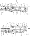
- FIG. 1 shows a vehicle door handle assembly 1 in a rest position.
- the vehicle door handle assembly 1 comprises a bracket 10 and a handle 2.
- the bracket 10 is designed to be fixed on the vehicle door (not represented). In this rest position, the handle 2 is retracted into the bracket 10 in order to be at the same level of the door body when installed.
- the handle 2 comprises a first extremity 22 and a second extremity 23 opposed to the first extremity 22.
- the first extremity 22 of the handle 2 is connected to a first lever 3 and the second extremity 23 of the handle 2 is connected to a second lever 4.
- the first lever 3 is also designed to be connected to an opening lever (not represented) to open a latch of the vehicle door.
- the first lever 3 is designed to rotate between a rest position (represented in figure 1 ) where the first extremity 22 of the handle 2 is in a rest position, a deployed position (represented in figure 2 ) where the first extremity 22 of the handle 2 is in a deployed position outside the bracket 10 and an opening position (represented on figure 3 ) where the first lever 3 actuates the opening lever.
- the first lever 3 comprises a pivot connection 33 with the bracket 10 around which the first lever 3 rotates between its different positions.
- a first extremity of the first lever 3 is connected to the first extremity 22 of the handle 2 and a second extremity of the first lever 3, is connected to the opening lever.
- the first lever 3 may also comprises an elastic mean 34 (visible in figure 2 ) passively bringing back said first lever 3 from its opening position to its deployed position.
- This elastic mean 34 may be a spring positioned for example on the pivot connection 33 between the first lever 3 and the bracket 10.
- the second extremity 23 of the handle 2 is connected to a second lever 4.
- the second lever 4 is designed to rotate between a rest position (represented in figure 1 ) where the second extremity 23 of the handle 2 is in a rest position, and a deployed position (represented in figures 2 and 3 ) where the second extremity 23 of the handle 2 is in a deployed position outside the bracket 10.
- the second lever 4 comprises a pivot connection 41 with the bracket 10 around which the second lever 4 rotates between its different positions.
- a first extremity of the second lever 4 is connected to the second extremity 23 of the handle 2.
- the connections between the first lever 3 and the first extremity 22 of the handle 2 and between the second lever 4 and the second extremity 23 of the handle 2 comprise preferably a pivot-slide connection and a pivot connection.
- the connection between the second lever 4 and the second extremity 23 of the handle 2 is a pivot-slide connection.
- the second extremity 23 of the handle 2 comprises here a recess 24 and the second lever 4 comprises a slide opening 44 for example to receive a pin (not represented).
- the connection between the first lever 3 and the first extremity 22 of the handle 2 is here a pivot connection 21.
- the first 22 or second 23 extremity of the handle 2, bearing the pivot-slide connection with the first 3 or second 4 lever, may comprises a hollow compartment.
- the first 3 or second 4 lever may be inserted into this hollow compartment and attached to the first 22 or second 23 extremity of the handle 2.
- This attachment of the first extremity of the lever 3, 4 could be performed by a first fixing clip 25.
- An example of a first fixing clip 25 is illustrated with more details in figure 5 .
- This first fixing clip 25 comprises an oblong opening 251 in which the pin connected to the first extremity of the lever 3, 4 can slide.
- the first fixing clip 25 also comprises some hooks 252 to be fixed to the side of the first 22 or second 23 extremity of the handle2.
- the other extremity of the handle 2, bearing the pivot connection with the other lever, may also comprises a hollow compartment.
- the lever may also be inserted into this hollow compartment and attached to the extremity of the handle 2, for example by a second fixing clip 26.
- the first 3 and second 4 levers may be connected together with at least one rod 7 in order to synchronize the movements of the two levers 3, 4. More exactly, the rod 7 transmits the rotation of the second lever 4 from its rest position to its deployed position to the first lever 3, rotating said first lever 3 from its rest position to its deployed position.
- the rod 7 may comprise a pivot-slide connection with any of the first 3 or second lever 4 so that the first lever 3 can rotate from its rest position to its deployed position or from its deployed position to its opening position without rotating the second lever 4.
- the rod 7 comprises a first extremity connected to a second extremity of the first lever 3 by a pivot connection 32.
- the rod 7 comprises a second extremity connected to the second lever 4 by a pivot-slide connection.
- the second extremity of the rod 7 comprises a slide opening 71 and the second extremity of the second lever 4 comprises a pin 42 inserted into said slide opening 71.
- the handle 2, the first lever 3, the second 4 lever and the rod 7 are designed and connected like a parallelogram and move together synchronously.
- the other connection of the rod 7 with any of the first 3 or second lever 4 is preferably a pivot connection.
- the vehicle door handle assembly 1 could also comprise an actuator 5 connected to the second lever 4 in order to rotate the second lever 4 between its rest position and its deployed position.
- the actuator 5 could comprise an electric motor 51 in order to pull or push the second lever 4 according to the direction of rotation of said electric motor 51.
- the actuator 5 may also comprise a slider-crank linkage 52 in order to convert the rotational movement of the electric motor 51 into a linear movement.
- the slider-crank linkage 52 may be connected directly to a second extremity of the second lever 4 or connected to any of the at least one rod 7.
- the actuator 5 is preferably installed into a housing (not represented).
- the figures 1 to 3 represent the different positions and cinematic steps of the deployment and retraction of the handle 2.
- figure 1 is a representation of a rest position where the handle 2 is retracted into the bracket 10 in order to be at the same level of the door body when installed.
- the first lever 3 and the second lever 4 are in their rest position. These two levers 3 and 4 are maintained in their rest position due to the actuator 5.
- the inside of the handle 2 may also rest on a rest portion 11 of the bracket 10 placed between the first 22 and second 23 extremities of the handle 2.
- Figure 2 represents a deployed position of the handle 2 where the first lever 3 and the second lever 4 are in their deployed position. These two levers 3 and 4 are maintained in their deployed position due to the actuator 5.
- Figure 3 represents an opening position of the handle 2 where the user can grab the handle 2 and pull it in order to open the vehicle door.
- the handle 2 When the user pulls the handle 2, it rotates around the pivot connection 21 between the first extremity 22 of the handle 2 and the first lever 3.
- the first extremity 22 of the handle 2 is pulled in an opening position rotating the first lever 3 from its deployed position to its opening position.
- the rotation of the first lever 3 is not transmitted to the second lever 4 by the rod 7 due to the pivot-slide connection.
- the first lever 3 rotates back to its deployed position due to its elastic mean 34.
- the vehicle door handle assembly 1 also comprises a dumper 6 visible in figures 4 to 7 .
- This dumper 6 is positioned into one of the first 22 or second 23 extremity of the handle 2 in order to dampen the slide of the extremity of the first 3 or second 4 lever in its pivot-slide connection with the handle 2 when the first extremity 22 of the handle 2 move from its opening position to its deployed position.
- the movement of the handle 2 from its opening position to its deployed position is slown down and the sound emitted by the handle is soft.
- the dumper 6 could be positioned into the hollow compartment of the first 22 or second 23 extremity of the handle 2.
- the dumper 6 could be an elastic part placed at the extremity of the pivot-slide connection.
- the extremity of the first 3 or second 4 lever is not in contact with the dumper 6.
- the handle 2 is in its deployed position, as represented on figure 7 , the extremity of the first 3 or second 4 lever presses the dumper 6.
- the dumper 6 could be made of a thermoplastic elastomer.
- this thermoplastic elastomer may have a hardness of Shore A between 50 and 60, preferably a hardness of Shore A 55.
- the dumper 6 could comprise at least one strip 61 designed to come in contact with the extremity of the first 3 or second 4 lever when the handle 2 is in its deployed position. This strip 61 increases the damping of the first 3 or second 4 lever and the mitigation of the sound.
- the dumper 6 could also comprise a recess 62 designed to receive a pin in order to maintain said dumper 6 into the first 22 or second 23 extremity of the handle 2.
- this pin could be a pin of the fixing clip 25 of the first extremity of the first 3 or second lever 4 to the first 22 or second 23 extremity of the handle 2.
Landscapes
- Lock And Its Accessories (AREA)
Abstract
Description
- The present invention relates to a vehicle door handle assembly, in particular of the type with a handle translating from a rest position where the handle is retracted and a deployed position where the handle is deployed and can be taken in hand and opened.
- Such vehicle door handle assemblies have generally three positions: a rest position where the handle is retracted and flush with the vehicle door body, a deployed position where the handle steps out of the vehicle door body and an opening position where the handle is pulled by a user in order to unlock and open the vehicle door. Such vehicle door handle assemblies with a handle translating between its rest position and its deployed position is becoming more common and requested by manufacturers.
- When the user releases the handle and it comes back from its opening position to its deployed position, the manufacturers may require a transition with a soft sound in order to increase the feeling quality of the handle to the user. For standard handles which do not have a rest position, it is current to have a dumper positioned between the handle and the vehicle door body or a bracket of the vehicle door handle assembly. However, for vehicle door handle assembly having a rest position, where the handle is retracted and flush with the vehicle door body or a bracket, such method is hardly transposable due to the complexity of the mechanism permitting the movement between the rest position and the deployed position.
- A known solution to this problem is to add a damper into the mechanism in order to slow down the return of one extremity of the handle from its opening position to its deployed position. However, this solution has a high cost and is complex to integrate into the mechanism.
- One aim of the present invention is to provide an economic and simple solution permitting a transition with a soft sound when the user releases the handle and it comes back from its opening position to its deployed position.
- To this end, the invention relates to a vehicle door handle assembly comprising a bracket and a handle, said handle comprising a first extremity and a second extremity opposed to the first extremity,
- the first extremity of the handle being connected to a first extremity of a first lever, said first lever being designed to be connected to an opening lever to open a latch of the vehicle door, said first lever being designed to rotate between a rest position where the first extremity of the handle is in a rest position, a deployed position where the first extremity of the handle is in a deployed position outside the bracket and an opening position where the first lever actuates the opening lever,
- the second extremity of the handle being connected to a first extremity of a second lever, said second lever being designed to rotate between a rest position where the second extremity of the handle is in a rest position and a deployed position where the second extremity of the handle is in a deployed position outside the bracket,
- at least one of the first or second lever being connected to its respective first or second extremity of the handle by a pivot-slide connection,
- wherein the vehicle door handle assembly also comprises a dumper positioned into one of the first or second extremity of the handle in order to dampen the sliding of the extremity of the first or second lever in its pivot-slide connection with the handle when the first extremity of the handle moves from its opening position to its deployed position.
- The vehicle door handle assembly may further comprise one or more of the features described hereinafter, considered alone or in combination.
- The dumper could be an elastic part placed at the extremity of the pivot-slide connection, the extremity of the first or second lever pressing the dumper when the handle is in its deployed position.
- The dumper could be made of a thermoplastic elastomer.
- The thermoplastic elastomer could have a hardness of Shore A between 50 and 60, preferably a hardness of Shore A 55.
- The dumper could comprise at least one strip designed to come in contact with the extremity of the first or second lever when the handle is in its deployed position.
- The first or second extremity of the handle bearing the pivot-slide connection with the first or second lever could have a hollow compartment, the first or second lever being inserted into this hollow compartment, and the dumper could also be positioned onto this hollow compartment.
- The dumper could comprise a recess designed to receive a pin in order to maintain said dumper into the first or second extremity of the handle.
- The pin could be a pin of a fixing clip of the extremity of the first or second lever to the first or second extremity of the handle.
- Further features and advantages of the invention will become apparent from the following description, given by way of non-limiting example, with reference to the appended drawings, in which:
-
Figure 1 is a side view of a schematic representation of a vehicle door handle assembly in a rest position, -
Figure 2 is a side view of a schematic representation of a vehicle door handle assembly in a deployed position, -
Figure 3 is a side view of a schematic representation of a vehicle door handle assembly in an opening position, -
Figure 4 is a exploded view of the vehicle door handle assembly, -
Figure 5 is a view of a fixing clip and a dumper -
Figure 6 is a cut view of an extremity of the handle in its opening position, -
Figure 7 is a cut view of an extremity of the handle in its deployed position. - In these figures, identical elements bear the same reference numbers. The following implementations are examples. Although the description refers to one or more embodiments, this does not necessarily mean that each reference relates to the same embodiment or that the features apply only to a single embodiment. Individual features of different embodiments can also be combined or interchanged to provide other embodiments.
-
Figure 1 shows a vehicledoor handle assembly 1 in a rest position. The vehicledoor handle assembly 1 comprises abracket 10 and ahandle 2. Thebracket 10 is designed to be fixed on the vehicle door (not represented). In this rest position, thehandle 2 is retracted into thebracket 10 in order to be at the same level of the door body when installed. - The
handle 2 comprises afirst extremity 22 and asecond extremity 23 opposed to thefirst extremity 22. Thefirst extremity 22 of thehandle 2 is connected to afirst lever 3 and thesecond extremity 23 of thehandle 2 is connected to asecond lever 4. - The
first lever 3 is also designed to be connected to an opening lever (not represented) to open a latch of the vehicle door. Thefirst lever 3 is designed to rotate between a rest position (represented infigure 1 ) where thefirst extremity 22 of thehandle 2 is in a rest position, a deployed position (represented infigure 2 ) where thefirst extremity 22 of thehandle 2 is in a deployed position outside thebracket 10 and an opening position (represented onfigure 3 ) where thefirst lever 3 actuates the opening lever. - More precisely, the
first lever 3 comprises apivot connection 33 with thebracket 10 around which thefirst lever 3 rotates between its different positions. A first extremity of thefirst lever 3 is connected to thefirst extremity 22 of thehandle 2 and a second extremity of thefirst lever 3, is connected to the opening lever. Thefirst lever 3 may also comprises an elastic mean 34 (visible infigure 2 ) passively bringing back saidfirst lever 3 from its opening position to its deployed position. Thiselastic mean 34 may be a spring positioned for example on thepivot connection 33 between thefirst lever 3 and thebracket 10. - The
second extremity 23 of thehandle 2 is connected to asecond lever 4. Thesecond lever 4 is designed to rotate between a rest position (represented infigure 1 ) where thesecond extremity 23 of thehandle 2 is in a rest position, and a deployed position (represented infigures 2 and3 ) where thesecond extremity 23 of thehandle 2 is in a deployed position outside thebracket 10. Thesecond lever 4 comprises apivot connection 41 with thebracket 10 around which thesecond lever 4 rotates between its different positions. A first extremity of thesecond lever 4 is connected to thesecond extremity 23 of thehandle 2. - The connections between the
first lever 3 and thefirst extremity 22 of thehandle 2 and between thesecond lever 4 and thesecond extremity 23 of thehandle 2 comprise preferably a pivot-slide connection and a pivot connection. In the examples represented infigures 1 to 3 , the connection between thesecond lever 4 and thesecond extremity 23 of thehandle 2 is a pivot-slide connection. Thesecond extremity 23 of thehandle 2 comprises here arecess 24 and thesecond lever 4 comprises aslide opening 44 for example to receive a pin (not represented). The connection between thefirst lever 3 and thefirst extremity 22 of thehandle 2 is here apivot connection 21. - The first 22 or second 23 extremity of the
handle 2, bearing the pivot-slide connection with the first 3 or second 4 lever, may comprises a hollow compartment. The first 3 or second 4 lever may be inserted into this hollow compartment and attached to the first 22 or second 23 extremity of thehandle 2. This attachment of the first extremity of thelever first fixing clip 25. An example of afirst fixing clip 25 is illustrated with more details infigure 5 . Thisfirst fixing clip 25 comprises anoblong opening 251 in which the pin connected to the first extremity of thelever first fixing clip 25 also comprises somehooks 252 to be fixed to the side of the first 22 or second 23 extremity of the handle2. - The other extremity of the
handle 2, bearing the pivot connection with the other lever, may also comprises a hollow compartment. The lever may also be inserted into this hollow compartment and attached to the extremity of thehandle 2, for example by asecond fixing clip 26. - The first 3 and second 4 levers may be connected together with at least one
rod 7 in order to synchronize the movements of the twolevers rod 7 transmits the rotation of thesecond lever 4 from its rest position to its deployed position to thefirst lever 3, rotating saidfirst lever 3 from its rest position to its deployed position. Therod 7 may comprise a pivot-slide connection with any of the first 3 orsecond lever 4 so that thefirst lever 3 can rotate from its rest position to its deployed position or from its deployed position to its opening position without rotating thesecond lever 4. In the example illustrated infigures 1 to 3 , therod 7 comprises a first extremity connected to a second extremity of thefirst lever 3 by apivot connection 32. Therod 7 comprises a second extremity connected to thesecond lever 4 by a pivot-slide connection. The second extremity of therod 7 comprises aslide opening 71 and the second extremity of thesecond lever 4 comprises apin 42 inserted into saidslide opening 71. Thehandle 2, thefirst lever 3, the second 4 lever and therod 7 are designed and connected like a parallelogram and move together synchronously. The other connection of therod 7 with any of the first 3 orsecond lever 4 is preferably a pivot connection. - The vehicle
door handle assembly 1 could also comprise anactuator 5 connected to thesecond lever 4 in order to rotate thesecond lever 4 between its rest position and its deployed position. Theactuator 5 could comprise anelectric motor 51 in order to pull or push thesecond lever 4 according to the direction of rotation of saidelectric motor 51. Theactuator 5 may also comprise a slider-crank linkage 52 in order to convert the rotational movement of theelectric motor 51 into a linear movement. The slider-crank linkage 52 may be connected directly to a second extremity of thesecond lever 4 or connected to any of the at least onerod 7. Theactuator 5 is preferably installed into a housing (not represented). - The
figures 1 to 3 represent the different positions and cinematic steps of the deployment and retraction of thehandle 2. - As described above,
figure 1 is a representation of a rest position where thehandle 2 is retracted into thebracket 10 in order to be at the same level of the door body when installed. Thefirst lever 3 and thesecond lever 4 are in their rest position. These twolevers actuator 5. In this rest position, the inside of thehandle 2 may also rest on arest portion 11 of thebracket 10 placed between the first 22 and second 23 extremities of thehandle 2. -
Figure 2 represents a deployed position of thehandle 2 where thefirst lever 3 and thesecond lever 4 are in their deployed position. These twolevers actuator 5. -
Figure 3 represents an opening position of thehandle 2 where the user can grab thehandle 2 and pull it in order to open the vehicle door. When the user pulls thehandle 2, it rotates around thepivot connection 21 between thefirst extremity 22 of thehandle 2 and thefirst lever 3. Thefirst extremity 22 of thehandle 2 is pulled in an opening position rotating thefirst lever 3 from its deployed position to its opening position. The rotation of thefirst lever 3 is not transmitted to thesecond lever 4 by therod 7 due to the pivot-slide connection. When the user releases thehandle 2, thefirst lever 3 rotates back to its deployed position due to itselastic mean 34. - The vehicle
door handle assembly 1 also comprises adumper 6 visible infigures 4 to 7 . Thisdumper 6 is positioned into one of the first 22 or second 23 extremity of thehandle 2 in order to dampen the slide of the extremity of the first 3 or second 4 lever in its pivot-slide connection with thehandle 2 when thefirst extremity 22 of thehandle 2 move from its opening position to its deployed position. Thus, the movement of thehandle 2 from its opening position to its deployed position is slown down and the sound emitted by the handle is soft. For example, thedumper 6 could be positioned into the hollow compartment of the first 22 or second 23 extremity of thehandle 2. - The
dumper 6 could be an elastic part placed at the extremity of the pivot-slide connection. When thehandle 2 is in its opening position, as represented infigure 6 , the extremity of the first 3 or second 4 lever is not in contact with thedumper 6. When thehandle 2 is in its deployed position, as represented onfigure 7 , the extremity of the first 3 or second 4 lever presses thedumper 6. - The
dumper 6 could be made of a thermoplastic elastomer. To enhance the quality of the sound emitted by thehandle 2, this thermoplastic elastomer may have a hardness of Shore A between 50 and 60, preferably a hardness of Shore A 55. - As represented in
figures 5 to 7 , thedumper 6 could comprise at least onestrip 61 designed to come in contact with the extremity of the first 3 or second 4 lever when thehandle 2 is in its deployed position. Thisstrip 61 increases the damping of the first 3 or second 4 lever and the mitigation of the sound. - The
dumper 6 could also comprise arecess 62 designed to receive a pin in order to maintain saiddumper 6 into the first 22 or second 23 extremity of thehandle 2. Advantageously, this pin could be a pin of the fixingclip 25 of the first extremity of the first 3 orsecond lever 4 to the first 22 or second 23 extremity of thehandle 2. -
- 1: vehicle door handle assembly
- 10: bracket
- 11: rest bracket
- 2: handle
- 21: pivot of the first extremity of the handle
- 22: first extremity of the handle
- 23: second extremity of the handle
- 24: slide opening of the second extremity of the handle
- 25: first fixing clip
- 251: oblong opening of the first clip
- 252: hook of fixation of the first clip
- 253: pin
- 26: second fixing clip
- 3: first lever
- 32: pivot connection of the first lever with the rod
- 33: pivot connection of the first lever with bracket
- 34: elastic mean
- 4: second lever
- 41: pivot connection of the second lever with the bracket
- 42: pivot connection of the second lever with the rod
- 44: pivot of the second lever with the slide of the second extremity of the handle
- 5: actuator
- 51: electric motor
- 52: slider-crank linkage
- 53: printed circuit board
- 6: dumper
- 61: strip
- 62: recess of the dumper
- 7: rod
- 71: slide of the rod
Claims (8)
- Vehicle door handle assembly (1) comprising a bracket (10) and a handle (2), said handle (2) comprising a first extremity (22) and a second extremity (23) opposed to the first extremity (22),the first extremity (22) of the handle (2) being connected to a first extremity of a first lever (3), said first lever (3) being designed to be connected to an opening lever to open a latch of the vehicle door, said first lever (3) being designed to rotate between a rest position where the first extremity (22) of the handle (2) is in a rest position, a deployed position where the first extremity (22) of the handle (2) is in a deployed position outside the bracket (10) and an opening position where the first lever (3) actuates the opening lever,the second extremity (23) of the handle (2) being connected to a first extremity of a second lever (4), said second lever (4) being designed to rotate between a rest position where the second extremity (23) of the handle (2) is in a rest position and a deployed position where the second extremity (23) of the handle (2) is in a deployed position outside the bracket (10),at least one of the first (3) or second (4) lever being connected to its respective first (22) or second (23) extremity of the handle (2) by a pivot-slide connection, wherein the vehicle door handle assembly (1) also comprises a dumper (6) positioned into one of the first (22) or second (23) extremity of the handle (2) in order to dampen the sliding of the extremity of the first (3) or second (4) lever in its pivot-slide connection with the handle (2) when the first extremity (22) of the handle (2) moves from its opening position to its deployed position.
- Vehicle door handle assembly (1) according to the preceding claim, wherein the dumper (6) is an elastic part placed at the extremity of the pivot-slide connection, the extremity of the first (3) or second (4) lever pressing the dumper (6) when the handle (2) is in its deployed position.
- Vehicle door handle assembly (1) according to claim 2, wherein the dumper (6) is made of a thermoplastic elastomer.
- Vehicle door handle assembly (1) according to claim 3, wherein the thermoplastic elastomer has a hardness of Shore A between 50 and 60, preferably a hardness of Shore A 55.
- Vehicle door handle assembly (1) according to anyone of claims 2 to 4, wherein the dumper (6) comprises at least one strip (61) designed to come in contact with the extremity of the first (3) or second (4) lever when the handle (2) is in its deployed position.
- Vehicle door handle assembly (1) according to anyone of the preceding claims, wherein the first (22) or second (23) extremity of the handle (2) bearing the pivot-slide connection with the first (3) or second (4) lever has a hollow compartment, the first (3) or second (4) lever being inserted into this hollow compartment, and wherein the dumper (6) is also positioned onto this hollow compartment.
- Vehicle door handle assembly (1) according to claim 6, wherein the dumper (6) comprises a recess (62) designed to receive a pin in order to maintain said dumper (6) into the first (22) or second (23) extremity of the handle (2).
- Vehicle door handle assembly (1) according to claim 7, wherein the pin is a pin (252) of a fixing clip (25) of the extremity of the first (3) or second lever (4) to the first (22) or second (23) extremity of the handle (2).
Priority Applications (4)
| Application Number | Priority Date | Filing Date | Title |
|---|---|---|---|
| ES22165303T ES3032706T3 (en) | 2022-03-30 | 2022-03-30 | Vehicle door handle assembly |
| EP22165303.3A EP4253703B1 (en) | 2022-03-30 | 2022-03-30 | Vehicle door handle assembly |
| CN202310305683.0A CN116892330A (en) | 2022-03-30 | 2023-03-27 | door handle assembly |
| US18/193,013 US12270234B2 (en) | 2022-03-30 | 2023-03-30 | Vehicle door handle assembly |
Applications Claiming Priority (1)
| Application Number | Priority Date | Filing Date | Title |
|---|---|---|---|
| EP22165303.3A EP4253703B1 (en) | 2022-03-30 | 2022-03-30 | Vehicle door handle assembly |
Publications (2)
| Publication Number | Publication Date |
|---|---|
| EP4253703A1 true EP4253703A1 (en) | 2023-10-04 |
| EP4253703B1 EP4253703B1 (en) | 2025-05-07 |
Family
ID=80999334
Family Applications (1)
| Application Number | Title | Priority Date | Filing Date |
|---|---|---|---|
| EP22165303.3A Active EP4253703B1 (en) | 2022-03-30 | 2022-03-30 | Vehicle door handle assembly |
Country Status (4)
| Country | Link |
|---|---|
| US (1) | US12270234B2 (en) |
| EP (1) | EP4253703B1 (en) |
| CN (1) | CN116892330A (en) |
| ES (1) | ES3032706T3 (en) |
Citations (5)
| Publication number | Priority date | Publication date | Assignee | Title |
|---|---|---|---|---|
| US5123687A (en) * | 1990-02-01 | 1992-06-23 | Mercedes-Benz Ag | Grip control for a handle for unlocking vehicle doors |
| CN108547523A (en) * | 2018-07-06 | 2018-09-18 | 伟速达(中国)汽车安全系统有限公司 | A kind of novel concealed exterior door handle for automobile component |
| KR102104888B1 (en) * | 2019-01-24 | 2020-04-27 | 주식회사 프라코 | Auto flush outside door handle assembly for vehicle |
| CN113863796A (en) * | 2020-06-30 | 2021-12-31 | 比亚迪股份有限公司 | Door handle device and vehicle with same |
| US20220065003A1 (en) * | 2020-08-28 | 2022-03-03 | Hyundai Motor Company | Vehicle door handle assembly |
Family Cites Families (8)
| Publication number | Priority date | Publication date | Assignee | Title |
|---|---|---|---|---|
| DE3931866C1 (en) * | 1989-09-23 | 1991-03-21 | Mercedes-Benz Aktiengesellschaft, 7000 Stuttgart, De | |
| IT1319907B1 (en) * | 2000-02-23 | 2003-11-12 | Valeo Sicurezza Abitacolo Spa | HANDLE FOR A DOOR OF A VEHICLE. |
| US8701353B2 (en) * | 2012-06-29 | 2014-04-22 | Ford Global Technologies, Llc | Deployable door handle for vehicles |
| GB2517348B (en) * | 2012-09-25 | 2015-09-23 | Jaguar Land Rover Ltd | Retractable handle arrangement |
| CN108474221B (en) * | 2015-10-21 | 2021-03-09 | 伊利诺斯工具制品有限公司 | vehicle door handle |
| FR3047035B1 (en) * | 2016-01-21 | 2021-06-11 | Peugeot Citroen Automobiles Sa | MOTOR VEHICLE EXTERNAL OPENING CONTROL |
| DE102017130573A1 (en) * | 2017-12-19 | 2019-06-19 | Huf Hülsbeck & Fürst GmbH & Co KG | Door handle assembly of a motor vehicle |
| CN114150946A (en) * | 2021-12-21 | 2022-03-08 | 伟速达(中国)汽车安全系统有限公司 | Mechanical type automatic withdrawing automobile outer pull handle |
-
2022
- 2022-03-30 ES ES22165303T patent/ES3032706T3/en active Active
- 2022-03-30 EP EP22165303.3A patent/EP4253703B1/en active Active
-
2023
- 2023-03-27 CN CN202310305683.0A patent/CN116892330A/en active Pending
- 2023-03-30 US US18/193,013 patent/US12270234B2/en active Active
Patent Citations (5)
| Publication number | Priority date | Publication date | Assignee | Title |
|---|---|---|---|---|
| US5123687A (en) * | 1990-02-01 | 1992-06-23 | Mercedes-Benz Ag | Grip control for a handle for unlocking vehicle doors |
| CN108547523A (en) * | 2018-07-06 | 2018-09-18 | 伟速达(中国)汽车安全系统有限公司 | A kind of novel concealed exterior door handle for automobile component |
| KR102104888B1 (en) * | 2019-01-24 | 2020-04-27 | 주식회사 프라코 | Auto flush outside door handle assembly for vehicle |
| CN113863796A (en) * | 2020-06-30 | 2021-12-31 | 比亚迪股份有限公司 | Door handle device and vehicle with same |
| US20220065003A1 (en) * | 2020-08-28 | 2022-03-03 | Hyundai Motor Company | Vehicle door handle assembly |
Also Published As
| Publication number | Publication date |
|---|---|
| US20230313575A1 (en) | 2023-10-05 |
| US12270234B2 (en) | 2025-04-08 |
| EP4253703B1 (en) | 2025-05-07 |
| ES3032706T3 (en) | 2025-07-23 |
| CN116892330A (en) | 2023-10-17 |
Similar Documents
| Publication | Publication Date | Title |
|---|---|---|
| US8342583B2 (en) | Vehicle panel control system | |
| EP3106595A1 (en) | Handle for a vehicle door | |
| US20200354996A1 (en) | Door handle assembly of a vehicle door | |
| EP3712362B1 (en) | Door handle assembly comprising an outer bezel mechanism and an inner bracket mechanism | |
| CN112204217A (en) | Door leaf handle device, in particular for a motor vehicle | |
| US20200332575A1 (en) | Door handle assembly of a motor vehicle | |
| US20180252009A1 (en) | Handle device for a motor vehicle | |
| EP4261372A1 (en) | Vehicle door handle assembly | |
| EP4253703A1 (en) | Vehicle door handle assembly | |
| US20200277808A1 (en) | Power child lock operating device | |
| KR20190141910A (en) | Retractable outside door handle assembly for vehicle | |
| CA2117509A1 (en) | Tailgate handle assembly and method of assembly thereof | |
| US20020046440A1 (en) | Vehicle door handle | |
| US20020149222A1 (en) | Adjustable armrest for motor vehicle inside panel | |
| EP4234860B1 (en) | Vehicle door handle assembly | |
| US12385298B2 (en) | Vehicle door handle assembly | |
| EP1445151A1 (en) | An electromechanically controlled retractable step for a vehicle | |
| CN114622780A (en) | Unlocking device and vehicle | |
| US12540496B2 (en) | Actuating mechanism for actuating covers for vehicles | |
| JP2005337681A (en) | Refrigerator door handle | |
| EP4261374A1 (en) | Vehicle door handle assembly | |
| EP4407128A1 (en) | Electric vehicle door handle assembly | |
| EP4353931A1 (en) | Vehicle door handle assembly with a shock absorber | |
| CN209212082U (en) | Box lock system | |
| US20250207440A1 (en) | Double pull inside door handle mechanism with electrical and mechanical actuation |
Legal Events
| Date | Code | Title | Description |
|---|---|---|---|
| PUAI | Public reference made under article 153(3) epc to a published international application that has entered the european phase |
Free format text: ORIGINAL CODE: 0009012 |
|
| STAA | Information on the status of an ep patent application or granted ep patent |
Free format text: STATUS: THE APPLICATION HAS BEEN PUBLISHED |
|
| AK | Designated contracting states |
Kind code of ref document: A1 Designated state(s): AL AT BE BG CH CY CZ DE DK EE ES FI FR GB GR HR HU IE IS IT LI LT LU LV MC MK MT NL NO PL PT RO RS SE SI SK SM TR |
|
| STAA | Information on the status of an ep patent application or granted ep patent |
Free format text: STATUS: REQUEST FOR EXAMINATION WAS MADE |
|
| 17P | Request for examination filed |
Effective date: 20240221 |
|
| RBV | Designated contracting states (corrected) |
Designated state(s): AL AT BE BG CH CY CZ DE DK EE ES FI FR GB GR HR HU IE IS IT LI LT LU LV MC MK MT NL NO PL PT RO RS SE SI SK SM TR |
|
| RAP3 | Party data changed (applicant data changed or rights of an application transferred) |
Owner name: MINEBEA ACCESSSOLUTIONS ITALIA S.P.A. |
|
| GRAP | Despatch of communication of intention to grant a patent |
Free format text: ORIGINAL CODE: EPIDOSNIGR1 |
|
| STAA | Information on the status of an ep patent application or granted ep patent |
Free format text: STATUS: GRANT OF PATENT IS INTENDED |
|
| INTG | Intention to grant announced |
Effective date: 20241223 |
|
| GRAS | Grant fee paid |
Free format text: ORIGINAL CODE: EPIDOSNIGR3 |
|
| GRAA | (expected) grant |
Free format text: ORIGINAL CODE: 0009210 |
|
| STAA | Information on the status of an ep patent application or granted ep patent |
Free format text: STATUS: THE PATENT HAS BEEN GRANTED |
|
| AK | Designated contracting states |
Kind code of ref document: B1 Designated state(s): AL AT BE BG CH CY CZ DE DK EE ES FI FR GB GR HR HU IE IS IT LI LT LU LV MC MK MT NL NO PL PT RO RS SE SI SK SM TR |
|
| REG | Reference to a national code |
Ref country code: GB Ref legal event code: FG4D |
|
| REG | Reference to a national code |
Ref country code: CH Ref legal event code: EP |
|
| REG | Reference to a national code |
Ref country code: DE Ref legal event code: R096 Ref document number: 602022014109 Country of ref document: DE |
|
| REG | Reference to a national code |
Ref country code: IE Ref legal event code: FG4D |
|
| REG | Reference to a national code |
Ref country code: ES Ref legal event code: FG2A Ref document number: 3032706 Country of ref document: ES Kind code of ref document: T3 Effective date: 20250723 |
|
| REG | Reference to a national code |
Ref country code: NL Ref legal event code: MP Effective date: 20250507 |
|
| PG25 | Lapsed in a contracting state [announced via postgrant information from national office to epo] |
Ref country code: FI Free format text: LAPSE BECAUSE OF FAILURE TO SUBMIT A TRANSLATION OF THE DESCRIPTION OR TO PAY THE FEE WITHIN THE PRESCRIBED TIME-LIMIT Effective date: 20250507 Ref country code: PT Free format text: LAPSE BECAUSE OF FAILURE TO SUBMIT A TRANSLATION OF THE DESCRIPTION OR TO PAY THE FEE WITHIN THE PRESCRIBED TIME-LIMIT Effective date: 20250908 |
|
| REG | Reference to a national code |
Ref country code: LT Ref legal event code: MG9D |
|
| PG25 | Lapsed in a contracting state [announced via postgrant information from national office to epo] |
Ref country code: GR Free format text: LAPSE BECAUSE OF FAILURE TO SUBMIT A TRANSLATION OF THE DESCRIPTION OR TO PAY THE FEE WITHIN THE PRESCRIBED TIME-LIMIT Effective date: 20250808 Ref country code: NO Free format text: LAPSE BECAUSE OF FAILURE TO SUBMIT A TRANSLATION OF THE DESCRIPTION OR TO PAY THE FEE WITHIN THE PRESCRIBED TIME-LIMIT Effective date: 20250807 |
|
| PG25 | Lapsed in a contracting state [announced via postgrant information from national office to epo] |
Ref country code: NL Free format text: LAPSE BECAUSE OF FAILURE TO SUBMIT A TRANSLATION OF THE DESCRIPTION OR TO PAY THE FEE WITHIN THE PRESCRIBED TIME-LIMIT Effective date: 20250507 Ref country code: PL Free format text: LAPSE BECAUSE OF FAILURE TO SUBMIT A TRANSLATION OF THE DESCRIPTION OR TO PAY THE FEE WITHIN THE PRESCRIBED TIME-LIMIT Effective date: 20250507 |
|
| REG | Reference to a national code |
Ref country code: AT Ref legal event code: MK05 Ref document number: 1792624 Country of ref document: AT Kind code of ref document: T Effective date: 20250507 |
|
| PG25 | Lapsed in a contracting state [announced via postgrant information from national office to epo] |
Ref country code: BG Free format text: LAPSE BECAUSE OF FAILURE TO SUBMIT A TRANSLATION OF THE DESCRIPTION OR TO PAY THE FEE WITHIN THE PRESCRIBED TIME-LIMIT Effective date: 20250507 |
|
| PG25 | Lapsed in a contracting state [announced via postgrant information from national office to epo] |
Ref country code: HR Free format text: LAPSE BECAUSE OF FAILURE TO SUBMIT A TRANSLATION OF THE DESCRIPTION OR TO PAY THE FEE WITHIN THE PRESCRIBED TIME-LIMIT Effective date: 20250507 |
|
| PG25 | Lapsed in a contracting state [announced via postgrant information from national office to epo] |
Ref country code: AT Free format text: LAPSE BECAUSE OF FAILURE TO SUBMIT A TRANSLATION OF THE DESCRIPTION OR TO PAY THE FEE WITHIN THE PRESCRIBED TIME-LIMIT Effective date: 20250507 |
|
| PG25 | Lapsed in a contracting state [announced via postgrant information from national office to epo] |
Ref country code: RS Free format text: LAPSE BECAUSE OF FAILURE TO SUBMIT A TRANSLATION OF THE DESCRIPTION OR TO PAY THE FEE WITHIN THE PRESCRIBED TIME-LIMIT Effective date: 20250807 |
|
| PG25 | Lapsed in a contracting state [announced via postgrant information from national office to epo] |
Ref country code: IS Free format text: LAPSE BECAUSE OF FAILURE TO SUBMIT A TRANSLATION OF THE DESCRIPTION OR TO PAY THE FEE WITHIN THE PRESCRIBED TIME-LIMIT Effective date: 20250907 |
|
| PG25 | Lapsed in a contracting state [announced via postgrant information from national office to epo] |
Ref country code: LV Free format text: LAPSE BECAUSE OF FAILURE TO SUBMIT A TRANSLATION OF THE DESCRIPTION OR TO PAY THE FEE WITHIN THE PRESCRIBED TIME-LIMIT Effective date: 20250507 |
|
| PG25 | Lapsed in a contracting state [announced via postgrant information from national office to epo] |
Ref country code: DK Free format text: LAPSE BECAUSE OF FAILURE TO SUBMIT A TRANSLATION OF THE DESCRIPTION OR TO PAY THE FEE WITHIN THE PRESCRIBED TIME-LIMIT Effective date: 20250507 Ref country code: SM Free format text: LAPSE BECAUSE OF FAILURE TO SUBMIT A TRANSLATION OF THE DESCRIPTION OR TO PAY THE FEE WITHIN THE PRESCRIBED TIME-LIMIT Effective date: 20250507 |
|
| PG25 | Lapsed in a contracting state [announced via postgrant information from national office to epo] |
Ref country code: CZ Free format text: LAPSE BECAUSE OF FAILURE TO SUBMIT A TRANSLATION OF THE DESCRIPTION OR TO PAY THE FEE WITHIN THE PRESCRIBED TIME-LIMIT Effective date: 20250507 |
|
| PG25 | Lapsed in a contracting state [announced via postgrant information from national office to epo] |
Ref country code: EE Free format text: LAPSE BECAUSE OF FAILURE TO SUBMIT A TRANSLATION OF THE DESCRIPTION OR TO PAY THE FEE WITHIN THE PRESCRIBED TIME-LIMIT Effective date: 20250507 |
|
| PG25 | Lapsed in a contracting state [announced via postgrant information from national office to epo] |
Ref country code: SK Free format text: LAPSE BECAUSE OF FAILURE TO SUBMIT A TRANSLATION OF THE DESCRIPTION OR TO PAY THE FEE WITHIN THE PRESCRIBED TIME-LIMIT Effective date: 20250507 |
|
| REG | Reference to a national code |
Ref country code: DE Ref legal event code: R097 Ref document number: 602022014109 Country of ref document: DE |
|
| PLBE | No opposition filed within time limit |
Free format text: ORIGINAL CODE: 0009261 |
|
| STAA | Information on the status of an ep patent application or granted ep patent |
Free format text: STATUS: NO OPPOSITION FILED WITHIN TIME LIMIT |
|
| REG | Reference to a national code |
Ref country code: CH Ref legal event code: L10 Free format text: ST27 STATUS EVENT CODE: U-0-0-L10-L00 (AS PROVIDED BY THE NATIONAL OFFICE) Effective date: 20260318 |
|
| PGFP | Annual fee paid to national office [announced via postgrant information from national office to epo] |
Ref country code: DE Payment date: 20260313 Year of fee payment: 5 |
|
| 26N | No opposition filed |
Effective date: 20260210 |
|
| PGFP | Annual fee paid to national office [announced via postgrant information from national office to epo] |
Ref country code: IT Payment date: 20260309 Year of fee payment: 5 |
|
| PGFP | Annual fee paid to national office [announced via postgrant information from national office to epo] |
Ref country code: FR Payment date: 20260330 Year of fee payment: 5 |