EP4253638A1 - Clothing handling device - Google Patents
Clothing handling device Download PDFInfo
- Publication number
- EP4253638A1 EP4253638A1 EP23162725.8A EP23162725A EP4253638A1 EP 4253638 A1 EP4253638 A1 EP 4253638A1 EP 23162725 A EP23162725 A EP 23162725A EP 4253638 A1 EP4253638 A1 EP 4253638A1
- Authority
- EP
- European Patent Office
- Prior art keywords
- fragrance
- handling device
- operating
- clothing handling
- leaking
- Prior art date
- Legal status (The legal status is an assumption and is not a legal conclusion. Google has not performed a legal analysis and makes no representation as to the accuracy of the status listed.)
- Granted
Links
Images




Classifications
-
- D—TEXTILES; PAPER
- D06—TREATMENT OF TEXTILES OR THE LIKE; LAUNDERING; FLEXIBLE MATERIALS NOT OTHERWISE PROVIDED FOR
- D06F—LAUNDERING, DRYING, IRONING, PRESSING OR FOLDING TEXTILE ARTICLES
- D06F95/00—Laundry systems or arrangements of apparatus or machines; Mobile laundries
-
- D—TEXTILES; PAPER
- D06—TREATMENT OF TEXTILES OR THE LIKE; LAUNDERING; FLEXIBLE MATERIALS NOT OTHERWISE PROVIDED FOR
- D06F—LAUNDERING, DRYING, IRONING, PRESSING OR FOLDING TEXTILE ARTICLES
- D06F58/00—Domestic laundry dryers
- D06F58/20—General details of domestic laundry dryers
- D06F58/203—Laundry conditioning arrangements
-
- D—TEXTILES; PAPER
- D06—TREATMENT OF TEXTILES OR THE LIKE; LAUNDERING; FLEXIBLE MATERIALS NOT OTHERWISE PROVIDED FOR
- D06F—LAUNDERING, DRYING, IRONING, PRESSING OR FOLDING TEXTILE ARTICLES
- D06F25/00—Washing machines with receptacles, e.g. perforated, having a rotary movement, e.g. oscillatory movement, the receptacle serving both for washing and for centrifugally separating water from the laundry and having further drying means, e.g. using hot air
Definitions
- the present invention relates to the field of clothing handling technologies, and in particular, to a clothing handling device.
- Fragrance products of some existing clothing handling devices directly contact clothing, which may cause stains on the clothing, or a concentration cannot be well controlled and unblocking/blocking of a fragrance is inconvenient.
- the present invention is intended to resolve at least one of the above problems.
- Embodiments of the present invention relate to a clothing handling device, including a box and a fragrance assembly arranged in the box.
- the fragrance assembly includes an accommodating element and an operating element, and the operating element is configured to release or block a fragrance in the accommodating element.
- Embodiments of this application can realize convenient unblocking/blocking of the fragrance.
- the operating element and the accommodating element are stacked in a first direction and a second direction different from each other.
- the operating element includes an operating portion and a cap portion linked with the operating portion, and the cap portion releases or blocks the fragrance with a movement of the operating portion.
- the operating portion is staggered with respect to the accommodating element in a first direction, and the cap portion and the accommodating element are movable relative to each other in a second direction different from the first direction.
- the operating element includes an actuating member configured to cause the operating portion and/or the cap portion to move.
- the operating portion and/or the cap portion can move to unblock/block the fragrance.
- the actuating member includes a linkage shaft connected to the operating portion and an elastic linkage member corresponding to the linkage shaft.
- the elastic linkage member can drive the operating portion to move through the linkage shaft.
- the actuating member includes a stop shaft and an elastic stop member corresponding to the stop shaft, one of the stop shaft and the linkage shaft includes a bump, and the other includes a guiding surface and a groove corresponding to the bump.
- the operating portion and/or the cap portion can move and stop at a specific position.
- the guiding surface and the groove are arranged adjacent to and spaced apart from each other.
- the operating portion and/or the cap portion can move and stop at a specific position.
- the guiding surface is an inclined surface and is configured in such a way that the bump moves along the guiding surface into the groove when the operating portion drives the linkage shaft to move axially.
- the operating portion and the linkage shaft can smoothly move and reach a stop position.
- a plurality of operating portions and a plurality of cap portions are respectively arranged.
- the operating portions and the cap portions have the same size or different sizes. In this way, the fragrance concentration and type can be adjusted.
- the operating element includes a closing portion, a closing linkage shaft linked with the closing portion, and an elastic closing member corresponding to the closing linkage shaft.
- One of the closing linkage shaft and the stop shaft includes a closing bump, and the other includes a closing guiding surface corresponding to the closing bump.
- the closing guiding surface is an inclined plane and is configured in such a way that the closing bump drives the stop shaft to move axially when the closing portion drives the closing linkage shaft to move axially, so that the bump is disengaged from the groove and forms contact fit with the guiding surface.
- the operating element includes a receiving portion, and the operating portion, the cap portion, and the closing portion are at least partially located outside the receiving portion.
- the accommodating element includes an accommodating portion and a leaking portion, and the cap portion and the leaking portion are movable relative to each other to release or block the fragrance in the accommodating portion.
- the accommodating element includes a replaceable fragrance container including the accommodating portion, the leaking portion, and a lid.
- the accommodating element includes a cassette fixed to the box.
- the fragrance container is at least partially received in the cassette, the cassette includes an opening corresponding to the leaking portion, and the cap portion is configured to expose or cover the opening.
- the fragrance container can be mounted and the fragrance can be released or blocked.
- the cassette includes a plurality of openings, and a plurality of operating portions and a plurality of cap portions are respectively arranged. Quantities of the operating portions and the cap portions respectively correspond to a quantity of the openings.
- the fragrance can be more flexibly unblocked/blocked and adjusted.
- an air circulation area of at least one of the openings is different from those of the other openings.
- the fragrance concentration can be adjusted.
- the clothing handling device includes a clothing handling chamber and an airflow passage in fluid communication with the clothing handling chamber. A part of the fragrance assembly is exposed in the airflow passage.
- fragrance can be applied to clothing in the clothing handling chamber through the fragrance assembly and the airflow passage.
- the clothing handling device includes a clothing handling chamber.
- the leaking portion contacts circulating air passing through the clothing handling chamber after the cap portion leaves the leaking portion.
- the fragrance can be released through the leaking portion and the circulating air.
- a plurality of leaking portions are arranged on the accommodating element, and a cross-sectional area of at least one of the leaking portions exposed to the circulating air is different from those of the other leaking portions.
- a plurality of leaking portions are arranged on the accommodating element, and a plurality of operating portions and a plurality of cap portions are respectively arranged. Quantities of the operating portions and the cap portions respectively correspond to a quantity of the leaking portions.
- each of the leaking portions includes a plug made of a porous medium.
- the fragrance can be released through the leaking portion.
- FIG. 1 is a schematic front view of a clothing handling device according to an aspect of embodiments of the present invention.
- the aspect of the embodiments of the present invention relates to a clothing handling device 10, including a box 12 and a fragrance assembly 14 arranged in the box 12.
- FIG. 2 is a partial schematic cross-sectional view of a fragrance assembly of the clothing handling device in FIG. 1 .
- the fragrance assembly 14 includes an accommodating element 16 and an operating element 18.
- the operating element 18 is configured to release or block a fragrance in the accommodating element 16.
- Embodiments of this application can realize convenient unblocking/blocking of the fragrance.
- the fragrance assembly 14 is arranged in the box 12 to apply the fragrance to the clothing in the box 12.
- the fragrance is accommodated in the accommodating element 16 to reduce or avoid a possibility of direct contact between the fragrance and the clothing.
- the fragrance in the accommodating element 16 may be released or blocked through the operating element 18, which is less likely to be subjected to spatial and structural constraint compared with directly releasing or blocking the fragrance through the accommodating element 16. Therefore, the operation is more convenient.
- the operating element 18 and the accommodating element 16 are stacked in a first direction and a second direction different from each other.
- the operating element 18 and the accommodating element 16 may include parts stacked in the first direction X and parts stacked in the second direction Y respectively, so that the fragrance assembly 14 is less likely to be oversized in a single direction, and the fragrance may be unblocked/blocked in a direction that facilitates operation, which is less likely to be subjected to spatial and structural constraints.
- first and second herein are not intended to represent a priority, a significance, and the like, but to help distinguish between directions, shapes, structures, elements, and the like modified by them.
- the operating element 18 includes an operating portion 20 and a cap portion 22 linked with the operating portion 20, and the cap portion 22 may release or block the fragrance with a movement of the operating portion 20. In this way, the convenient unblocking/blocking of the fragrance can be realized.
- the operating portion 20 and the cap portion 22 may be respectively arranged at a position that facilitates operation and a position that does not facilitate operation.
- the operating portion 20 may be arranged outside the fragrance assembly 14 and the box 12 to facilitate operation
- the cap portion 22 may be arranged inside the fragrance assembly 14 and the box 12 to facilitate the release of the fragrance inside.
- the operating portion 20 is staggered with respect to the accommodating element 16 in a first direction, and the cap portion 22 and the accommodating element 16 are movable relative to each other in a second direction Y different from the first direction X.
- the operating portion 20 may be arranged above or below the accommodating element 16, and the cap portion 22 and the accommodating element 16 are movable relative to each other in a front-rear direction.
- the cap portion 22 may be arranged at an upper rear position or a lower rear position of the operating portion 20.
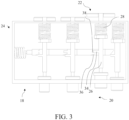
- FIG. 3 is a schematic top view of the operating element in FIG. 2 .
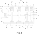
- FIG. 4 is another schematic top view similar to FIG. 3 .
- the operating element 18 includes an actuating member 24 configured to cause the operating portion 20 and/or the cap portion 22 to move.
- the operating portion 20 and/or the cap portion 22 can move to unblock/block the fragrance.
- the actuating member 24 can drive the cap portion 22 to move to release the fragrance when the operating portion 20 is driven to move by a force. As shown in FIG. 2 and FIG. 4 , the actuating member 24 can further drive the operating portion 20 and the cap portion 22 to return to an initial position to block the fragrance.
- the actuating member 24 includes a linkage shaft 26 connected to the operating portion 20 and an elastic linkage member 28 corresponding to the linkage shaft 26.
- the elastic linkage member 28 can drive the operating portion 20 to move through the linkage shaft 26.
- the cap portion 22 When the operating portion 20 is driven to move by a force, the cap portion 22 can be driven to move through the linkage shaft 26 to release the fragrance. At the same time, the elastic linkage member 28 accumulates elastic potential energy with the movement of the linkage shaft 26. Thereafter, the elastic linkage member 28 can drive, through the elastic potential energy, the linkage shaft 26, the operating portion 20, and the cap portion 22 to return to the initial positions to block the fragrance.
- the actuating member 24 includes a stop shaft 30 and an elastic stop member 32 corresponding to the stop shaft 30, one of the stop shaft 30 and the linkage shaft 26 includes a bump 34, and the other includes a guiding surface 36 and a groove 38 corresponding to the bump 34.
- the operating portion 20 and/or the cap portion 22 can move and stop at a specific position.
- the bump 34 can move along the guiding surface 36 and then enter the groove 38, to position the operating portion 20 and the cap portion 22 at the corresponding position.
- the elastic stop member 32 may accumulate elastic potential energy with the movement of the stop shaft 30, and may drive, through the elastic potential energy, the stop shaft 30 to move.
- the bump 34 may be arranged between the operating portion 20 and the elastic linkage member 28.
- the elastic linkage member 28 may be arranged between the bump 34 and the cap portion 22.
- the guiding surface 36 and the groove 38 are arranged adjacent to and spaced apart from each other.
- the operating portion 20 and/or the cap portion 22 can move and stop at a specific position.
- the bump 34 can move along the guiding surface 36 and stop after entering the groove 38, and the cap portion 22 moves and stops accordingly.
- the guiding surface 36 is an inclined surface and is configured in such a way that the bump 34 moves along the guiding surface 36 into the groove 38 when the operating portion 20 drives the linkage shaft 26 to move axially.
- the guiding surface 36 may be inclined toward the groove 38, so that the bump 34 can move along the guiding surface 36 into the groove 38.
- a plurality of operating portions 20 and cap portions 22 are respectively arranged. In this way, a fragrance type and concentration can be adjusted.
- the operating portions 20 and the cap portions 22 may respectively correspond to different fragrance types and concentrations to adjust the fragrance types and concentrations correspondingly.
- the operating portions 20 and the cap portions 22 have the same size or different sizes. In this way, the fragrance concentration and type can be adjusted.
- the operating portions 20 and the cap portions 22 having the same size may correspond to different fragrance types and concentrations.
- a larger operating portion 20 and a larger cap portion 22 may correspond to a higher fragrance concentration, and a smaller operating portion and a smaller cap portion may correspond to a lower fragrance concentration, or vice versa.
- the operating portions 20 may include a large operating portion 17, a medium operating portion 19, and a small operating portion 21, and the cap portions 22 may include a large cap portion 23, a medium cap portion 25, and a small cap portion 27, which may correspond to high, medium, and low fragrance concentrations.
- the operating element 18 includes a closing portion 40, a closing linkage shaft 42 linked with the closing portion 40, and an elastic closing member 44 corresponding to the closing linkage shaft 42, one of the closing linkage shaft 42 and the stop shaft 30 includes a closing bump 46, and the other includes a closing guiding surface 48 corresponding to the closing bump 46.
- the closing bump 46 can move along the closing guiding surface 48, and push the stop shaft 30, the elastic stop member 32, and the elastic closing member 44 to move, so that the bump 34 can be disengaged from the groove 38 and contact the guiding surface 36, and the elastic linkage member 28 can drive, through the elastic potential energy, the operating portion 20 and the cap portion 22 to return to the initial position shown in FIG. 4 to block the fragrance. Then the elastic closing member 44 and the elastic stop member 32 can drive, through the elastic potential energy, the closing portion 40 and the stop shaft 30 to return to the initial position shown in FIG. 4 .
- a distance by which the closing bump 46 moves along the closing guiding surface 48 may be greater than a distance by which the bump 34 moves along the guiding surface 36.
- the closing guiding surface 48 may be arranged on a free end of the stop shaft 30, and the elastic stop member 32 may be arranged on an other end of the stop shaft 30.
- the guiding surface 36 and the groove 38 may be arranged between the closing guiding surface 48 and the elastic stop member 32.
- the closing guiding surface 48 is an inclined plane and is configured in such a way that the closing bump 46 drives the stop shaft 30 to move axially when the closing portion 40 drives the closing linkage shaft 42 to move axially, so that the bump 34 is disengaged from the groove 38 and forms contact fit with the guiding surface 36.
- the closing guiding surface 48 may be inclined toward the closing bump 46, so that the stop shaft 30 can be pushed to move leftward when the closing portion 40 is driven to be moved rearward by a force, during which the elastic closing member 44 and the elastic stop member 32 can accumulate elastic potential energy. Then the elastic closing member 44 can drive, through the elastic potential energy, the closing linkage shaft 42 and the closing portion 40 to move forward, and the stop shaft 30 may be driven to move rightward by the elastic stop member 32.
- a slope of the closing guiding surface 48 may be less than a slope of the guiding surface 36.
- the operating element 18 includes a receiving portion 50, and the operating portion 20, the cap portion 22, and the closing portion 40 are at least partially located outside the receiving portion 50.
- FIG. 5 is another partial schematic cross-sectional view similar to FIG. 2 .
- the receiving portion 50 may be substantially in the shape of a cassette including a top wall 51, a bottom wall 53, a front wall 55, a rear wall 57, a left wall 59, and a right wall 61.
- the top wall 51 may be disassembled.
- the top wall 51 is omitted in FIG. 3 and FIG. 4 .
- the operating portion 20 and the closing portion 40 may protrude from the front wall 55.
- the cap portion 22 may protrude from the rear wall 57.
- the elastic stop member 32 may abut against an inner side of the left wall 59.
- the stop shaft 30 may extend toward the right wall 61 from the elastic stop member 32.
- the elastic linkage member 28 and the elastic closing member 44 may abut against an inner side of the rear wall 57.
- the linkage shaft 26 may extend through the front wall 55 and the rear wall 57, and include a linkage squeezing portion 63 that can squeeze the elastic linkage member 28 toward the rear wall 57.
- the closing linkage shaft 42 may extend between the front wall 55 and the rear wall 57, and include a closing squeezing portion 65 that can squeeze the elastic closing member 44 toward the rear wall 57.
- the accommodating element 16 includes an accommodating portion 52 and a leaking portion 54, and the cap portion 22 and the leaking portion 54 are movable relative to each other to release or block the fragrance in the accommodating portion 52.
- the fragrance in the accommodating portion 52 cannot be released outward.
- the fragrance in the accommodating portion 52 can be released through a gap 49 in fluid communication with the leaking portion 54.
- the accommodating element 16 includes a replaceable fragrance container 56 including the accommodating portion 52, the leaking portion 54, and a lid 58.
- the fragrance container 56 may be taken out and another fragrance container with a fragrance may be placed, to replace or replenish the fragrance for the fragrance assembly 14, or the lid 58 may be opened, and the fragrance in the accommodating portion 52 of the fragrance container 56 is replaced or replenished and then the fragrance container 56 is replaced back.
- the accommodating element 16 includes a cassette 60 fixed to the box 12.
- the fragrance container 56 is at least partially received in the cassette, the cassette 60 includes an opening 62 corresponding to the leaking portion 54, and the cap portion 22 is configured to expose or cover the opening 62.
- the fragrance container 56 can be mounted and the fragrance can be released or blocked.
- the cassette 60 may be fixed to the box 12 through welding or the like.
- the leaking portion 54 and the opening 62 are arranged adjacent and opposite to each other, may protrude into the opening 62, and may extend through the opening 62.
- the fragrance can be released outward through the gap 49 between the leaking portion 54, the opening 62, and the cap portion 22 and the accommodating element 16.
- FIG. 2 when the cap portion 22 approaches to cover the opening 62, the fragrance is sealed in the fragrance assembly 14 and is in a blocked state.
- FIG. 6 is a partial schematic cross-sectional view of the cassette of the fragrance assembly in FIG. 5 .
- the cassette 60 includes a plurality of openings 62, and a plurality of operating portions 20 and a plurality of cap portions 22 are respectively arranged. Quantities of the operating portions and the cap portions respectively correspond to a quantity of the openings 62. In this way, the fragrance can be more flexibly unblocked/blocked and adjusted.
- Each of the operating portions 20 may drive a corresponding one of the cap portions 22 to move, so that a corresponding one of the openings 62 can be exposed or covered.
- a corresponding operating portion 20 may be operated.
- an air circulation area of at least one of the openings 62 is different from those of the other openings 62.
- the fragrance concentration can be adjusted.
- the air circulation area of the opening 62 may correspond to an opening area thereof.
- An opening 62 having a larger air circulation area may correspond to a higher fragrance concentration, and an opening 62 having a smaller air circulation area may correspond to a lower fragrance concentration, or vice versa.
- the clothing handling device 10 may be a washing and drying machine or a drying machine. Still referring to FIG. 1 , optionally, the clothing handling device 10 includes a clothing handling chamber 64 and an airflow passage 66 in fluid communication with the clothing handling chamber 64. A part of the fragrance assembly 14 may be exposed in the airflow passage 66.
- fragrance can be applied to clothing in the clothing handling chamber 64 through the fragrance assembly 14 and the airflow passage 66.
- the fragrance assembly 14 may be arranged at a front of the box 12 and below the clothing handling chamber 64.
- the clothing handling device 10 may perform handling such as washing and drying on the clothing in the clothing handling chamber 64. During the drying of the clothing in the clothing handling chamber 64 in the clothing handling device 10, the fragrance in the fragrance assembly 14 can enter the clothing handling chamber 64 through the airflow passage 66, which is absorbed by the clothing. After air circulation for a specific period, the function of adding fragrance to the clothing can be realized.
- the clothing handling device 10 includes a clothing handling chamber 64.
- the leaking portion 54 contacts circulating air passing through the clothing handling chamber 64 after the cap portion 22 leaves the leaking portion 54.
- the fragrance can be released through the leaking portion 54 and the circulating air.
- the fragrance When the leaking portion 54 contacts the circulating air passing through the clothing handling chamber 64, the fragrance may be mixed with the circulating air through the leaking portion 54, and then enter the clothing handling chamber 64 with the circulating air, which can be absorbed by the clothing in the clothing handling chamber 64. After air circulation for a specific period, the function of adding fragrance to the clothing can be realized.
- FIG. 7 is a partial schematic cross-sectional view of the accommodating element of the fragrance assembly in FIG. 5 .
- a plurality of leaking portions 54 are arranged on the accommodating element 16, and a cross-sectional area of at least one of the leaking portions 54 exposed to the circulating air is different from those of the other leaking portions 54.
- a leaking portion 54 with a larger cross-sectional area exposed to the circulating air may correspond to a higher fragrance concentration
- a leaking portion 54 with a smaller cross-sectional area exposed to the circulating air may correspond to a lower fragrance concentration
- leaking portions 54 with the same cross-sectional area exposed to the circulating air may correspond to the same fragrance concentration.
- a plurality of leaking portions 54 are arranged on the accommodating element 16, and a plurality of operating portions 20 and a plurality of cap portions 22 are arranged. Quantities of the operating portions and the cap portions respectively correspond to a quantity of the leaking portions 54.
- the fragrance released through the leaking portion 54 can be more flexibly adjusted.
- Each of the operating portions 20 may drive a corresponding one of the cap portions 22 to move, so as to unblock or block the fragrance leaking from a corresponding one of the leaking portions 54.
- a corresponding operating portion 20 may be operated.
- each of the leaking portions 54 includes a plug made of a porous medium.
- the leaking portion 54 can absorb a liquid fragrance through the gap.
- the fragrance adsorbed through the gap of the leaking portion 54 can volatilize into the air.
- an aspect of the embodiments of the present invention relates to a clothing handling device 10, including a box 12 and a fragrance assembly 14 arranged in the box 12.
- the fragrance assembly 14 includes a replaceable fragrance container 56.
- the embodiments of this application can realize convenient replacement of a fragrance.
- the fragrance assembly 14 is arranged in the box 12 to apply the fragrance to the clothing in the box 12.
- the fragrance container 56 may be taken out to replace or replenish the fragrance for the fragrance container 56, and then the fragrance container is replaced back, or a replaced fragrance container 56 may be placed.
- the fragrance container 56 includes an accommodating portion 52 and a leaking portion 54. In this way, a fragrance can be prevented from direct contact with the clothing and the concentration can be easily controlled.
- the accommodating portion 52 can accommodate the fragrance, and the leaking portion 54 can leak the fragrance in the accommodating portion 52.
- a concentration of a fragrance applied may be adjusted by controlling the leaking portion 54.
- the fragrance container 56 includes a lid 58 arranged opposite to the leaking portion 54 and configured to seal the accommodating portion 52 with the leaking portion.
- the fragrance can be replaced or replenished for the fragrance container 56.
- the lid 58 may be opened to add a different fragrance and the same fragrance to the accommodating portion 52.
- the leaking portion 54 may be arranged in an inaccessible position such as an interior of the clothing handling device 10.
- the lid 58 may be located in an accessible position such as an exterior of the clothing handling device 10.
- the fragrance container 56 includes a plurality of chambers 68.
- Each of the chambers 68 includes the accommodating portion 52 and the leaking portion 54.
- the fragrance concentration and type can be flexibly adjusted.
- the fragrance container 56 may include three chambers 68.
- Each of the chambers 68 includes one accommodating portion 52 and one leaking portion 54.
- the accommodating portion 52 may be in the shape of a cassette with openings on two opposite walls.
- the leaking portion 54 may fill the opening on one of the walls, such as the rear wall of the accommodating portion 52.
- the lid 58 may seal the opening on the other wall, such as the front wall of the accommodating portion 52. A part of the lid 58 may protrude into the accommodating portion 52 and contact an inner wall of the accommodating portion 52, to seal the accommodating portion 52, which enhances a binding force between the lid and the accommodating portion.
- an accommodating capacity of the accommodating portion 52 of at least one of the chambers 68 is different from those of the accommodating portions 52 of the other chambers 68.
- the three chambers 68 may be chambers 69, 71, and 73 respectively having a large accommodating capacity, a medium accommodating capacity, and a small chamber accommodating capacity, which may respectively correspond to the large operating portion 17, the medium operating portion 19, and the small operating portion 21, the large cap portion 23, the medium cap portion 25, and the small cap portion 27, and the high-concentration fragrance, the medium-concentration fragrance, and the low-concentration fragrance.
- the corresponding large cap portion 23, medium cap portion 25, or small cap portion 27 may be driven to move by the large operating portion 17, the medium operating portion 19, or the small operating portion 21, so as to release the fragrance in the corresponding large chamber 69, medium chamber 71, or small chamber 73.
- the large chamber 69, the medium chamber 71, and the small chamber 73 may respectively correspond to three different types of fragrances.
- the fragrance in the corresponding one of the chambers 69, 71, and 73 may be released.
- a fragrance type of the accommodating portion 52 of at least one of the chambers 68 is different from those of the accommodating portions 52 of the other chambers 68.
- the fragrance in the corresponding chamber 68 may be released according to a required fragrance type to adjust the fragrance type.
- an area of the leaking portion 54 of at least one of the chambers 68 that may be exposed to the outside air is different from those of the leaking portions 54 of the other chambers 68.
- the fragrance concentration can be adjusted.
- the leaking portions 54 may include a large leaking portion 41, a medium leaking portion 43, and a small leaking portion 45, which respectively correspond to the large chamber 69, the medium chamber 71, and the small chamber 73.
- the large chamber 69 corresponding to the large leaking portion 41 may be selected.
- the small chamber 73 corresponding to the small leaking portion 45 may be selected.
- the medium chamber 71 corresponding to the medium leaking portion 43 may be selected.
- the leaking portion 54 is made of a material that allows a liquid or a gas to penetrate. In this way, the fragrance can be released.
- the leaking portion 54 can adsorb the liquid fragrance in the accommodating portion 52, so that the adsorbed liquid fragrance can volatilize and be mixed with the air, and flow with the air when the fragrance contacts the outside air.
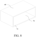
- FIG. 8 is a schematic perspective view of the cassette in FIG. 6 .
- the fragrance assembly 14 includes a cassette 60 fixed to the box 12.
- the cassette includes a receiving cavity 70 that receives at least part of the fragrance container 56 and an entry/exit portion 72 in communication with the receiving cavity 70.
- the fragrance container 56 may enter and exit the receiving cavity 70 through the entry/exit portion 72.
- the fragrance container 56 can be mounted.
- the cassette 60 may be in the shape of a cuboid.
- the receiving cavity 70 may correspond to a shape, a structure, and a size of the fragrance container 56 to receive the fragrance container 56.
- the entry/exit portion 72 may be an opening allowing the fragrance container 56 to pass through.
- the fragrance container 56 includes a lid 58, which may seal the entry/exit portion 72.
- the clothing handling device 10 can realize a compact structure and a beautiful appearance.
- the lid 58 may partially protrude into the entry/exit portion 72, abuts against an inner wall of the fragrance container 56, and covers an outer end surface of the entry/exit portion 72, so as to seal the entry/exit portion 72. In this way, a separate lid is omitted for the cassette 60, and the opening of the entry/exit portion 72 is covered, so that the clothing handling device 10 realizes a compact structure and a beautiful appearance.
- the fragrance container 56 includes a lid 58, which includes a handle portion 74 protruding from the cassette 60.
- the fragrance container 56 can be conveniently placed into the cassette 60 and taken out from the cassette 60.
- the handle portion 74 may be an edge portion of the lid 58 protruding from the cassette 60. When the fragrance container 56 needs to be placed into the cassette 60 or taken out from the cassette 60, a force may be applied to the handle portion 74.
- the cassette 60 includes an opening 62 arranged opposite to the entry/exit portion 72.
- the opening 62 may be in communication with the inside of the clothing handling device 10, to release the fragrance inside the clothing handling device 10.
- the entry/exit portion 72 may be in communication with the outside of the clothing handling device 10, to mount and replace the fragrance container 56.
- the fragrance container 56 includes a leaking portion 54, which may leak the fragrance through the opening 62.
- the leaking portion 54 may be exposed in the opening 62 and/or outside the opening 62.
- the fragrance leaking through the leaking portion 54 may be released to the outside of the cassette 60 through the opening 62.
- the fragrance assembly 14 includes an operating element 18, which includes an operating portion 20 and a cap portion 22.
- the cap portion 22 may expose or cover the opening 62 with a movement of the operating portion 20 to release or block the fragrance leaking through the leaking portion 54. In this way, the fragrance can be conveniently unblocked/blocked.
- a gap 49 in fluid communication with the leaking portion 54 and the outside of the fragrance assembly 14 may be formed between the cap portion 22 and the cassette 60, and the fragrance can be released to the outside of the fragrance assembly 14 through the gap 49.
- the fragrance may be sealed in the fragrance assembly 14.
- the operating portion 20 may be arranged at a position that facilitates operation, to unblock/block the fragrance.
- the fragrance assembly 14 includes an operating element 18 arranged outside the cassette 60.
- a fragrance storage position and a control operation position are spaced apart from each other, so that a control operation is less likely to be subjected to spatial and directional constraints.
- the operating element 18 may be controlled to operate outside the cassette 60 where the fragrance is stored, so that the control operation is less likely to be subjected to spatial and directional constraints.
- the fragrance assembly 14 includes an operating element 18 staggered with respect to the fragrance container 56 to release or block the fragrance in the fragrance container 56.
- the operating element 18 and the fragrance container 56 may be staggered with respect to each other in an up-down, front-rear, or left-right direction.
- the fragrance container 56 is less likely to be interfered by an operating element 18 that is mistakenly arranged during mounting and replacement.
- the operating element 18 is less likely to be interfered by a fragrance container 56 that is mistakenly arranged during operation.
- the fragrance assembly 14 includes an operating element 18 arranged separately from the fragrance container 56 to release or block the fragrance in the fragrance container 56.
- the operating element 18 may be fixed to the box 12 through welding or the like. When fragrance replacement or replenishment is required, only the fragrance container 56 instead of the entire fragrance assembly 14 needs to be taken out, and the operation is relatively simple. In addition, the operating element 18 is not disassembled a plurality of times, so that a possibility of damage is low.
Landscapes
- Engineering & Computer Science (AREA)
- Textile Engineering (AREA)
- Packaging Of Annular Or Rod-Shaped Articles, Wearing Apparel, Cassettes, Or The Like (AREA)
- Disinfection, Sterilisation Or Deodorisation Of Air (AREA)
Abstract
Description
- The present invention relates to the field of clothing handling technologies, and in particular, to a clothing handling device.
- Fragrance products of some existing clothing handling devices directly contact clothing, which may cause stains on the clothing, or a concentration cannot be well controlled and unblocking/blocking of a fragrance is inconvenient.
- In addition, although fragrance products of some other clothing handling devices do not directly contact the clothing, shortcomings such as the inconvenient unblocking/blocking of a fragrance still exist.
- Therefore, improvements are required.
- The present invention is intended to resolve at least one of the above problems.
- Embodiments of the present invention relate to a clothing handling device, including a box and a fragrance assembly arranged in the box. The fragrance assembly includes an accommodating element and an operating element, and the operating element is configured to release or block a fragrance in the accommodating element.
- Embodiments of this application can realize convenient unblocking/blocking of the fragrance.
- Optionally, the operating element and the accommodating element are stacked in a first direction and a second direction different from each other.
- In this way, the convenient unblocking/blocking of the fragrance and effective space utilization can be realized.
- Optionally, the operating element includes an operating portion and a cap portion linked with the operating portion, and the cap portion releases or blocks the fragrance with a movement of the operating portion.
- In this way, the convenient unblocking/blocking of the fragrance can be realized.
- Optionally, the operating portion is staggered with respect to the accommodating element in a first direction, and the cap portion and the accommodating element are movable relative to each other in a second direction different from the first direction.
- In this way, the convenient unblocking/blocking of the fragrance and effective space utilization can be realized.
- Optionally, the operating element includes an actuating member configured to cause the operating portion and/or the cap portion to move.
- In this way, the operating portion and/or the cap portion can move to unblock/block the fragrance.
- Optionally, the actuating member includes a linkage shaft connected to the operating portion and an elastic linkage member corresponding to the linkage shaft.
- In this way, the elastic linkage member can drive the operating portion to move through the linkage shaft.
- Optionally, the actuating member includes a stop shaft and an elastic stop member corresponding to the stop shaft, one of the stop shaft and the linkage shaft includes a bump, and the other includes a guiding surface and a groove corresponding to the bump.
- In this way, the operating portion and/or the cap portion can move and stop at a specific position. Optionally, the guiding surface and the groove are arranged adjacent to and spaced apart from each other.
- In this way, the operating portion and/or the cap portion can move and stop at a specific position.
- Optionally, the guiding surface is an inclined surface and is configured in such a way that the bump moves along the guiding surface into the groove when the operating portion drives the linkage shaft to move axially.
- In this way, the operating portion and the linkage shaft can smoothly move and reach a stop position. Optionally, a plurality of operating portions and a plurality of cap portions are respectively arranged.
- In this way, a fragrance type and concentration can be adjusted.
- Optionally, the operating portions and the cap portions have the same size or different sizes. In this way, the fragrance concentration and type can be adjusted.
- Optionally, the operating element includes a closing portion, a closing linkage shaft linked with the closing portion, and an elastic closing member corresponding to the closing linkage shaft. One of the closing linkage shaft and the stop shaft includes a closing bump, and the other includes a closing guiding surface corresponding to the closing bump.
- In this way, the fragrance can be blocked.
- Optionally, the closing guiding surface is an inclined plane and is configured in such a way that the closing bump drives the stop shaft to move axially when the closing portion drives the closing linkage shaft to move axially, so that the bump is disengaged from the groove and forms contact fit with the guiding surface.
- In this way, the fragrance can be smoothly blocked.
- Optionally, the operating element includes a receiving portion, and the operating portion, the cap portion, and the closing portion are at least partially located outside the receiving portion.
- In this way, the operating element can be operated conveniently.
- Optionally, the accommodating element includes an accommodating portion and a leaking portion, and the cap portion and the leaking portion are movable relative to each other to release or block the fragrance in the accommodating portion.
- In this way, the convenient unblocking/blocking of the fragrance can be realized.
- Optionally, the accommodating element includes a replaceable fragrance container including the accommodating portion, the leaking portion, and a lid.
- In this way, the fragrance can be conveniently replaced and replenished.
- Optionally, the accommodating element includes a cassette fixed to the box. The fragrance container is at least partially received in the cassette, the cassette includes an opening corresponding to the leaking portion, and the cap portion is configured to expose or cover the opening.
- In this way, the fragrance container can be mounted and the fragrance can be released or blocked.
- Optionally, the cassette includes a plurality of openings, and a plurality of operating portions and a plurality of cap portions are respectively arranged. Quantities of the operating portions and the cap portions respectively correspond to a quantity of the openings.
- In this way, the fragrance can be more flexibly unblocked/blocked and adjusted.
- Optionally, an air circulation area of at least one of the openings is different from those of the other openings.
- In this way, the fragrance concentration can be adjusted.
- Optionally, the clothing handling device includes a clothing handling chamber and an airflow passage in fluid communication with the clothing handling chamber. A part of the fragrance assembly is exposed in the airflow passage.
- In this way, fragrance can be applied to clothing in the clothing handling chamber through the fragrance assembly and the airflow passage.
- Optionally, the clothing handling device includes a clothing handling chamber. The leaking portion contacts circulating air passing through the clothing handling chamber after the cap portion leaves the leaking portion.
- In this way, the fragrance can be released through the leaking portion and the circulating air.
- Optionally, a plurality of leaking portions are arranged on the accommodating element, and a cross-sectional area of at least one of the leaking portions exposed to the circulating air is different from those of the other leaking portions.
- In this way, a concentration of the fragrance released through the leaking portion can be adjusted.
- Optionally, a plurality of leaking portions are arranged on the accommodating element, and a plurality of operating portions and a plurality of cap portions are respectively arranged. Quantities of the operating portions and the cap portions respectively correspond to a quantity of the leaking portions.
- In this way, the fragrance released through the leaking portion can be more flexibly adjusted. Optionally, each of the leaking portions includes a plug made of a porous medium.
- In this way, the fragrance can be released through the leaking portion.
- The technical solutions of the above embodiments may be combined arbitrarily if allowed. The present invention is further described below in combination with the drawings. The same and similar labels may be used in the drawings to indicate same and similar components, shapes, structures, characteristics, and the like in different embodiments, and may description of the same and similar components, shapes, structures, characteristics, effects, and the like in different embodiments and existing in prior art.
-
FIG. 1 is a schematic front view of a clothing handling device according to an aspect of embodiments of the present invention. -
FIG. 2 is a partial schematic cross-sectional view of a fragrance assembly of the clothing handling device inFIG. 1 . -
FIG. 3 is a schematic top view of an operating element of the fragrance assembly inFIG. 2 . -
FIG. 4 is another schematic top view similar toFIG. 3 . -
FIG. 5 is another partial schematic cross-sectional view similar toFIG. 2 . -
FIG. 6 is a partial schematic cross-sectional view of a cassette of the fragrance assembly inFIG. 5 . -
FIG. 7 is a partial schematic cross-sectional view of an accommodating element of the fragrance assembly inFIG. 5 . -
FIG. 8 is a schematic perspective view of the cassette inFIG. 6 . -
FIG. 1 is a schematic front view of a clothing handling device according to an aspect of embodiments of the present invention. A shown inFIG. 1 , the aspect of the embodiments of the present invention relates to aclothing handling device 10, including abox 12 and afragrance assembly 14 arranged in thebox 12. -
FIG. 2 is a partial schematic cross-sectional view of a fragrance assembly of the clothing handling device inFIG. 1 . Referring toFIG. 2 , thefragrance assembly 14 includes anaccommodating element 16 and anoperating element 18. The operatingelement 18 is configured to release or block a fragrance in theaccommodating element 16. - Embodiments of this application can realize convenient unblocking/blocking of the fragrance.
- For example, the
fragrance assembly 14 is arranged in thebox 12 to apply the fragrance to the clothing in thebox 12. The fragrance is accommodated in theaccommodating element 16 to reduce or avoid a possibility of direct contact between the fragrance and the clothing. The fragrance in theaccommodating element 16 may be released or blocked through the operatingelement 18, which is less likely to be subjected to spatial and structural constraint compared with directly releasing or blocking the fragrance through theaccommodating element 16. Therefore, the operation is more convenient. - Optionally, the operating
element 18 and theaccommodating element 16 are stacked in a first direction and a second direction different from each other. - In this way, the convenient unblocking/blocking of the fragrance and effective space utilization can be realized.
- The operating
element 18 and theaccommodating element 16 may include parts stacked in the first direction X and parts stacked in the second direction Y respectively, so that thefragrance assembly 14 is less likely to be oversized in a single direction, and the fragrance may be unblocked/blocked in a direction that facilitates operation, which is less likely to be subjected to spatial and structural constraints. - The terms "first" and "second" herein are not intended to represent a priority, a significance, and the like, but to help distinguish between directions, shapes, structures, elements, and the like modified by them.
- Optionally, the operating
element 18 includes an operatingportion 20 and acap portion 22 linked with the operatingportion 20, and thecap portion 22 may release or block the fragrance with a movement of the operatingportion 20. In this way, the convenient unblocking/blocking of the fragrance can be realized. - The operating
portion 20 and thecap portion 22 may be respectively arranged at a position that facilitates operation and a position that does not facilitate operation. For example, the operatingportion 20 may be arranged outside thefragrance assembly 14 and thebox 12 to facilitate operation, and thecap portion 22 may be arranged inside thefragrance assembly 14 and thebox 12 to facilitate the release of the fragrance inside. - For positions and relationships represented by the terms "inside", "outside", "front", "rear", "up", "down", "left", "right", "top", and "bottom" herein, refer to the drawings, or the positions and relationships may correspond to positions and relationships during actual use of the
clothing handling device 10. - Optionally, the operating
portion 20 is staggered with respect to theaccommodating element 16 in a first direction, and thecap portion 22 and theaccommodating element 16 are movable relative to each other in a second direction Y different from the first direction X. - In this way, the convenient unblocking/blocking of the fragrance and effective space utilization can be realized.
- For example, the operating
portion 20 may be arranged above or below theaccommodating element 16, and thecap portion 22 and theaccommodating element 16 are movable relative to each other in a front-rear direction. Thecap portion 22 may be arranged at an upper rear position or a lower rear position of the operatingportion 20. -
FIG. 3 is a schematic top view of the operating element inFIG. 2 .FIG. 4 is another schematic top view similar toFIG. 3 . As shown inFIG. 3 andFIG. 4 , optionally, the operatingelement 18 includes an actuatingmember 24 configured to cause the operatingportion 20 and/or thecap portion 22 to move. - In this way, the operating
portion 20 and/or thecap portion 22 can move to unblock/block the fragrance. - Referring to
FIG. 3 , the actuatingmember 24 can drive thecap portion 22 to move to release the fragrance when the operatingportion 20 is driven to move by a force. As shown inFIG. 2 andFIG. 4 , the actuatingmember 24 can further drive the operatingportion 20 and thecap portion 22 to return to an initial position to block the fragrance. - Optionally, the actuating
member 24 includes alinkage shaft 26 connected to the operatingportion 20 and anelastic linkage member 28 corresponding to thelinkage shaft 26. - In this way, the
elastic linkage member 28 can drive the operatingportion 20 to move through thelinkage shaft 26. - When the operating
portion 20 is driven to move by a force, thecap portion 22 can be driven to move through thelinkage shaft 26 to release the fragrance. At the same time, theelastic linkage member 28 accumulates elastic potential energy with the movement of thelinkage shaft 26. Thereafter, theelastic linkage member 28 can drive, through the elastic potential energy, thelinkage shaft 26, the operatingportion 20, and thecap portion 22 to return to the initial positions to block the fragrance. - Optionally, the actuating
member 24 includes astop shaft 30 and anelastic stop member 32 corresponding to thestop shaft 30, one of thestop shaft 30 and thelinkage shaft 26 includes abump 34, and the other includes a guidingsurface 36 and agroove 38 corresponding to thebump 34. - In this way, the operating
portion 20 and/or thecap portion 22 can move and stop at a specific position. - When the operating
portion 20 is driven to move by a force, thebump 34 can move along the guidingsurface 36 and then enter thegroove 38, to position the operatingportion 20 and thecap portion 22 at the corresponding position. Theelastic stop member 32 may accumulate elastic potential energy with the movement of thestop shaft 30, and may drive, through the elastic potential energy, thestop shaft 30 to move. - The
bump 34 may be arranged between the operatingportion 20 and theelastic linkage member 28. Theelastic linkage member 28 may be arranged between thebump 34 and thecap portion 22. - Optionally, the guiding
surface 36 and thegroove 38 are arranged adjacent to and spaced apart from each other. - In this way, the operating
portion 20 and/or thecap portion 22 can move and stop at a specific position. - When the operating
portion 20 is driven by a force, thebump 34 can move along the guidingsurface 36 and stop after entering thegroove 38, and thecap portion 22 moves and stops accordingly. - Optionally, the guiding
surface 36 is an inclined surface and is configured in such a way that thebump 34 moves along the guidingsurface 36 into thegroove 38 when the operatingportion 20 drives thelinkage shaft 26 to move axially. - In this way, the operating
portion 20 and thelinkage shaft 26 can smoothly move and reach a stop position. - The guiding
surface 36 may be inclined toward thegroove 38, so that thebump 34 can move along the guidingsurface 36 into thegroove 38. - Optionally, a plurality of operating
portions 20 andcap portions 22 are respectively arranged. In this way, a fragrance type and concentration can be adjusted. - The operating
portions 20 and thecap portions 22 may respectively correspond to different fragrance types and concentrations to adjust the fragrance types and concentrations correspondingly. - Optionally, the operating
portions 20 and thecap portions 22 have the same size or different sizes. In this way, the fragrance concentration and type can be adjusted. - In some embodiments, the operating
portions 20 and thecap portions 22 having the same size may correspond to different fragrance types and concentrations. In some embodiments, alarger operating portion 20 and alarger cap portion 22 may correspond to a higher fragrance concentration, and a smaller operating portion and a smaller cap portion may correspond to a lower fragrance concentration, or vice versa. - In some embodiments, as shown in the figure, the operating
portions 20 may include alarge operating portion 17, amedium operating portion 19, and asmall operating portion 21, and thecap portions 22 may include alarge cap portion 23, amedium cap portion 25, and asmall cap portion 27, which may correspond to high, medium, and low fragrance concentrations. - Optionally, the operating
element 18 includes a closingportion 40, aclosing linkage shaft 42 linked with the closingportion 40, and anelastic closing member 44 corresponding to theclosing linkage shaft 42, one of theclosing linkage shaft 42 and thestop shaft 30 includes aclosing bump 46, and the other includes aclosing guiding surface 48 corresponding to theclosing bump 46. - In this way, the fragrance can be blocked.
- When the closing
portion 40 is driven to move by a force, theclosing bump 46 can move along theclosing guiding surface 48, and push thestop shaft 30, theelastic stop member 32, and theelastic closing member 44 to move, so that thebump 34 can be disengaged from thegroove 38 and contact the guidingsurface 36, and theelastic linkage member 28 can drive, through the elastic potential energy, the operatingportion 20 and thecap portion 22 to return to the initial position shown inFIG. 4 to block the fragrance. Then theelastic closing member 44 and theelastic stop member 32 can drive, through the elastic potential energy, the closingportion 40 and thestop shaft 30 to return to the initial position shown inFIG. 4 . - A distance by which the
closing bump 46 moves along theclosing guiding surface 48 may be greater than a distance by which thebump 34 moves along the guidingsurface 36. - The
closing guiding surface 48 may be arranged on a free end of thestop shaft 30, and theelastic stop member 32 may be arranged on an other end of thestop shaft 30. The guidingsurface 36 and thegroove 38 may be arranged between theclosing guiding surface 48 and theelastic stop member 32. - Optionally, the
closing guiding surface 48 is an inclined plane and is configured in such a way that theclosing bump 46 drives thestop shaft 30 to move axially when the closingportion 40 drives the closinglinkage shaft 42 to move axially, so that thebump 34 is disengaged from thegroove 38 and forms contact fit with the guidingsurface 36. - In this way, the fragrance can be smoothly blocked.
- The
closing guiding surface 48 may be inclined toward theclosing bump 46, so that thestop shaft 30 can be pushed to move leftward when the closingportion 40 is driven to be moved rearward by a force, during which theelastic closing member 44 and theelastic stop member 32 can accumulate elastic potential energy. Then theelastic closing member 44 can drive, through the elastic potential energy, the closinglinkage shaft 42 and the closingportion 40 to move forward, and thestop shaft 30 may be driven to move rightward by theelastic stop member 32. - A slope of the
closing guiding surface 48 may be less than a slope of the guidingsurface 36. - Optionally, the operating
element 18 includes a receivingportion 50, and the operatingportion 20, thecap portion 22, and the closingportion 40 are at least partially located outside the receivingportion 50. - In this way, the operating
element 18 can be operated conveniently. -
FIG. 5 is another partial schematic cross-sectional view similar toFIG. 2 . Referring toFIG. 5 , the receivingportion 50 may be substantially in the shape of a cassette including atop wall 51, abottom wall 53, afront wall 55, arear wall 57, aleft wall 59, and aright wall 61. Thetop wall 51 may be disassembled. Thetop wall 51 is omitted inFIG. 3 andFIG. 4 . The operatingportion 20 and the closingportion 40 may protrude from thefront wall 55. Thecap portion 22 may protrude from therear wall 57. Theelastic stop member 32 may abut against an inner side of theleft wall 59. Thestop shaft 30 may extend toward theright wall 61 from theelastic stop member 32. - The
elastic linkage member 28 and theelastic closing member 44 may abut against an inner side of therear wall 57. Thelinkage shaft 26 may extend through thefront wall 55 and therear wall 57, and include alinkage squeezing portion 63 that can squeeze theelastic linkage member 28 toward therear wall 57. The closinglinkage shaft 42 may extend between thefront wall 55 and therear wall 57, and include aclosing squeezing portion 65 that can squeeze theelastic closing member 44 toward therear wall 57. - Referring to
FIG. 2 andFIG. 5 , optionally, theaccommodating element 16 includes anaccommodating portion 52 and a leakingportion 54, and thecap portion 22 and the leakingportion 54 are movable relative to each other to release or block the fragrance in theaccommodating portion 52. - In this way, the convenient unblocking/blocking of the fragrance can be realized.
- As shown in
FIG. 2 , when thecap portion 22 covers the leakingportion 54, the fragrance in theaccommodating portion 52 cannot be released outward. Referring toFIG. 5 , when thecap portion 22 exposes the leakingportion 54, the fragrance in theaccommodating portion 52 can be released through agap 49 in fluid communication with the leakingportion 54. - Optionally, the
accommodating element 16 includes areplaceable fragrance container 56 including theaccommodating portion 52, the leakingportion 54, and alid 58. - In this way, the fragrance can be conveniently replaced and replenished.
- When fragrance replacement or replenishment is required, the
fragrance container 56 may be taken out and another fragrance container with a fragrance may be placed, to replace or replenish the fragrance for thefragrance assembly 14, or thelid 58 may be opened, and the fragrance in theaccommodating portion 52 of thefragrance container 56 is replaced or replenished and then thefragrance container 56 is replaced back. - Optionally, the
accommodating element 16 includes acassette 60 fixed to thebox 12. Thefragrance container 56 is at least partially received in the cassette, thecassette 60 includes anopening 62 corresponding to the leakingportion 54, and thecap portion 22 is configured to expose or cover theopening 62. - In this way, the
fragrance container 56 can be mounted and the fragrance can be released or blocked. - The
cassette 60 may be fixed to thebox 12 through welding or the like. The leakingportion 54 and theopening 62 are arranged adjacent and opposite to each other, may protrude into theopening 62, and may extend through theopening 62. Referring toFIG. 5 , when thecap portion 22 moves away to expose theopening 62, the fragrance can be released outward through thegap 49 between the leakingportion 54, theopening 62, and thecap portion 22 and theaccommodating element 16. As shown inFIG. 2 , when thecap portion 22 approaches to cover theopening 62, the fragrance is sealed in thefragrance assembly 14 and is in a blocked state. -
FIG. 6 is a partial schematic cross-sectional view of the cassette of the fragrance assembly inFIG. 5 . Referring toFIG. 4 ,FIG. 5 , andFIG. 6 , optionally, thecassette 60 includes a plurality ofopenings 62, and a plurality of operatingportions 20 and a plurality ofcap portions 22 are respectively arranged. Quantities of the operating portions and the cap portions respectively correspond to a quantity of theopenings 62. In this way, the fragrance can be more flexibly unblocked/blocked and adjusted. - Each of the operating
portions 20 may drive a corresponding one of thecap portions 22 to move, so that a corresponding one of theopenings 62 can be exposed or covered. When it is necessary to block the fragrance and adjust the fragrance concentration and type, acorresponding operating portion 20 may be operated. - Optionally, an air circulation area of at least one of the
openings 62 is different from those of theother openings 62. - In this way, the fragrance concentration can be adjusted.
- The air circulation area of the
opening 62 may correspond to an opening area thereof. Anopening 62 having a larger air circulation area may correspond to a higher fragrance concentration, and anopening 62 having a smaller air circulation area may correspond to a lower fragrance concentration, or vice versa. - The
clothing handling device 10 may be a washing and drying machine or a drying machine. Still referring toFIG. 1 , optionally, theclothing handling device 10 includes aclothing handling chamber 64 and anairflow passage 66 in fluid communication with theclothing handling chamber 64. A part of thefragrance assembly 14 may be exposed in theairflow passage 66. - In this way, fragrance can be applied to clothing in the
clothing handling chamber 64 through thefragrance assembly 14 and theairflow passage 66. - The
fragrance assembly 14 may be arranged at a front of thebox 12 and below theclothing handling chamber 64. Theclothing handling device 10 may perform handling such as washing and drying on the clothing in theclothing handling chamber 64. During the drying of the clothing in theclothing handling chamber 64 in theclothing handling device 10, the fragrance in thefragrance assembly 14 can enter theclothing handling chamber 64 through theairflow passage 66, which is absorbed by the clothing. After air circulation for a specific period, the function of adding fragrance to the clothing can be realized. - Optionally, the
clothing handling device 10 includes aclothing handling chamber 64. The leakingportion 54 contacts circulating air passing through theclothing handling chamber 64 after thecap portion 22 leaves the leakingportion 54. - In this way, the fragrance can be released through the leaking
portion 54 and the circulating air. - When the leaking
portion 54 contacts the circulating air passing through theclothing handling chamber 64, the fragrance may be mixed with the circulating air through the leakingportion 54, and then enter theclothing handling chamber 64 with the circulating air, which can be absorbed by the clothing in theclothing handling chamber 64. After air circulation for a specific period, the function of adding fragrance to the clothing can be realized. -
FIG. 7 is a partial schematic cross-sectional view of the accommodating element of the fragrance assembly inFIG. 5 . Referring toFIG. 7 , optionally, a plurality of leakingportions 54 are arranged on theaccommodating element 16, and a cross-sectional area of at least one of the leakingportions 54 exposed to the circulating air is different from those of the other leakingportions 54. - In this way, a concentration of the fragrance released through the leaking
portion 54 can be adjusted. - A leaking
portion 54 with a larger cross-sectional area exposed to the circulating air may correspond to a higher fragrance concentration, a leakingportion 54 with a smaller cross-sectional area exposed to the circulating air may correspond to a lower fragrance concentration, and leakingportions 54 with the same cross-sectional area exposed to the circulating air may correspond to the same fragrance concentration. - Referring to
FIG. 4 ,FIG. 5 , andFIG. 7 , optionally, a plurality of leakingportions 54 are arranged on theaccommodating element 16, and a plurality of operatingportions 20 and a plurality ofcap portions 22 are arranged. Quantities of the operating portions and the cap portions respectively correspond to a quantity of the leakingportions 54. - In this way, the fragrance released through the leaking
portion 54 can be more flexibly adjusted. - Each of the operating
portions 20 may drive a corresponding one of thecap portions 22 to move, so as to unblock or block the fragrance leaking from a corresponding one of the leakingportions 54. When it is necessary to unblock a fragrance and adjust a fragrance concentration and type, acorresponding operating portion 20 may be operated. - Optionally, each of the leaking
portions 54 includes a plug made of a porous medium. - In this way, the fragrance can be released through the leaking
portion 54. - The leaking
portion 54 can absorb a liquid fragrance through the gap. When the air contacts the leakingportion 54, the fragrance adsorbed through the gap of the leakingportion 54 can volatilize into the air. - Still referring to
FIG. 1 , an aspect of the embodiments of the present invention relates to aclothing handling device 10, including abox 12 and afragrance assembly 14 arranged in thebox 12. Thefragrance assembly 14 includes areplaceable fragrance container 56. - The embodiments of this application can realize convenient replacement of a fragrance.
- For example, the
fragrance assembly 14 is arranged in thebox 12 to apply the fragrance to the clothing in thebox 12. When fragrance replacement or replenishment is required, thefragrance container 56 may be taken out to replace or replenish the fragrance for thefragrance container 56, and then the fragrance container is replaced back, or a replacedfragrance container 56 may be placed. - Still referring to
FIG. 5 , optionally, thefragrance container 56 includes anaccommodating portion 52 and a leakingportion 54. In this way, a fragrance can be prevented from direct contact with the clothing and the concentration can be easily controlled. - The
accommodating portion 52 can accommodate the fragrance, and the leakingportion 54 can leak the fragrance in theaccommodating portion 52. A concentration of a fragrance applied may be adjusted by controlling the leakingportion 54. - Optionally, the
fragrance container 56 includes alid 58 arranged opposite to the leakingportion 54 and configured to seal theaccommodating portion 52 with the leaking portion. - In this way, the fragrance can be replaced or replenished for the
fragrance container 56. - When the fragrance needs to be replaced or replenished, the
lid 58 may be opened to add a different fragrance and the same fragrance to theaccommodating portion 52. The leakingportion 54 may be arranged in an inaccessible position such as an interior of theclothing handling device 10. Thelid 58 may be located in an accessible position such as an exterior of theclothing handling device 10. - Still referring to
FIG. 7 , optionally, thefragrance container 56 includes a plurality ofchambers 68. Each of thechambers 68 includes theaccommodating portion 52 and the leakingportion 54. - In this way, the fragrance concentration and type can be flexibly adjusted.
- As shown in
FIG. 7 , thefragrance container 56 may include threechambers 68. Each of thechambers 68 includes one accommodatingportion 52 and one leakingportion 54. Theaccommodating portion 52 may be in the shape of a cassette with openings on two opposite walls. The leakingportion 54 may fill the opening on one of the walls, such as the rear wall of theaccommodating portion 52. Thelid 58 may seal the opening on the other wall, such as the front wall of theaccommodating portion 52. A part of thelid 58 may protrude into theaccommodating portion 52 and contact an inner wall of theaccommodating portion 52, to seal theaccommodating portion 52, which enhances a binding force between the lid and the accommodating portion. - Optionally, an accommodating capacity of the
accommodating portion 52 of at least one of thechambers 68 is different from those of theaccommodating portions 52 of theother chambers 68. - In this way, the fragrance concentration and type can be adjusted.
- As shown in the figure, the three
chambers 68 may bechambers large operating portion 17, themedium operating portion 19, and thesmall operating portion 21, thelarge cap portion 23, themedium cap portion 25, and thesmall cap portion 27, and the high-concentration fragrance, the medium-concentration fragrance, and the low-concentration fragrance. When the high-concentration fragrance, the medium-concentration fragrance, or the low-concentration fragrance is required, the correspondinglarge cap portion 23,medium cap portion 25, orsmall cap portion 27 may be driven to move by thelarge operating portion 17, themedium operating portion 19, or thesmall operating portion 21, so as to release the fragrance in the correspondinglarge chamber 69,medium chamber 71, orsmall chamber 73. - In some other embodiments, the
large chamber 69, themedium chamber 71, and thesmall chamber 73 may respectively correspond to three different types of fragrances. When a fragrance of a specific type is required, the fragrance in the corresponding one of thechambers - Optionally, a fragrance type of the
accommodating portion 52 of at least one of thechambers 68 is different from those of theaccommodating portions 52 of theother chambers 68. - In this way, the fragrance type can be adjusted.
- The fragrance in the
corresponding chamber 68 may be released according to a required fragrance type to adjust the fragrance type. - Optionally, an area of the leaking
portion 54 of at least one of thechambers 68 that may be exposed to the outside air is different from those of the leakingportions 54 of theother chambers 68. - In this way, the fragrance concentration can be adjusted.
- As shown in the figure, the leaking
portions 54 may include alarge leaking portion 41, amedium leaking portion 43, and a small leakingportion 45, which respectively correspond to thelarge chamber 69, themedium chamber 71, and thesmall chamber 73. - For example, when a high-concentration fragrance is required, the
large chamber 69 corresponding to thelarge leaking portion 41 may be selected. When a low-concentration fragrance is required, thesmall chamber 73 corresponding to the small leakingportion 45 may be selected. For example, when a medium-concentration fragrance is required, themedium chamber 71 corresponding to themedium leaking portion 43 may be selected. - Optionally, the leaking
portion 54 is made of a material that allows a liquid or a gas to penetrate. In this way, the fragrance can be released. - For example, the leaking
portion 54 can adsorb the liquid fragrance in theaccommodating portion 52, so that the adsorbed liquid fragrance can volatilize and be mixed with the air, and flow with the air when the fragrance contacts the outside air. -
FIG. 8 is a schematic perspective view of the cassette inFIG. 6 . Referring toFIG. 8 , optionally, thefragrance assembly 14 includes acassette 60 fixed to thebox 12. The cassette includes a receivingcavity 70 that receives at least part of thefragrance container 56 and an entry/exit portion 72 in communication with the receivingcavity 70. Thefragrance container 56 may enter and exit the receivingcavity 70 through the entry/exit portion 72. - In this way, the
fragrance container 56 can be mounted. - The
cassette 60 may be in the shape of a cuboid. The receivingcavity 70 may correspond to a shape, a structure, and a size of thefragrance container 56 to receive thefragrance container 56. The entry/exit portion 72 may be an opening allowing thefragrance container 56 to pass through. - Still referring to
FIG. 7 , optionally, thefragrance container 56 includes alid 58, which may seal the entry/exit portion 72. - In this way, the
clothing handling device 10 can realize a compact structure and a beautiful appearance. - The
lid 58 may partially protrude into the entry/exit portion 72, abuts against an inner wall of thefragrance container 56, and covers an outer end surface of the entry/exit portion 72, so as to seal the entry/exit portion 72. In this way, a separate lid is omitted for thecassette 60, and the opening of the entry/exit portion 72 is covered, so that theclothing handling device 10 realizes a compact structure and a beautiful appearance. - Optionally, the
fragrance container 56 includes alid 58, which includes ahandle portion 74 protruding from thecassette 60. - In this way, the
fragrance container 56 can be conveniently placed into thecassette 60 and taken out from thecassette 60. - The
handle portion 74 may be an edge portion of thelid 58 protruding from thecassette 60. When thefragrance container 56 needs to be placed into thecassette 60 or taken out from thecassette 60, a force may be applied to thehandle portion 74. - Optionally, the
cassette 60 includes anopening 62 arranged opposite to the entry/exit portion 72. - In this way, the fragrance can be released inside the
clothing handling device 10. - The
opening 62 may be in communication with the inside of theclothing handling device 10, to release the fragrance inside theclothing handling device 10. The entry/exit portion 72 may be in communication with the outside of theclothing handling device 10, to mount and replace thefragrance container 56. - Optionally, the
fragrance container 56 includes a leakingportion 54, which may leak the fragrance through theopening 62. - In this way, the release of a fragrance can be controlled.
- The leaking
portion 54 may be exposed in theopening 62 and/or outside theopening 62. The fragrance leaking through the leakingportion 54 may be released to the outside of thecassette 60 through theopening 62. - Still referring
FIG. 2 andFIG. 5 , optionally, thefragrance assembly 14 includes anoperating element 18, which includes an operatingportion 20 and acap portion 22. Thecap portion 22 may expose or cover theopening 62 with a movement of the operatingportion 20 to release or block the fragrance leaking through the leakingportion 54. In this way, the fragrance can be conveniently unblocked/blocked. - When the
cap portion 22 exposes theopening 62, agap 49 in fluid communication with the leakingportion 54 and the outside of thefragrance assembly 14 may be formed between thecap portion 22 and thecassette 60, and the fragrance can be released to the outside of thefragrance assembly 14 through thegap 49. When thecap portion 22 covers theopening 62, the fragrance may be sealed in thefragrance assembly 14. The operatingportion 20 may be arranged at a position that facilitates operation, to unblock/block the fragrance. - Optionally, the
fragrance assembly 14 includes anoperating element 18 arranged outside thecassette 60. - In this way, a fragrance storage position and a control operation position are spaced apart from each other, so that a control operation is less likely to be subjected to spatial and directional constraints.
- The operating
element 18 may be controlled to operate outside thecassette 60 where the fragrance is stored, so that the control operation is less likely to be subjected to spatial and directional constraints. - Optionally, the
fragrance assembly 14 includes anoperating element 18 staggered with respect to thefragrance container 56 to release or block the fragrance in thefragrance container 56. - In this way, the operating
element 18 and thefragrance container 56 are less likely to interfere with each other. - The operating
element 18 and thefragrance container 56 may be staggered with respect to each other in an up-down, front-rear, or left-right direction. - The
fragrance container 56 is less likely to be interfered by an operatingelement 18 that is mistakenly arranged during mounting and replacement. The operatingelement 18 is less likely to be interfered by afragrance container 56 that is mistakenly arranged during operation. - Optionally, the
fragrance assembly 14 includes anoperating element 18 arranged separately from thefragrance container 56 to release or block the fragrance in thefragrance container 56. - In this way, the
fragrance container 56 can be replaced. - The operating
element 18 may be fixed to thebox 12 through welding or the like. When fragrance replacement or replenishment is required, only thefragrance container 56 instead of theentire fragrance assembly 14 needs to be taken out, and the operation is relatively simple. In addition, the operatingelement 18 is not disassembled a plurality of times, so that a possibility of damage is low. - The specific implementations described above and shown in the drawings are merely used for describing the present invention, and are not the entirety of the present invention. Any form of changes made by a person of ordinary skill in the art to the present invention within the scope of the basic technical ideas of the present invention fall within the protection scope of the present invention.
Claims (24)
- A clothing handling device (10), characterized by comprising:a box (12); anda fragrance assembly (14), arranged in the box (12), wherein the fragrance assembly (14) comprises an accommodating element (16) and an operating element (18), and the operating element (18) is configured to release or block a fragrance in the accommodating element (16).
- The clothing handling device (10) according to claim 1, characterized in that the operating element (18) and the accommodating element (16) are stacked in a first direction (X) and a second direction (Y) different from each other.
- The clothing handling device (10) according to claim 1, characterized in that the operating element (18) comprises an operating portion (20) and a cap portion (22) linked with the operating portion (20), wherein the cap portion (22) releases or blocks the fragrance with a movement of the operating portion (20).
- The clothing handling device (10) according to claim 3, characterized in that the operating portion (20) is staggered with respect to the accommodating element (16) in a first direction (X), and the cap portion (22) and the accommodating element (16) are movable relative to each other in a second direction (Y) different from the first direction (X).
- The clothing handling device (10) according to claim 3, characterized in that the operating element (18) comprises an actuating member (24) configured to cause the operating portion (20) and/or the cap portion (22) to move.
- The clothing handling device (10) according to claim 5, characterized in that the actuating member (24) comprises a linkage shaft (26) connected to the operating portion (20) and an elastic linkage member (28) corresponding to the linkage shaft (26).
- The clothing handling device (10) according to claim 6, characterized in that the actuating member (24) comprises a stop shaft (30) and an elastic stop member (32) corresponding to the stop shaft (30), wherein one of the stop shaft (30) and the linkage shaft (26) comprises a bump (34), and the other comprises a guiding surface (36) and a groove (38) corresponding to the bump (34).
- The clothing handling device (10) according to claim 7, characterized in that the guiding surface (36) and the groove (38) are arranged adjacent to and spaced apart from each other.
- The clothing handling device (10) according to claim 8, characterized in that the guiding surface (36) is an inclined surface and is configured in such a way that the bump (34) moves along the guiding surface (36) into the groove (38) when the operating portion (20) drives the linkage shaft (26) to move axially.
- The clothing handling device (10) according to claim 7, characterized in that a plurality of operating portions (20) and a plurality of cap portions (22) are respectively arranged.
- The clothing handling device (10) according to claim 10, characterized in that the operating portions (20) and the cap portions (22) have the same size or different sizes.
- The clothing handling device (10) according to claim 7, characterized in that the operating element (18) comprises a closing portion (40), a closing linkage shaft (42) linked with the closing portion (40), and an elastic closing member (44) corresponding to the closing linkage shaft (42), wherein one of the closing linkage shaft (42) and the stop shaft (30) comprises a closing bump (46), and the other comprises a closing guiding surface (48) corresponding to the closing bump (46).
- The clothing handling device (10) according to claim 12, characterized in that the closing guiding surface (48) is an inclined plane and is configured in such a way that the closing bump (46) drives the stop shaft (30) to move axially when the closing portion (40) drives the closing linkage shaft (42) to move axially, so that the bump (34) is disengaged from the groove (38) and forms contact fit with the guiding surface (36).
- The clothing handling device (10) according to claim 12, characterized in that the operating element (18) comprises a receiving portion (50), wherein the operating portion (20), the cap portion (22), and the closing portion (40) are at least partially located outside the receiving portion (50).
- The clothing handling device (10) according to claim 3, characterized in that the accommodating element (16) comprises an accommodating portion (52) and a leaking portion (54), wherein the cap portion (22) and the leaking portion (54) are movable relative to each other to release or block the fragrance in the accommodating portion (52).
- The clothing handling device (10) according to claim 15, characterized in that the accommodating element (16) comprises a replaceable fragrance container (56) comprising the accommodating portion (52), the leaking portion (54), and a lid (58).
- The clothing handling device (10) according to claim 16, characterized in that the accommodating element (16) comprises a cassette (60) fixed to the box (12), wherein the fragrance container (56) is at least partially received in the cassette, the cassette (60) comprises an opening (62) corresponding to the leaking portion (54), and the cap portion (22) is configured to expose or cover the opening (62).
- The clothing handling device (10) according to claim 17. characterized in that the cassette (60) comprises a plurality of openings (62), and a plurality of operating portions (20) and a plurality of cap portions (22) are respectively arranged, wherein quantities of the operating portions and the cap portions respectively correspond to a quantity of the openings (62).
- The clothing handling device (10) according to claim 18, characterized in that an air circulation area of at least one of the openings (62) is different from those of the other openings (62).
- The clothing handling device (10) according to claim 15, characterized by comprising a clothing handling chamber (64) and an airflow passage (66) in fluid communication with the clothing handling chamber (64), wherein a part of the fragrance assembly (14) is exposed in the airflow passage (66).
- The clothing handling device (10) according to claim 15, characterized by comprising a clothing handling chamber (64), wherein the leaking portion (54) contacts circulating air passing through the clothing handling chamber (64) after the cap portion (22) leaves the leaking portion (54).
- The clothing handling device (10) according to claim 21, characterized in that a plurality of leaking portions (54) are arranged on the accommodating element (16), and a cross-sectional area of at least one of the leaking portions (54) exposed to the circulating air is different from those of the other leaking portions (54).
- The clothing handling device (10) according to claim 15, characterized in that a plurality of leaking portions (54) are arranged on the accommodating element (16), and a plurality of operating portions (20) and a plurality of cap portions (22) are respectively arranged, wherein quantities of the operating portions and the cap portions respectively correspond to a quantity of the leaking portions (54).
- The clothing handling device (10) according to claim 15, characterized in that the leaking portion (54) comprises a plug made of a porous medium.
Applications Claiming Priority (1)
| Application Number | Priority Date | Filing Date | Title |
|---|---|---|---|
| CN202210356117.8A CN116856155A (en) | 2022-03-28 | 2022-03-28 | Clothes treating apparatus |
Publications (2)
| Publication Number | Publication Date |
|---|---|
| EP4253638A1 true EP4253638A1 (en) | 2023-10-04 |
| EP4253638B1 EP4253638B1 (en) | 2025-08-27 |
Family
ID=85704596
Family Applications (1)
| Application Number | Title | Priority Date | Filing Date |
|---|---|---|---|
| EP23162725.8A Active EP4253638B1 (en) | 2022-03-28 | 2023-03-17 | Clothing handling device |
Country Status (2)
| Country | Link |
|---|---|
| EP (1) | EP4253638B1 (en) |
| CN (1) | CN116856155A (en) |
Citations (3)
| Publication number | Priority date | Publication date | Assignee | Title |
|---|---|---|---|---|
| US20110138863A1 (en) * | 2008-09-08 | 2011-06-16 | Kim Kyeong-Hwan | Odor Supply Apparatus and Washing/Drying Machine Having the Same |
| DE102018120954A1 (en) * | 2018-08-28 | 2020-03-05 | Miele & Cie. Kg | Program controlled clothes dryer |
| US20210010184A1 (en) * | 2019-07-10 | 2021-01-14 | Haier Us Appliance Solutions, Inc. | Additive reservoir receptacle for an appliance |
-
2022
- 2022-03-28 CN CN202210356117.8A patent/CN116856155A/en active Pending
-
2023
- 2023-03-17 EP EP23162725.8A patent/EP4253638B1/en active Active
Patent Citations (3)
| Publication number | Priority date | Publication date | Assignee | Title |
|---|---|---|---|---|
| US20110138863A1 (en) * | 2008-09-08 | 2011-06-16 | Kim Kyeong-Hwan | Odor Supply Apparatus and Washing/Drying Machine Having the Same |
| DE102018120954A1 (en) * | 2018-08-28 | 2020-03-05 | Miele & Cie. Kg | Program controlled clothes dryer |
| US20210010184A1 (en) * | 2019-07-10 | 2021-01-14 | Haier Us Appliance Solutions, Inc. | Additive reservoir receptacle for an appliance |
Also Published As
| Publication number | Publication date |
|---|---|
| EP4253638B1 (en) | 2025-08-27 |
| CN116856155A (en) | 2023-10-10 |
Similar Documents
| Publication | Publication Date | Title |
|---|---|---|
| US11357381B2 (en) | Nozzle for cleaner | |
| EP4253637A1 (en) | Clothing handling device | |
| EP4253638B1 (en) | Clothing handling device | |
| US12402769B2 (en) | Wet-and-dry floor brush for vacuum cleaner | |
| KR0136962B1 (en) | Ink cartridge | |
| US20220304542A1 (en) | Drainer, Wet Mopping Device, And Wet-And-Dry Cleaning Head | |
| IT9045758A1 (en) | DISHWASHER WITH MULTI-DOSE DISPENSER OF POWDER DETERGENT | |
| US5493087A (en) | Operating unit for a key switch | |
| CN219462031U (en) | Aromatherapy seat | |
| KR102225142B1 (en) | Smart diffuser | |
| CN210182297U (en) | Waterproof ventilative shell and relay | |
| CN110544600B (en) | Waterproof breathable shell and relay | |
| KR20230077337A (en) | Dish Washer | |
| CN210871404U (en) | A put in device, door body group spare and dish washer for dish washer | |
| JP2023540774A (en) | pulsator type washing machine | |
| KR100617955B1 (en) | LPG Container Valve | |
| CN210673253U (en) | A put in device, door body group spare and dish washer for dish washer | |
| JPS6135121Y2 (en) | ||
| CN223830372U (en) | Multi-bin atomizer | |
| JPH0451760Y2 (en) | ||
| JPH04106329A (en) | Air conditioner | |
| CN117774547B (en) | Inkstone | |
| CN101219044B (en) | Movable cleaning product holder | |
| CN217865584U (en) | Multi-cavity food can | |
| CN116926934A (en) | Clothes treating apparatus |
Legal Events
| Date | Code | Title | Description |
|---|---|---|---|
| PUAI | Public reference made under article 153(3) epc to a published international application that has entered the european phase |
Free format text: ORIGINAL CODE: 0009012 |
|
| STAA | Information on the status of an ep patent application or granted ep patent |
Free format text: STATUS: THE APPLICATION HAS BEEN PUBLISHED |
|
| AK | Designated contracting states |
Kind code of ref document: A1 Designated state(s): AL AT BE BG CH CY CZ DE DK EE ES FI FR GB GR HR HU IE IS IT LI LT LU LV MC ME MK MT NL NO PL PT RO RS SE SI SK SM TR |
|
| STAA | Information on the status of an ep patent application or granted ep patent |
Free format text: STATUS: REQUEST FOR EXAMINATION WAS MADE |
|
| 17P | Request for examination filed |
Effective date: 20240404 |
|
| RBV | Designated contracting states (corrected) |
Designated state(s): AL AT BE BG CH CY CZ DE DK EE ES FI FR GB GR HR HU IE IS IT LI LT LU LV MC ME MK MT NL NO PL PT RO RS SE SI SK SM TR |
|
| GRAP | Despatch of communication of intention to grant a patent |
Free format text: ORIGINAL CODE: EPIDOSNIGR1 |
|
| STAA | Information on the status of an ep patent application or granted ep patent |
Free format text: STATUS: GRANT OF PATENT IS INTENDED |
|
| RIC1 | Information provided on ipc code assigned before grant |
Ipc: D06F 25/00 20060101ALN20250319BHEP Ipc: D06F 58/20 20060101AFI20250319BHEP |
|
| INTG | Intention to grant announced |
Effective date: 20250402 |
|
| GRAS | Grant fee paid |
Free format text: ORIGINAL CODE: EPIDOSNIGR3 |
|
| GRAA | (expected) grant |
Free format text: ORIGINAL CODE: 0009210 |
|
| STAA | Information on the status of an ep patent application or granted ep patent |
Free format text: STATUS: THE PATENT HAS BEEN GRANTED |
|
| AK | Designated contracting states |
Kind code of ref document: B1 Designated state(s): AL AT BE BG CH CY CZ DE DK EE ES FI FR GB GR HR HU IE IS IT LI LT LU LV MC ME MK MT NL NO PL PT RO RS SE SI SK SM TR |
|
| REG | Reference to a national code |
Ref country code: CH Ref legal event code: EP |
|
| REG | Reference to a national code |
Ref country code: DE Ref legal event code: R096 Ref document number: 602023005985 Country of ref document: DE |
|
| REG | Reference to a national code |
Ref country code: IE Ref legal event code: FG4D |
|
| REG | Reference to a national code |
Ref country code: NL Ref legal event code: MP Effective date: 20250827 |
|
| PG25 | Lapsed in a contracting state [announced via postgrant information from national office to epo] |
Ref country code: IS Free format text: LAPSE BECAUSE OF FAILURE TO SUBMIT A TRANSLATION OF THE DESCRIPTION OR TO PAY THE FEE WITHIN THE PRESCRIBED TIME-LIMIT Effective date: 20251227 |
|
| PG25 | Lapsed in a contracting state [announced via postgrant information from national office to epo] |
Ref country code: NO Free format text: LAPSE BECAUSE OF FAILURE TO SUBMIT A TRANSLATION OF THE DESCRIPTION OR TO PAY THE FEE WITHIN THE PRESCRIBED TIME-LIMIT Effective date: 20251127 |
|
| REG | Reference to a national code |
Ref country code: LT Ref legal event code: MG9D |
|
| PG25 | Lapsed in a contracting state [announced via postgrant information from national office to epo] |
Ref country code: PT Free format text: LAPSE BECAUSE OF FAILURE TO SUBMIT A TRANSLATION OF THE DESCRIPTION OR TO PAY THE FEE WITHIN THE PRESCRIBED TIME-LIMIT Effective date: 20251229 |
|
| PG25 | Lapsed in a contracting state [announced via postgrant information from national office to epo] |
Ref country code: FI Free format text: LAPSE BECAUSE OF FAILURE TO SUBMIT A TRANSLATION OF THE DESCRIPTION OR TO PAY THE FEE WITHIN THE PRESCRIBED TIME-LIMIT Effective date: 20250827 |
|
| PG25 | Lapsed in a contracting state [announced via postgrant information from national office to epo] |
Ref country code: HR Free format text: LAPSE BECAUSE OF FAILURE TO SUBMIT A TRANSLATION OF THE DESCRIPTION OR TO PAY THE FEE WITHIN THE PRESCRIBED TIME-LIMIT Effective date: 20250827 Ref country code: NL Free format text: LAPSE BECAUSE OF FAILURE TO SUBMIT A TRANSLATION OF THE DESCRIPTION OR TO PAY THE FEE WITHIN THE PRESCRIBED TIME-LIMIT Effective date: 20250827 |
|
| PG25 | Lapsed in a contracting state [announced via postgrant information from national office to epo] |
Ref country code: GR Free format text: LAPSE BECAUSE OF FAILURE TO SUBMIT A TRANSLATION OF THE DESCRIPTION OR TO PAY THE FEE WITHIN THE PRESCRIBED TIME-LIMIT Effective date: 20251128 |
|
| PG25 | Lapsed in a contracting state [announced via postgrant information from national office to epo] |
Ref country code: SE Free format text: LAPSE BECAUSE OF FAILURE TO SUBMIT A TRANSLATION OF THE DESCRIPTION OR TO PAY THE FEE WITHIN THE PRESCRIBED TIME-LIMIT Effective date: 20250827 |
|
| PG25 | Lapsed in a contracting state [announced via postgrant information from national office to epo] |
Ref country code: LV Free format text: LAPSE BECAUSE OF FAILURE TO SUBMIT A TRANSLATION OF THE DESCRIPTION OR TO PAY THE FEE WITHIN THE PRESCRIBED TIME-LIMIT Effective date: 20250827 |
|
| PG25 | Lapsed in a contracting state [announced via postgrant information from national office to epo] |
Ref country code: PL Free format text: LAPSE BECAUSE OF FAILURE TO SUBMIT A TRANSLATION OF THE DESCRIPTION OR TO PAY THE FEE WITHIN THE PRESCRIBED TIME-LIMIT Effective date: 20250827 Ref country code: BG Free format text: LAPSE BECAUSE OF FAILURE TO SUBMIT A TRANSLATION OF THE DESCRIPTION OR TO PAY THE FEE WITHIN THE PRESCRIBED TIME-LIMIT Effective date: 20250827 |
|
| PG25 | Lapsed in a contracting state [announced via postgrant information from national office to epo] |
Ref country code: RS Free format text: LAPSE BECAUSE OF FAILURE TO SUBMIT A TRANSLATION OF THE DESCRIPTION OR TO PAY THE FEE WITHIN THE PRESCRIBED TIME-LIMIT Effective date: 20251127 |
|
| PG25 | Lapsed in a contracting state [announced via postgrant information from national office to epo] |
Ref country code: ES Free format text: LAPSE BECAUSE OF FAILURE TO SUBMIT A TRANSLATION OF THE DESCRIPTION OR TO PAY THE FEE WITHIN THE PRESCRIBED TIME-LIMIT Effective date: 20250827 |
|
| REG | Reference to a national code |
Ref country code: AT Ref legal event code: MK05 Ref document number: 1830061 Country of ref document: AT Kind code of ref document: T Effective date: 20250827 |
|
| PG25 | Lapsed in a contracting state [announced via postgrant information from national office to epo] |
Ref country code: SM Free format text: LAPSE BECAUSE OF FAILURE TO SUBMIT A TRANSLATION OF THE DESCRIPTION OR TO PAY THE FEE WITHIN THE PRESCRIBED TIME-LIMIT Effective date: 20250827 |
|
| PG25 | Lapsed in a contracting state [announced via postgrant information from national office to epo] |
Ref country code: DK Free format text: LAPSE BECAUSE OF FAILURE TO SUBMIT A TRANSLATION OF THE DESCRIPTION OR TO PAY THE FEE WITHIN THE PRESCRIBED TIME-LIMIT Effective date: 20250827 |
|
| PGFP | Annual fee paid to national office [announced via postgrant information from national office to epo] |
Ref country code: DE Payment date: 20260331 Year of fee payment: 4 |
|
| PG25 | Lapsed in a contracting state [announced via postgrant information from national office to epo] |
Ref country code: AT Free format text: LAPSE BECAUSE OF FAILURE TO SUBMIT A TRANSLATION OF THE DESCRIPTION OR TO PAY THE FEE WITHIN THE PRESCRIBED TIME-LIMIT Effective date: 20250827 |
|
| PG25 | Lapsed in a contracting state [announced via postgrant information from national office to epo] |
Ref country code: IT Free format text: LAPSE BECAUSE OF FAILURE TO SUBMIT A TRANSLATION OF THE DESCRIPTION OR TO PAY THE FEE WITHIN THE PRESCRIBED TIME-LIMIT Effective date: 20250827 |
|
| PG25 | Lapsed in a contracting state [announced via postgrant information from national office to epo] |
Ref country code: CZ Free format text: LAPSE BECAUSE OF FAILURE TO SUBMIT A TRANSLATION OF THE DESCRIPTION OR TO PAY THE FEE WITHIN THE PRESCRIBED TIME-LIMIT Effective date: 20250827 |
|
| PG25 | Lapsed in a contracting state [announced via postgrant information from national office to epo] |
Ref country code: EE Free format text: LAPSE BECAUSE OF FAILURE TO SUBMIT A TRANSLATION OF THE DESCRIPTION OR TO PAY THE FEE WITHIN THE PRESCRIBED TIME-LIMIT Effective date: 20250827 Ref country code: SK Free format text: LAPSE BECAUSE OF FAILURE TO SUBMIT A TRANSLATION OF THE DESCRIPTION OR TO PAY THE FEE WITHIN THE PRESCRIBED TIME-LIMIT Effective date: 20250827 |