EP4253312A1 - Hydrogen production system - Google Patents
Hydrogen production system Download PDFInfo
- Publication number
- EP4253312A1 EP4253312A1 EP23156505.2A EP23156505A EP4253312A1 EP 4253312 A1 EP4253312 A1 EP 4253312A1 EP 23156505 A EP23156505 A EP 23156505A EP 4253312 A1 EP4253312 A1 EP 4253312A1
- Authority
- EP
- European Patent Office
- Prior art keywords
- vessel
- hydrogen
- hydrogen compound
- passage
- slurry
- Prior art date
- Legal status (The legal status is an assumption and is not a legal conclusion. Google has not performed a legal analysis and makes no representation as to the accuracy of the status listed.)
- Granted
Links
Images
Classifications
-
- C—CHEMISTRY; METALLURGY
- C01—INORGANIC CHEMISTRY
- C01B—NON-METALLIC ELEMENTS; COMPOUNDS THEREOF; METALLOIDS OR COMPOUNDS THEREOF NOT COVERED BY SUBCLASS C01C
- C01B3/00—Hydrogen; Gaseous mixtures containing hydrogen; Separation of hydrogen from mixtures containing it; Purification of hydrogen; Reversible storage of hydrogen
- C01B3/0005—Reversible storage of hydrogen, e.g. by hydrogen getters or electrodes
- C01B3/001—Reversible storage of hydrogen, e.g. by hydrogen getters or electrodes characterised by the uptaking media; Treatment thereof
- C01B3/0073—Slurries; Suspensions
-
- B—PERFORMING OPERATIONS; TRANSPORTING
- B01—PHYSICAL OR CHEMICAL PROCESSES OR APPARATUS IN GENERAL
- B01J—CHEMICAL OR PHYSICAL PROCESSES, e.g. CATALYSIS OR COLLOID CHEMISTRY; THEIR RELEVANT APPARATUS
- B01J8/00—Chemical or physical processes in general, conducted in the presence of fluids and solid particles; Apparatus for such processes
- B01J8/18—Chemical or physical processes in general, conducted in the presence of fluids and solid particles; Apparatus for such processes with fluidised particles
- B01J8/20—Chemical or physical processes in general, conducted in the presence of fluids and solid particles; Apparatus for such processes with fluidised particles with liquid as a fluidising medium
- B01J8/22—Chemical or physical processes in general, conducted in the presence of fluids and solid particles; Apparatus for such processes with fluidised particles with liquid as a fluidising medium gas being introduced into the liquid
- B01J8/224—Chemical or physical processes in general, conducted in the presence of fluids and solid particles; Apparatus for such processes with fluidised particles with liquid as a fluidising medium gas being introduced into the liquid the particles being subject to a circulatory movement
- B01J8/228—Chemical or physical processes in general, conducted in the presence of fluids and solid particles; Apparatus for such processes with fluidised particles with liquid as a fluidising medium gas being introduced into the liquid the particles being subject to a circulatory movement externally, i.e. the particles leaving the vessel and subsequently re-entering it
-
- B—PERFORMING OPERATIONS; TRANSPORTING
- B01—PHYSICAL OR CHEMICAL PROCESSES OR APPARATUS IN GENERAL
- B01J—CHEMICAL OR PHYSICAL PROCESSES, e.g. CATALYSIS OR COLLOID CHEMISTRY; THEIR RELEVANT APPARATUS
- B01J19/00—Chemical, physical or physico-chemical processes in general; Their relevant apparatus
- B01J19/18—Stationary reactors having moving elements inside
- B01J19/1868—Stationary reactors having moving elements inside resulting in a loop-type movement
- B01J19/1881—Stationary reactors having moving elements inside resulting in a loop-type movement externally, i.e. the mixture leaving the vessel and subsequently re-entering it
-
- B—PERFORMING OPERATIONS; TRANSPORTING
- B01—PHYSICAL OR CHEMICAL PROCESSES OR APPARATUS IN GENERAL
- B01J—CHEMICAL OR PHYSICAL PROCESSES, e.g. CATALYSIS OR COLLOID CHEMISTRY; THEIR RELEVANT APPARATUS
- B01J20/00—Solid sorbent compositions or filter aid compositions; Sorbents for chromatography; Processes for preparing, regenerating or reactivating thereof
- B01J20/02—Solid sorbent compositions or filter aid compositions; Sorbents for chromatography; Processes for preparing, regenerating or reactivating thereof comprising inorganic material
- B01J20/0203—Solid sorbent compositions or filter aid compositions; Sorbents for chromatography; Processes for preparing, regenerating or reactivating thereof comprising inorganic material comprising compounds of metals not provided for in B01J20/04
- B01J20/0248—Compounds of B, Al, Ga, In, Tl
-
- B—PERFORMING OPERATIONS; TRANSPORTING
- B01—PHYSICAL OR CHEMICAL PROCESSES OR APPARATUS IN GENERAL
- B01J—CHEMICAL OR PHYSICAL PROCESSES, e.g. CATALYSIS OR COLLOID CHEMISTRY; THEIR RELEVANT APPARATUS
- B01J7/00—Apparatus for generating gases
- B01J7/02—Apparatus for generating gases by wet methods
-
- C—CHEMISTRY; METALLURGY
- C01—INORGANIC CHEMISTRY
- C01B—NON-METALLIC ELEMENTS; COMPOUNDS THEREOF; METALLOIDS OR COMPOUNDS THEREOF NOT COVERED BY SUBCLASS C01C
- C01B3/00—Hydrogen; Gaseous mixtures containing hydrogen; Separation of hydrogen from mixtures containing it; Purification of hydrogen; Reversible storage of hydrogen
- C01B3/02—Production of hydrogen; Production of gaseous mixtures containing hydrogen
- C01B3/04—Production of hydrogen; Production of gaseous mixtures containing hydrogen by decomposition of inorganic compounds
-
- C—CHEMISTRY; METALLURGY
- C01—INORGANIC CHEMISTRY
- C01B—NON-METALLIC ELEMENTS; COMPOUNDS THEREOF; METALLOIDS OR COMPOUNDS THEREOF NOT COVERED BY SUBCLASS C01C
- C01B3/00—Hydrogen; Gaseous mixtures containing hydrogen; Separation of hydrogen from mixtures containing it; Purification of hydrogen; Reversible storage of hydrogen
- C01B3/02—Production of hydrogen; Production of gaseous mixtures containing hydrogen
- C01B3/04—Production of hydrogen; Production of gaseous mixtures containing hydrogen by decomposition of inorganic compounds
- C01B3/042—Decomposition of water
-
- C—CHEMISTRY; METALLURGY
- C01—INORGANIC CHEMISTRY
- C01B—NON-METALLIC ELEMENTS; COMPOUNDS THEREOF; METALLOIDS OR COMPOUNDS THEREOF NOT COVERED BY SUBCLASS C01C
- C01B3/00—Hydrogen; Gaseous mixtures containing hydrogen; Separation of hydrogen from mixtures containing it; Purification of hydrogen; Reversible storage of hydrogen
- C01B3/02—Production of hydrogen; Production of gaseous mixtures containing hydrogen
- C01B3/06—Production of hydrogen; Production of gaseous mixtures containing hydrogen by reaction of inorganic compounds containing electro-positively bound hydrogen with inorganic reducing agents
- C01B3/065—Production of hydrogen; Production of gaseous mixtures containing hydrogen by reaction of inorganic compounds containing electro-positively bound hydrogen with inorganic reducing agents by reaction of inorganic compounds with hydrides
-
- C—CHEMISTRY; METALLURGY
- C01—INORGANIC CHEMISTRY
- C01B—NON-METALLIC ELEMENTS; COMPOUNDS THEREOF; METALLOIDS OR COMPOUNDS THEREOF NOT COVERED BY SUBCLASS C01C
- C01B3/00—Hydrogen; Gaseous mixtures containing hydrogen; Separation of hydrogen from mixtures containing it; Purification of hydrogen; Reversible storage of hydrogen
- C01B3/02—Production of hydrogen; Production of gaseous mixtures containing hydrogen
- C01B3/06—Production of hydrogen; Production of gaseous mixtures containing hydrogen by reaction of inorganic compounds containing electro-positively bound hydrogen with inorganic reducing agents
- C01B3/08—Production of hydrogen; Production of gaseous mixtures containing hydrogen by reaction of inorganic compounds containing electro-positively bound hydrogen with inorganic reducing agents by reaction of inorganic compounds with metals
-
- B—PERFORMING OPERATIONS; TRANSPORTING
- B01—PHYSICAL OR CHEMICAL PROCESSES OR APPARATUS IN GENERAL
- B01J—CHEMICAL OR PHYSICAL PROCESSES, e.g. CATALYSIS OR COLLOID CHEMISTRY; THEIR RELEVANT APPARATUS
- B01J2208/00—Processes carried out in the presence of solid particles; Reactors therefor
- B01J2208/00008—Controlling the process
- B01J2208/00017—Controlling the temperature
- B01J2208/00106—Controlling the temperature by indirect heat exchange
- B01J2208/00115—Controlling the temperature by indirect heat exchange with heat exchange elements inside the bed of solid particles
- B01J2208/00141—Coils
-
- B—PERFORMING OPERATIONS; TRANSPORTING
- B01—PHYSICAL OR CHEMICAL PROCESSES OR APPARATUS IN GENERAL
- B01J—CHEMICAL OR PHYSICAL PROCESSES, e.g. CATALYSIS OR COLLOID CHEMISTRY; THEIR RELEVANT APPARATUS
- B01J2219/00—Chemical, physical or physico-chemical processes in general; Their relevant apparatus
- B01J2219/00049—Controlling or regulating processes
- B01J2219/00051—Controlling the temperature
- B01J2219/00074—Controlling the temperature by indirect heating or cooling employing heat exchange fluids
- B01J2219/00076—Controlling the temperature by indirect heating or cooling employing heat exchange fluids with heat exchange elements inside the reactor
- B01J2219/00083—Coils
-
- Y—GENERAL TAGGING OF NEW TECHNOLOGICAL DEVELOPMENTS; GENERAL TAGGING OF CROSS-SECTIONAL TECHNOLOGIES SPANNING OVER SEVERAL SECTIONS OF THE IPC; TECHNICAL SUBJECTS COVERED BY FORMER USPC CROSS-REFERENCE ART COLLECTIONS [XRACs] AND DIGESTS
- Y02—TECHNOLOGIES OR APPLICATIONS FOR MITIGATION OR ADAPTATION AGAINST CLIMATE CHANGE
- Y02E—REDUCTION OF GREENHOUSE GAS [GHG] EMISSIONS, RELATED TO ENERGY GENERATION, TRANSMISSION OR DISTRIBUTION
- Y02E60/00—Enabling technologies; Technologies with a potential or indirect contribution to GHG emissions mitigation
- Y02E60/30—Hydrogen technology
- Y02E60/36—Hydrogen production from non-carbon containing sources, e.g. by water electrolysis
Definitions
- the present disclosure relates to a hydrogen production system.
- Patent Document 1 discloses a two-dimensional borohydride sheet that releases hydrogen when heated to 150 to 200°C. Since hydrogen is highly reactive and explosive, as a method to easily produce hydrogen even at room temperature, Patent Document 1 describes irradiating the two-dimensional borohydride sheet with light to produce hydrogen.
- Patent Document 1 JP2019-218251A
- the hydrogen In either heating or light irradiation, in order to properly collect hydrogen released from the two-dimensional borohydride sheet, the hydrogen should be released from the two-dimensional borohydride sheet contained in a sealed vessel, and the released hydrogen has to be discharged from the vessel. This means that when hydrogen is released by heating, not only the two-dimensional borohydride sheet but also the vessel is heated together, requiring extra heat equivalent to the heat capacity of the vessel during heating, which lowers the thermal efficiency and the manufacturing cost of hydrogen.
- an object of at least one embodiment of the present disclosure is to provide a hydrogen production system that can improve the manufacturing cost of hydrogen.
- a hydrogen production system includes: a hydrogen compound slurry in which a hydrogen compound member is suspended in a solvent containing water; a first vessel; a second vessel having an internal temperature higher than that of the first vessel; a first passage connecting the first vessel and the second vessel; and a second passage connecting the first vessel and the second vessel and different from the first passage.
- the hydrogen production system is configured to allow the hydrogen compound slurry contained in the first vessel to move into the second vessel through the first passage, and the hydrogen compound slurry contained in the second vessel to move into the first vessel through the second passage.
- hydrogen can be produced by moving the hydrogen compound slurry containing the hydrogen compound member that stores hydrogen in the first vessel into the second vessel, which has a higher temperature than the first vessel, releasing hydrogen from the hydrogen compound member in the second vessel, and moving the hydrogen compound slurry containing the hydrogen compound member that has released hydrogen back into the first vessel, where the hydrogen compound member stores hydrogen again.
- it is only necessary to raise or lower the temperature of the hydrogen compound slurry, and temperature changes in the first vessel and the second vessel containing the hydrogen compound slurry can be suppressed as much as possible.
- the thermal efficiency can be improved, so that the manufacturing cost of hydrogen can be improved.
- a hydrogen production system 1 includes a first vessel 2 and a second vessel 3.
- Each of the first vessel 2 and the second vessel 3 is configured to be able to contain hydrogen compound slurry 4 in which a hydrogen compound member is suspended in a solvent containing water.
- the first vessel 2 and the second vessel 3 are connected through two different passages, namely a first passage 5 and a second passage 6.
- the solvent containing water is not limited to a solvent containing only water, and may be a solvent in which water is mixed with an organic solvent such as acetonitrile or acetone.
- the hydrogen compound member has a configuration in which a powder material having a two-dimensional array of a hydrogen compound represented by chemical formula X m H n , where X is an element other than hydrogen (H), is supported on a particulate carrier, for example, beads.
- the stoichiometric ratio m:n is 1: 1 to 3:4 (for example, XH, XH 2 , XH 3 , XH 4 , X 2 H 3 , X 3 H 4 ).
- the element X may be, but is not limited to, boron (B), for example.
- the temperature in the second vessel 3, that is, the temperature of the hydrogen compound slurry 4 contained in the second vessel 3, is maintained higher than the temperature in the first vessel 2, that is, the temperature of the hydrogen compound slurry 4 contained in the first vessel 2.
- a first temperature adjustment device 11 may be provided in the first vessel 2
- a second temperature adjustment device 12 may be provided in the second vessel 3.
- the configurations of the first temperature adjustment device 11 and the second temperature adjustment device 12 are not particularly limited, and may be, for example, coiled piping through which a heat medium for heat exchange with the hydrogen compound slurry 4 can flow.
- the temperature range of the former is preferably 20°C to 150°C, and the temperature range of the latter is preferably 150°C to 250°C.
- the internal pressure of each of the first vessel 2 and the second vessel 3 is pressurized to at least atmospheric pressure or higher (e.g., 4 MPaG).
- the hydrogen compound slurry 4 in the first vessel 2 is transferred to the second vessel 3 through the first passage 5, and the hydrogen compound slurry 4 in the second vessel 3 is transferred to the first vessel 2 through the second passage 6.
- a first pump 13 and a second pump 14 may be provided on the first passage 5 and the second passage 6, respectively. The first pump 13 and the second pump 14 can force the hydrogen compound slurry 4 to circulate between the first vessel 2 and the second vessel 3.
- a heat exchanger 15 may be provided to exchange heat between the hydrogen compound slurry 4 flowing through the first passage 5 and the hydrogen compound slurry 4 flowing through the second passage 6 while the hydrogen compound slurry 4 circulates between the first vessel 2 and the second vessel 3.
- the first vessel 2 and the second vessel 3 may be provided with stirring devices 16 and 17, respectively, for stirring the hydrogen compound slurry 4 contained therein. If there is no stagnation in the flow of the hydrogen compound slurry 4 when the hydrogen compound slurry 4 circulates between the first vessel 2 and the second vessel 3, the hydrogen compound member would not precipitate from the hydrogen compound slurry 4, but in practice, it is difficult to completely prevent the precipitation of the hydrogen compound member. In contrast, if the hydrogen compound slurry 4 in the first vessel 2 and the second vessel 3 are sufficiently stirred by the stirring devices 16 and 17 provided in the first vessel 2 and the second vessel 3, respectively, the precipitation of the hydrogen compound member from the hydrogen compound slurry 4 can be suppressed. Stirring the hydrogen compound slurry 4 can also improve the temperature adjustment efficiency of the hydrogen compound slurry 4 by the first temperature adjustment device 11 and the second temperature adjustment device 12.
- the outflow passage 21 may be provided with a separation device 22 for separating fluid flowing through the outflow passage 21 into water and oxygen.
- the separation device 22 may be a cooler or a separation membrane device. If the separation device 22 is a cooler, a reflux tank 23 may be provided downstream of the separation device 22 in the outflow passage 21.
- a water return passage 24 may be provided with one end connected to the separation device 22 or the reflux tank 23 and the other end connected to the first vessel 2.
- the second vessel 3 may be connected to one end of an outflow passage 31.
- the outflow passage 31 may be provided with a separation device 32 for separating fluid flowing through the outflow passage 31 into water and hydrogen.
- the separation device 32 may be a cooler or a separation membrane device. If the separation device 32 is a cooler, a reflux tank 33 may be provided downstream of the separation device 32 in the outflow passage 31.
- a water return passage 34 may be provided with one end connected to the separation device 32 or the reflux tank 33 and the other end connected to the second vessel 3.
- a water supply device 25 may be provided to allow continuous production of hydrogen by replenishing the consumed water to the hydrogen production system 1. Water may be supplied into either the first vessel 2 or the second vessel 3, but it is preferable to supply water into the first vessel 2, where the internal temperature is lower, from the viewpoint of thermal efficiency.
- the specific configuration of the water supply device 25 is not particularly limited, but for example, the water supply device 25 may include a water supply passage 27 connected at one end to a water supply source 26 such as a tap or a water storage tank and connected at the other end to the first vessel 2, and a pump 28 disposed on the water supply passage 27.
- the hydrogen compound member is not permanently usable and deteriorates in the course of hydrogen production. For this reason, a hydrogen compound supply device 41 for supplying the hydrogen compound member into the first vessel 2, and a discharge device 51 for discharging the hydrogen compound slurry 4 in the second vessel 3 may be provided. Thereby, the deteriorated hydrogen compound member can be removed from the hydrogen production system 1, and a new hydrogen compound member can be supplied to the hydrogen production system 1, allowing continuous production of hydrogen.
- the specific configuration of the hydrogen compound supply device 41 is not particularly limited, but it may include, for example, a slurry tank 42, which is a storage for storing hydrogen compound slurry 4' containing a new hydrogen compound member, a slurry supply passage 43 connecting the slurry tank 42 and the first vessel 2, and a supply pump 44 disposed on the slurry supply passage 43.
- the slurry supply passage 43 may be directly connected to the first vessel 2, or a merging passage 45, where the slurry supply passage 43 and the water supply passage 27 join, may be connected to the first vessel 2.
- a threeway valve 46 may be provided at the confluence between the water supply passage 27 and the slurry supply passage 43 to switch between the supply of water from the water supply source 26 and the supply of hydrogen compound slurry 4' from the slurry tank 42.
- the hydrogen compound supply device 41 may be configured to supply the new hydrogen compound member in the form of particle into the first vessel 2 or the water supply passage 27, rather than in the form of slurry. However, if the particulate hydrogen compound member is directly supplied into the first vessel 2, the supplied hydrogen compound member may agglomerate. In contrast, if the new hydrogen compound member is supplied in the form of slurry, it is possible to reduce the possibility that the hydrogen compound member agglomerates.
- the specific configuration of the discharge device 51 is not particularly limited, but it may include, for example, a discharge passage 52 connected at one end to the second vessel 3, and a valve 53 disposed on the discharge passage 52. Further, the discharge device may include a solid-liquid separator 54 for separating the hydrogen compound slurry 4 into solid and liquid phases.
- the specific configuration of the solid-liquid separator 54 is not particularly limited, but the solid-liquid separator 54 may be, for example, a filter.
- Each of the first vessel 2 and the second vessel 3 contains the hydrogen compound slurry 4.
- the temperature of the hydrogen compound slurry 4 in the first vessel 2 is maintained in the range of 100°C to 150°C
- the temperature of the hydrogen compound slurry 4 in the second vessel 3 is maintained in the range of 200°C to 250°C.
- water is decomposed into hydrogen and oxygen in the presence of the hydrogen compound member, and the hydrogen is absorbed into the hydrogen compound member.
- the hydrogen compound member stores hydrogen.
- the oxygen flows out of the first vessel 2 to the outflow passage 21 and is separated into water and oxygen by the separation device 22.
- the water is returned to the first vessel 2 through the water return passage 24, and the oxygen is supplied to a storage facility or an oxygen consumption facility (not shown).
- the hydrogen compound member is in the form of slurry suspended in water, so the contact between water and the hydrogen compound member is good.
- the flow path of the water or steam may be fixed, and a portion of the hydrogen compound member may not be in contact with the water or steam.
- the use of the hydrogen compound slurry 4 allows hydrogen to be absorbed into the hydrogen compound member more efficiently than in the configuration where water or steam is supplied to the hydrogen compound member.
- the hydrogen compound slurry 4 containing the hydrogen compound member that stores hydrogen flows into the second vessel 3 through the first passage 5 by the first pump 13, for example, the temperature rises to the range of 200°C to 250°C.
- hydrogen is released from the hydrogen compound member.
- the hydrogen flows out of the second vessel 3 to the outflow passage 31 and is separated into water and hydrogen by the separation device 32.
- the water is returned to the second vessel 3 through the water return passage 34, and the hydrogen is supplied to a storage facility or a hydrogen consumption facility (not shown).
- the hydrogen compound slurry 4 containing the hydrogen compound member that has released hydrogen flows into the first vessel 2 through the second passage 6 by the second pump 14, for example, the temperature shifts to the range of 100°C to 150°C.
- hydrogen is absorbed into the hydrogen compound member.
- the hydrogen compound slurry 4 circulates between the first vessel 2 and the second vessel 3 having different temperatures, the hydrogen compound member stores hydrogen in the first vessel 2, and the hydrogen compound member releases hydrogen in the second vessel 3, whereby the hydrogen production system 1 produces hydrogen.
- hydrogen can be produced by moving the hydrogen compound slurry 4 containing the hydrogen compound member that stores hydrogen in the first vessel 2 into the second vessel 3, which has a higher temperature than the first vessel 2, releasing hydrogen from the hydrogen compound member in the second vessel 3, and moving the hydrogen compound slurry 4 containing the hydrogen compound member that has released hydrogen back into the first vessel 2, where the hydrogen compound member stores hydrogen again.
- it is only necessary to raise or lower the temperature of the hydrogen compound slurry 4, and temperature changes in the first vessel 2 and the second vessel 3 containing the hydrogen compound slurry 4 can be suppressed as much as possible.
- the thermal efficiency can be improved, so that the manufacturing cost of hydrogen can be improved.
- the hydrogen compound slurry 4 transferred from the first vessel 2 to the second vessel 3 is heated while the hydrogen compound slurry 4 transferred from the second vessel 3 to the first vessel 2 is cooled, so the load on the first temperature adjustment device 11 and the second temperature adjustment device 12 can be reduced. As a result, the thermal efficiency can be improved, and the manufacturing cost of hydrogen can be improved.
- water can be supplied from the water supply device 25 into the first vessel 2 at a flow rate that compensates for water consumed in the first vessel 2 during the hydrogen production operation. This enables continuous production of hydrogen in the hydrogen production system 1.
- the hydrogen compound member deteriorates in the course of hydrogen production.
- the hydrogen production system 1 is equipped with the hydrogen compound supply device 41 and the discharge device 51, the deteriorated hydrogen compound member can be discharged while replenishing a new hydrogen compound member. This enables continuous production of hydrogen.
- the discharge device 51 includes the solid-liquid separator 54
- the hydrogen compound slurry discharged from the second vessel 3 can be separated into solid and liquid phases, and the separated solid, i.e., the deteriorated hydrogen compound member, can be recovered. If the hydrogen compound member is recyclable, the recovered hydrogen compound member can be regenerated and then reused in the hydrogen production system 1.
- the hydrogen production system according to the second embodiment is obtained by modifying the means for circulating the hydrogen compound slurry 4 between the first vessel 2 and the second vessel 3 according to the first embodiment.
- the same constituent element as those in the first embodiment are associated with the same reference numerals and not described again in detail.
- the second passage 6 is disposed vertically above the first passage 5.
- the first temperature adjustment device 11 is disposed in the first vessel 2 so as to be located above the position where the first passage 5 is connected to the first vessel 2.
- the first temperature adjustment device 11 is preferably disposed at a position as high as possible in the vertical direction in the first vessel 2. Therefore, the first temperature adjustment device 11 is preferably disposed near the liquid level of the hydrogen compound slurry 4 in the first vessel 2. If the hydrogen compound slurry 4 is full in the first vessel 2, the first temperature adjustment device 11 is preferably disposed at the top of the first vessel 2.
- the first temperature adjustment device 11 is disposed in the first vessel 2 at least above the position where the first passage 5 is connected to the first vessel 2.
- the second temperature adjustment device 12 is disposed in the second vessel 3 so as to be located below the position where the first passage 5 is connected to the second vessel 3.
- the second temperature adjustment device 12 is preferably disposed at a position as low as possible in the vertical direction in the second vessel 3. Therefore, the second temperature adjustment device 12 is preferably disposed at the bottom of the second vessel 3.
- Other configurations are the same as those in the first embodiment, except that the stirring devices 16 and 17 (see FIG. 1 ), the first pump 13 (see FIG. 1 ) and the second pump 14 (see FIG. 1 ) are not provided.
- the second embodiment is different from the first embodiment only in the operation of circulating the hydrogen compound slurry 4 between the first vessel 2 and the second vessel 3, and the other operations are the same as those in the first embodiment. Therefore, only the circulation operation of the hydrogen compound slurry 4 will be described below.
- the hydrogen compound slurry 4 When the hydrogen compound slurry 4 is cooled by the first temperature adjustment device 11 in the first vessel 2, the cooled hydrogen compound slurry 4 moves downward in the first vessel 2 by convection. The hydrogen compound slurry 4 that moves downward in the first vessel 2 then flows through the first passage 5 into the second vessel 3.
- the hydrogen compound slurry 4 entering the second vessel 3 is heated by the second temperature adjustment device 12, the heated hydrogen compound slurry 4 moves upward in the second vessel 3 by convection.
- the hydrogen compound slurry 4 that moves upward in the second vessel 3 then flows through the second passage 6 into the first vessel 2.
- the hydrogen compound slurry 4 can circulate between the first vessel 2 and the second vessel 3 by natural convection. Since the necessity of the pump for circulating the hydrogen compound slurry 4 is eliminated in the second embodiment, the manufacturing cost of hydrogen can be improved compared to the first embodiment.
- each of the first vessel 2 and the second vessel 3 preferably has a shape elongated in the vertical direction.
- a hydrogen production system includes: a hydrogen compound slurry (4) in which a hydrogen compound member is suspended in a solvent containing water; a first vessel (2); a second vessel (3) having an internal temperature higher than that of the first vessel (2); a first passage (5) connecting the first vessel (2) and the second vessel (3); and a second passage (6) connecting the first vessel (2) and the second vessel (3) and different from the first passage (5).
- the hydrogen production system is configured to allow the hydrogen compound slurry (4) contained in the first vessel (2) to move into the second vessel (3) through the first passage (5), and the hydrogen compound slurry (4) contained in the second vessel (3) to move into the first vessel (2) through the second passage (6).
- hydrogen can be produced by moving the hydrogen compound slurry containing the hydrogen compound member that stores hydrogen in the first vessel into the second vessel, which has a higher temperature than the first vessel, releasing hydrogen from the hydrogen compound member in the second vessel, and moving the hydrogen compound slurry containing the hydrogen compound member that has released hydrogen back into the first vessel, where the hydrogen compound member stores hydrogen again.
- it is only necessary to raise or lower the temperature of the hydrogen compound slurry, and temperature changes in the first vessel and the second vessel containing the hydrogen compound slurry can be suppressed as much as possible.
- the thermal efficiency can be improved, so that the manufacturing cost of hydrogen can be improved.
- a hydrogen production system is the hydrogen production system of [1], including: a first temperature adjustment device (11) for adjusting a temperature of the hydrogen compound slurry (4) in the first vessel (2); and a second temperature adjustment device (12) for adjusting a temperature of the hydrogen compound slurry (4) in the second vessel (3).
- a hydrogen production system is the hydrogen production system of [1] or [2], including: a first pump (13), disposed on the first passage (5), for transferring the hydrogen compound slurry (4) in the first vessel (2) to the second vessel (3); and a second pump (14), disposed on the second passage (6), for transferring the hydrogen compound slurry (4) in the second vessel (3) to the first vessel (2).
- This configuration can force the hydrogen compound slurry to circulate between the first vessel and the second vessel.
- a hydrogen production system is the hydrogen production system of [2], in which the second passage (6) is disposed vertically above the first passage (5), the first temperature adjustment device (11) is disposed in the first vessel (2) so as to be located above a position where the first passage (5) is connected to the first vessel (2), and the second temperature adjustment device (12) is disposed in the second vessel (3) so as to be located below a position where the first passage (5) is connected to the second vessel (3).
- the hydrogen compound slurry moves downward in the first vessel, and then flows through the first passage into the second vessel.
- the hydrogen compound slurry entering the second vessel is heated by the second temperature adjustment device, and due to convection caused by this heating, the slurry moves upward in the second vessel, and then flows through the second passage into the first vessel.
- the hydrogen compound slurry can circulate between the first vessel and the second vessel by natural convection.
- the manufacturing cost of hydrogen can be improved compared to the configuration [3].
- a hydrogen production system is the hydrogen production system of any one of [1] to [4], including a heat exchanger (15) for exchanging heat between the hydrogen compound slurry (4) flowing through the first passage (5) and the hydrogen compound slurry (4) flowing through the second passage (6).
- the hydrogen compound slurry transferred from the first vessel to the second vessel is heated while the hydrogen compound slurry transferred from the second vessel to the first vessel is cooled, so the load on the first temperature adjustment device and the second temperature adjustment device can be reduced.
- the thermal efficiency can be improved, and the manufacturing cost of hydrogen can be improved.
- a hydrogen production system is the hydrogen production system of any one of [1] to [5], including a water supply device (25) for supplying water to the first vessel (2).
- a hydrogen production system is the hydrogen production system of any one of [1] to [6], including: a discharge device (51) for discharging the hydrogen compound slurry (4) in the second vessel (3); and a hydrogen compound supply device (41) for supplying the hydrogen compound member to the first vessel (2).
- the deteriorated hydrogen compound member can be discharged, and on the other hand, a new hydrogen compound member can be supplied, allowing continuous production of hydrogen.
- a hydrogen production system is the hydrogen production system of [7], in which the discharge device (51) includes a solid-liquid separator (54) for separating the hydrogen compound slurry (4) into solid and liquid phases.
- the hydrogen compound member if the hydrogen compound member is recyclable, the hydrogen compound member can be recovered by separating it from the discharged hydrogen compound slurry, and the recovered hydrogen compound member can be reused after regeneration.
- a hydrogen production system is the hydrogen production system of [8], in which the hydrogen compound supply device (41) includes: a storage (slurry tank 42) for storing the hydrogen compound slurry (4); a slurry supply passage (43) connecting the storage (42) and the first vessel (2); and a supply pump (44), disposed on the slurry supply passage (43), for supplying the hydrogen compound slurry (4) in the storage (42) to the first vessel (2).
- the hydrogen compound supply device (41) includes: a storage (slurry tank 42) for storing the hydrogen compound slurry (4); a slurry supply passage (43) connecting the storage (42) and the first vessel (2); and a supply pump (44), disposed on the slurry supply passage (43), for supplying the hydrogen compound slurry (4) in the storage (42) to the first vessel (2).
- the supplied hydrogen compound member may agglomerate.
- the new hydrogen compound member is supplied in the form of slurry, it is possible to reduce the possibility that the hydrogen compound member agglomerates.
Landscapes
- Chemical & Material Sciences (AREA)
- Organic Chemistry (AREA)
- Chemical Kinetics & Catalysis (AREA)
- Inorganic Chemistry (AREA)
- Engineering & Computer Science (AREA)
- Combustion & Propulsion (AREA)
- Health & Medical Sciences (AREA)
- General Health & Medical Sciences (AREA)
- Analytical Chemistry (AREA)
- Hydrogen, Water And Hydrids (AREA)
- Fuel Cell (AREA)
- Iron Core Of Rotating Electric Machines (AREA)
- Filling Or Discharging Of Gas Storage Vessels (AREA)
Abstract
Description
- The present disclosure relates to a hydrogen production system.
- The present application claims priority based on
Japanese Patent Application No. 2022-51877 filed on March 28, 2022 -
Patent Document 1 discloses a two-dimensional borohydride sheet that releases hydrogen when heated to 150 to 200°C. Since hydrogen is highly reactive and explosive, as a method to easily produce hydrogen even at room temperature,Patent Document 1 describes irradiating the two-dimensional borohydride sheet with light to produce hydrogen. - Patent Document 1:
JP2019-218251A - In either heating or light irradiation, in order to properly collect hydrogen released from the two-dimensional borohydride sheet, the hydrogen should be released from the two-dimensional borohydride sheet contained in a sealed vessel, and the released hydrogen has to be discharged from the vessel. This means that when hydrogen is released by heating, not only the two-dimensional borohydride sheet but also the vessel is heated together, requiring extra heat equivalent to the heat capacity of the vessel during heating, which lowers the thermal efficiency and the manufacturing cost of hydrogen.
- In view of the above, an object of at least one embodiment of the present disclosure is to provide a hydrogen production system that can improve the manufacturing cost of hydrogen.
- To achieve the above object, a hydrogen production system according to the present disclosure includes: a hydrogen compound slurry in which a hydrogen compound member is suspended in a solvent containing water; a first vessel; a second vessel having an internal temperature higher than that of the first vessel; a first passage connecting the first vessel and the second vessel; and a second passage connecting the first vessel and the second vessel and different from the first passage. The hydrogen production system is configured to allow the hydrogen compound slurry contained in the first vessel to move into the second vessel through the first passage, and the hydrogen compound slurry contained in the second vessel to move into the first vessel through the second passage.
- With the hydrogen production system of the present disclosure, hydrogen can be produced by moving the hydrogen compound slurry containing the hydrogen compound member that stores hydrogen in the first vessel into the second vessel, which has a higher temperature than the first vessel, releasing hydrogen from the hydrogen compound member in the second vessel, and moving the hydrogen compound slurry containing the hydrogen compound member that has released hydrogen back into the first vessel, where the hydrogen compound member stores hydrogen again. With such operations, it is only necessary to raise or lower the temperature of the hydrogen compound slurry, and temperature changes in the first vessel and the second vessel containing the hydrogen compound slurry can be suppressed as much as possible. Thus, the thermal efficiency can be improved, so that the manufacturing cost of hydrogen can be improved.
-
-
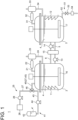
FIG. 1 is a schematic configuration diagram of a hydrogen production system according to the first embodiment of the present disclosure. -
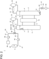
FIG. 2 is a schematic configuration diagram of a hydrogen production system according to the second embodiment of the present disclosure. - Hereinafter, a hydrogen production system according to embodiments of the present disclosure will be described with reference to the drawings. The embodiment to be described below indicates one aspect of the present disclosure, does not intend to limit the disclosure, and can optionally be modified within a range of a technical idea of the present disclosure.
- As shown in
FIG. 1 , ahydrogen production system 1 according to the first embodiment of the present disclosure includes afirst vessel 2 and asecond vessel 3. Each of thefirst vessel 2 and thesecond vessel 3 is configured to be able to containhydrogen compound slurry 4 in which a hydrogen compound member is suspended in a solvent containing water. Thefirst vessel 2 and thesecond vessel 3 are connected through two different passages, namely afirst passage 5 and asecond passage 6. Here, the solvent containing water is not limited to a solvent containing only water, and may be a solvent in which water is mixed with an organic solvent such as acetonitrile or acetone. - The hydrogen compound member has a configuration in which a powder material having a two-dimensional array of a hydrogen compound represented by chemical formula XmHn, where X is an element other than hydrogen (H), is supported on a particulate carrier, for example, beads. The stoichiometric ratio m:n is 1: 1 to 3:4 (for example, XH, XH2, XH3, XH4, X2H3, X3H4). The element X may be, but is not limited to, boron (B), for example.
- In the
hydrogen production system 1, the temperature in thesecond vessel 3, that is, the temperature of thehydrogen compound slurry 4 contained in thesecond vessel 3, is maintained higher than the temperature in thefirst vessel 2, that is, the temperature of thehydrogen compound slurry 4 contained in thefirst vessel 2. In order to maintain such a temperature relationship, a firsttemperature adjustment device 11 may be provided in thefirst vessel 2, and a secondtemperature adjustment device 12 may be provided in thesecond vessel 3. The configurations of the firsttemperature adjustment device 11 and the secondtemperature adjustment device 12 are not particularly limited, and may be, for example, coiled piping through which a heat medium for heat exchange with thehydrogen compound slurry 4 can flow. Specifically, the temperature range of the former is preferably 20°C to 150°C, and the temperature range of the latter is preferably 150°C to 250°C. In order to maintain water in the liquid state in such temperature ranges, the internal pressure of each of thefirst vessel 2 and thesecond vessel 3 is pressurized to at least atmospheric pressure or higher (e.g., 4 MPaG). - As described in detail in the description of the operation below, the hydrogen compound slurry 4 in the
first vessel 2 is transferred to thesecond vessel 3 through thefirst passage 5, and thehydrogen compound slurry 4 in thesecond vessel 3 is transferred to thefirst vessel 2 through thesecond passage 6. To achieve this operation, as an example, afirst pump 13 and asecond pump 14 may be provided on thefirst passage 5 and thesecond passage 6, respectively. Thefirst pump 13 and thesecond pump 14 can force thehydrogen compound slurry 4 to circulate between thefirst vessel 2 and thesecond vessel 3. - A
heat exchanger 15 may be provided to exchange heat between thehydrogen compound slurry 4 flowing through thefirst passage 5 and the hydrogen compound slurry 4 flowing through thesecond passage 6 while the hydrogen compound slurry 4 circulates between thefirst vessel 2 and thesecond vessel 3. - The
first vessel 2 and thesecond vessel 3 may be provided withstirring devices hydrogen compound slurry 4 contained therein. If there is no stagnation in the flow of the hydrogen compound slurry 4 when the hydrogen compound slurry 4 circulates between thefirst vessel 2 and thesecond vessel 3, the hydrogen compound member would not precipitate from thehydrogen compound slurry 4, but in practice, it is difficult to completely prevent the precipitation of the hydrogen compound member. In contrast, if the hydrogen compound slurry 4 in thefirst vessel 2 and thesecond vessel 3 are sufficiently stirred by thestirring devices first vessel 2 and thesecond vessel 3, respectively, the precipitation of the hydrogen compound member from thehydrogen compound slurry 4 can be suppressed. Stirring thehydrogen compound slurry 4 can also improve the temperature adjustment efficiency of thehydrogen compound slurry 4 by the firsttemperature adjustment device 11 and the secondtemperature adjustment device 12. - As described in detail in the description of the operation below, oxygen is produced when hydrogen is held by the hydrogen compound member in the
first vessel 2. To discharge the produced oxygen from thefirst vessel 2, thefirst vessel 2 may be connected to one end of anoutflow passage 21. Theoutflow passage 21 may be provided with aseparation device 22 for separating fluid flowing through theoutflow passage 21 into water and oxygen. Theseparation device 22 may be a cooler or a separation membrane device. If theseparation device 22 is a cooler, areflux tank 23 may be provided downstream of theseparation device 22 in theoutflow passage 21. To return the water separated by theseparation device 22 to thefirst vessel 2, awater return passage 24 may be provided with one end connected to theseparation device 22 or thereflux tank 23 and the other end connected to thefirst vessel 2. - As described in detail in the description of the operation below, hydrogen is released from the hydrogen compound member in the
second vessel 3. To discharge the released hydrogen from thesecond vessel 3, thesecond vessel 3 may be connected to one end of anoutflow passage 31. Theoutflow passage 31 may be provided with aseparation device 32 for separating fluid flowing through theoutflow passage 31 into water and hydrogen. Theseparation device 32 may be a cooler or a separation membrane device. If theseparation device 32 is a cooler, areflux tank 33 may be provided downstream of theseparation device 32 in theoutflow passage 31. To return the water separated by theseparation device 32 to thesecond vessel 3, awater return passage 34 may be provided with one end connected to theseparation device 32 or thereflux tank 33 and the other end connected to thesecond vessel 3. - As described in detail in the description of the operation below, while hydrogen is produced in the
hydrogen production system 1, water of thehydrogen compound slurry 4 is consumed. Awater supply device 25 may be provided to allow continuous production of hydrogen by replenishing the consumed water to thehydrogen production system 1. Water may be supplied into either thefirst vessel 2 or thesecond vessel 3, but it is preferable to supply water into thefirst vessel 2, where the internal temperature is lower, from the viewpoint of thermal efficiency. The specific configuration of thewater supply device 25 is not particularly limited, but for example, thewater supply device 25 may include awater supply passage 27 connected at one end to awater supply source 26 such as a tap or a water storage tank and connected at the other end to thefirst vessel 2, and apump 28 disposed on thewater supply passage 27. - The hydrogen compound member is not permanently usable and deteriorates in the course of hydrogen production. For this reason, a hydrogen
compound supply device 41 for supplying the hydrogen compound member into thefirst vessel 2, and adischarge device 51 for discharging thehydrogen compound slurry 4 in thesecond vessel 3 may be provided. Thereby, the deteriorated hydrogen compound member can be removed from thehydrogen production system 1, and a new hydrogen compound member can be supplied to thehydrogen production system 1, allowing continuous production of hydrogen. - The specific configuration of the hydrogen
compound supply device 41 is not particularly limited, but it may include, for example, aslurry tank 42, which is a storage for storing hydrogen compound slurry 4' containing a new hydrogen compound member, aslurry supply passage 43 connecting theslurry tank 42 and thefirst vessel 2, and asupply pump 44 disposed on theslurry supply passage 43. Theslurry supply passage 43 may be directly connected to thefirst vessel 2, or a merging passage 45, where theslurry supply passage 43 and thewater supply passage 27 join, may be connected to thefirst vessel 2. In the latter, athreeway valve 46 may be provided at the confluence between thewater supply passage 27 and theslurry supply passage 43 to switch between the supply of water from thewater supply source 26 and the supply of hydrogen compound slurry 4' from theslurry tank 42. - The hydrogen
compound supply device 41 may be configured to supply the new hydrogen compound member in the form of particle into thefirst vessel 2 or thewater supply passage 27, rather than in the form of slurry. However, if the particulate hydrogen compound member is directly supplied into thefirst vessel 2, the supplied hydrogen compound member may agglomerate. In contrast, if the new hydrogen compound member is supplied in the form of slurry, it is possible to reduce the possibility that the hydrogen compound member agglomerates. - The specific configuration of the
discharge device 51 is not particularly limited, but it may include, for example, adischarge passage 52 connected at one end to thesecond vessel 3, and avalve 53 disposed on thedischarge passage 52. Further, the discharge device may include a solid-liquid separator 54 for separating thehydrogen compound slurry 4 into solid and liquid phases. The specific configuration of the solid-liquid separator 54 is not particularly limited, but the solid-liquid separator 54 may be, for example, a filter. - Next, the operation of the
hydrogen production system 1 according to the first embodiment of the present disclosure will be described. Each of thefirst vessel 2 and thesecond vessel 3 contains thehydrogen compound slurry 4. For example, by the firsttemperature adjustment device 11 and the secondtemperature adjustment device 12, the temperature of thehydrogen compound slurry 4 in thefirst vessel 2 is maintained in the range of 100°C to 150°C, and the temperature of thehydrogen compound slurry 4 in thesecond vessel 3 is maintained in the range of 200°C to 250°C. In thefirst vessel 2, when the temperature of thehydrogen compound slurry 4 falls within the above range, water is decomposed into hydrogen and oxygen in the presence of the hydrogen compound member, and the hydrogen is absorbed into the hydrogen compound member. As a result, the hydrogen compound member stores hydrogen. The oxygen flows out of thefirst vessel 2 to theoutflow passage 21 and is separated into water and oxygen by theseparation device 22. The water is returned to thefirst vessel 2 through thewater return passage 24, and the oxygen is supplied to a storage facility or an oxygen consumption facility (not shown). In the first embodiment, the hydrogen compound member is in the form of slurry suspended in water, so the contact between water and the hydrogen compound member is good. In contrast, in the configuration where water or steam is supplied to the hydrogen compound member, the flow path of the water or steam may be fixed, and a portion of the hydrogen compound member may not be in contact with the water or steam. Thus, the use of thehydrogen compound slurry 4 allows hydrogen to be absorbed into the hydrogen compound member more efficiently than in the configuration where water or steam is supplied to the hydrogen compound member. - When the
hydrogen compound slurry 4 containing the hydrogen compound member that stores hydrogen flows into thesecond vessel 3 through thefirst passage 5 by thefirst pump 13, for example, the temperature rises to the range of 200°C to 250°C. When the hydrogen compound member that stores hydrogen falls within this temperature range, hydrogen is released from the hydrogen compound member. The hydrogen flows out of thesecond vessel 3 to theoutflow passage 31 and is separated into water and hydrogen by theseparation device 32. The water is returned to thesecond vessel 3 through thewater return passage 34, and the hydrogen is supplied to a storage facility or a hydrogen consumption facility (not shown). - When the
hydrogen compound slurry 4 containing the hydrogen compound member that has released hydrogen flows into thefirst vessel 2 through thesecond passage 6 by thesecond pump 14, for example, the temperature shifts to the range of 100°C to 150°C. When the hydrogen compound member that has released hydrogen falls within this temperature range, through the above-described operation, hydrogen is absorbed into the hydrogen compound member. As thehydrogen compound slurry 4 circulates between thefirst vessel 2 and thesecond vessel 3 having different temperatures, the hydrogen compound member stores hydrogen in thefirst vessel 2, and the hydrogen compound member releases hydrogen in thesecond vessel 3, whereby thehydrogen production system 1 produces hydrogen. - With the
hydrogen production system 1, hydrogen can be produced by moving thehydrogen compound slurry 4 containing the hydrogen compound member that stores hydrogen in thefirst vessel 2 into thesecond vessel 3, which has a higher temperature than thefirst vessel 2, releasing hydrogen from the hydrogen compound member in thesecond vessel 3, and moving thehydrogen compound slurry 4 containing the hydrogen compound member that has released hydrogen back into thefirst vessel 2, where the hydrogen compound member stores hydrogen again. With such operations, it is only necessary to raise or lower the temperature of thehydrogen compound slurry 4, and temperature changes in thefirst vessel 2 and thesecond vessel 3 containing thehydrogen compound slurry 4 can be suppressed as much as possible. Thus, the thermal efficiency can be improved, so that the manufacturing cost of hydrogen can be improved. - When the
hydrogen production system 1 is equipped with theheat exchanger 15, thehydrogen compound slurry 4 transferred from thefirst vessel 2 to thesecond vessel 3 is heated while thehydrogen compound slurry 4 transferred from thesecond vessel 3 to thefirst vessel 2 is cooled, so the load on the firsttemperature adjustment device 11 and the secondtemperature adjustment device 12 can be reduced. As a result, the thermal efficiency can be improved, and the manufacturing cost of hydrogen can be improved. - When the
hydrogen production system 1 is equipped with thewater supply device 25, water can be supplied from thewater supply device 25 into thefirst vessel 2 at a flow rate that compensates for water consumed in thefirst vessel 2 during the hydrogen production operation. This enables continuous production of hydrogen in thehydrogen production system 1. - As previously described, the hydrogen compound member deteriorates in the course of hydrogen production. When the
hydrogen production system 1 is equipped with the hydrogencompound supply device 41 and thedischarge device 51, the deteriorated hydrogen compound member can be discharged while replenishing a new hydrogen compound member. This enables continuous production of hydrogen. - When the
discharge device 51 includes the solid-liquid separator 54, the hydrogen compound slurry discharged from thesecond vessel 3 can be separated into solid and liquid phases, and the separated solid, i.e., the deteriorated hydrogen compound member, can be recovered. If the hydrogen compound member is recyclable, the recovered hydrogen compound member can be regenerated and then reused in thehydrogen production system 1. - Next, a hydrogen production system according to the second embodiment of the present disclosure will be described. The hydrogen production system according to the second embodiment is obtained by modifying the means for circulating the
hydrogen compound slurry 4 between thefirst vessel 2 and thesecond vessel 3 according to the first embodiment. In the second embodiment, the same constituent element as those in the first embodiment are associated with the same reference numerals and not described again in detail. - As shown in
FIG. 2 , in thehydrogen production system 1 according to the second embodiment of the present disclosure, thesecond passage 6 is disposed vertically above thefirst passage 5. The firsttemperature adjustment device 11 is disposed in thefirst vessel 2 so as to be located above the position where thefirst passage 5 is connected to thefirst vessel 2. The firsttemperature adjustment device 11 is preferably disposed at a position as high as possible in the vertical direction in thefirst vessel 2. Therefore, the firsttemperature adjustment device 11 is preferably disposed near the liquid level of thehydrogen compound slurry 4 in thefirst vessel 2. If thehydrogen compound slurry 4 is full in thefirst vessel 2, the firsttemperature adjustment device 11 is preferably disposed at the top of thefirst vessel 2. Since thehydrogen compound slurry 4 in thefirst vessel 2 is transferred to thesecond vessel 3 through thefirst passage 5, the liquid level of thehydrogen compound slurry 4 in thefirst vessel 2 should be at least above the position where thefirst passage 5 is connected to thefirst vessel 2. Therefore, the firsttemperature adjustment device 11 is disposed in thefirst vessel 2 at least above the position where thefirst passage 5 is connected to thefirst vessel 2. - The second
temperature adjustment device 12 is disposed in thesecond vessel 3 so as to be located below the position where thefirst passage 5 is connected to thesecond vessel 3. The secondtemperature adjustment device 12 is preferably disposed at a position as low as possible in the vertical direction in thesecond vessel 3. Therefore, the secondtemperature adjustment device 12 is preferably disposed at the bottom of thesecond vessel 3. Other configurations are the same as those in the first embodiment, except that the stirringdevices 16 and 17 (seeFIG. 1 ), the first pump 13 (seeFIG. 1 ) and the second pump 14 (seeFIG. 1 ) are not provided. - Next, the operation of the
hydrogen production system 1 according to the second embodiment of the present disclosure will be described. The second embodiment is different from the first embodiment only in the operation of circulating thehydrogen compound slurry 4 between thefirst vessel 2 and thesecond vessel 3, and the other operations are the same as those in the first embodiment. Therefore, only the circulation operation of thehydrogen compound slurry 4 will be described below. - When the
hydrogen compound slurry 4 is cooled by the firsttemperature adjustment device 11 in thefirst vessel 2, the cooledhydrogen compound slurry 4 moves downward in thefirst vessel 2 by convection. Thehydrogen compound slurry 4 that moves downward in thefirst vessel 2 then flows through thefirst passage 5 into thesecond vessel 3. When thehydrogen compound slurry 4 entering thesecond vessel 3 is heated by the secondtemperature adjustment device 12, the heatedhydrogen compound slurry 4 moves upward in thesecond vessel 3 by convection. Thehydrogen compound slurry 4 that moves upward in thesecond vessel 3 then flows through thesecond passage 6 into thefirst vessel 2. With such operations, thehydrogen compound slurry 4 can circulate between thefirst vessel 2 and thesecond vessel 3 by natural convection. Since the necessity of the pump for circulating thehydrogen compound slurry 4 is eliminated in the second embodiment, the manufacturing cost of hydrogen can be improved compared to the first embodiment. - In order to facilitate circulation of the
hydrogen compound slurry 4 between thefirst vessel 2 and thesecond vessel 3 by natural convection, each of thefirst vessel 2 and thesecond vessel 3 preferably has a shape elongated in the vertical direction. - The contents described in the above embodiments would be understood as follows, for instance.
- [1] A hydrogen production system according to one aspect includes: a hydrogen compound slurry (4) in which a hydrogen compound member is suspended in a solvent containing water; a first vessel (2); a second vessel (3) having an internal temperature higher than that of the first vessel (2); a first passage (5) connecting the first vessel (2) and the second vessel (3); and a second passage (6) connecting the first vessel (2) and the second vessel (3) and different from the first passage (5). The hydrogen production system is configured to allow the hydrogen compound slurry (4) contained in the first vessel (2) to move into the second vessel (3) through the first passage (5), and the hydrogen compound slurry (4) contained in the second vessel (3) to move into the first vessel (2) through the second passage (6).
- With the hydrogen production system of the present disclosure, hydrogen can be produced by moving the hydrogen compound slurry containing the hydrogen compound member that stores hydrogen in the first vessel into the second vessel, which has a higher temperature than the first vessel, releasing hydrogen from the hydrogen compound member in the second vessel, and moving the hydrogen compound slurry containing the hydrogen compound member that has released hydrogen back into the first vessel, where the hydrogen compound member stores hydrogen again. With such operations, it is only necessary to raise or lower the temperature of the hydrogen compound slurry, and temperature changes in the first vessel and the second vessel containing the hydrogen compound slurry can be suppressed as much as possible. Thus, the thermal efficiency can be improved, so that the manufacturing cost of hydrogen can be improved.
- [2] A hydrogen production system according to another aspect is the hydrogen production system of [1], including: a first temperature adjustment device (11) for adjusting a temperature of the hydrogen compound slurry (4) in the first vessel (2); and a second temperature adjustment device (12) for adjusting a temperature of the hydrogen compound slurry (4) in the second vessel (3).
- With this configuration, it is possible to maintain the temperature of the hydrogen compound slurry in the first vessel in a temperature range that allows hydrogen to be stored in the hydrogen compound, and the temperature of the hydrogen compound slurry in the second vessel in a temperature range that allows hydrogen to be released from the hydrogen compound.
- [3] A hydrogen production system according to still another aspect is the hydrogen production system of [1] or [2], including: a first pump (13), disposed on the first passage (5), for transferring the hydrogen compound slurry (4) in the first vessel (2) to the second vessel (3); and a second pump (14), disposed on the second passage (6), for transferring the hydrogen compound slurry (4) in the second vessel (3) to the first vessel (2).
- This configuration can force the hydrogen compound slurry to circulate between the first vessel and the second vessel.
- [4] A hydrogen production system according to still another aspect is the hydrogen production system of [2], in which the second passage (6) is disposed vertically above the first passage (5), the first temperature adjustment device (11) is disposed in the first vessel (2) so as to be located above a position where the first passage (5) is connected to the first vessel (2), and the second temperature adjustment device (12) is disposed in the second vessel (3) so as to be located below a position where the first passage (5) is connected to the second vessel (3).
- With this configuration, due to convection caused by cooling the hydrogen compound slurry with the first temperature adjustment device in the first vessel, the hydrogen compound slurry moves downward in the first vessel, and then flows through the first passage into the second vessel. The hydrogen compound slurry entering the second vessel is heated by the second temperature adjustment device, and due to convection caused by this heating, the slurry moves upward in the second vessel, and then flows through the second passage into the first vessel. With such operations, the hydrogen compound slurry can circulate between the first vessel and the second vessel by natural convection. In this configuration, since the necessity of the pump for circulating the hydrogen compound slurry between the first vessel and the second vessel is eliminated, the manufacturing cost of hydrogen can be improved compared to the configuration [3].
- [5] A hydrogen production system according to still another aspect is the hydrogen production system of any one of [1] to [4], including a heat exchanger (15) for exchanging heat between the hydrogen compound slurry (4) flowing through the first passage (5) and the hydrogen compound slurry (4) flowing through the second passage (6).
- With this configuration, the hydrogen compound slurry transferred from the first vessel to the second vessel is heated while the hydrogen compound slurry transferred from the second vessel to the first vessel is cooled, so the load on the first temperature adjustment device and the second temperature adjustment device can be reduced. As a result, the thermal efficiency can be improved, and the manufacturing cost of hydrogen can be improved.
- [6] A hydrogen production system according to still another aspect is the hydrogen production system of any one of [1] to [5], including a water supply device (25) for supplying water to the first vessel (2).
- With this configuration, water consumed by storing hydrogen in the first vessel can be replenished, allowing continuous production of hydrogen.
- [7] A hydrogen production system according to still another aspect is the hydrogen production system of any one of [1] to [6], including: a discharge device (51) for discharging the hydrogen compound slurry (4) in the second vessel (3); and a hydrogen compound supply device (41) for supplying the hydrogen compound member to the first vessel (2).
- With this configuration, the deteriorated hydrogen compound member can be discharged, and on the other hand, a new hydrogen compound member can be supplied, allowing continuous production of hydrogen.
- [8] A hydrogen production system according to still another aspect is the hydrogen production system of [7], in which the discharge device (51) includes a solid-liquid separator (54) for separating the hydrogen compound slurry (4) into solid and liquid phases.
- With this configuration, if the hydrogen compound member is recyclable, the hydrogen compound member can be recovered by separating it from the discharged hydrogen compound slurry, and the recovered hydrogen compound member can be reused after regeneration.
- [9] A hydrogen production system according to still another aspect is the hydrogen production system of [8], in which the hydrogen compound supply device (41) includes: a storage (slurry tank 42) for storing the hydrogen compound slurry (4); a slurry supply passage (43) connecting the storage (42) and the first vessel (2); and a supply pump (44), disposed on the slurry supply passage (43), for supplying the hydrogen compound slurry (4) in the storage (42) to the first vessel (2).
- If the particulate hydrogen compound member is directly supplied into the first vessel, the supplied hydrogen compound member may agglomerate. In contrast, if the new hydrogen compound member is supplied in the form of slurry, it is possible to reduce the possibility that the hydrogen compound member agglomerates.
Claims (9)
- A hydrogen production system, comprising:a hydrogen compound slurry in which a hydrogen compound member is suspended in a solvent containing water;a first vessel;a second vessel having an internal temperature higher than that of the first vessel;a first passage connecting the first vessel and the second vessel; anda second passage connecting the first vessel and the second vessel and different from the first passage,wherein the hydrogen production system is configured to allow the hydrogen compound slurry contained in the first vessel to move into the second vessel through the first passage, and the hydrogen compound slurry contained in the second vessel to move into the first vessel through the second passage.
- The hydrogen production system according to claim 1, comprising:a first temperature adjustment device for adjusting a temperature of the hydrogen compound slurry in the first vessel; anda second temperature adjustment device for adjusting a temperature of the hydrogen compound slurry in the second vessel.
- The hydrogen production system according to claim 1 or 2, comprising:a first pump, disposed on the first passage, for transferring the hydrogen compound slurry in the first vessel to the second vessel; anda second pump, disposed on the second passage, for transferring the hydrogen compound slurry in the second vessel to the first vessel.
- The hydrogen production system according to claim 2,wherein the second passage is disposed vertically above the first passage,wherein the first temperature adjustment device is disposed in the first vessel so as to be located above a position where the first passage is connected to the first vessel, andwherein the second temperature adjustment device is disposed in the second vessel so as to be located below a position where the first passage is connected to the second vessel.
- The hydrogen production system according to any one of claims 1 to 4, comprising a heat exchanger for exchanging heat between the hydrogen compound slurry flowing through the first passage and the hydrogen compound slurry flowing through the second passage.
- The hydrogen production system according to any one of claims 1 to 5, comprising a water supply device for supplying water to the first vessel.
- The hydrogen production system according to any one of claims 1 to 6, comprising:a discharge device for discharging the hydrogen compound slurry in the second vessel; anda hydrogen compound supply device for supplying the hydrogen compound member to the first vessel.
- The hydrogen production system according to claim 7,
wherein the discharge device includes a solid-liquid separator for separating the hydrogen compound slurry into solid and liquid phases. - The hydrogen production system according to claim 8,
wherein the hydrogen compound supply device includes:a storage for storing the hydrogen compound slurry;a slurry supply passage connecting the storage and the first vessel; anda supply pump, disposed on the slurry supply passage, for supplying the hydrogen compound slurry in the storage to the first vessel.
Applications Claiming Priority (1)
| Application Number | Priority Date | Filing Date | Title |
|---|---|---|---|
| JP2022051877A JP7811873B2 (en) | 2022-03-28 | 2022-03-28 | Hydrogen Production System |
Publications (2)
| Publication Number | Publication Date |
|---|---|
| EP4253312A1 true EP4253312A1 (en) | 2023-10-04 |
| EP4253312B1 EP4253312B1 (en) | 2025-07-23 |
Family
ID=85239048
Family Applications (1)
| Application Number | Title | Priority Date | Filing Date |
|---|---|---|---|
| EP23156505.2A Active EP4253312B1 (en) | 2022-03-28 | 2023-02-14 | Hydrogen production system |
Country Status (5)
| Country | Link |
|---|---|
| US (1) | US12595170B2 (en) |
| EP (1) | EP4253312B1 (en) |
| JP (1) | JP7811873B2 (en) |
| CN (1) | CN116812864A (en) |
| AU (1) | AU2023200809B2 (en) |
Families Citing this family (1)
| Publication number | Priority date | Publication date | Assignee | Title |
|---|---|---|---|---|
| CN121016617B (en) * | 2025-10-28 | 2026-04-17 | 西安一九零八新能源科技有限公司 | Solid hydrogen storage material controllable hydrolysis hydrogen production system and method with self-circulation function |
Citations (6)
| Publication number | Priority date | Publication date | Assignee | Title |
|---|---|---|---|---|
| US20020081235A1 (en) * | 2000-07-13 | 2002-06-27 | Baldwin Edward W. | Method and apparatus for controlled generation of hydrogen by dissociation of water |
| US20060042162A1 (en) * | 2004-09-01 | 2006-03-02 | Jonathan Goldstein | System for hydrogen storage and generation |
| US20160214858A1 (en) * | 2013-10-21 | 2016-07-28 | Air Products And Chemicals, Inc. | Multi-zone dehydrogenation reactor and ballasting system for storage and delivery of hydrogen |
| JP2019218251A (en) | 2018-06-22 | 2019-12-26 | 国立大学法人東京工業大学 | Hydrogen generation method, hydrogen generation system, and fuel cell system |
| WO2020064222A1 (en) * | 2018-09-27 | 2020-04-02 | Hydrogenious Lohc Technologies Gmbh | Apparatus and method for releasing chemically bound hydrogen in the form of hydrogen gas under pressure and device and hydrogen filling station comprising such an apparatus |
| JP2022051877A (en) | 2017-08-04 | 2022-04-01 | 株式会社ダイセル | Anti-glare film |
Family Cites Families (9)
| Publication number | Priority date | Publication date | Assignee | Title |
|---|---|---|---|---|
| NL8201885A (en) * | 1982-05-07 | 1983-12-01 | Stamicarbon | METHOD AND APPARATUS FOR SEPARATING A GAS FROM THE MIXTURE OF GASES, FOR EXAMPLE HYDROGEN. |
| US4769225A (en) * | 1983-12-08 | 1988-09-06 | The United States Of America As Represented By The United States Department Of Energy | System for exchange of hydrogen between liquid and solid phases |
| JP3989229B2 (en) | 2001-11-16 | 2007-10-10 | 大阪瓦斯株式会社 | Hydrogen storage material transfer device |
| CN101296859A (en) * | 2005-10-31 | 2008-10-29 | 日立麦克赛尔株式会社 | Device for producing hydrogen and fuel cell system using the device |
| JP5839378B2 (en) | 2012-06-19 | 2016-01-06 | バイオコーク技研株式会社 | Hydrogen generator |
| JP2014001117A (en) * | 2012-06-20 | 2014-01-09 | Sharp Corp | Hydrogen production apparatus and power generator |
| US9878907B2 (en) | 2015-10-12 | 2018-01-30 | Cavendish Energy | System and method to produce hydrogen |
| JP2019151514A (en) * | 2018-03-02 | 2019-09-12 | パナソニックIpマネジメント株式会社 | Hydrogen generation device, and operation method therefor |
| JP7354050B2 (en) | 2020-04-13 | 2023-10-02 | 三菱重工業株式会社 | Hydrogen release/storage system, hydrogen release/storage method, hydrogen release/storage device, ammonia production device, gas turbine, fuel cell, and steelworks |
-
2022
- 2022-03-28 JP JP2022051877A patent/JP7811873B2/en active Active
- 2022-12-29 CN CN202211742033.4A patent/CN116812864A/en active Pending
-
2023
- 2023-02-06 US US18/164,897 patent/US12595170B2/en active Active
- 2023-02-14 AU AU2023200809A patent/AU2023200809B2/en active Active
- 2023-02-14 EP EP23156505.2A patent/EP4253312B1/en active Active
Patent Citations (6)
| Publication number | Priority date | Publication date | Assignee | Title |
|---|---|---|---|---|
| US20020081235A1 (en) * | 2000-07-13 | 2002-06-27 | Baldwin Edward W. | Method and apparatus for controlled generation of hydrogen by dissociation of water |
| US20060042162A1 (en) * | 2004-09-01 | 2006-03-02 | Jonathan Goldstein | System for hydrogen storage and generation |
| US20160214858A1 (en) * | 2013-10-21 | 2016-07-28 | Air Products And Chemicals, Inc. | Multi-zone dehydrogenation reactor and ballasting system for storage and delivery of hydrogen |
| JP2022051877A (en) | 2017-08-04 | 2022-04-01 | 株式会社ダイセル | Anti-glare film |
| JP2019218251A (en) | 2018-06-22 | 2019-12-26 | 国立大学法人東京工業大学 | Hydrogen generation method, hydrogen generation system, and fuel cell system |
| WO2020064222A1 (en) * | 2018-09-27 | 2020-04-02 | Hydrogenious Lohc Technologies Gmbh | Apparatus and method for releasing chemically bound hydrogen in the form of hydrogen gas under pressure and device and hydrogen filling station comprising such an apparatus |
Also Published As
| Publication number | Publication date |
|---|---|
| EP4253312B1 (en) | 2025-07-23 |
| JP7811873B2 (en) | 2026-02-06 |
| JP2023144750A (en) | 2023-10-11 |
| CN116812864A (en) | 2023-09-29 |
| AU2023200809B2 (en) | 2024-02-15 |
| US20230303390A1 (en) | 2023-09-28 |
| AU2023200809A1 (en) | 2023-10-12 |
| US12595170B2 (en) | 2026-04-07 |
Similar Documents
| Publication | Publication Date | Title |
|---|---|---|
| US9863725B1 (en) | Systems and methods for thermal management through use of ammonium carbamate | |
| JP2014531721A (en) | Flow battery with two-phase storage | |
| EP4253312B1 (en) | Hydrogen production system | |
| US11255575B2 (en) | Process and system for hot and/or cold energy transfer, transport and/or storage | |
| CN106662411B (en) | equipment for storing liquids | |
| CN116557759A (en) | Purified hydrogen storage device and purified hydrogen storage method | |
| JP2002343405A (en) | Fuel cell vehicle, hydrogen supply device for fuel cell vehicle, hydrogen storage container and stacker thereof, hydrogen storage container transport device, and exchange device | |
| EP0094136A1 (en) | Process for the separation of hydrogen from a mixture of gases | |
| KR102315357B1 (en) | Electrical energy storage device and method of operation of the device | |
| CN120485808A (en) | Efficient hydrogen production system and method for immersed alkaline electrolytic tank | |
| EP4361093A1 (en) | Hydrogen production system | |
| CN118463686A (en) | Efficient phase-change heat accumulating type ship heat recovery and anti-freezing device | |
| EP0353992A2 (en) | Methods of heat transfer and apparatus therefor | |
| CN106163653A (en) | Reactor system and its use | |
| AU2022433544A1 (en) | Carbon dioxide recovery system | |
| CN107144028A (en) | A kind of Solar use method for separating out solid heat storage | |
| US6864293B2 (en) | Production of liquid and, optionally, gaseous products from gaseous reactants | |
| JPS58104494A (en) | Direct heat exchange type latent heat accumulator | |
| JPH0227387B2 (en) | ||
| CN216366677U (en) | Rectifying device | |
| CN222690703U (en) | Hydrogen supply module, hydrogen storage and supply system and automobile | |
| EP4592247A1 (en) | Ammonia synthesis system and its operation method | |
| KR20250121207A (en) | Molten salt reactor and vehicle including the same | |
| KR20250047176A (en) | Energy storage apparatus having temperature distribution | |
| KR20180010603A (en) | Hydrogen supplement apparatus for submarine |
Legal Events
| Date | Code | Title | Description |
|---|---|---|---|
| PUAI | Public reference made under article 153(3) epc to a published international application that has entered the european phase |
Free format text: ORIGINAL CODE: 0009012 |
|
| STAA | Information on the status of an ep patent application or granted ep patent |
Free format text: STATUS: THE APPLICATION HAS BEEN PUBLISHED |
|
| AK | Designated contracting states |
Kind code of ref document: A1 Designated state(s): AL AT BE BG CH CY CZ DE DK EE ES FI FR GB GR HR HU IE IS IT LI LT LU LV MC ME MK MT NL NO PL PT RO RS SE SI SK SM TR |
|
| STAA | Information on the status of an ep patent application or granted ep patent |
Free format text: STATUS: REQUEST FOR EXAMINATION WAS MADE |
|
| 17P | Request for examination filed |
Effective date: 20231017 |
|
| RBV | Designated contracting states (corrected) |
Designated state(s): AL AT BE BG CH CY CZ DE DK EE ES FI FR GB GR HR HU IE IS IT LI LT LU LV MC ME MK MT NL NO PL PT RO RS SE SI SK SM TR |
|
| STAA | Information on the status of an ep patent application or granted ep patent |
Free format text: STATUS: EXAMINATION IS IN PROGRESS |
|
| 17Q | First examination report despatched |
Effective date: 20241218 |
|
| GRAP | Despatch of communication of intention to grant a patent |
Free format text: ORIGINAL CODE: EPIDOSNIGR1 |
|
| STAA | Information on the status of an ep patent application or granted ep patent |
Free format text: STATUS: GRANT OF PATENT IS INTENDED |
|
| INTG | Intention to grant announced |
Effective date: 20250224 |
|
| GRAS | Grant fee paid |
Free format text: ORIGINAL CODE: EPIDOSNIGR3 |
|
| GRAA | (expected) grant |
Free format text: ORIGINAL CODE: 0009210 |
|
| STAA | Information on the status of an ep patent application or granted ep patent |
Free format text: STATUS: THE PATENT HAS BEEN GRANTED |
|
| AK | Designated contracting states |
Kind code of ref document: B1 Designated state(s): AL AT BE BG CH CY CZ DE DK EE ES FI FR GB GR HR HU IE IS IT LI LT LU LV MC ME MK MT NL NO PL PT RO RS SE SI SK SM TR |
|
| REG | Reference to a national code |
Ref country code: GB Ref legal event code: FG4D |
|
| REG | Reference to a national code |
Ref country code: CH Ref legal event code: EP |
|
| REG | Reference to a national code |
Ref country code: DE Ref legal event code: R096 Ref document number: 602023004924 Country of ref document: DE |
|
| REG | Reference to a national code |
Ref country code: IE Ref legal event code: FG4D |
|
| REG | Reference to a national code |
Ref country code: NL Ref legal event code: MP Effective date: 20250723 |
|
| PG25 | Lapsed in a contracting state [announced via postgrant information from national office to epo] |
Ref country code: PT Free format text: LAPSE BECAUSE OF FAILURE TO SUBMIT A TRANSLATION OF THE DESCRIPTION OR TO PAY THE FEE WITHIN THE PRESCRIBED TIME-LIMIT Effective date: 20251124 |
|
| PG25 | Lapsed in a contracting state [announced via postgrant information from national office to epo] |
Ref country code: NL Free format text: LAPSE BECAUSE OF FAILURE TO SUBMIT A TRANSLATION OF THE DESCRIPTION OR TO PAY THE FEE WITHIN THE PRESCRIBED TIME-LIMIT Effective date: 20250723 |
|
| REG | Reference to a national code |
Ref country code: AT Ref legal event code: MK05 Ref document number: 1816287 Country of ref document: AT Kind code of ref document: T Effective date: 20250723 |
|
| PG25 | Lapsed in a contracting state [announced via postgrant information from national office to epo] |
Ref country code: IS Free format text: LAPSE BECAUSE OF FAILURE TO SUBMIT A TRANSLATION OF THE DESCRIPTION OR TO PAY THE FEE WITHIN THE PRESCRIBED TIME-LIMIT Effective date: 20251123 |
|
| PG25 | Lapsed in a contracting state [announced via postgrant information from national office to epo] |
Ref country code: NO Free format text: LAPSE BECAUSE OF FAILURE TO SUBMIT A TRANSLATION OF THE DESCRIPTION OR TO PAY THE FEE WITHIN THE PRESCRIBED TIME-LIMIT Effective date: 20251023 |
|
| REG | Reference to a national code |
Ref country code: LT Ref legal event code: MG9D |
|
| PG25 | Lapsed in a contracting state [announced via postgrant information from national office to epo] |
Ref country code: AT Free format text: LAPSE BECAUSE OF FAILURE TO SUBMIT A TRANSLATION OF THE DESCRIPTION OR TO PAY THE FEE WITHIN THE PRESCRIBED TIME-LIMIT Effective date: 20250723 |
|
| PG25 | Lapsed in a contracting state [announced via postgrant information from national office to epo] |
Ref country code: FI Free format text: LAPSE BECAUSE OF FAILURE TO SUBMIT A TRANSLATION OF THE DESCRIPTION OR TO PAY THE FEE WITHIN THE PRESCRIBED TIME-LIMIT Effective date: 20250723 |
|
| PG25 | Lapsed in a contracting state [announced via postgrant information from national office to epo] |
Ref country code: HR Free format text: LAPSE BECAUSE OF FAILURE TO SUBMIT A TRANSLATION OF THE DESCRIPTION OR TO PAY THE FEE WITHIN THE PRESCRIBED TIME-LIMIT Effective date: 20250723 |
|
| PG25 | Lapsed in a contracting state [announced via postgrant information from national office to epo] |
Ref country code: GR Free format text: LAPSE BECAUSE OF FAILURE TO SUBMIT A TRANSLATION OF THE DESCRIPTION OR TO PAY THE FEE WITHIN THE PRESCRIBED TIME-LIMIT Effective date: 20251024 |
|
| PG25 | Lapsed in a contracting state [announced via postgrant information from national office to epo] |
Ref country code: SE Free format text: LAPSE BECAUSE OF FAILURE TO SUBMIT A TRANSLATION OF THE DESCRIPTION OR TO PAY THE FEE WITHIN THE PRESCRIBED TIME-LIMIT Effective date: 20250723 |
|
| PG25 | Lapsed in a contracting state [announced via postgrant information from national office to epo] |
Ref country code: LV Free format text: LAPSE BECAUSE OF FAILURE TO SUBMIT A TRANSLATION OF THE DESCRIPTION OR TO PAY THE FEE WITHIN THE PRESCRIBED TIME-LIMIT Effective date: 20250723 |
|
| PG25 | Lapsed in a contracting state [announced via postgrant information from national office to epo] |
Ref country code: PL Free format text: LAPSE BECAUSE OF FAILURE TO SUBMIT A TRANSLATION OF THE DESCRIPTION OR TO PAY THE FEE WITHIN THE PRESCRIBED TIME-LIMIT Effective date: 20250723 Ref country code: BG Free format text: LAPSE BECAUSE OF FAILURE TO SUBMIT A TRANSLATION OF THE DESCRIPTION OR TO PAY THE FEE WITHIN THE PRESCRIBED TIME-LIMIT Effective date: 20250723 |
|
| PG25 | Lapsed in a contracting state [announced via postgrant information from national office to epo] |
Ref country code: RS Free format text: LAPSE BECAUSE OF FAILURE TO SUBMIT A TRANSLATION OF THE DESCRIPTION OR TO PAY THE FEE WITHIN THE PRESCRIBED TIME-LIMIT Effective date: 20251023 |
|
| PG25 | Lapsed in a contracting state [announced via postgrant information from national office to epo] |
Ref country code: ES Free format text: LAPSE BECAUSE OF FAILURE TO SUBMIT A TRANSLATION OF THE DESCRIPTION OR TO PAY THE FEE WITHIN THE PRESCRIBED TIME-LIMIT Effective date: 20250723 |
|
| PG25 | Lapsed in a contracting state [announced via postgrant information from national office to epo] |
Ref country code: SM Free format text: LAPSE BECAUSE OF FAILURE TO SUBMIT A TRANSLATION OF THE DESCRIPTION OR TO PAY THE FEE WITHIN THE PRESCRIBED TIME-LIMIT Effective date: 20250723 |
|
| PG25 | Lapsed in a contracting state [announced via postgrant information from national office to epo] |
Ref country code: DK Free format text: LAPSE BECAUSE OF FAILURE TO SUBMIT A TRANSLATION OF THE DESCRIPTION OR TO PAY THE FEE WITHIN THE PRESCRIBED TIME-LIMIT Effective date: 20250723 |
|
| PGFP | Annual fee paid to national office [announced via postgrant information from national office to epo] |
Ref country code: DE Payment date: 20251230 Year of fee payment: 4 |
|
| PG25 | Lapsed in a contracting state [announced via postgrant information from national office to epo] |
Ref country code: IT Free format text: LAPSE BECAUSE OF FAILURE TO SUBMIT A TRANSLATION OF THE DESCRIPTION OR TO PAY THE FEE WITHIN THE PRESCRIBED TIME-LIMIT Effective date: 20250723 |
|
| PG25 | Lapsed in a contracting state [announced via postgrant information from national office to epo] |
Ref country code: CZ Free format text: LAPSE BECAUSE OF FAILURE TO SUBMIT A TRANSLATION OF THE DESCRIPTION OR TO PAY THE FEE WITHIN THE PRESCRIBED TIME-LIMIT Effective date: 20250723 |
|
| PG25 | Lapsed in a contracting state [announced via postgrant information from national office to epo] |
Ref country code: EE Free format text: LAPSE BECAUSE OF FAILURE TO SUBMIT A TRANSLATION OF THE DESCRIPTION OR TO PAY THE FEE WITHIN THE PRESCRIBED TIME-LIMIT Effective date: 20250723 Ref country code: SK Free format text: LAPSE BECAUSE OF FAILURE TO SUBMIT A TRANSLATION OF THE DESCRIPTION OR TO PAY THE FEE WITHIN THE PRESCRIBED TIME-LIMIT Effective date: 20250723 |